

Page 1

IMAGETEAM™ 4410/4710
2D Series
Hand Held Imager
™
User’s Guide
Page 2

Statement of Agency Compliance for the IT4410/4710
This device com plies with part 1 5 of the FCC Rules . O perati on is sub ject to the
following two conditions : (1) this device may not cause har mful interference, and
(2) this device must accep t any interference received , including interference tha t
may cause undesired operation.
FCC Class B Compliance Statement
This equipment has been tested and found to comply with the limits for a Class
B digital device pursu ant to part 15 of the FCC Ru les. These limits ar e designed
to provide reasonable protection against harmful interference in a residential
installation. This equipment generates, uses, and can radiate radio frequency
energy and, if not installed and used in accordance with the instructions, may
cause harmful interference to radio communications. However, there is no
guarantee that interference will not occur in a particular installation. If this
equipment does cause harmful interference to radio or television reception,
which can be determined by turning the equipment off and on, the user is
encouraged to try to correct the interference by one or more of the following
measures:
• Reorient or relocate the receiving antenna.
• Increase the separation between the equipment and receiver.
• Connect the equipment into an outlet on a circuit different from that to
which the receiver is connected.
• Consult the dealer or a n experienced radio or t elevision technician f or
help.
Caution: Any changes or modifications made to this device that are not
expressly approved by Hand Held Products may void the user’s authority to
operate the equipment.
Note: To maintain compliance with FCC Rules and Regulations, cables
connected to this device must be shielded cables, in which the cable shield
wire(s) have been grounded (tied) to the connector shell.
Canadian Notice
This equipment does not ex ceed the Clas s B limits fo r radio noise em issions as
described in the Radio Inte rference Re gulations of the Canadian D epartme nt of
Communications.
Le present appa reil num erique n ’emet p as de bruits radio elect riques depa ssant
les limites applica bles aux appa reils numeri ques de la clas se B prescrites dans
le Reglement sur le brouillage radioelectrique edicte par le ministere des
Communications du Canada.
EN 60825-1 LED Safety Statement
This product is class ified per EN 60825 -1 : 1994, Issue 2, June 1997 as a Class
1 LED Product.
Page 3

The CE mark on the product indicates that the system has been
tested to and conforms wit h the provis ions note d within the 8 9/336/
EEC Electromagnetic Compatibility Directive and the 73/23/EEC
Low Voltage Directive.
For further information please contact:
Hand Held Products (UK) Ltd.
1st Floor
Dallam Court Dallam Lane
Warrington, Cheshir e WA2 7LT
England
Hand Held Products shal l not be liable for use of our product with equipment
(i.e., power supplies, persona l compute rs, etc.) tha t is not CE marked and does
not comply with the Low Voltage Directive.
Patents
The IMAGETEAM 4410/4710 products are covered by one or more of the
following U.S. Patents: 3,991,299; 4,570, 057; 5,021,642; 5,038,024;
5,081,343; 5,095,197 ; 5,144,1 19; 5,14 4,121; 5, 182 ,441; 5,1 87,355 ; 5,187,3 56;
5,218,191; 5,233,172 ; 5,258,6 06; 5,28 6,960; 5, 288 ,985; 5,4 20,409 ; 5,463,2 14;
5,541,419; 5,569,902 ; 5,591,9 56; 5,72 3,853; 5, 723 ,868; 5,7 73,806 ; 5,773,8 10;
5,780,834; 5,784,102 ; 5,786,5 86; 5,82 5,006; 5, 837 ,985; 5,8 38,495 ; 5,900,6 13;
5,914,476; D400,199; 5,92 9,4 18; 5,932,862; 5,942,741; 5,949 ,05 2; 5,9 65, 863;
5,992,744; 6,045,047; 6,060,722.
Other U.S. and foreign patents pending.
Disclaimer
Welch Allyn
Data Collection, Inc. (d/b/a Hand Held Products) reserves the right
to make changes in specifications and other information contained in this
document without prior no tic e, an d the reader should in all cases consult Hand
Held Products to determine whether any such changes have been made. The
information in this publication does not represent a commitment on the part of
Hand Held Products.
Hand Held P roducts shall not be liable for technical or editorial errors or
omissions contained herein; nor for incidental or consequential damages
resulting from the furnishing, performance, or use of this material.
This document cont ains proprietary information wh ich is protected b y copyright.
All rights are reserved. No part of this document may be photocopied,
reproduced, or translated into another language without the prior writte n consent
of Hand Held Products.
2000-2201 Welch Allyn Data Collection, Inc. All rights reserved.
Web Address: www.handheld.com
Page 4

Page 5

Table of Contents
Chapter 1 - Introduction and Installation
About the Hand-Held and Fixed Mount 2D Imager............. 1-1
Unpacking the Imager........................................................... 1-2
IT4410 Imager Identification................................................ 1-4
IT4710 Imager Identification................................................ 1-5
Connecting the Scanner in Keyboard Wedge Mode............. 1-6
Connecting the Scanner to a Serial Port ............................... 1-7
Reading Techniques.............................................................. 1-8
Chapter 2 - Programming
Introduction........................................................................... 2-1
Reset Factory Settings .......................................................... 2-2
Status Check ......................................................................... 2-2
All Symbologies ................................................................... 2-2
Revision Selections............................................................... 2-3
Terminal Interface ................................................................ 2-4
Supported Terminals Chart................................................... 2-5
Keyboard Country ................................................................ 2-6
Keyboard Style ..................................................................... 2-7
Keyboard Modifiers.............................................................. 2-8
Keyboard Function Relationships......................................... 2-9
Communication Settings..................................................... 2-10
Parity ............................................................................ 2-10
Baud Rate..................................................................... 2-11
Word Length Data Bits ................................................ 2-12
Word Length Stop Bits................................................. 2-12
Hardware Flow Control................................................ 2-13
Software Flow Control................................................. 2-13
Serial Triggering .......................................................... 2-14
Trigger Timeout.................................................................. 2-15
Power Saving Mode............................................................ 2-16
Power Hold Mode............................................................... 2-17
LED Power Level ............................................................... 2-17
LED Flashing...................................................................... 2-18
i
Page 6

Aimer Delay........................................................................2-18
Aimer Interval .....................................................................2-19
Centering............................................................................. 2-20
Scan Stand...........................................................................2-24
Scan Stand Symbol.......................................................2-24
Presentation Mode...............................................................2-25
Presentation Re-trigger Delay ......................................2-25
Presentation Lights .......................................................2-25
Presentation Default .....................................................2-25
Beeper Volume....................................................................2-26
Power Up Beeper ................................................................2-26
Output Sequence Beeper.....................................................2-26
Beep On Decode .................................................................2-27
Beeper Default..............................................................2-27
Intercharacter, Interfunction,
and Intermessage Delays..................................................2-28
Intercharacter Delay .................................................... 2-28
User Specified Intercharacter Delay ............................ 2-28
Interfunction Delay ......................................................2-29
Intermessage Delay ......................................................2-30
Prefix/Suffix Overview.......................................................2-31
Adding a Prefix or Suffix .............................................2-32
Add a Carriage Return Suffix to All Symbologies ...... 2-33
Add a Code I.D. Prefix to All Symbologies ................ 2-33
Add an AIM I.D. Prefix to All Symbologies ............... 2-33
Prefix Entries................................................................2-34
Suffix Entries................................................................2-34
Symbology Chart ................................................................2-35
Decimal to Hex to ASCII Conversion Chart.......................2-36
Data Format Editor Overview.............................................2-37
Format Editor Commands ............................................2-38
Data Format Editor .......................................................2-40
Data Formatter..............................................................2-41
Require Data Format ....................................................2-41
Show Data Formats ......................................................2-41
Alternate Data Formats................................................. 2-42
ii
Page 7

Output Sequence Overview.................................................2-43
Require Output Sequence .............................................2-45
Output Sequence Editor................................................2-46
Multiple Symbols ................................................................2-47
No Read...............................................................................2-47
Print Weight ........................................................................2-48
Function Code Transmit......................................................2-48
Video Reverse .....................................................................2-49
Chapter 3 - Symbologies
Introduction ...........................................................................3-1
Codabar .................................................................................3-2
Start/Stop Characters ......................................................3-2
Message Length ..............................................................3-2
Check Character..............................................................3-3
Code 39..................................................................................3-4
Start/Stop Characters ......................................................3-4
Message Length ..............................................................3-4
Full ASCII.......................................................................3-5
Check Character..............................................................3-6
Code 11..................................................................................3-7
Message Length ..............................................................3-7
Check Digits Required....................................................3-8
Interleaved 2 of 5...................................................................3-9
Message Length ..............................................................3-9
Check Digit...................................................................3-10
IATA 2 of 5 .........................................................................3-11
Message Length ............................................................3-11
MSI......................................................................................3-12
Message Length ............................................................3-12
Check Digit...................................................................3-13
Code 93................................................................................3-14
Message Length ............................................................3-14
Code 128..............................................................................3-15
Message Length ............................................................3-15
ISBT ....................................................................................3-16
iii
Page 8

EAN/JAN 8 ......................................................................... 3-17
Check Digit...................................................................3-17
EAN/JAN 8 Addenda ...................................................3-18
EAN/JAN 8 Addenda Required ...................................3-18
EAN/JAN 8 Addenda Separator...................................3-18
EAN/JAN 13 ....................................................................... 3-19
Check Digit...................................................................3-19
EAN/JAN 13 Addenda .................................................3-20
EAN/JAN 13 Addenda Required .................................3-20
EAN/JAN 13 Addenda Separator.................................3-20
UPC A ................................................................................. 3-21
Check Digit...................................................................3-21
Number System ............................................................ 3-21
UPC A Addenda ...........................................................3-22
UPC A Addenda Required ...........................................3-22
UPC A Addenda Separator...........................................3-22
UPC E0................................................................................3-23
Check Digit...................................................................3-23
Number System ............................................................ 3-23
Version E Expand.........................................................3-24
UPC E1................................................................................3-24
UPC E0/E1 Addenda....................................................3-24
UPC E0/E1 Addenda Required .................................... 3-25
UPC E0/E1 Addenda Separator....................................3-25
RSS-14 ................................................................................3-26
RSS-14 Limited................................................................... 3-26
RSS-14 Expanded ...............................................................3-27
Message Length............................................................3-27
Codablock ...........................................................................3-28
Message Length............................................................3-28
PDF417 ...............................................................................3-29
Message Length............................................................3-29
MicroPDF417...................................................................... 3-30
Message Length............................................................3-30
Code 49 ...............................................................................3-31
Message Length............................................................3-31
iv
Page 9

EAN•UCC Composite Codes..............................................3-32
Message Length ............................................................3-32
U.S. Postal Service POSTNET Code..................................3-33
Planet Code..........................................................................3-33
British Post Office 4 State Code .........................................3-33
Canadian 4 State Code ........................................................3-33
Dutch Postal Code...............................................................3-33
Australian 4 State Code.......................................................3-34
Japanese Postal Service.......................................................3-34
QR Code ..............................................................................3-35
Message Length ............................................................3-35
Data Matrix..........................................................................3-36
Message Length ............................................................3-36
MaxiCode ............................................................................3-37
Message Length ............................................................3-37
Structured Carrier Message Only .................................3-38
Aztec Code ..........................................................................3-39
Message Length ............................................................3-39
VeriCode .............................................................................3-40
VeriCode Size ...............................................................3-41
Test Menu............................................................................3-42
2D Scan Diagnostics ...........................................................3-42
Chapter 4 - OCR Programming
Introduction ...........................................................................4-1
OCR.......................................................................................4-2
OCR Direction ................................................................4-4
Creating OCR Templates ......................................................4-4
Creating an OCR Template.............................................4-5
Stringing Together Multiple Formats
(Creating “Or” Statements).............................................4-7
Creating a User-Defined Variable ..................................4-7
Adding an OCR Check Character...................................4-8
OCR Template Codes ...................................................4-10
v
Page 10

Chapter 5 - Default Charts
Communication (RS-232) Selections .............................5-1
Imager Selections ...........................................................5-1
Prefix/Suffix Selections .................................................5-2
Data Formatter Selections .............................................. 5-2
Output Sequence Selections ...........................................5-3
Linear Symbologies........................................................5-3
Postal Symbology Selections..........................................5-6
2D Matrix Selections......................................................5-6
OCR Selections...............................................................5-6
Chapter 6 - Software Development Kit
Software Development Kit (SDK)........................................6-1
Features of the SDK..............................................................6-1
Chapter 7 - Quick*View
Quick*View Demonstration Software Instructions ..............7-1
Setting Up the Imager and the Quick*View Software ... 7-1
Installing Quick*View from the Web ................................... 7-1
Using the Quick*View Software ..........................................7-3
Electronic Parts Manufacturing Demonstration ............. 7-6
Load New Imager Software..........................................7-14
Serial Programming Commands...................................7-15
Query Commands................................................................7-17
Serial Programming Commands .........................................7-19
Imaging Commands ............................................................7-32
Image Commands Help File.........................................7-32
Image Ship....................................................................7-32
Image Capture/Ship and Image Get Commands .......... 7-33
Image Cropping/Shipping Example .............................7-34
Intelligent Signature Capture Commands.....................7-34
vi
Page 11

Chapter 8 - Visual Menu
Visual Menu Introduction .....................................................8-1
Installing Visual Menu from the Web ............................8-2
Chapter 9 - Interface Keys
Chapter 10 - Product Specifications & Pinouts
Product Specifications - IT4410..........................................10-1
Product Specifications - IT4710..........................................10-2
Depth of Field Charts (4410 & 4710) .................................10-4
Cable Pinouts.......................................................................10-6
Scan Maps ...........................................................................10-7
IT4410 Dimensions ...........................................................10-11
IT4710 Dimensions ...........................................................10-12
Chapter 11 - Maintenance & Troubleshooting
Repairs.................................................................................11-1
Maintenance ........................................................................11-1
Replacing the Interface Cable.......................................11-2
Troubleshooting...................................................................11-3
Application Support......................................................11-4
Chapter 12 - Customer Support
Obtaining Factory Service...................................................12-1
Help Desk ............................................................................12-3
Limited Warranty..........................................................12-3
vii
Page 12

viii
Page 13

1
Introduction and Installation
About the Hand-Held and Fixed Mount 2D Imager
The hand-held and fixed moun t 2D Imager is an economical , durable solution for
a wide variety of da ta col lecti on appl icati ons. T he Ima ger feat ures th e follo wing :
• A tough, ergonomic thermoplastic housing for comfort and durability.
• Omni-directional reading of a variety of printed symbols, including the
most popular linear and 2D matrix symbologies.
• RS-232, keyboard wedge, and laser emulation communication outputs.
• The ability to capt ure and do wnload images to a PC for s ignature c apture
software applications, and PC-based decoding.
• The ability to read OCR fonts.
About this Manual
This user’s guide provid es installation instruc tions for the hand -held Imager. The
chapters contain the following information:
Chapter 1 Unpacking and installing the Imager
Chapter 2 Programming selections
Chapter 3 Symbology programming selections
Chapter 4 OCR programming
Chapter 5 Default settings
Chapter 6 Software Developers Kit
Chapter 7 Quick*View software information and serial programming
Chapter 8 Visual Menu software
Chapter 9 Interface Keys
Chapter 10 Product Specifications & Pinouts
Chapter 11 Maintenance and troubleshooting
Chapter 12 Customer support, service information, and warranty
commands
1 - 1
Page 14

Unpacking the Imager
Open the carton. The shipping carton or container should contain:
IMAGETEAM 4410 Convenience Kit:
IMAGETEAM 4410
Hand Held Imager
Cable
Universal Power Supply
and Power Cable
1 - 2
Page 15

IMAGETEAM 4710 Convenience Kit:
IMAGETEAM 4710
Hand Held/ Fixed
Mount Imager
Universal Power Supply
and Power Cable
Cable
• Check to make sure everything you ordered is present.
• Save the shipping container for later storage or shipping.
• Check for damage during shipment. Report damage immediately to the
carrier who delivered the carton.
1 - 3
Page 16
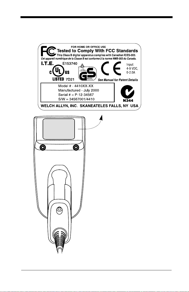
IT4410 Imager Identification
Enlarged View of Label
1 - 4
Hand Held IT4410 Imager
Bottom View
Page 17

IT4710 Imager Identification
Hand Held IT4710 Imager
Bottom View
1 - 5
Page 18

Connecting the Scanner in Keyboard Wedge Mode
A scanner can be connected between the keyboard and PC as a “keyboard
wedge,” plugged into the serial port, or connected to a portable data term in al in
non decoded output mode.
Note: The IMAGETEAM 4410 and 471 0 scanners are factory programmed for a
keyboard wedge interface to an IBM PC AT with a USA keyboard.
The following is an example of a keyboard wedge connection:
1. Turn off power to the terminal/computer.
2. Disconnect the keyboard cable from
the back of the terminal/computer.
Disconnect
3. Connect the appropriate interface cable to
the scanner and to the
terminal/
computer. The scanner will beep twice.
4. Connect the power
supply (4 to 9V).
5. Turn the terminal/computer power back on.
6. Verify the scanner
operation by sc ann ing
a bar code. The scanner will beep once.
1
3
2
4
The scanner is now conne cted and ready to communicate w ith your terminal/PC.
You must program the scanner for your interface before bar code data can be
transmitted to your terminal/PC. If you are using the scanner as a keyboard
wedge, see"Terminal Interface" on page 2-4. If the scanner is connected via a
serial port, turn to "Connecting the Scanner to a Serial Port" on page 1-7.
1 - 6
Page 19

Connecting the Scanner to a Serial Port
Turn off power to the terminal/computer.
1. Connect the interface cable to the scanner
2. Connect the interface cable to the 4 to 9 volt power supply and plug in the
power supply. The scanner will beep twice.
3. Connect the interface cable to the terminal/com pu ter.
2
Power Supply
3
Interface Cable
1
4. Turn the terminal/computer power back on.
5. Verify the scanner operation by scanning a bar code from the back cover of
this manual. The scanner will beep once.
The scanner is now conne cted and ready to communicate w ith your terminal/PC.
Turn to "Communica tio n Settings" on page 2-10 to program the commun ic ati on
parameters for a serial interface.
1 - 7
Page 20

Reading Techniques
The hand-held Imager has a view finder that projects a bright red aiming beam
that corresponds to the Imager’s horizontal field of view. The aiming beam
should be centered ov er the bar code, but it c an be positioned in any direction for
a good read.
Linear bar code 2D Matrix symbol
The aiming beam is smaller when the Imager is closer to the code and larger
when it is farther fro m the co de. Symbolog ies wi th smaller ba rs or elem ents (mi l
size) should be read clos er to the unit. Symbologi es with larger bars or el ements
(mil size) should be read fa rther from the unit. (see "Depth of Field Charts (44 10
& 4710)" on page 10-4.) To r ead s ingle or mu ltiple symbo ls (on a pa ge or on an
object), hold the Imager at an appropriate distance from the target, pull the
trigger, and center the aiming beam on the symbol.
1 - 8
Page 21

2
Programming
Introduction
Use this section to program the hand-held or fixed mount Imager.
This programming section contains the following menuing selections:
• General Selections
• Terminal Interface Selections
• Keyboard Selections
• Communication Settings
• Imager Selections
• Output Selections
• Prefix/Suffix Selections
• Data Formatter Selections
• Output Sequence Selections
2 - 1
Page 22

Reset Factory Settings
All operating parameters are stored in nonvolatile memory resident in the
Imager, where they are permanently retained in the event of a powe r interruption.
When you receive your Imager, ce rtain operating paramet ers have already been
set. These are the factory defaults, indicated by the symbol “✱” on the
programming menu pages (beneath the default programming symbol). Default
charts begin on page 5-1.
Default
Status Check
Read the
level to the host terminal. The software revision will be printed out as
“REV_SW:$ProjectRevision:1.xx$;REV_WA:31204960-xxx.”
Read the
Editor formats. One format per line will be printed out.
Show Software
Show Software Revision
Show Data Formats
Revision
symbol to transmit the software revision
symbol to transmit the existing Data Format
Show Data Formats
All Symbologies
If you want to decode all the symbologies allowable for your scanner, scan the
All Symbologies On
All Symbologies
On
code.
All Symbologies
Off
2 - 2
Page 23

Revision Selections
Both the follow ing programming c odes would n ot normally be ne eded unless you
have a problem with the unit. An Application Support Representative may
request the boo t code or power PC rev ision in format ion i n or der to trouble shoot
a problem.
Boot Code RevisionPower PC Revision
2 - 3
Page 24

Terminal Interface
IMAGETEAM 4410 and IMAGETEAM 4710 scanners are factory programmed
for a keyboard wedge interface to an IBM PC AT with a USA keyboard. If this is
your interface and yo u do no t need to mo dify the sett ings, ski p to "Power Sav ing
Mode" on page 2-16 to begin programming the scanner.
If your interface is not a standard PC AT, refer to the "Supported Terminals
Chart" on page 2-5 and locate the Terminal ID number for your PC. Scan the
Terminal ID bar code below, then scan the numeric bar code(s) on the inside
back cover of this manual to program the scanner for your terminal ID> Scan
Save to save your selection.
For example, an IBM PS/2 terminal has a Terminal ID of 002. You would scan
the Terminal ID b ar code , then 0, 0, 2 from the inside back cover, then Save. If
you make an error while scanning the digits (before scanning Save), scan the
Discard code on the back cover and scan the digits and the Save code again.
Factory Default for Keyboard Wedge units = 003
Factory Default for True RS-232 units = 000
Terminal ID Save
2 - 4
Page 25

Supported Terminals Chart
Terminal Model(s)
DEC PC433 SE (Portable PC) 003
DELL Latitude (Portable PC) 003
DTK 486 SLC (Portable PC) 003
Fujitsu Stylistic (Portable PC) 003
HHLC (Code 128 Emulation) 089
IBM PC XT 001
IBM PS/2 25, 30, 77DX2 002
IBM
IBM
IBM
IBM
IBM AT Thinkpad 106
Midwest Micro Elite TS 30 PS (Portable PC) 003
Mitak 4022 (Portable PC) 003
Olivetti M19, M24, M28, M200 001
Olivetti M240, M250, M290, M380, P500 003
Reliasys TR 175 003
RS-232 TTL 000
Televideo 990, 995, 9060 002
Texas Instruments Extensa 560CD (Portable PC) 003
Toshiba 2600 (Portable PC) 003
Toshiba Satellite T1960, T2130, CS (Portable PC) 003
Zenith Z-note (Portable PC) 003
AT, PS/2 30-286, 50, 55SX, 60, 70,
70-061, 70 -121, 80
AT Compatibles Keyboard Emulation
(Non-wedge)
Thinkpad 360 CSE, 34, 750
(Portable PC)
Thinkpad 365, 755 CV
(Portable PC)
Terminal
I.D.
003
003
097
003
2 - 5
Page 26

Keyboard Country
Scan the Program Keyboard Country bar code below, then scan the numeric
bar code(s) from the inside back cover, then the Save bar code to program the
keyboard for your country. As a general rule, the following characters are not
supported by the scanner for countri es othe r than the Unite d States :
@ | $ # { } [ ] = / ‘ \ < > ~
Keyboard Country
Country Code Scan Country Code Scan
Belgium.....................1 Latin America.........14
Czechoslovakia........15 Norway...................9
Denmark................... 8 Poland....................20
Finland...................... 2 Portugal .................13
France ......................3 Romania ................25
French Canadian...... 18 Russia....................26
Germany/Austria.......4 Slovakia.................22
Great Britain .............7 Spain......................10
Greece...................... 17 Sweden..................23
Netherlands.............. 11 Switzerland............6
Hungary.................... 19 Turkey Q................24
Israel......................... 12 Turkey F.................27
Italy...........................5 USA
(Default)
.........0
2 - 6
Save
Page 27

Keyboard Style
This programs keyboard styles, such as Caps Lock and Shift Lock.
Regular.
Regular
Caps Lock
Shift Lock
to U.S. keyboards.)
Automatic Caps Lock
software tracks and reflec ts if yo u have Caps Loc k on o r off (AT and PS/2 o nly).
This selection c an only be used with sys tems t hat hav e an LED which no tes the
Caps Lock status.
is used when you normally have the Caps Lock key off.
is used when you normally have the Caps Lock key on.
is used when you normally h ave the Shift Lock key on. (Not com mon
is used if you change the Cap s Lock key on and o ff. The
* Regular
Shift Lock
Default =
Caps Lock
Automatic
Caps Lock
Emulate External Keyboard
keyboard (IBM AT or equivalent). To connect to a laptop, you must scan the
Emulate External Keyboard bar code below, then scan "Automatic Direct
Connect Mode On " on page 2-8. A fter sc ann ing these codes, yo u m ust re -boo t
your laptop.
should be scann ed if you do not ha ve an external
Emulate External
Keyboard
2 - 7
Page 28

Keyboard Modifiers
This modifies s pecial keybo ard features, s uch as CTRL+ ASCII codes and Turbo
Mode.
Control + ASCII Mode On
control characters for values 00-1F. Refer to "Keyboard Function
Relationships"on page 2-9 for CTRL+ ASCII Values.
Control + ASCII
Mode On
Turbo Mode
use with IBM AT only.) If the terminal drops characters , do not use Turbo Mode.
- The scanner sends characters to an IBM AT te rminal fa ster. (For
- The scanner sends key combinations for ASCII
Default = Off
* Control + ASCII
Mode Off
Default = Off
Turbo Mode On
Numeric Keypad Mode
numeric keypad.
Numeric Keyp ad
Mode On
Default = Off
- Sends numeric characters as if entered from a
* Turbo Mode Off
* Numeric
Keypad Mode Off
Automatic Direct Connect
keyboard is disabled when you plug in the scanner. This selection can also be
used if you have an IBM AT style terminal and the sys tem is dropping characters.
After scanning these codes, you must re-boot your computer.
Automatic Direct
Connect Mode On
- Use this selec tio n i f y ou are using a laptop wh ose
Default = Off
* Automatic Direct
Connect Mode Off
2 - 8
Page 29

Keyboard Function Relationships
The following Keyboard Function Code, Hex/ASCII Value, and Full ASCII
“CTRL”+ relationships apply to all terminals that can be used with the scanner.
Function Code HEX/ASCII Value Full ASCII “CTRL” +
NUL 00 2
SOH 01 A
STX 02 B
ETX 03 C
EOT 04 D
ENQ 05 E
ACK 06 F
BEL 07 G
BS 08 H
HT 09 I
LF 0A J
VT 0B K
FF 0C L
CR 0D M
SO 0E N
SI 0F O
DLE 10 P
DC1 11 Q
DC2 12 R
DC3 13 S
DC4 14 T
NAK 15 U
SYN 16 V
ETB 17 W
CAN 18 X
EM 19 Y
SUB 1A Z
ESC 1B [
FS 1C \
GS 1D ]
RS 1E 6
US 1F -
2 - 9
Page 30

Communication Settings
<Default All RS-232 Communication Settings>
Parity
Parity provides a means of checking character bit patterns for validity. The
Imager can be configured to operate under
(
None
) parity options. The host terminal must be set up for the same parity as
the Imager, to ensure reliable com munication.
Mark, Space, Odd, Even
SpaceMark
, or No
2 - 10
Odd
Even
* None
Page 31

Baud Rate
This sets the bau d rate from 30 0 bits per sec ond to 115,2 00 bits per second (see
next page). Progra mmin g b aud rate causes the data to be se nt a t th e s pe cified
rate. The host terminal must be set to the same baud rate as the Imager to
ensure reliable communication.
300 600
1200
19200
2400
96004800
* 38400
2 - 11
Page 32

Baud Rate, continued
57600 115200
Word Length Data Bits
You can set the Word Length at 7 or 8 bits of data per character. If an appl ication
requires only ASCII Hex characters 0 through 7F decimal (text, digits, and
punctuation), select 7 data bits. For applications requiring use of the full ASCII
set, select 8 data bits per character.
7 Data Bits
Word Length Stop Bits
Word Length can be set to one or two stop bits.
* 1 Stop Bit
* 8 Data Bits
2 Stop Bits
2 - 12
Page 33

Hardware Flow Control
When hardware flow cont rol is On, the software checks for a CTS s ign al b efo re
sending data. This option is useful when your application supports the CTS
signal.
On
* Off
Software Flow Control
This allows control of data transmission from the Imager using software
commands from the host device. When this feature is turned
control is used. When Data Flow Control is turned On, the host device su spends
transmission by sending the XOFF character (DC3, hex 13) to the Imager. To
resume transmission, the host sends the XON character (DC1, hex 11). Data
transmission continues where it left off when XOFF was sent.
On
Off
, no data flow
* Off
2 - 13
Page 34

Serial Triggering
This provides a means of sending a serial trigger command to start and stop
decoding. When this feature is turned
trigger commands. When serial triggering is turned On, the Imager requires a
serial trigger character to activate scan ning and decoding . The unit continue s to
scan and decode un til the
occurs, or a bar code is deco ded.
On the "Decimal to Hex to ASCII Conversion Chart"on page 2-36, find the hex
characters you want to use to turn the trigger on and off. Locate the decimal
values for those characters and scan the 2 digits for each one from the
Programming Chart in t he back of this manual.
When Serial Triggerin g is On, the default Trigger On decimal character is 18 (he x
12, DC2), and the default Trigger Off decimal character is 20 (hex 14, DC4).
Trigger Off
Off
, the Imager will not respond to serial
character turns off the s canner, a time o ut
* OffOn
Trigger On ‡
* Trigger Defaults
‡ A one to three digit decimal number and Save are required after reading
this programming symbol. See "Decimal to Hex to ASCII Conversion
Chart" on page 2-36, and the Programming Chart (inside back cover).
Trigger Off ‡
2 - 14
Page 35

Trigger Timeout
Use this selection to set a timeout (in quarter seconds) of the Imager’s trigger.
Once the imager has timed out, it must be triggered again either serially (see
"Serial Triggering"on page 2-14), or ma nually . Set the Trig ger Time out to 00 if
you don’t want a Trigger Timeout.
‡ A one- to three digit number and Save are required after reading this
programming symbol. Refer to the Programming Chart (inside back
cover).
Default setting = 120 seconds
Set Timeout ‡
2 - 15
Page 36

Power Saving Mode
This provides control of the Imager’s powe r cons um ptio n, as fol lows :
Low Power
read attempt
movement during the rea d attem pt, an d pow ers down after t he im age c apture is
complete.
Medium Power
enhances motion tolerance.
trigger is pulled, going into a “doze” (low power) state after each read attempt.
The Imager powers down ten seconds after the image capture is complete.
Normal Power
trigger is pulled or a decode is in process. The Imager doesn’t go into a “doze”
state after each read attempt, but will power down after two minutes if Power
Hold Mode is turned Off.
draws low (50%) LED current during image capture, allowing one
only
for each trigger pull. The Imager is less tolerant of hand
draws a normal LED current during image capture which
draws a normal LED current, attempting to read as long as the
Low Power Medium Power
Medium Power
attempts to read as long as the
2 - 16
* Normal Power
Page 37

Power Hold Mode
Power Hold On keeps the Imager in a ready to read st ate . To con ser ve power,
this selection may be tu rned
two minutes. When you are ready to use the Imager again, restore power by
pressing the trigger.
On * Off
Off
and the unit will power down if not used within
LED Power Level
This selection allows you to adjust LED brightness.
Off
is used when no illumination is needed.
sufficient.
High
(the default) is the brightest setting.
Low
is used if low illumination is
Off
Low
* High
2 - 17
Page 38

LED Flashing
When LED Flashing is On, the LEDs and aiming light alternately flash until a
symbol is decoded or the trigger is released.
If LED Flashing is turned
aiming light won’t illuminate while the scanner reads a bar code. The LEDs
remain on while the scanner is reading.
Off * On
Off
, the average current draw is increased and the
Aimer Delay
The aimer delay allows a delay time for the operator to aim the scanner before
the picture is taken. Use these codes to set the time between when the trigger
is pulled and when the picture is taken. During the delay time, the aiming light
will appear, but the LEDs won’t turn on until the delay time is over.
200 milliseconds
400 milliseconds
2 - 18
* Off
(no delay)
Page 39

Aimer Interval
Aimer Interval turns off the aiming light, or programs the aimer to come on at
certain interval s when readin g sy mbols wi th the scan ner. Yo u may progr am the
scanner to use the aimer
Read
. You may also program the scanner to use the aimer every “x” reads, by
entering a number from 0 to 999 to indicate “x.”
Every Read, Every Second Read
, or
Every Third
* Every ReadOff
Every Second Read
Every “x” Reads
‡ A one- to three digit number and Save are required after reading this
programming symbol. Refer to the Programming Chart (inside back
cover).
‡
Every Third Read
2 - 19
Page 40

Centering
Use the centering feature to narro w the ima ge r’s field of view to ma ke su re tha t
the imager reads only those bar codes intended by the user. For instance, if
multiple codes are placed closely together, centering will insure that only the
desired codes are read. When centering is turned on, the imager only reads
codes that intersect the centering window set up by the user. The centering
window must intersect the center of the image. If a bar code is not within the
predefined window, it will not be decoded or output by the scanner.
If centering is turn ed on by scanning the O n bar code below, the de fault centering
window is a 60 pixel square area in the cen ter of the imager ’s field of view. The
position of the window may be changed by scanning the top, bottom, left, and
right centering ba r codes that fol low and the app ropriate pixel value, if othe r than
the default, from the Pr ogramming Chart in the back of thi s manual. The defa ults
are listed in the table below.
Window Position Default Minimum Maximum Serial Command
Top of centering
window
Bottom of centering window
Left of centering
window
Right of centering
window
210 000 239 DECTPYxxx
270 240 479 DECBTYxxx
290 0 319 DECTPXxxx
350 320 639 DECBTXxxx
The centering function can be used in conjunction with the Aimer Delay feature
(page 2-18) for the most error-free operation in applications where multiple
codes are spaced closely together. Using the Aimer Delay and Centering
features, the ima ger can emulate the operatio n o f ol der sy ste ms, s uch as l ine ar
laser bar code scanners.
* OffOn
2 - 20
Page 41

The figure below ill ustrates the defau lt top, bottom , left, and right p ixel positions .
The position of the pixels is measured from the top and the left side of the
imager’s field of view with the field of view being 640 by 480 pixels.
290 350
0
640
Top
210
270
480
Left
Right
Bottom
Default
Center
2 - 21
Page 42

Top of Centering
Window
Top of Centering Window
Default (210)
Bottom of Centering
Window
Left of Centering
Window
Right of Centering
Window
Bottom of Centering
Window Default (270)
Left of Centering
Window Default (290)
Right of Centering
Window Default (350)
2 - 22
Page 43

In the example below, the gray area is the full im ager fie ld of view an d the white
area is the centering windo w. Bar Code 1 will not be rea d, while Bar Code 2 will
be.
Bar Code 1
Bar Code 2
2 - 23
Page 44

AutoTrigger
Two AutoTrigger Modes are available: Scan Stand and Presentation Mode.
When a unit is in Scan Stand mode, it remains idle as long as it sees the Scan
Stand symbol. (See Scan Stand Sy mbol th at foll ows .) Whe n a di fferent code is
presented, the Imager is triggered to read the new code.
Note: The scanner auto matically adjus ts the illumi nation LEDs to the lowest ligh t
level possible to mainta in a good loc k on the Sca n Stand sy mb ol.
Presentation mode is for those applicati ons where a scan stand will not work, i.e .,
when large pack ages mus t be sc anned. T o progr am the de vice fo r presenta tion
mode, refer to "Presentation Mode" on page 2-25.
Scan Stand
This selection programs the Imager to work in a Scan Stand.
On* Off
Scan Stand Symbol
When a unit is in Scan Stand mode, the LEDs shine at the Scan Stand symbol
on the base of the stand which tells it to remain idle. When the Scan Stand
symbol is covered, the imager turns the LEDs on at the con fig ured powe r leve l
(Default High) and attempts to find and decode bar codes in its field of view.
2 - 24
Scan Stand
Symbol
Page 45

Presentation Mode
This programs the scanner to work in Presentation Mode.
On* Off
Presentation Re-trigger Delay
This sets the time period before the scanner can re-trigger for another read
attempt. Setting a re-trigger delay protects against accidental rereads of the
same bar code. Longer delays are effectiv e in minim izin g accident al rereads at
POS (point of sale). Use shorter delays in app lications where rep etitive bar code
scanning is required. Entries are in milliseconds, up to 10,000.
Default = 500.
Presentation Re-trigger Delay
Presentation Lights
When using the scanner in presentation mode, the illuminating LEDs can be
programmed on or off. If there is sufficient ambient light, the LEDs can be turned
off by scanning the Lights Off bar c ode be low. When a bar co de is p resent ed to
the scanner, the illu minating LEDs turn on to scan the bar code an d then turn o ff
when the bar code has been read.
Default = Presentation Mode Lights On
.
* On
Presentation Default
Defaults all presentation mode settings.
Presentation Reread Delay 200 ms.
Presentation Default
Defaults
Off
=
Presentation Mode Off,
2 - 25
Page 46

Beeper Volume
Off
Medium
Power Up Beeper
* On
Output Sequence Beeper
Low
* High
Off
If you are using an O utput Sequence (see " Output Sequence Overview" on page
2-43), you may want to hear a beep after each bar code as it is read. Scan
Output Sequence Beeper On to enable this feature, or
* On
Off
to disable it.
Off
2 - 26
Page 47

Beep On Decode
If you want the s ca nn er t o b eep each time it rea ds a ba r c ode , l eav e this s ett ing
On
. If you don’t want it to beep on each read, but do want it to beep for other
events, such as error conditions, set this selection to
Off
.
* On
Beeper Default
Defaults all beeper s ettings.
On, Output Sequence Beeper On, Beep On Read On.
Defaults
=
Beeper Default
Beeper Volume High, Power U p Beeper
Off
2 - 27
Page 48

Intercharacter, Interfunction, and Intermessage Delays
Some terminals drop informat ion (characte rs) if data com es through to o quickly.
Intercharacter, interfunction, and intermessage delays slow the transmission of
data increasing data integrity.
Each delay is composed of a 5 millisecond step. You can program up to 99 steps
(of 5 ms each).
Intercharacter Delay
Note: This selection is valid for keyboard wedge interfaces only.
This is a delay of up to 495 milliseconds (in multiples of 5) placed between the
transmission of e ach character of s canned data. You can program up to 99 st eps
(of 5 ms each). Scan the
number of steps, and the
Note:
If you make an error while scanning the digits (before scanning Save),
Discard
scan
again.
Intercharacter Delay
Save
bar code from the inside back cover.
on the back cover and scan the correct digits and
Prefix Scanned Data Suffix
1 2345
Intercharacter Delay
bar code below, then scan the
Save
Intercharacter Delay
To remove this delay, scan the
number of steps to 00. Scan the
Intercharacter Delay
Save
bar code from the inside back cover.
bar code, then set the
User Specified Intercharacter Delay
Note: This selection is valid for keyboard wedge interfaces only.
This is a delay of up to 495 milliseconds (in multiples of 5) placed after the
transmission of a particular character of scanned data. You can program up to
99 steps (of 5 ms each) to follow the character you specify. Scan the
Length
Save
bar code below, then scan the number of steps for the delay, and the
bar code from the inside back cover.
2 - 28
Delay
Page 49

Next, scan the
ASCII character that trigger the delay (refer to the "Decimal to Hex to ASCII
Conversion Chart" on page 2-36).
Note:
If you make an error while scanning the digits (before scanning Save),
scan
again.
Character to Trigger
Discard
on the back cover and scan the correct digits and
bar code, then the 2 di git hex value for the
Save
Delay Length
To remove this delay, scan the
steps to 00. Scan the
Save
bar code from the inside back cover.
Delay Length
Character to Trigger Delay
bar code, then set the number of
Interfunction Delay
Note: This selection is valid for keyboard wedge interfaces only.
This is a delay of up to 495 milliseconds (in multiples of 5) placed between the
transmission of e ach segmen t of the mess age s tring. You can pro gram u p to 9 9
steps (of 5 m s eac h). Sca n t he
the number of steps, and the
Note: If you make an error while scanning the digits (before scanning Save),
scan Discard on the back cover and scan the correct digits and Save
again.
Interfunction Delay
Save
bar code from the inside back cover.
Prefix Scanned Data Suffix
1 2345STX HT CR LF
Interfunction Delays
bar code below, then scan
Interfunction Delay
To remove this delay, scan the
number of steps to 00. Scan the
Interfunction Delay
Save
bar code from the inside back cover.
bar code, then set the
2 - 29
Page 50

Intermessage Delay
Note: This selection is valid for keyboard wedge interfaces only.
This is a delay o f up to 495 mill isecond s (in m ultip les o f 5) placed b etwee n eac h
scan transmission. You can program up to 99 steps (of 5 ms each). Scan the
Intermessage Delay
Save
bar code from the inside back cover.
Note:
If you make an error while scanning the digits (before scanning Save),
scan
Discard
again.
bar code below, then scan the number of steps, and the
on the back cover and scan the correct digits and
2nd Scan Transmission1st Scan Transmission
Intermessage Delay
Intermessage Delay
Save
To remove this delay, scan the
number of steps to 00. Scan the
2 - 30
Intermessage Delay
Save
bar code from the inside back cover.
bar code, then set the
Page 51

Prefix/Suffix Overview
When a bar code is scanned, ad ditional in formation is sent to the host co mputer
along with the bar code data. This group of bar code data and additional,
user-defined data is called a “message string.” The selections in this secti on are
used to build the user-defined data into the message string.
Prefix and Suffix characters are data characters that can be se nt before and after
scanned data. You can specify if they should be sent with all symbologies, or
only with specific symbologies. The following illustration shows the breakdown
of a message string:
Prefix Scanned Data Suffix
1-10
alpha
numeric
characters
variable
length
1-10
alpha
numeric
characters
Points to Keep In Mind
• It is not necessary to build a message string. The selections in this
chapter are only used if you wish to alter the default settings.
prefix = None. Default suffix = CR/LF
• A prefix or suffix may be added or cleared from one symbology or all
symbologies.
• You can add any prefix or suffix from the "Decimal to Hex to ASCII
Conversion Chart" on page 2-36, plus Code I.D. and Aim I.D.
• You can string together several entries for several symbologies at one
time.
• Enter prefixes and suffixe s in the order in which you want the m to appear
on the output.
.
Default
2 - 31
Page 52

Adding a Prefix or Suffix
1. Scan the
2. Determine the 2 digit Hex value from the "Symbology Chart" on page 2-35
for the symbology to which you want to apply the prefix or suffix.
3. Scan the 2 hex digits from the Programming Chart inside the back cover or
scan 9, 9 for all symbologies.
4. Determine the hex value from the "Decimal to Hex to ASCII Conversion
Chart" on page 2-36 for the prefix or suffix you wish to enter.
5. Scan the 2 digit hex value from the Programming Chart inside the back
cover.
Note:
Note:
6. Scan Save to exit and save, or scan Discard to exit without saving.
Repeat Steps 1-6 to add a prefix or suffix for another symbology.
Example: Add a Suffix to a specific symbology
To send a CR (carriage return)Suffix for UPC only:
1. Scan
2. Determine the 2 digit hex value from th e "Symbol ogy Chart"on page 2-35 for
UPC.
3. Scan
4. Determine the hex value from the "Decimal to Hex to ASCII Conversion
Chart" on page 2-36 for the CR (carriage return).
5. Scan
6. Scan
Add Prefix
Repeat Steps 4 and 5 for every prefix or suffix character.
To add the Code I.D., scan
To add AIM I.D., scan
To add a backslash (\), scan
Add Suffix
6, 3
from the Programming Chart (inside b ack cover).
0, D
from the Programming Chart (inside back cover).
Save
, or scan
(page 2-34) or
5, C, 8, 1
.
Discard
Add Suffix
5, C, 8, 0
.
.
symbol (page 2-34).
5, C, 5, C.
to exit without saving.
Clearing One or All Prefixes or Suffixes
You can clear a single prefix or suffix, or clear all prefixes/suffixes for a
symbology. When you Clear One Prefix (Suffix), the specific character you
select is deleted from the symbology you want. When you Clear All Prefixes
(Suffixes), all the prefixes or suffixes for a symbology are deleted.
1. Scan the
2. Determine the 2 digit Hex value from the "Symbology Chart" on page 2-35
for the symbology from which you want to clear the prefix or suffix.
3. Scan the 2 digit hex value from the Programming Chart inside the back cover
or scan
Your change is automatically saved.
2 - 32
Clear One Prefix
9, 9
for all symbologies.
symbol.
Page 53

Add a Carriage Return Suffix to All Symbologies
Scan the following bar code if you wish to add a Carriage Return Suffix to all
symbologies at onc e. Thi s actio n first clears all current su ffixes , then programs
a carriage return suffix for all symbologies.
Add CR/LR Suffix
All Symbologies
Add a Code I.D. Prefix to All Symbologies
This selection all ows you to turn on ( or off) transmission of a Code I.D. befo re the
decoded symbology. (See the "Symbology Chart" on page 2-35 for the single
character code that ide ntifies each symbology.) T his action first clears all cu rrent
prefixes, then programs a Code I.D. pr efix for all symbologies.
Add Code ID Prefix
All Symbologies
Add an AIM I.D. Prefix to All Symbologies
This selection allo ws you to turn on (or off ) transmission of an AIM I.D. before the
decoded symbology. (See the "Symbology Chart" on page 2-35 for the single
character code that ide ntifies each symbology.) T his action first clears all cu rrent
prefixes, then programs an AIM I.D. prefix for all symbologies.
Add AIM ID Prefix
All Symbologies
(See AIM Guidelines on Symbology Identifiers for more information on the AIM
symbology ID characters.)
2 - 33
Page 54

Prefix Entries
Add Prefix †
Suffix Entries
Add Suffix †
Clear One Prefix †
Clear All Prefixes
Clear One
Suffix †
Clear All Suffixes
† One or more two digit numbers and
programming symbol. Refer to the Programming Chart (inside back cover).
Save
are required after reading this
Exit Selections
Save Discard
2 - 34
Page 55

Symbology Chart
Symbology
Australian 4 State
Aztec Code
BC412**
BPO 4 State
Canadian 4 State
Codabar
Codablock-F
Code 11
Code 39
Code 49
Code 93
Code 128
Code Z**
Data Matrix
EAN
IATA 2 of 5
CodeIDAIMIDHex
ID
A]X41
z]z7A
g]X67
B]X42
C]X43
a]F61
q]O71
h]H068
b]A62
l]T6C
i]G69
j]C6A
u]X75
w]d77
d]E64
f]R66
Symbology
Interleaved 2 of 5
Japanese Postal
Kix (Dutch) Postal
Maxicode
Micro PDF417
MSI
No Read
OCR
PDF417
Planet Code
Postnet
QR Code
RSS/Composites
UPC
Vericode**
All Symbologies
CodeIDAIMIDHex
e]l65
J]X4A
K]X4B
x]U78
R]L52
g]M067
o]Y6F
r]L72
L]X4C
P]X50
s]Q73
y]e79
c]E63
v]V76
†
ID
9C
99
Note: Prefix/Suffix entries for specific symbologies override the universal (All
Symbologies, 99) entry.
†
All Symbologies: Prefix/Suffix programming only!
** Not available in standard product. Only available when ordered in custom
firmware
2 - 35
Page 56

Decimal to Hex to ASCII Conversion Chart
Dec. Hex ASCII Dec. Hex ASCII Dec. Hex ASCII Dec. Hex ASCII
0 00 NUL 32 20 SP 64 40 @ 96 60 ‘
1 01 SOH 33 21 ! 65 41 A 97 61 a
2 02 STX 34 22 “ 66 42 B 98 62 b
3 03 ETX 35 23 # 67 43 C 99 63 c
4 04EOT3624$ 6844D 10064d
5 05ENQ3725% 6945E 10165e
6 06ACK3826& 7046F 10266f
7 07 BEL 39 27 ‘ 71 47 G 103 67 g
8 08BS 4028( 7248H 10468h
9 09HT 4129) 7349l 10569i
10 0A LF 42 2A * 74 4A J 106 6A j
11 0B VT 43 2B + 75 4B K 107 6B k
12 0C FF 44 2C , 76 4C L 108 6C l
13 0D CR 45 2D - 77 4D M 109 6D m
14 0E SO 46 2E . 78 4E N 110 6E n
15 0F SI 47 2F / 79 4F O 111 6F o
16 10 DLE 48 30 0 80 50 P 112 70 p
17 11 DC1 49 31 1 81 51 Q 113 71 q
18 12 DC2 50 32 2 82 52 R 114 72 r
19 13 DC3 51 33 3 83 53 S 115 73 s
20 14 DC4 52 34 4 84 54 T 116 74 t
21 15 NAK 53 35 5 85 55 U 117 75 u
22 16 SYN 54 36 6 86 56 V 118 76 v
23 17 ETB 55 37 7 87 57 W 119 77 w
24 18 CAN 56 38 8 88 58 X 120 78 x
25 19 EM 57 39 9 89 59 Y 121 79 y
26 1A SUB 58 3A : 90 5A Z 122 7A z
27 1B ESC 59 3B ; 91 5B [ 123 7B {
28 1C FS 60 3C < 92 5C \ 124 7C |
29 1D GS 61 3D = 93 5D ] 125 7D }
30 1E RS 62 3E > 94 5E ^ 126 7E ~
31 1F US 63 3F ? 95 5F _ 127 7F DEL
2 - 36
Page 57

Data Format Editor Overview
The Data Format Editor selec tions are used to edi t scanned data. For exa mple,
you can use the Data Format Editor to insert characters at certain points in bar
code data as it is scanned.
It is not necessary to use the Data Format Editor. A set of defaults for the data
format is already programmed in the scanner. The selections in the following
pages are used only if you w ish to alter the default settin gs.
setting = none.
If you have change d data format sett ings, and wish to clear all forma ts and return
to the defaults, scan the Default Data Format code.
To Add a Data Format
Default Data Format
1. Scan the
2. Primary/Alternate Format
Determine if this will be your primary data format, or one of 3 alternate formats. (Alternate formats allow you “single shot” capability to scan one bar
code using a different data format. After the one bar code has been read,
the scanner reverts to the primary data format. See "Alternate Data
Formats" on page 2-42.) If you are program ming the primary format, scan 0.
If you are programming an alternate format, scan
the alternate format you are programming.
3. Terminal Type
Refer to the "Supported Terminals Chart" on page 2-5 and locate the Terminal ID number for your PC. Scan th ree nume ric bar c odes on the insi de back
cover to program the scanner for your terminal ID (you must enter 3 digits).
For example, scan
4. Code I.D.
On page 2-35, find the symbology to which you want to apply the data format. Locate the Hex valu e for tha t sym bolog y and s can t he 2 di git hex valu e
from the Programming Chart.
5. Length
Specify what length (up to 9999 ch aracters) of data will be acceptable for this
symbology. Scan the four digit data length from the Programming Chart.
(Note: 50 characters is entered as 0050. 9999 is a universal number, indicating all lengths.)
6. Editor Commands
Refer to the "Format Editor Commands" on page 2-38. Scan the symbols
that represent the co mm an d you want to enter . 9 4 alphanumeric characters
may be entered for each symbology data format.
7. Scan
Enter Data Format
0 0 3
Save
to save your entries.
symbol (page 2-40).
for an AT wedge.
1, 2
, or 3, depending on
2 - 37
Page 58

Other Programming Selections
• Clear One Data Format
This deletes one data format for one symbology. If you are clearing the
primary format, scan 0. If you are clearing an al ternate format , scan 1, 2,
or 3, depending on the alternate format you are clearing. Scan the
Terminal Type (refer to the "Supported Terminals Chart" on page 2-5),
Code I.D. and the length of the format you want to delete. That length
data format for that symbology is deleted and all other formats are
unaffected.
• Save
This exits, saving any Data Format changes.
• Discard
This exits without saving any Data Format changes.
Format Editor Commands
Send Commands
F1 Send all characters followed by “xx” key or function code, sta r tin g from
current cursor position.
ASCII code, see "Decimal to Hex to ASCII Conversion Chart"on page 2-
36.)
F2 Send “nn” characters followed by “xx” key or function code, starting from
current curs or position.
value (00-99) for the number of c haracters a nd xx stands for the hex value
for an ASCII code. See "Decimal to Hex to ASCII Conversion Chart" on
page 2-36.)
F3 Send up to but not including “ss” character (Search and Send) starting
from current cursor position, leaving cursor pointing to “ss” character
followed by “xx” key or function code.
stand for the hex values for ASCII codes, see "Decimal to Hex to ASCII
Conversion Chart"on page 2-36.)
F4 Send “xx” character “nn” times (Insert) leaving cursor in current cursor
position.
see "Decimal to He x to ASCII Conversion Chart" on page 2-36, and nn is
the numeric value (00-99) for the number of times it should be sent.)
E9 Send all but the last “nn” characters, starting from the current curso r
position.
of characters that will not be sent at the end of the message.)
Move Command s
F5 Move the cursor ahead “nn” characters from current cursor position.
Syntax = F4xxnn
Syntax = E9nn
Syntax = F5nn
of characters the cursor should be moved ahead.)
F6 Move the cursor back “nn” characters from current cursor position.
Syntax = F6nn
of characters the cursor should be moved back.)
F7 Move the cursor to the beginning of the data string.
EA Move the cursor to the end of the data string.
Syntax = F1xx
Syntax = F2nnxx
(xx stands for the hex value for an ASCII code,
(nn is the numeric value (00-99 ) for the numb er
(nn stands for the numeric value (00-99) for the number
(nn stands for the numeric value (00-99) for the number
(xx stands for the hex valu e for an
(nn stands for the numeric
Syntax = F3ssxx
(ss and xx both
Syntax = F7.
Syntax = EA
2 - 38
Page 59

Search Commands
F8 Search ahead for “xx” character from current cursor position, leaving
cursor pointing to “xx” character.
Syntax = F8xx
(xx stands for the hex
value for an ASCII code, see "Decimal to Hex to ASCII Conversion
Chart" on page 2-36.)
F9 Search back for “xx” character from current cursor po sition, leav ing cursor
pointing to “xx” character.
Syntax = F9xx
(xx stands for the hex v alue for
an ASCII code, see "Deci mal to He x to ASCII C onver sion Cha rt"on page
2-36.)
E6 Search ahead for the first non “xx” characte r from the cur rent cursor
position, leaving cursor pointing to non ”xx” character.
Syntax = E6xx
stands for the hex valu e for an ASCII co de, see "Dec imal to Hex to AS CII
Conversion Chart"on page 2-36.)
E7 Search back for the first non “xx” character from the current cursor
position, leaving cursor pointing to non ”xx” character.
Syntax = E7xx
stands for the hex valu e for an ASCII co de, see "Dec imal to Hex to AS CII
Conversion Chart"on page 2-36.)
Miscellaneous Commands
FB Suppress all occurrences of up to 15 different characters, starting at the
current cursor position, as the cursor is advanced by other commands.
When the FC command is encountered, the suppress function is
terminated. The cursor is not moved by the FB command. Syntax =
FBnnxxyy . .zz where nn is a c ount of th e number suppress characters in
the list and xxyy .. zz is the list of cha racters to be supp resse d. (xx st and s
for the hex value for an ASCII code, see "Decimal to Hex to ASCII
Conversion Chart"on page 2-36.)
FC Disable suppress filter and clear al l suppress ed charac ters.
Syntax = FC.
E4 Replaces up to 15 characters in the data string with user specified
characters. Replacement continues until the E5 command is
encountered.
Syntax = E4nnxx1xx2yy1yy2...zz1zz
where nn is the total
2
count of both characte rs to be repl ac ed p lu s re pla ce me nt characters; xx
defines characters to be replaced and xx
characters, continuing through zz
1
E5 Terminates character replacement.
defines replacement
2
and zz2.
Syntax = E5.
FE Compare character in current cursor position to the character “xx.” If
characters are equal, increment cursor. If characters are not equal, no
format match.
Syntax = FExx
(xx stands for the hex value for an ASCII
code, see "Decimal to Hex to ASCII Conversion Chart" on page 2-36.)
EC Check to make sure there is an ASCII number at the current cursor
position. If character is not numeric, format is aborted.
Syntax = EC
ED Check to make sure there is a non-numeric ASCII charac ter at the current
cursor position. If character is numeric, format is aborted.
Syntax = ED
(xx
(xx
.
1
.
2 - 39
Page 60

Data Format Editor
See page 2-37 through page 2-39 for a des cription of Data Format selection s and
commands.
Enter Data Format † Default
Clear One
Data Format †
Data Format
(none)
Clear All
Data Formats
Exit Selections
Save Current
Data Format Changes
Discard Current
Data Format Changes
† One or more two digit numbers and
programming symbol. Refer to the Programming Chart (inside back cover).
Save
are required after reading this
2 - 40
Page 61

Data Formatter
When Data Formatter is turned off, the bar code data is output to the host as read
(including prefixes and suffixes).
* On/Not Required Off
Require Data Format
When Data Formatter is
format or the scanner does not transmit the input data to the host device.
Required
, all input data must conform to an edited
Required
Show Data Formats
Read the
One format per line is printed out.
Show Data Formats
bar code to transmit the existing data formats.
Show Data Formats
2 - 41
Page 62

Alternate Data Formats
Alternate formats allow you “single s hot” capab ility to scan one ba r code usin g a
different data format than your primary format. When data formats are
programmed (see pa ge 2-37), y ou must input wheth er you are programming the
primary format, or an alternate format numbered 1, 2, or 3.
An alternate format is initiated by scanning one of the 3 alternate format bar
codes below. The scanne r wi ll s can the n ext bar code, formatting the dat a with
the selected alternate format, then revert immediately to the primary format.
Alternate
Data Format 1
Alternate
Data Format 2
Alternate Data Format 3
2 - 42
Page 63

Output Sequence Overview
Require Output Sequence
When turned off, the bar code data will be output to the host as the Imager
decodes it. When tu rned on, all output da ta must conform to an ed ited sequence
or the Imager will not transmit the output data to the host device.
Note: This selection is unavailable when the Multiple Symbols Selection is
turned on.
Output Sequence Editor
This programming selection allows you to program the Imager to output data
(when scanning more than one symbol) in whatever order your application
requires, regardless of the order in which the bar codes are scanned. Reading
the
Default Sequence
shown below. These are the defaults . Be certain you want to del ete or clear a ll
formats before you read the
Note: To make Output Sequence Edi tor selections, you’ll need to know the code
I.D., code length, an d charact er match(e s) your ap plication re quires. Us e
the Alphanumeric symbols (inside back cover) to read these options.
To Add an Output Sequence
symbol programs the Imager to the Universal values,
Default Sequence
symbol.
1. Scan the
2-46).
2. Code I.D.
On the "Symbology Chart" on page 2-35, find the symbology to which you
want to apply the output sequence format. Locate the Hex value for that
symbology and scan the 2 digit hex value from the Programming Chart
(inside back cover).
3. Length
Specify what length (up to 999 9 characters) of dat a output will be ac ceptable
for this symbology. Scan the four digit data length from the Programming
Chart. (Note: 50 characters is entered as 0050. 9999 is a universal number, indicating all lengths.)
4. Character Match Sequences
On the "Decimal to Hex to ASCII Conversion Chart" on page 2-36, find the
Hex value that represents the character(s) you want to match. Use the Programming Chart to read the alphanumeric combination that represents the
ASCII characters. (99 is the Universal number, indicating all characters.)
5. End Output Sequence Editor
Scan
Current Output Sequence Changes
Enter Sequence
F F
to enter an Output Sequence for an ad dition al sym bology , or
symbol (see "Output Sequence Editor" on page
to save your entries.
Other Programming Selecti ons
•
Discard Current Output Sequence Changes
This exits without saving any Output Sequence changes.
Save
2 - 43
Page 64

Output Sequence Example
In this example, y ou are s ca nni ng C ode 93 , C od e 1 28, an d C od e 3 9 b ar cod es ,
but you want the scanner to output Code 39 1st, Code 128 2nd, and Code 93
3rd, as shown below.
Note: Code 93 must be enabled to use this example.
A - Code 39
B - Code 128
C - Code 93
You would set up the sequence editor with the following command line:
SEQBLK62999941FF6A999942FF69999943FF
The breakdown of the command line is shown below:
SEQBLKsequence editor start command
62 code identifier for Code 39
9999code length that must match for Code 39, 9999 = all lengths
41 start character match for Code 39, 41h = “A”
FF termination string for first code
6A code identifier for Code 128
9999code length that must match for Code 128, 9999 = all lengths
42 start character match for Code 128, 42h = “B”
FF termination string for second code
69 code identifier for Code 93
9999code length that must match for Code 93, 9999 = all lengths
43 start character match for Code 93, 43h = “C”
FF termination string for third code
2 - 44
Page 65

Require Output Sequence
When an output se quence is
sequence or the scanner will not transmit the output data to the host device.
When it’s
conform to an edited sequ en ce, but if it cannot, the scann er tran sm its all outp ut
data to the host device as is.
When the output seq uen ce is
scanner decodes it.
Note: This selection is unavailable when the Multiple Symbols Selection is
On/Not Required
turned on.
Required On/Not Requi red
Required
, the scanner will attempt to get the output data to
Off
, all output data m ust conform to an ed ited
, the bar code data is o utpu t to t he h ost as the
Off
2 - 45
Page 66

Output Sequence Editor
Enter Sequence † Default Sequence
Exit Selections
Save Current
Output Sequence Changes
Discard Current
Output Sequence Changes
Note: If you want the scanner to beep after each bar code is read, please see
"Output Sequence Beeper"on page 2-26.
† One or more two digit numbers and Save are required after reading this
programming symbol. Refer to the Programming Chart (inside back cover).
2 - 46
Page 67

Multiple Symbols
Note: This feature does not work when the Imager is in Low Power mode.
When this programming selection is turned On, it allows you to read multiple
symbols with a single pull of the Imager’s trigger. If you press and hold the
trigger, aiming the Imager at a s eries of sy mbols, it reads un ique symbo ls once,
beeping (if turned on) for each read. The imager attempts to find and decode
new symbols as lon g as the trigger is pulled. When th is pro gram m ing se lec tion
is turned
Off
, the Imager will only read the symbol closest to the aiming beam.
On
* Off
No Read
With No Read turned On, the Imager notifies you if a code cannot be read. In
the Quick*View Scan Data Window (see "Scan Data Window"on page 7-4), an
“NR” appears when a code cannot be read. If No Read is turned
will not appear.
On
If you want a different notation than “NR,” for example, “Error,” or “Bad Code,”
you can edit the o utput mess age using t he Data Format ter (see page 2-37). The
hex code for the No Read symbol is 9C.
Off
, the “NR”
* Off
2 - 47
Page 68

Print Weight
Print Weight is used to adjust the way the scanner reads Matrix symbols. If a
scanner will be seeing consistently heavily printed matrix symbols, then a print
weight of 6 may improve th e reading performance. For con sistently light printing,
a print weight of 2 m ay he lp. A v alue fr om 0 to 7 may be us ed to a djust the prin t
weight. The default print weight is 4.
† Set Print Weight
† A one digit number from 1 to 7 is required after reading this programming
symbol. Refer to the Programming Chart (inside back cover).
* Default
Function Code Transmit
When this selection is enabled and function codes are contained within the
scanned data, the scan ner transmits th e function code to the terminal. Charts of
these function codes are provided in Chapter 9, Supported Interface Keys.
When the scanner is in key bo ard wedge mod e, the sc an c ode is conv erte d to a
key code before it is transmitted.
* On
Off
2 - 48
Page 69

Video Reverse
Video Reverse is used to allow the imager to read barcodes that are inverted.
The “Off” bar code below is an example of this type of bar code. If additional
menuing is required, Video Reverse must be disabled to read the menu bar
codes and then re-enabled after menuing is completed.
Note: Images downloade d from the unit will not be reve rsed. This is a setting for
decoding only.
On
* Off
2 - 49
Page 70

2 - 50
Page 71

3
Symbologies
Introduction
Use this section to program the hand-held Imager.
This programming section contains the following menuing selections:
• Linear Symbology Selections
• Stacked Symbology Selections
• Postal Symbology Selections
• 2D Matrix Symbology Selections
• Diagnostics
3 - 1
Page 72

Linear Symbologies
Codabar
<Default All Codabar Settings>
Codabar
* On Off
Start/Stop Characters
Start/Stop characters identify the leading and trailing ends of the bar code. You
may either transmit, or not transmit Start/Stop characters.
Start/Stop Transmit
* Don’t Transm it
Start/Stop
Message Length
The message length selection is used to set the valid reading length of the bar
code. If the data len gth of t he scanned bar cod e doesn’t m atch the val id reading
length, the scan ner will not read th e symbol. You ma y wish to set the same value
for minimum and maximum length to force the scanner to read fixed length bar
code data. This helps reduce the chances of a misread.
EXAMPLE:Decode only those bar codes with a count of 9-20 characters.
EXAMPLE:Decode only those bar codes with a count of 15 characters.
Message Length
The desired message length and
programming symbol. Refer to the Programming Chart (inside back cover).
3 - 2
Min. length = 09 Max. length = 20
Min. length = 15 Max. length = 15
Minimum
Save
Maximum
Message Length
must be input after reading this
Page 73

Linear Symbologies
Codabar, continued
Check Character
No Check Character
data with or without a check character.
When Check Charact er is set to
read Codabar bar codes pr inted with a che ck character, but will not transmit the
check character with the scanned data.
When Check Character is set to
read Codabar bar codes printed with a check character, and will transmit this
character at the end of the scanned data.
Validate,
But Don’t Transmit
indicates that the scanner reads and transmits bar code
Validate, But Don’t Transmit
Validate, And Transmit
* No Check Character
, the unit will only
, the scanner will onl y
Validate,
And Transmit
3 - 3
Page 74

Linear Symbologies
Code 39
< Default All Code 39 Settings >
Code 39
* On Off
Start/Stop Characters
Start/Stop characters identify the leading and trailing ends of the bar code. You
may either transmit, or not transmit Start/Stop characters.
Transmit
* Don’t Transmit
Message Length
The message length selection is used to set the valid reading length of the bar
code. If the data len gth of t he scanned bar cod e doesn’t m atch the val id reading
length, the scan ner will not read th e symbol. You ma y wish to set the same value
for minimum and maximum length to force the scanner to read fixed length bar
code data. This helps reduce the chances of a misread.
EXAMPLE:Decode only those bar codes with a count of 9-20 characters.
EXAMPLE:Decode only those bar codes with a count of 15 characters.
Message Length
The desired message length and
programming symbol. Refer to the Programming Chart (inside back cover).
3 - 4
Min. length = 09 Max. length = 20
Min. length = 15 Max. length = 15
Minimum
Save
must be input after reading this
Maximum
Message Length
Page 75

Linear Symbologies
Code 39, continued
Full ASCII
If Full ASCII Code 39 decoding is turned on, certain character pairs within the
bar code symbol wil l be interp reted as a si ngle c haract er. For ex ample: $V wil l
be decoded as the ASCII character SYN, and /C will be decoded as the ASCII
character #.
NUL %U DLE $P
SOH $A
STX $B
ETX $C
EOT $D
ENQ $E
ACK $F
BEL $G
BS $H
HT $I
LF $J
VT $K
FF $L
CR $M
SO $N
SI $O
DC1 $Q !/A 11AAQQa+Aq+Q
DC2 $R “ /B 22BBRRb+Br+R
DC3 $S #/C 33CCSSc+Cs+S
DC4 $T $/D 44DDTTd+Dt+T
NAK $U %/E 55EEUUe+Eu+U
SYN $V &/F 66FFVVf+Fv+V
ETB $W ‘ /G 77GGWWg+Gw+W
CAN $X (/H 88HHXXh+Hx+X
EM $Y )/I 99IIYYi+Iy+Y
SUB $Z */J :/ZJJZZj+Jz+Z
ESC %A +/K ;%FKK[%Kk+K{%P
FS %B ,/L <%GLL\%Ll+L|%Q
GS %C -- =%HMM]%Mm+M}%R
RS %D .. >%INN^%Nn+N~%S
US %E //O ?%JOO_%Oo+ODEL % T
SP SPACE
00@%VPP‘ W p+P
Character pai rs /M and /N decode as a minus sign and period resp ectively.
Character pairs /P through /Y decode as 0 through 9.
* Full ASCII OffFull ASCII On
3 - 5
Page 76

Linear Symbologies
Code 39, continued
Check Character
No Check Character
data with or without a check character.
When Check Charact er is set to
read Code 39 bar co des pri nted
check character with the scanned data.
When Check Character is set to
read Code 39 bar codes printed with a check character, and will transmit this
character at the end of th e scanned data.wil l transm it this cha racter at the end of
the scanned data.
Validate,
But Don’t Transmit
indicates that the scanner reads and transmits bar code
Validate, But Don’t Transmit
with
a check character, but will not t rans mit the
Validate, And Transmit
* No Check Character
, the unit will only
, the scanner will only
Validate,
And Transm it
3 - 6
Page 77

Linear Symbologies
Code 11
< Default All Code 11 Settings >
Code 11
On * Off
Message Length
The message length selection is used to set the valid reading length of the bar
code. If the data length of the scanne d bar code doesn’t match the v alid reading
length, the scanner will not read the symbol. You may wish to set the same
value for minimum and maximu m length to fo rce the scanner to read fixed le ngth
bar code data. This helps reduce the chances of a misread.
EXAMPLE:Decode only those bar codes with a count of 9-20 characters.
EXAMPLE:Decode only those bar codes with a count of 15 characters.
Message Length
The desired message length and
programming symbol. Refer to the Programming Chart (inside back cover).
Min. length = 09 Max. length = 20
Min. length = 15 Max. length = 15
Minimum
Save
Maximum
Message Length
must be input after reading this
3 - 7
Page 78

Linear Symbologies
Code 11, continued
Check Digits Required
This option sets whet her 1 or 2 check digits are requ ired with Code 11 bar codes .
One Check Digit
* Two Check Digits
3 - 8
Page 79

Linear Symbologies
Interleaved 2 of 5
< Default All Interleaved 2 of 5 Settings >
Interleaved 2 of 5
* On Off
Message Length
The message length selection is used to set the valid reading length of the bar
code. If the data length of the scanne d bar code doesn’t match the v alid reading
length, the scanner will not read the symbol. You may wish to set the same
value for minimum and maximu m length to fo rce the scanner to read fixed le ngth
bar code data. This helps reduce the chances of a misread.
EXAMPLE:Decode only those bar codes with a count of 9-20 characters.
EXAMPLE:Decode only those bar codes with a count of 15 characters.
Message Length
The desired message length and
programming symbol. Refer to the Programming Chart (inside back cover).
Min. length = 09 Max. length = 20
Min. length = 15 Max. length = 15
Minimum
Save
Maximum
Message Length
must be input after reading this
3 - 9
Page 80

Linear Symbologies
Interleaved 2 of 5, continued
Check Digit
When Check Digit is set to
Interleaved 2 of 5 bar codes printed with a check digit, but will not transmit the
check digit with the scanned data.
When Check Digit is set to
Interleaved 2 of 5 bar c odes p rint ed with a ch eck d igit, an d will transm it this digit
at the end of the scanned data.
Validate,
But Don’t Transmit
Validate, But Don’t Transmit
Validate, And Transmit
* No Check Digit
, the scanner will only read
, the unit will only rea d
Validate,
And Transmit
3 - 10
Page 81

Linear Symbologies
IATA 2 of 5
< Default All IATA 2 of 5 Settings >
IATA 2 of 5
On * Off
Message Length
The message length selection is used to set the valid reading length of the bar
code. If the data length of the scanne d bar code doesn’t match the v alid reading
length, the scanner will not read the symbol. You may wish to set the same
value for minimum and maximu m length to fo rce the scanner to read fixed le ngth
bar code data. This helps reduce the chances of a misread.
EXAMPLE:Decode only those bar codes with a count of 9-20 characters.
EXAMPLE:Decode only those bar codes with a count of 15 characters.
Message Length
The desired message length and
programming symbol. Refer to the Programming Chart (inside back cover).
Min. length = 09 Max. length = 20
Min. length = 15 Max. length = 15
Minimum
Save
Maximum
Message Length
must be input after reading this
3 - 11
Page 82

Linear Symbologies
MSI
< Default All MSI Settin gs >
MSI
On * Off
Message Length
The message length selection is used to set the valid reading length of the bar
code. If the data len gth of t he scanned bar cod e doesn’t m atch the val id reading
length, the scan ner will not read th e symbol. You ma y wish to set the same value
for minimum and maximum length to force the scanner to read fixed length bar
code data. This helps reduce the chances of a misread.
EXAMPLE:Decode only those bar codes with a count of 9-20 characters.
EXAMPLE:Decode only those bar codes with a count of 15 characters.
Minimum
Message Length
The desired message length and
programming symbol. Refer to the Programming Chart (inside back cover).
Min. length = 09 Max. length = 20
Min. length = 15 Max. length = 15
Save
must be input after reading this
Maximum
Message Length
3 - 12
Page 83

Linear Symbologies
MSI, continued
Check Digit
This selection allows you to specify whether the check digit should be
transmitted at the end of the scanned data or not.
Transmit
Check Digit
* Don’t Transmit
Check Digit
3 - 13
Page 84

Linear Symbologies
Code 93
< Default All Code 93 Settings >
Code 93
On * Off
Message Length
The message l ength s election is used to set the val id rea ding le ngth of the bar code.
If the data length of the scanned bar cod e doesn’t matc h the va lid read ing len gth, the
scanner will not read the symbol. You may wish to set the same value for minimum
and maximum length to force the scanner to read fixed length bar code data. This
helps reduce the chances of a misread.
EXAMPLE:
EXAMPLE:
Message Length
The desired message length and
programming symbol. Refer to the Programming Chart (inside back cover).
Decode only those bar codes with a count of 9-20 characters.
Min. length = 09 Max. length = 20
Decode only those bar codes with a count of 15 characters.
Min. length = 15 Max. length = 15
Minimum
Save
must be input after reading this
Maximum
Message Length
3 - 14
Page 85

Linear Symbologies
Code 128
< Default All Code 128 Settings >
Code 128
* On Off
Message Length
The message length selection is used to set the valid reading length of the bar
code. If the data length of the scanne d bar code doesn’t match the v alid reading
length, the scanner will not read the symbol. You may wish to set the same
value for minimum and maximu m length to fo rce the scanner to read fixed le ngth
bar code data. This helps reduce the chances of a misread.
EXAMPLE:Decode only those bar codes with a count of 9-20 characters.
EXAMPLE:Decode only those bar codes with a count of 15 characters.
Message Length
The desired message length and
programming symbol. Refer to the Programming Chart (inside back cover).
Min. length = 09 Max. length = 20
Min. length = 15 Max. length = 15
Minimum
Save
must be input after reading this
Maximum
Message Length
3 - 15
Page 86

Linear Symbologies
ISBT
Scan the On code below if you wish to decode ISBT bar c odes. (ISBT code s are
a combination of multiple linear symbols used to mark blood bags.)
On * Off
3 - 16
Page 87

Linear Symbologies
EAN/JAN 8
< Default All EAN/JAN 8 Settings >
EAN/JAN 8
On * Off
Check Digit
This selection allows you to specify whether the check digit should be
transmitted at the end of the scanned data or not.
Transmit
Check Digit
* Don’t Transmit
Check Digit
3 - 17
Page 88

Linear Symbologies
EAN/JAN 8 Addenda
You can add 2 or 5 digits to the end of all scanned EAN/JAN 8 data.
2 Digit Addenda On
5 Digit Addenda On
* 2 Digit
Addenda Off
* 5 Digit
Addenda Off
EAN/JAN 8 Addenda Required
When
Addenda Required
codes that have addenda.
Required * Not Required
is used, the scanner will only read EAN/JAN 8 bar
EAN/JAN 8 Addenda Separator
When this featu re is On, there is a space between the data from the bar cod e and
the data from the addenda. When turned
Off
, there is no space.
Space * No Space
3 - 18
Page 89

Linear Symbologies
EAN/JAN 13
< Default all EAN/JAN 13 Settings >
EAN/JAN 13
* On Off
Check Digit
This selection allows you to specify whether the check digit should be
transmitted at the end of the scanned data or not.
Transmit
Check Digit
* Don’t Transmit
Check Digit
3 - 19
Page 90

Linear Symbologies
EAN/JAN 13 Addenda
You can add 2 or 5 digits to the end of all scanned EAN/JAN 13 data.
2 Digit Addenda On
5 Digit Addenda On
* 2 Digit
Addenda Off
* 5 Digit
Addenda Off
EAN/JAN 13 Addenda Required
When
Addenda Required
codes that have addenda.
Required * Not Required
is used, the scanner will only read EAN/JAN 13 bar
EAN/JAN 13 Addenda Separator
When this featu re is On, there is a space between the data from the bar cod e and
the data from the addenda. When turned
Off
, there is no space.
Space * No Space
3 - 20
Page 91

Linear Symbologies
UPC A
< Default All UPC A Settings >
UPC A
* On Off
Check Digit
This selection allows you to specify whether the check digit should be
transmitted at the end of the scanned data or not.
Transmit
Check Digit
* Don’t Transmit
Check Digit
Number System
The numeric system digit of a UPC sy mbol is no rmally transmitted, but the unit
can be programmed so it will not transmit it.
* Transmit
Number System
Don’t Transmit
Number System
3 - 21
Page 92

Linear Symbologies
UPC A Addenda
You can add 2 or 5 digits to the end of all scanned UPC A data.
2 Digit Addenda On
5 Digit Addenda On
* 2 Digit
Addenda Off
* 5 Digit
Addenda Off
UPC A Addenda Required
When
Addenda Required
that have addenda.
Required * Not Required
is used, the scanner will on ly read UPC A b ar co des
UPC A Addenda Separator
When this featu re is On, there is a space between the data from the bar cod e and
the data from the addenda. When turned
Off
, there is no space.
Space * No Space
3 - 22
Page 93

Linear Symbologies
UPC E0
< Default All UPC E0 Settings >
UPC E0
Most UPC bar co des l ead w it h t he 0 number system. F or t hes e co des , u se the
UPC E0 selection . If you need to read codes that lead wit h the 1 number sys tem,
use the UPC E1 selection (see "UPC E1" on page 3-24).
UPC E0
On
* UPC E0
Off
Check Digit
This selection allows you to specify whether the check digit should be
transmitted at the end of the scanned data or not.
Transmit
Check Digit
* Don’t Transmit
Check Digit
Number System
The numeric system digit of a UPC sy mbol is no rmally transmitted, but the unit
can be programmed so it will not transmit it.
Transmit
Number System
* Don’t Transmit
Number System
3 - 23
Page 94

Linear Symbologies
UPC E0, continued
Version E Expand
Version E Expand, expands the UPC-E code to the 12 digit, UPC-A format.
Expand
* Don’t Expand
UPC E1
Most UPC bar codes lead with the 0 number system. For these codes, use the
UPC E0 selection (see "UPC E0"on page 3-23). If you need to rea d codes that
lead with the 1 number system, use the UPC E1 selection.
UPC E1
On
UPC E0/E1 Addenda
You can add 2 or 5 digits to the end of all scanned UPC E0 and E1 data.
2 Digit Addenda On
* UPC E1
Off
* 2 Digit
Addenda Off
5 Digit Addenda On
3 - 24
* 5 Digit
Addenda Off
Page 95

Linear Symbologies
UPC E0/E1 Addenda Required
When
Addenda Required
bar codes that have addenda.
Required * Not Required
UPC E0/E1 Addenda Separator
When this feature is On, there is a space between the data from the bar code
and the data from the addenda. When turned
Space * No Space
is used, the scanner will only read UPC E0 and E1
Off
, there is no space.
3 - 25
Page 96

Linear Symbologies
RSS-14
< Default All RSS-14 Settings >
RSS-14
Reduced Space Symbology (RSS) is a family of linear bar codes which meets
restricted space requirements, while still providing full product identification.
RSS-14 On * RSS-14
RSS-14 Limited
< Default All RSS-14 Limited Settings >
RSS-14 Limited
RSS-14 Limited On
* RSS-14 Limited
Off
Off
3 - 26
Page 97

Linear Symbologies
RSS-14 Expanded
< Default All RSS-14 Expanded Settings >
RSS-14 Expanded
RSS Expanded On * RSS Expanded
Off
Message Length
The message length selection is used to set the valid reading length of the bar
code. If the data length of the scanne d bar code doesn’t match the v alid reading
length, the scanner will not read the symbol. You may wish to set the same
value for minimum and maximu m length to fo rce the scanner to read fixed le ngth
bar code data. This helps reduce the chances of a misread.
EXAMPLE:Decode only those bar codes with a count of 9-20 characters.
EXAMPLE:Decode only those bar codes with a count of 15 characters.
Message Length
The desired message length and
programming symbol. Refer to the Programming Chart (inside back cover).
Min. length = 09 Max. length = 20
Min. length = 15 Max. length = 15
Minimum
Save
must be input after reading this
Maximum
Message Length
3 - 27
Page 98

Stacked Symbologies
Codablock
< Default All Codablock Settings >
Codablock
* OffOn
Message Length
The message length selection is used to set the valid reading length of the bar
code. If the data len gth of t he scanned bar cod e doesn’t m atch the val id reading
length, the scan ner will not read th e symbol. You ma y wish to set the same value
for minimum and maximum length to force the scanner to read fixed length bar
code data. This helps reduce the chances of a misread.
EXAMPLE:Decode only those bar codes with a count of 9-20 characters.
EXAMPLE:Decode only those bar codes with a count of 15 characters.
Message Length
The desired message length and
programming symbol. Refer to the Programming Chart (inside back cover).
Min. length = 09 Max. length = 20
Min. length = 15 Max. length = 15
Minimum
Save
Maximum
Message Leng th
must be input after reading this
3 - 28
Page 99

Stacked Symbologies
PDF417
< Default All PDF417 Settings >
PDF417
Off* On
Message Length
The message length selection is used to set the valid reading length of the bar
code. If the data length of the scanne d bar code doesn’t match the v alid reading
length, the scanner will not read the symbol. You may wish to set the same
value for minimum and maximu m length to fo rce the scanner to read fixed le ngth
bar code data. This helps reduce the chances of a misread.
EXAMPLE:Decode only those bar codes with a count of 9-20 characters.
EXAMPLE:Decode only those bar codes with a count of 15 characters.
Message Length
The desired message length and
programming symbol. Refer to the Programming Chart (inside back cover).
Min. length = 09 Max. length = 20
Min. length = 15 Max. length = 15
Minimum
Save
Maximum
Message Leng th
must be input after reading this
3 - 29
Page 100

Stacked Symbologies
MicroPDF417
< Default All MicroPDF417 Settings >
MicroPDF417
Off* On
Message Length
The message length selection is used to set the valid reading length of the bar
code. If the data len gth of t he scanned bar cod e doesn’t m atch the val id reading
length, the scan ner will not read th e symbol. You ma y wish to set the same value
for minimum and maximum length to force the scanner to read fixed length bar
code data. This helps reduce the chances of a misread.
EXAMPLE:Decode only those bar codes with a count of 9-20 characters.
EXAMPLE:Decode only those bar codes with a count of 15 characters.
Message Length
The desired message length and
programming symbol. Refer to the Programming Chart (inside back cover).
Min. length = 09 Max. length = 20
Min. length = 15 Max. length = 15
Minimum
Save
Maximum
Message Leng th
must be input after reading this
3 - 30
 Loading...