

Page 1

Image Kiosk 8560/8570
with Microsoft® Windows® CE 5.0
User’s Guide
Page 2

Disclaimer
Hand Held Products, Inc. (“Hand Held Products”) reserves the right to make changes in specifications and other information
contained in this document without prior notice, and the reader should in all cases consult Hand Held Products to determine
whether any such changes have been made. The information in this publication does not represent a commitment on the part of
Hand Held Products.
Hand Held Products shall not be liable for technical or editorial errors or omissions contained herein; nor for incidental or
consequential damages resulting from the furnishing, performance, or use of this material.
This document contains proprietary information that is protected by copyright. All rights are reserved. No part of this document
may be photocopied, reproduced, or translated into another language without the prior written consent of Hand Held Products.
2006 Hand Held Products, Inc. All rights reserved.
Web Address: www.handheld.com
Trademarks
Microsoft, Windows, Windows CE, Windows NT, Windows 2000, Windows ME, Windows XP, ActiveSync, Outlook, and the
Windows logo are trademarks or registered trademarks of Microsoft Corporation.
Intel is a registered trademark of Intel Corporation.
Chapter 5 contains copyrighted information from Meetinghouse Corporation. Meetinghouse, the Meetinghouse logo, and all other
Meetinghouse trademarks/service marks contained herein are trademarks or registered trademarks of Meetinghouse.
Other product names mentioned in this manual may be trademarks or registered trademarks of their respective companies and
are the property of their respective owners.
Page 3

Table of Contents
Chapter 1 - Agency Information
Compliance Label Location ................................................................................................................ 1-1
Regulatory and Safety Approvals for all Image Kiosks ..................................................................... 1-1
FCC Compliance................................................................................................................................. 1-2
Chapter 2 - Getting Started
Image Kiosk Models ........................................................................................................................... 2-1
Boot the Image Kiosk.......................................................................................................................... 2-1
Desktop ............................................................................................................................................... 2-2
Setting the Time and Date................................................................................................................... 2-3
Adjusting the Backlight....................................................................................................................... 2-4
Chapter 3 - Hardware Overview
Front Panel ......................................................................................................................................... 3-1
Back Panel........................................................................................................................................... 3-2
Connectors .................................................................................................................................... 3-3
Connecting the Power and Communication Cables............................................................................ 3-4
USB Cable .................................................................................................................................... 3-4
Standard RS-232 Cable ................................................................................................................ 3-5
RS-232 Pass-Through Cable ........................................................................................................ 3-5
Power Cable.................................................................................................................................. 3-6
Rebooting the Device.......................................................................................................................... 3-7
Warm Boot ................................................................................................................................... 3-7
Cold Boot...................................................................................................................................... 3-7
Hard Boot ..................................................................................................................................... 3-7
Using the Reset Switch................................................................................................................. 3-7
Using the Magnetic Stripe Reader ...................................................................................................... 3-8
Swiping a Card With the MSR Demo .......................................................................................... 3-8
MSR Demo Options ..................................................................................................................... 3-9
Screen Protector Replacement .......................................................................................................... 3-10
Maintenance ...................................................................................................................................... 3-11
Image Kiosk Technical Specifications.............................................................................................. 3-12
Chapter 4 - Communication
Installing Additional Software ............................................................................................................ 4-1
Microsoft ActiveSync ......................................................................................................................... 4-2
Requirements ................................................................................................................................ 4-2
Installing the Driver on the Host Workstation.............................................................................. 4-2
Establishing the ActiveSync Connection ..................................................................................... 4-2
Exploring the Device from the Host Workstation ........................................................................ 4-5
Adding Programs Using ActiveSync............................................................................................ 4-6
Wired Ethernet Communication—IK8560EE, IK8570E, & IK8570EUE.......................................... 4-8
Adding Programs from a Network...................................................................................................... 4-9
USB Communication Hardware ....................................................................................................... 4-10
USB Host Port ............................................................................................................................ 4-10
Image Kiosk 8560/8570 User’s Guide Rev B
3/1/07
iii
Page 4

Chapter 5 - Wireless LAN with 802.11b
Overview .............................................................................................................................................5-1
Configuring the 802.11b Radio ...........................................................................................................5-1
Opening the Client...............................................................................................................................5-1
Main Window ......................................................................................................................................5-2
Setup Windows....................................................................................................................................5-5
Configuring Client Authentication ......................................................................................................5-5
Configuring a Port ...............................................................................................................................5-9
Configuring a Network Profile ..........................................................................................................5-11
WEP Encryption Without Authentication .........................................................................................5-14
Associating With Open APs ..............................................................................................................5-14
Saving Radio Settings........................................................................................................................5-15
Certificates.........................................................................................................................................5-16
Advice and Workarounds ..................................................................................................................5-18
Chapter 6 - Imaging
Overview .............................................................................................................................................6-1
Supported Bar Code Symbologies.......................................................................................................6-1
Default Bar Code Symbologies.....................................................................................................6-1
Scanning a Bar Code ...........................................................................................................................6-2
Omni-Directional Aiming....................................................................................................................6-2
Sample Bar Codes ...............................................................................................................................6-3
Depth of Focus (DOF) Specifications .................................................................................................6-3
Scan Demo...........................................................................................................................................6-4
Chapter 7 - Mounting
Overview .............................................................................................................................................7-1
Back Panel Mounting Dimensions ......................................................................................................7-1
Connector Slots....................................................................................................................................7-2
Side Panel Dimensions ........................................................................................................................7-2
Chapter 8 - Customer Support
Product Service and Repair .................................................................................................................8-1
Online Product Service and Repair Assistance.............................................................................8-1
Technical Assistance ...........................................................................................................................8-2
Online Technical Assistance.........................................................................................................8-2
Limited Warranty ................................................................................................................................8-3
iv Rev B
3/1/07
Image Kiosk 8560/8570 User’s
Guide
Page 5

1
Agency Information
Overview
Image Kiosks meet or exceed the requirements of all applicable standards organizations for safe operation. However, as with
any electrical equipment, the best way to ensure safe operation is to operate them according to the agency guidelines that follow.
Please read these guidelines carefully before using your Image Kiosk.
Compliance Label Location
Regulatory and Safety Approvals for all Image Kiosks
Parameter Specification
U.S.A. FCC Part 15, Class A
Canada ICES-003
European Community EN 55022 (CISPR 22) Class A; 1998 +A1:2000; +A2:2003
EN60950
EN60825-1
EN55024:1998; +A1:2000; +A2:2003
The CE Mark on the product indicates that the system has been tested to and conforms with the provisions noted within
the 89/336/EEC Electromagnetic Compatibility Directive and the 73/23/EEC Low Voltage Directive.
For further information, please contact:
Hand Held Products, Inc.
Nijverheidsweg 9
5627 BT Eindhoven
The Netherlands
Hand Held Products, Inc. shall not be liable for use of our product with equipment (i.e., power supplies, personal computers, etc.)
that is not CE marked and does not comply with the Low Voltage Directive.
UL and cUL Statement
UL and cUL listed: UL60950-1 and CSA C22.2 No. 60950-1-03.
Image Kiosk 8560/8570 User’s Guide Rev B
3/1/07
1 - 1
Page 6

FCC Compliance
Image Kiosk comply with part 15 of the FCC rules. Operation is subject to the following two conditions: (1) this device may not
cause harmful interference, and (2) this device must accept any interference received, including interference that may cause
undesired operation.
Image Kiosks With an 802.11b Radio
This equipment has been tested and found to comply with the limits for a Class A digital device, pursuant to Part 15 of the FCC
Rules. These limits are designed to provide reasonable protection against harmful interference when the equipment is operated
in a commercial environment. This equipment generates, uses, and can radiate radio frequency energy and, if not installed and
used in accordance with the instruction manual, may cause harmful interference to radio frequencies. However, there is no
guarantee that interference will not occur in a particular installation. Operation of this equipment in a residential area is likely to
cause harmful interference, in which case the user will be required to correct the interference at his own expense.
In accordance with FCC 15.21, changes or modifications not expressly approved by Hand Held Products, Inc. may void the FCC
authorization to operate the equipment.
This device and its antenna must not be co-located or operating in conjunction with any other antenna or
transmitter. To maintain compliance with FCC RF exposure guidelines, use only the accessories specified by the
!
manufacturer.
Canadian Compliance for Image Kiosks With an 802.11b Radio
This Class A digital apparatus complies with Canadian ICES-003. Operation is subject to the following two conditions: (1) this
device may not cause harmful interference, and (2) this device must accept any interference received, including interference that
may cause undesired operation.
To prevent radio interference to the licensed service, this device is intended to be operated indoors and away from windows to
provide maximum shielding. Equipment (or its transmit antenna) that is installed outdoors is subject to licensing.
Cet appareil numérique de la Classe B est conforme à la norme NMB-003 du Canada.
Mexico
Safety Radio
COFETEL
RF, Regulatory, and Safety Agency Approvals for 802.11b
Parameter Specification
U.S.A. FCC Part 15-247
Canada RSS 210, RSS GEN
Europe EN300328-1, V.1.6.1:2004-11
EN301489-1, V.1.6.1:2005-09
EN301489-17, V.1.2.1:2002-08
This product is marked with in accordance with the Class II product requirements specified in the R&TTE
Directive, 1999/5/EC.
The equipment is intended for use throughout the European Community. PAN European Frequency Range: 2.402–2.480 GHz
Restrictions in France are as follows:
• Indoor use: Maximum power (EIRP*) of 100 mW for the entire 2.400–2.4835 GHz
1 - 2 Rev B
3/1/07
Image Kiosk 8560/8570 User’s Guide
Page 7

• Outdoor use: Maximum power (EIRP*) of 100 mW for the 2.400–2.454 GHz band and maximum power (EIRP*) of 10 mW for
the 2.454–2.483 GHz band
Pacemakers, Hearing Aids and Other Electrically Powered Devices
Most manufacturers of medical devices adhere to the IEC 601-1-2 standard. This standard requires devices to operate properly
in an EM Field with a strength of 3V/m over a frequency range of 26 to 1000MHz.
The maximum allowable field strength emitted by Image Kiosks is 0.3V/m according to Subpart B of Part 1 of the FCC rules.
Therefore, the Image Kiosks RF has no effect on medical devices that meet the IEC specification.
Microwaves
The radio in the RF Image Kiosks operates on the same frequency band as a microwave oven. Therefore, if you use a microwave
within range of the RF Image Kiosks you may notice performance degradation in your wireless network. However, both your
microwave and your wireless network will continue to function.
Bath Image Kiosks do not contain a radio, and therefore, is not affected by microwave ovens.
For European Community Users
Hand Held Products complies with Directive 2002/69/EC OF THE EUROPEAN PARLIAMENT AND OF THE COUNCIL of 27
January 2003 on waste electrical and electronic equipment (WEEE).
Waste Electrical and Electronic Equipment Information
This product has required the extraction and use of natural resources for its production. It may contain hazardous substances
that could impact health and the environment, if not properly disposed.
In order to avoid the dissemination of those substances in our environment and to diminish the pressure on the natural resources,
we encourage you to use the appropriate take-back systems for product disposal. Those systems will reuse or recycle most of
the materials of the product you are disposing in a sound way.
The crossed out wheeled bin symbol informs you that the product should not be disposed of along with municipal waste
and invites you to use the appropriate separate take-back systems for product disposal.
If you need more information on the collection, reuse, and recycling systems, please contact your local or regional waste
administration.
You may also contact your supplier for more information on the environmental performances of this product.
Image Kiosk 8560/8570 User’s Guide Rev B
3/1/07
1 - 3
Page 8

1 - 4 Rev B
3/1/07
Image Kiosk 8560/8570 User’s Guide
Page 9

2
Getting Started
Image Kiosk Models
Model Number Description
IK8560CE An Image Kiosk with an on-board 802.11b radio and no ethernet connection
IK8560CEUE The same as the IK8560CE with European RF frequencies pre-programmed into the 802.11b
radio.
IK8560EE An Image Kiosk with a wired Ethernet connection and no radio.
IK8570E An Image Kiosk with an on-board 802.11b radio, wired Ethernet connection, mag stripe reader,
IK8570EUE The same as the IK8570E with European RF frequencies pre-programmed into the 802.11b radio.
and additional memory.
Image Kiosk Features
Here is a list of the standard features for Image Kiosks:
•Microsoft Windows CE 5.0 operating system
• Intel® XScale PXA 255 200MHz processor
• 5.7 in. 320 X 240 landscape color display
• Touch screen and protective overlay
• Support for RS-232, RS-485, USB, and powered USB interfaces
• USB host communications port
• Adaptus Imaging Technology
• Beeper
• IK8560 Models: 32MB Flash ROM X 64MB SDRAM of on-board memory
• IK8570 Models: 64MB Flash ROM X 64MB SDRAM of on-board memory
• IK8560EE, IK8570E, & IK8570EUE: 100Base-TX/10Base-T Ethernet Port
• IK8560CE, IK8560CEUE,IK8570E, & IK8570EUE: 802.11b wireless radio
Connect the Power and Communication Cables
The Image Kiosks have a number of power and communication cables. Use one to apply power to the device.
For more information, see Connecting the Power and Communication Cables on page 3-4.
Boot the Image Kiosk
1. The Image Kiosk begins booting as soon as power is applied from the cable.
2. The splash screen appears as the system cold boots (see Cold Boot on page 3-7). The software version numbers for both
the bootloader and the kernel appear on the splash screen.
3. The device begins loading software; this is Autoinstall. A status bar appears for each program that loads. Do NOT interrupt
Autoinstall!
4. Autoinstall completes and the splash screen appears again as the system warm boots (see Warm Boot on page 3-7).
5. The warm boot completes on the Desktop (see page 2-2).
Image Kiosk 8560/8570 User’s Guide Rev B
3/1/07
2 - 1
Page 10
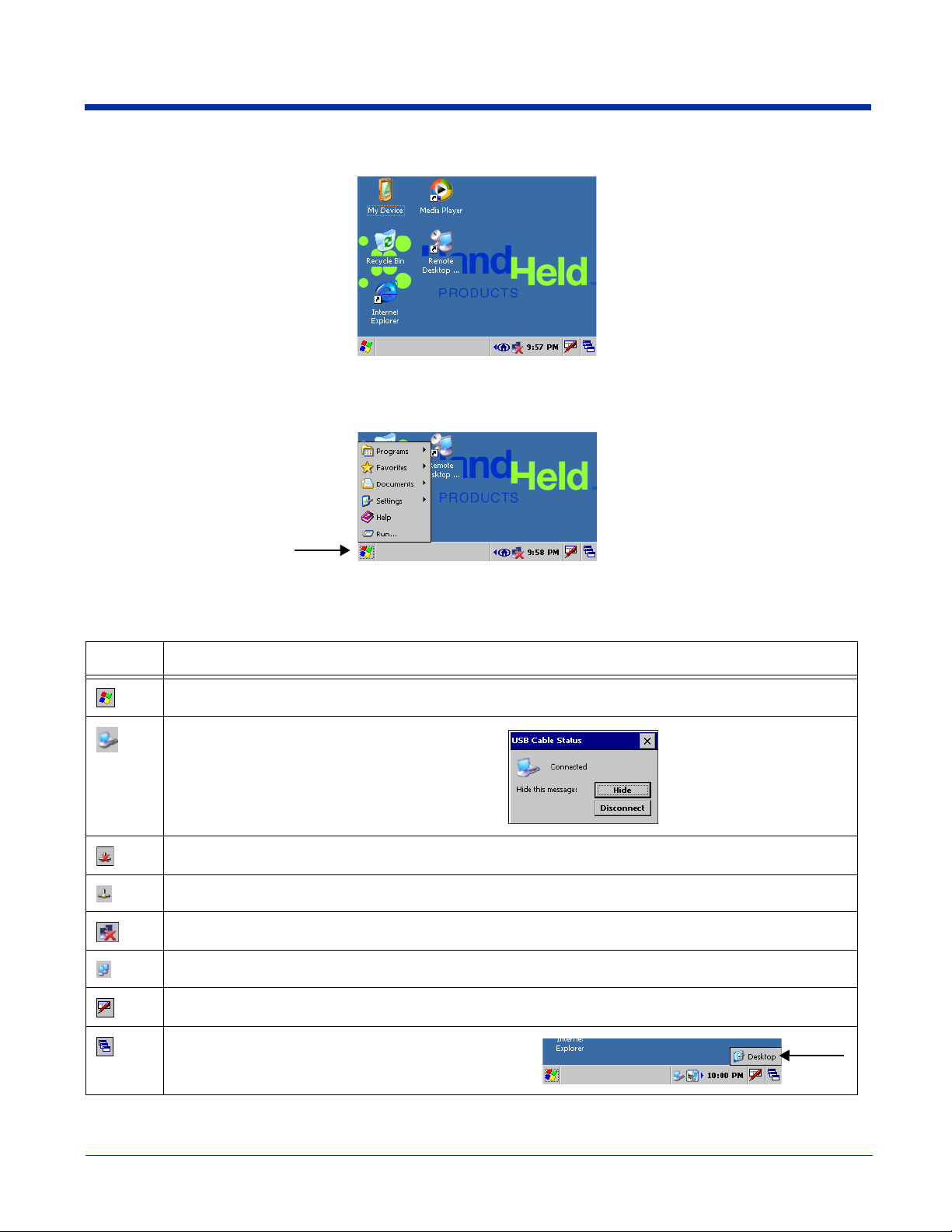
Desktop
Command Bar
The command bar is located at the bottom of every application window and provides access to the Start menu.
Task Tray Icons
Icon Description
Opens the Start menu.
The communication cable is connected. Doubletapping this icon displays the cable type and
connection status.
Wired ethernet cable is not connected.
Wired ethernet cable is connected.
802.11b radio is not connected
802.11b radio is connected.
Displays the Soft Input Panel (SIP); see page 2-3.
Tapping this button returns you to the Desktop.
The pop-up menu that appears will also show two
programs or windows currently open.
2 - 2 Rev B
3/1/07
Image Kiosk 8560/8570 User’s Guide
Page 11

Setting the Time and Date
After the device boots up, set the time and date to set the system clock to real-time.
Double-tap the time on the taskbar
OR
Tap Start > Control Panel > Date/Time.
The date and time saved here sets the system clock. Any scheduled function runs off the system clock.
Using the Soft Input Panel (SIP)
The SIP is a soft keyboard that enters text into fields and screens. The SIP pops up automatically over certain screens that
require text entry. You can also manually open the SIP when needed.
To open the SIP, tap the Input Panel icon in the task tray and select Keyboard on the pop-up menu.
On the soft keyboard that displays, tap the character keys to enter them on the screen.
To close the SIP, tap the Input Panel icon again and select Hide Input Panel.
SIP Settings
You can adjust SIP panel settings by tapping Start > Settings > Control Panel > Input Panel.
Allow applications to change the input panel state is selected by default and makes the SIP appear automatically in
applications when text needs to be typed. If you de-select this option, you must manually tap the SIP button
want to use the SIP.
Image Kiosk 8560/8570 User’s Guide Rev B
3/1/07
every time you
2 - 3
Page 12
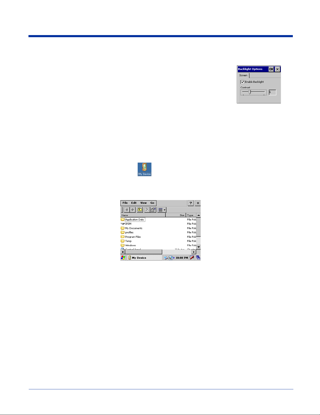
Adjusting the Backlight
Tap Start > Settings > Control Panel > Display > Backlight tab > Advanced. The Backlight
Options window opens.
The backlight is on by default (and enabled after each re-boot).
To turn off the backlight, de-select the Enable Backlight option. Because the screen goes
completely dark, the best way to enable the backlight again is to power cycle, which re-boots the
unit. While the screen is dark, the Enable Backlight option is still there but can’t be seen to be
selected accurately.
Note: We do not recommended turning off the backlight, except for test purposes.
Adjusting the Contrast
On the Backlight Options window, use the Contrast slider to adjust the contrast.
Using Windows Explorer
You can access Windows Explorer by
Double-tapping the My Device icon on the Desktop .
OR
Tapping Start > Windows Explorer.
Windows Explorer opens to the root folder level.
Use Windows Explorer to find and move files.
Selecting Text
To edit or format typed text, select it by dragging your finger across the text. Tap and hold the selection, then use the commands
on the pop-up menu to cut, copy, and paste the selected text.
Selecting Programs
To launch a program, tap Start > Programs and select a program from the list.
2 - 4 Rev B
3/1/07
Image Kiosk 8560/8570 User’s Guide
Page 13
3
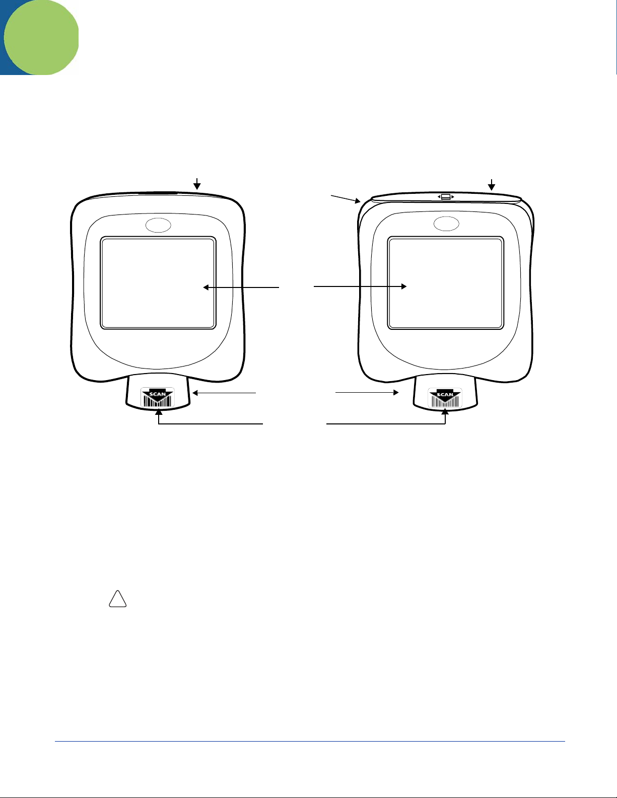
Front Panel
Hardware Overview
Reset Switch
IK8570IK8560
Reset Switch
Magnetic
Stripe
Reader
Touch
Screen
Display
Reset Switch
This switch cold boots the kiosk without having to power cycle (remove and reapply power).
For details, see Using the Reset Switch on page 3-7.
Magnetic Stripe Reader
The magnetic stripe reader is on IK8570E and IK8570EUE devices.
For more details, see Using the Magnetic Stripe Reader on page 3-8.
Touch Screen Display
The device features a 5.7" QVGA transmissive LCD color display that is backlit for maximum viewability, then
covered with an industrial touch screen protector for maximum durability. The touch screen resolution is 903 x 1238
points per inch (PPI). For touch screen input, use your finger.
Use of objects, such as paper clips, pencils, or ink pens on the touch screen can damage the input panel
and will void the warranty.
!
Screen Protectors—Hand Held Products requires screen protectors to protect the touch screen; especially when
used with applications that require high-volume interfacing with the touch screen. Screen protectors help prevent
damage to the touch screen display and are easily installed. Screen protectors can be purchased directly from Hand
Held Products (p/n 100000583). You can replace the touch screen protector;
on page 3-10.
Beeper
The internal beeper generates a tone for successful decoding.
Illumination Cone
Image Engine
see Screen Protector Replacement
Image Kiosk 8560/8570 User’s Guide Rev B
3/1/07
3 - 1
Page 14
Illumination Cone
Projecting downward from the front panel, the image engine cone houses the image engine. Slide the bar code
underneath this slot to scan a bar code or take an image.
Image Engine
The red illumination LEDs project out from the image engine at all times. For more information about imaging, see
Imaging on page 6-1.
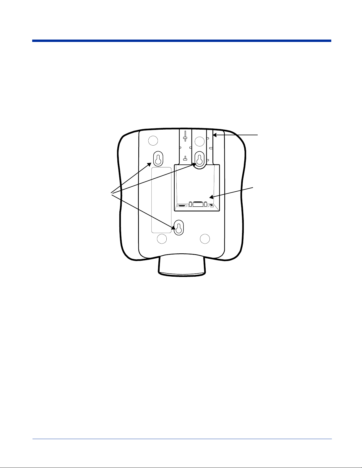
Back Panel
See Scanning a Bar Code on page 6-2.
Wire Slots
Wire Slots
Connectors
Mount Slots
Mount Slots
These two slots are designed to hold the wires of the connecting cables.
There are three connectors in a slot inside the back panel; see Connectors on page 3-3.
The back panel is designed for easy mounting, either to a wall or stand. Use these slots to mount Image Kiosks to
a flat surface or bracket. For mounting specifications,
see Mounting on page 7-1.
Connectors
3 - 2 Rev B
3/1/07
Image Kiosk 8560/8570 User’s Guide
Page 15
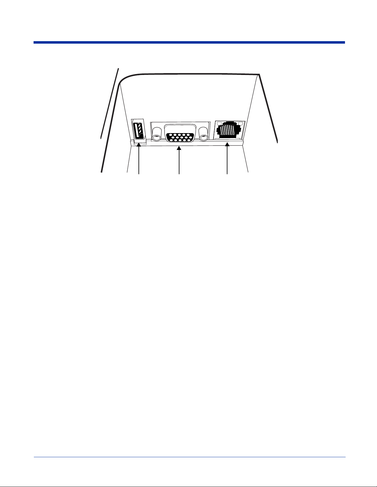
Connectors
USB Host Port
The USB Host port features a 5V DC power pass-through and can host supported USB client devices. Multiple USB
devices can be accommodated by plugging a USB HUB into the USB Host port. This is a four-pin connector and
supports USB 1.1 communication. USB 2.0 devices that are backwards compatible with USB 1.1 may be connected
to this port but will operate at USB 1.1 speeds.
For more information, see USB Host Port on page 4-10.
RJ45 JackDB15 ConnectorUSB Host Port
DB15 Connector
This is a single 15-pin, D-style, high-density female connector. All power cables have a connector that matches this
pin configuration. This connector powers the device (by receiving power from the cable) and communicates with a
host workstation using ActiveSync (USB only).
For more information, see Microsoft ActiveSync on page 4-2.
RJ45 Jack
IK8560EE, IK8570E, & IK8570EUE—A 100Base-TX/10Base-T communications port that supports wired ethernet
communication with a standard RJ45 ethernet cable. Cable must be purchased separately. You cannot power the
device through the ethernet cable. For more information,
IK8570E, & IK8570EUE on page 4-8.
IK8560CE & IK8560CEUE—The RJ45 Jack on these models is not functional. Only the IK8560EE, IK8570E, and
IK8570EUE contain the functional ethernet controller that allows for ethernet communication.
see Wired Ethernet Communication—IK8560EE,
Image Kiosk 8560/8570 User’s Guide Rev B
3/1/07
3 - 3
Page 16
Connecting the Power and Communication Cables
The Image Kiosks have standard power cables that connect to a number of communication cables to suit your environment.
Standard Power Cable
The standard power cable powers the device and with an AC power adapter to convert the voltage from the power source to the
voltage required by the device. Image Kiosks must be connected to external power to run.
Communication Cables
The Image Kiosks offer the following communication options:
• USB Cable (four feet)
• Standard RS-232 Cable (12 feet)
• RS-232 Pass-Through (Y cable)
Note: You can verify the status of the USB communication cable by the icon in the task tray; see Task Tray Icons on page 2-2.
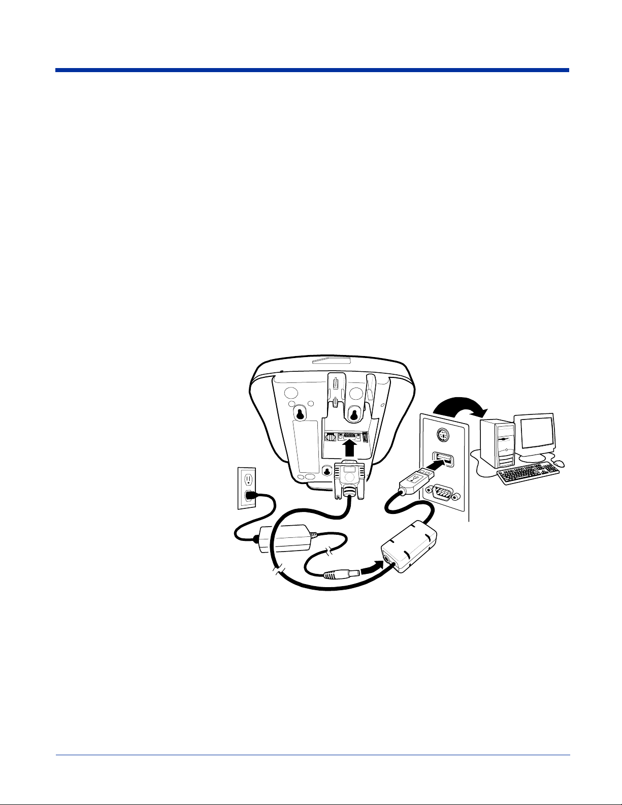
USB Cable
The USB communication cable (p/n 42206398-01E) supports USB 1.1. You can connect USB 2.0 devices that are backwards
compatible with USB 1.1 with this cable but data transfer will occur 1.1 speeds.
This cable features a single, 15-pin male connector that plugs into the DB15-pin female port on the back panel. The other end
features a standard Type A USB (1.1 or higher) connector designed to fit standard USB ports.
Note: Make sure the power switch is
turned off on the computer where
you will be installing the Image
Kiosk.
1. Plug the 15-pin connector (HDB15) of
the communication cable into the back
of the Image Kiosk.
2. Plug the USB connector into the port
on your host workstation.
3. Plug the power plug into the pod on
the communication cable.
4. Plug the AC power supply into a power
outlet.
1
4
H
os
t
2
Hardware installation is now complete.
Your Image Kiosk powers on and autoconfigures to USB.
When you power on the host workstation,
you need to complete the Found New
Hardware wizard and install the Image
Kiosk driver to configure the workstation
for ActiveSync communication;
Microsoft ActiveSync on page 4-2.
If you want to power the device without communicating, simply disconnect the USB connector from the host workstation.
see
3 - 4 Rev B
3
Image Kiosk 8560/8570 User’s Guide
3/1/07
Page 17
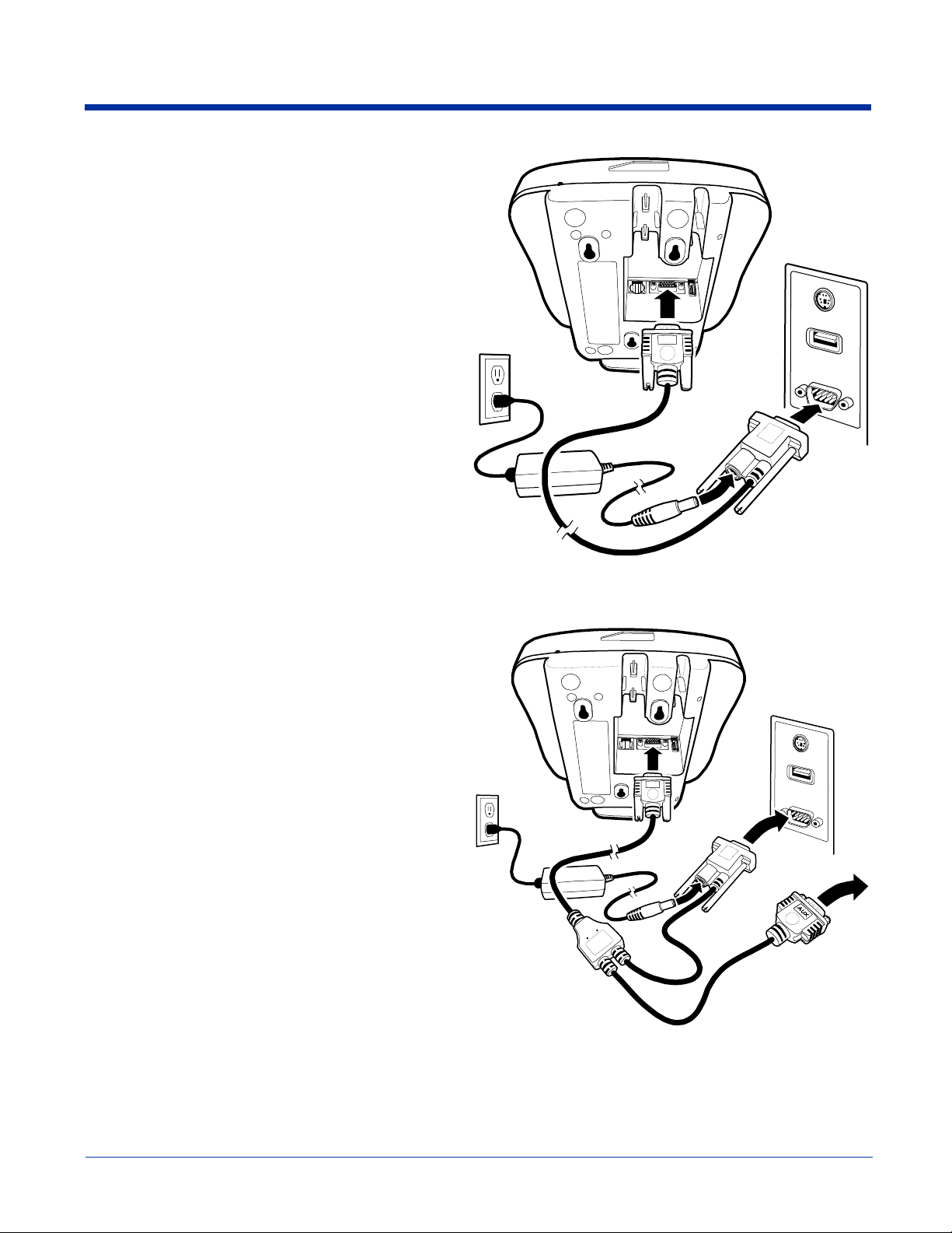
Standard RS-232 Cable
The standard RS-232 cable is 12 feet long and can connect to
multiple devices but does not support ActiveSync
communication.
Note: Make sure the power switch is turned off on the device
where you will be installing the Image Kiosk.
1. Plug the 15-pin connector (HDB15) of the serial cable into
the back panel.
2. Plug the 9-pin connector (DB9) of the serial cable into an
available serial port on the device.
3. Plug the male connector of the AC power supply cable into
the socket on the back of the DB9-pin serial cable
connector, which is plugged into the back of your host
device.
4. Plug the AC power supply into a power outlet.
Installation is now complete. Your Image Kiosk powers on and
auto-configures to RS-232. You may now turn on your host
device.
Note: If your computer has a 25-pin serial port, you will need
to obtain a 25-pin to 9-pin adapter from your local
computer store or other source.
RS-232 Pass-Through Cable
1
1
Ho
s
4
2
t
3
The RS-232 pass-through cable uses a Y cable with AC power
adapter.
Note: Make sure the power switch is turned off on the device
where you will be installing the Image Kiosk.
1. Plug the 15-pin connector (HDB15) of the serial cable into
the back panel.
2. Plug the Host DB9 connector into the other RS-232 device
(e.g., a label printer).
3. Plug the Aux DB9 connector into your host workstation
(may need a 9-pin serial female-to-female "gender
bender" to make this connect).
Note: The Aux connector is useful for upgrading the firmware
on your unit when USB is not available.
4. Plug the male connector of the AC power adapter cable
into the socket on the back of the DB9-pin serial cable
connector, which is plugged into the back of your host
device.
5. Plug the AC power supply into a power outlet.
Installation is now complete. Your Image Kiosk powers on and
auto-configures to RS-232. You may now turn on your host
device.
1
H
o
s
5
2
t
4
3
Image Kiosk 8560/8570 User’s Guide Rev B
3/1/07
3 - 5
Page 18

Power Cable
There is a six-inch L connector power-only cable you can use to power the all Image Kiosks.
This cable would be ideal for the models IK8560CE and IK8560CEUE that only have a radio.
3 - 6 Rev B
3/1/07
Image Kiosk 8560/8570 User’s Guide
Page 19
Rebooting the Device
There are three types of reboots: a warm boot, a cold boot, and a hard boot.
Warm B oot
A warm boot reboots the device without erasing data and applications stored in RAM memory.
To launch a warm boot, tap Start > Programs > Power Tools > Reboot > Warm Boot.
Cold Boot
A cold boot reboots the device, erases some data and applications stored in RAM memory, and re-installs the CAB files stored
in the Autoinstall folder.
To launch a cold boot,
•Tap Start > Programs > Power Tools > Reboot > Cold Boot.
• Use the reset switch; see Using the Reset Switch on page 3-7.
Hard Boot
A hard boot reboots the device, erases all contents of RAM memory, and re-installs the CAB files stored in the Autoinstall folder.
To launch a hard boot, power cycle the unit (remove and reapply AC power).
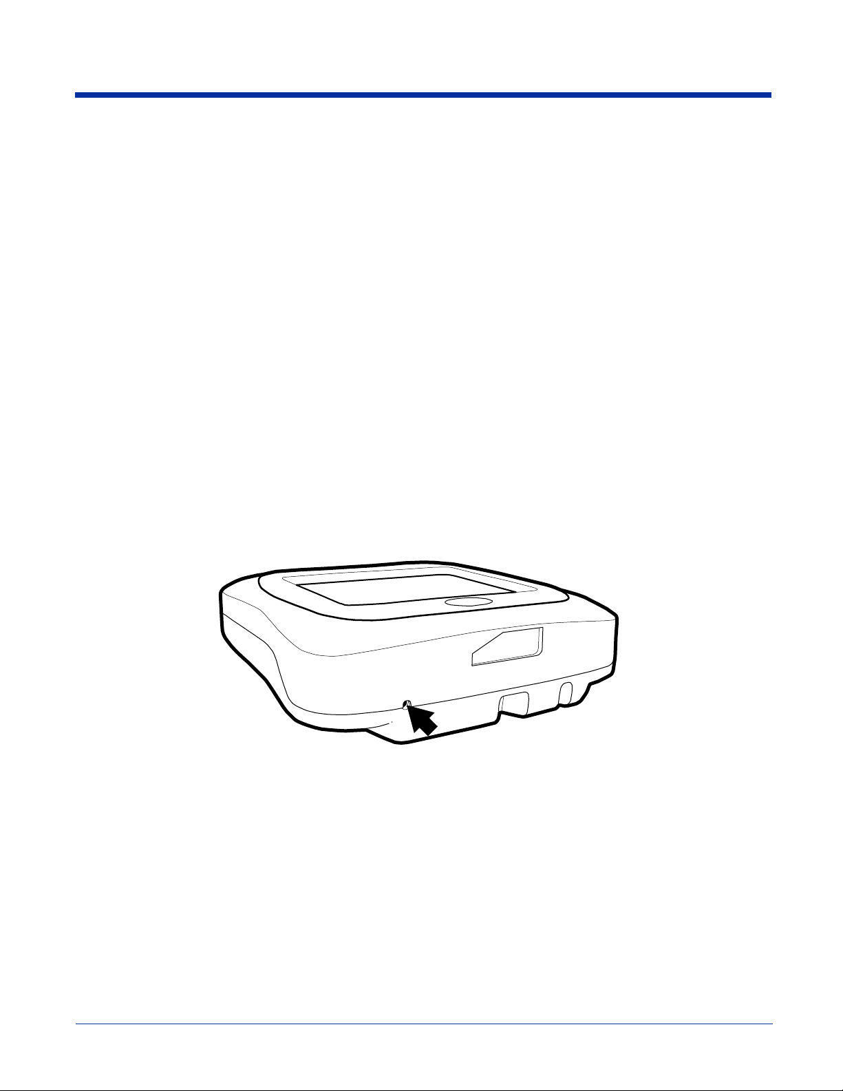
Using the Reset Switch
The reset switch appears in the same place on all Image Kiosks and allows you to cold boot the device
and reapply AC power.
Use the end of a straightened paper clip to push the reset switch on the top panel. The unit begins cold booting immediately.
without
having to remove
Image Kiosk 8560/8570 User’s Guide Rev B
3/1/07
3 - 7
Page 20

Using the Magnetic Stripe Reader
All IK8570 devices contain a magnetic stripe reader (MSR). To use the MSR, you must have an application installed on the Image
Kiosk that can read and process data from a magnetic stripe.
Fortunately, all Image Kiosks contain an MSR Demo that demonstrates some of the capabilities of the MSR.
Swiping a Card With the MSR Demo
1. Tap Start > Programs > Demos > double-tap MSR Demo .
Note: The display area should read “Ready for MSR Swipe.”
2. Make sure that the magnetic strip is facing down, towards the touch
screen display.
3. Slide the card from left to right or right to left as shown on the right.
4. MSR Demo reads the card, beeps, and displays the data according
to the options selected;
5. You can swipe the card again and the new data will display. (Scroll up to see the data from the prior swipe.)
6. You can continue to swipe cards and read the data.
To clear all prior card reads, tap File > Clear.
7. To close the MSR Demo, tap File > Exit.
see MSR Demo Options on page 3-9.
3 - 8 Rev B
3/1/07
Image Kiosk 8560/8570 User’s Guide
Page 21

MSR Demo Options
The MSR Demo main window offers many data display options.
Raw Data
When you select Raw Data from the Select Data to Display drop-down list, all the data from Tracks 1, 2, and 3 of the card display.
If you don’t want to see information from one or more of the tracks, de-select it, then swipe the card again.
Tracks 1, 2, and 3 are active only when Raw Data is selected.
Parsed Data
When you select Parsed Data from the Select Data to Display drop-down list, parsed data from the card displays.
Not all MSR cards contain parsed data. If the data on the card is not parsed, the display area reads “PARSED DATA NOT
AVAILABLE FOR THIS CARD” after you swipe the card.
Image Kiosk 8560/8570 User’s Guide Rev B
3/1/07
3 - 9
Page 22

Screen Protector Replacement
Screen protectors for Image Kiosks can be purchased at any major computer retail store or directly from Hand Held Products
(p/n 100000583).
1. To remove the old screen protector frame, insert a straightened paper clip into the small hole in the front of the Image Kiosk.
This releases the protector frame which can now be lifted off.
2. Clean any smudges or dirt from the Image Kiosk touch screen using glass cleaner or water. Wipe the surface dry.
3. Remove the protective film from the back of the new screen protector.
4. Line up the holes in the protector with the pins on the Image Kiosk screen.
3 - 10 Rev B
3/1/07
Image Kiosk 8560/8570 User’s Guide
Page 23

5. Use a tissue or soft cloth to wipe the front of the screen protector. (This makes the protector lie flat.)
6. Place the protector frame back in place and press down until it snaps shut.
Maintenance
To clean your Image Kiosk, use a soft cotton cloth lightly dampened with isopropyl alcohol. This removes any ink, fingerprint
smudges, or dirt.
Image Kiosk 8560/8570 User’s Guide Rev B
3/1/07
3 - 11
Page 24

Image Kiosk Technical Specifications
System Architecture
Processor Intel XScale PXA255 200 Mhz
Operating Platform Microsoft Windows CE 5.0
Memory IK8560 Models: 32MB Flash ROM X 64MB SDRAM of on-board memory
IK8570 Models: 64MB Flash ROM X 64MB SDRAM of on-board memory
Development Environment Image Kiosk .NET SDK for Visual Studio 2005. Setup supports C++, C#.NET, and VB.net
development
Image Kiosk SDK for eMbedded Visual C++. Setup supports C/C++ development
Third Party Software
Graphics Supported BMP, CGM, DIB, EPS, MF, PCL, PCX, PLS, JPG, and TIF
Data Inputs
Imager/Scanner 5100 Standard Range (SR) with LED aimer decodes from
Symbologies Supported See Supported Bar Code Symbologies on page 6-1.
Data Outputs
Display Window Resistive, transparent, pressure-sensitive touch screen
LCD Size 5.7 in. (14.5 cm) 1/4 VGA
LCD Active Area 4.5 x 3.3 in. (11.3 x 8.4 cm) (Active area)
LCD Resolution 320 x 240 dot, 16-bit color
Touch Pad Resolution 903 x 1238 ppi
Communications
RS-232 4800 to 115.2 Kbps
Hand Held Products MSM, ITScriptNet®, Connect
2.1 in. to 13.2 in. (5.3cm to 33.5cm) for 30 mil UPC
RS-232 Pass-Through Using Aux. Y cable with AC power adapter
PC USB AC power adapter required
USB Hub Host 5V DC power pass-through support for USB 1.1 for up to 10 devices
USB 2.0 devices that are backwards-compatible with 1.1 can be used but will operate at 1.1
speeds.
Ethernet 100Base-TX/
10Base-T
3 - 12 Rev B
IK8560EE, IK8570E, & IK8570EUE models.
Cable not supplied.
Image Kiosk 8560/8570 User’s Guide
3/1/07
Page 25

Image Kiosk Technical Specifications
WLAN IK8560CE, IK8560CEUE, IK8570E, & IK8570EUE models.
IEEE 802.11b DSSS Authentication Methodologies: Open communication, WEP (64 and
128 bit), WPA (PSK, TTLS PAP), LEAP, PEAP
Beeper Programmable
Physical
Width 7.3 in. (18.5 cm)
Depth 3.2 in. (8.1 cm)
Height 8.7 in (22.1 cm), including cone
Weight 2 lb. (.9 kg)
Operating/Storage
Temper ature
Power Requirements
Current Draw IK8560EE (non-RF): 800mA @ 12V DC
Source 120V (NA) or 230V (EU) AC adapter or powered host terminal port
Approvals and Certifications
Agency Conformance FCC Class A, CE (LVD), UL 1950, CSA 22.2
0° to 40°C (32° to 104° F)
IK8560CE & IK8560CEUE (RF): 860mA @ 12V DC
IK8570E & IK8570EUE: 870 mA @ 12 Volts DC
Image Kiosk 8560/8570 User’s Guide Rev B
3/1/07
3 - 13
Page 26

3 - 14 Rev B
3/1/07
Image Kiosk 8560/8570 User’s Guide
Page 27

4
Communication
Communication Options
There are a number of communications options.
Microsoft ActiveSync
The USB communication cable supports Microsoft ActiveSync communication. For more information, see Microsoft
ActiveSync on page 4-2.
Wired Ethernet–IK8560EE, IK8570E, & IK8570EUE
These Image Kiosks contain an ethernet port on the back panel that connects the device to an ethernet network via
standard RJ45 cable. For information,
page 4-8.
USB Host Port
The USB host port on the back panel enables you to configure the Image Kiosks as a USB host connected to other
USB devices. For more information,
802.11b Radio–IK8560CE, IK8560CEUE, IK8570E, & IK8570EUE
These Image Kiosks contain an on-board 802.11b radio that establishes the device on a wireless network.
For information, see Wireless LAN with 802.11b on page 5-1.
see Wired Ethernet Communication—IK8560EE, IK8570E, & IK8570EUE on
see USB Host Port on page 4-10.
Installing Additional Software
You can install additional programs on the Image Kiosks through most of the communication options. However, the following
requirements must be met:
• The program must be created specifically for a Windows CE 5.0 device running an Intel XScale processor.
• The program must have an EXE, CAB, or DLL extension.
• The device must have enough memory to store the program. To check memory allocation and usage, tap Start > Settings >
Control Panel > System > Memory tab
For more information,
• See Adding Programs Using ActiveSync on page 4-6.
• See Adding Programs from a Network on page 4-9.
Image Kiosk 8560/8570 User’s Guide Rev B
3/1/07
4 - 1
Page 28

Microsoft ActiveSync
Microsoft ActiveSync connects the device to a host workstation, which enables you to
• Transfer files,
• Install additional programs, and
• Synchronize information between the workstation and the device.
Requirements
Using ActiveSync with Image Kiosks requires the following:
1. A USB communication cable connecting the host workstation and the Image Kiosk; see USB Cable on page 3-4.
2. The IK8560.inf driver and wceusbsh.sys file installed in the Windows\System32 directory of the host workstation; see
Establishing the ActiveSync Connection on page 4-2.
3. ActiveSync version 4.1 or higher installed on both the host workstation and the Image Kiosk.
Image Kiosks ship with ActiveSync already installed. If ActiveSync is not already installed on the host workstation, you can
download the latest version of ActiveSync from Microsoft’s web site and run the install wizard.
Installing the Driver on the Host Workstation
You must have the IK8560.inf driver and wceusbsh.sys file installed in the Windows\System32 directory on your workstation to
establish ActiveSync communication with any Image Kiosk. You can download these files from www.handheld.com.
Also, when the Image Kiosk Power Tools and Demos is installed on a host workstation, the IK8560.inf driver and wceusbsh.sys
file are installed to the following location: C:\Program Files\Hand Held Products\Image Kiosk Power Tools and
Demos\Desktop Driver.
To establish an ActiveSync connection, you must copy and paste the IK8560.inf driver and wceusbsh.sys file to the
Windows\System32 directory on that workstation, then complete the process of Establishing the ActiveSync Connection (see
page 4-2).
For more information about Image Kiosk Power Tools and Demos, refer to the Image Kiosk Power Tools and Demos User’s
Guide, which is available for download from www.handheld.com.
Establishing the ActiveSync Connection
1. When the device is connected to the host workstation via USB cable and both the device and the host workstation are
powered on, the Found New Hardware Wizard opens on the workstation.
2. Select Install from a list or specific location (Advanced).
3. Click Next.
4 - 2 Rev B
3/1/07
Image Kiosk 8560/8570 User’s Guide
Page 29

4. Select Don’t Search. I will choose the driver to install.
5. Click Next and select Computer as the hardware type.
6. Click Next. When the wizard tells you it can’t find drivers for the device, click Have Disk.
Image Kiosk 8560/8570 User’s Guide Rev B
3/1/07
4 - 3
Page 30

7. Navigate to where the IK8560.inf file is stored on the workstation and select it. The host workstation reads the file as
“HandHeld Products IK8560.”
8. Click Next. The hardware begins installing.
9. You will see a brief flash on the Image Kiosk screen, then the ActiveSync Wizard appears on the workstation.
10. Complete the ActiveSync Setup Wizard. ActiveSync will auto-configure to USB communication.
4 - 4 Rev B
Image Kiosk 8560/8570 User’s Guide
3/1/07
Page 31

11. The Found New Hardware Wizard notifies you that setup is complete.
12. Click Finish and you are now ready to use the ActiveSync connection.
Note: You can find more information about ActiveSync in the ActiveSync Help on your workstation. In ActiveSync, click Help >
Microsoft ActiveSync Help.
Setting Up the Host Workstation
Verify that ActiveSync on the workstation has selected the appropriate communication type by clicking File > Connection
Settings.
Select for USB
Verify the communication type:
•For USB, select Allow USB connections. Do not check the serial cable box below it!
Tap OK to save changes.
Exploring the Device from the Host Workstation
Use the Explore feature of ActiveSync to transfer files between the host workstation and the device.
When the device and host workstation are connected, open the main ActiveSync window, and click Explore.
Image Kiosk 8560/8570 User’s Guide Rev B
3/1/07
4 - 5
Page 32

The Mobile Device folder opens in Windows Explorer.
The device is now treated as a mass storage device, and transferring files is as simple as dragging and dropping or copying and
pasting as you would for moving files between folders on your hard drive.
Adding Programs Using ActiveSync
When selecting programs, verify that the version of the program is designed for Windows CE 5.0 and the Intel XScale processor.
Check both by tapping Start > Settings > Control Panel > System > General tab.
!
Depending on the application, the software must be stored or installed on the host workstation.
1. Download the program to the host workstation from either a network or CD-ROM.
You may see a single EXE with the application name or a file named “setup.exe*, CAB, or DLL file. There may also be
several versions of files for different device types and processors.
2. Read any installation instructions, Readme files, or documentation that comes with the program. Many programs provide
special installation instructions.
3. *Connect the device to the workstation using a Hand Held Products communication cable.
*The program files can also be copied to a USB jump (flash) drive and then insert the jump drive into the USB host port on the
back panel. The jump drive will appear as "hard drive" under "My Device" on the unit and will allow files to run/be copied.
If the File is an Installer:
An installer program is one that installs to the workstation and the device simultaneously; one process installs to both devices.
1. On the workstation, double-click the EXE or setup.exe file. The installation wizard begins.
2. Follow the directions on the workstation screen. The installation process includes transferring the software to the device.
If the File is Not an Installer:
Some programs cannot be installed on workstations. In these cases, the appropriate files must be stored on the host workstation,
transferred to the device via ActiveSync, and installed on the device. You will know that the program cannot be installed on the
workstation if an error message appears when you try to install it stating that the program is valid but designed for a different type
of computer.
1. If you cannot find any installation instructions for the program in the Readme file or documentation, open ActiveSync and
click Explore.*
2. Copy the program file or files to the Program Files folder on the device.
If you want the program to be part of the Autoinstall that occurs after every cold boot, place the program file in the
Autoinstall folder (\\IPSM\AutoInstall).
3. Depending on the program, you may need to open File Explorer on the device, navigate to the folder where the program is
located, and tap on the program file to install it.
4 - 6 Rev B
3/1/07
Image Kiosk 8560/8570 User’s Guide
Page 33

If you copied the file to the Autoinstall folder, you can either tap on the program inside the Autoinstall folder or perform a
cold boot and the program will install as part of the Autoinstall process. Remember! A cold boot erases RAM data and
applications.
4. After installation on the device is complete, tap Start > Programs and the program appear on the menu. Tap it to open the
program.
Synchronizing
By default, ActiveSync does not automatically synchronize all types of information. Use ActiveSync Options to specify the types
of information you want to synchronize. The synchronization process makes the data (in the information types you select)
identical on both your workstation and your device.
For more information about using ActiveSync on your workstation, open ActiveSync, then open ActiveSync Help.
Image Kiosk 8560/8570 User’s Guide Rev B
3/1/07
4 - 7
Page 34

Wired Ethernet Communication—IK8560EE, IK8570E, & IK8570EUE
On these Image Kiosks, the Ethernet port on the back panel is compatible with standard 100Base-TX/10Base-T ethernet cables
with RJ45 connectors on each end.
Note: Cables must be purchased separately.
To establish an ethernet connection, simply plug one RJ45 connector into the ethernet port on the device and the other RJ45
connector into your ethernet outlet.
The Image Kiosks auto-configure the wired ethernet connection when power is applied from the power cable. DHCP is enabled
by default; a static IP must be configured manually if the network does not use DHCP.
To test the ethernet connection, tap the Internet Explorer icon on the Desktop . If the device connects to a network with
internet or an internet web server, the home page should begin loading.
To see information about IP addresses, tap Start > Settings > Network and Dial-up Connections and select the connection
type.
4 - 8 Rev B
Image Kiosk 8560/8570 User’s Guide
3/1/07
Page 35

Adding Programs from a Network
However you establish your network connection–ethernet or wireless radio–you can download and install programs from a
network.
When selecting programs, verify that the version of the program is designed for both Windows CE 5.0 and your I
processor. Check both by tapping Start > Settings > Control Panel > System > General tab.
!
1. When you have established your network connection, open Internet Explorer and navigate to the web site.
2. Download the program files to your device.
You may see a single EXE or setup.exe file, or several versions of files for different device types and processors.
If you are copying temporary files that are to be used once for the installation then discarded, then avoid copying them to the
IPSM folder since the contents of the IPSM folder are preserved over reboots.
3. Read any installation instructions, Redeem files, or documentation that comes with the program. (Many programs provide
special installation instructions.)
4. On the Desktop, double-tap the My Device icon and navigate to where you copied the program files.
5. Tap the installation file. The installation wizard begins.
6. Follow the directions on the screen to install.
ntel XScale
Image Kiosk 8560/8570 User’s Guide Rev B
3/1/07
4 - 9
Page 36

USB Communication Hardware
USB Host Port
All Image Kiosks have a 4-pin USB 1.1 host port on the back panel that supports USB communication with USB 1.1 and
backward-compatible USB 2.0 devices. All data communication occurs at USB 1.1 speeds.
Multiple USB devices can be accommodated by plugging a USB HUB into the USB Host port. Image Kiosks can support the
following USB peripherals:
• Mouse
• Keyboard
• Mass Storage
Note: The USB host port can support a maximum current output of 500mA. If all of your USB devices together require more
power, attach them to a self powered hub, and plug the hub into the Image Kiosk.
Connecting the Image Kiosks Using USB
To connect Image Kiosks to other devices via USB, simply use a standard USB cable to plug one end into the USB host port and
the other end into the USB device. Image Kiosks auto-configure to USB when power is applied.
4 - 10 Rev B
3/1/07
Image Kiosk 8560/8570 User’s Guide
Page 37

5
Wireless LAN with 802.11b
Overview
The IK8560CE, IK8560CEUE, IK8570E, and IK8570EUE have on-board 2.4 GHz 802.11b WLAN (Wireless Local Area Network)
radios that uses Direct Sequence Spread Spectrum (DSSS) technology. The signal is spread continuously over a wide frequency
band at a data rate of up to 11 Mbps. The radio is interoperable with other 802.11b Wi-Fi-compliant products including Access
Points (APs), PCs via PC card adapters and other wireless portable devices.
Configuring the 802.11b Radio
The IK8560CE, IK8560CEUE, IK8570E, and IK8570EUE contain the AEGIS Client®, a comprehensive IEEE 802.1x tool to set
up the on-board 802.11b radio. The Client is a standards-based implementation of IEEE 802.1x and can be configured to work
with almost any network equipment–wired or wireless–that supports the 802.1x authentication standard. The Client is
interoperable with 802.1x-capable wireless APs and authentication servers including Microsoft's IAS and Cisco's ACS.
The Client uses public key authentication and encryption between Wireless APs (WAP) and roaming stations to exchange
dynamic Wired Equivalent Privacy (WEP) keys. In addition, network managers can control 802.1x user profiles from a centralized
RADIUS server or, in the case of TTLS, from a RADIUS Diameter or other AAA servers. The Client supports both wireless and
ethernet interfaces.
Supported Protocols
Authentication
The Client supports the following authentication methods according to the 802.1x protocols:
• MD5
• EAP TLS
• EAP TTLS
• Cisco LEAP and PEAP
• Microsoft PEAP
Encryption
The Client supports the following encryptions methods:
• WEP (64-bit and 128-bit)
• TKIP
The Client can also configure the 802.11b without authentication or encryption; see Associating With Open APs on page 5-14.
Required Network Configuration Information
Because the Client accesses a network that is protected by the IEEE 802.1x protocol, you must configure EAP data
communication to match your network server parameters. If the EAP configuration doesn’t match your network configuration, you
can’t access the network. Therefore, make sure you have the correct network server parameters on hand when you configure
the client.
Opening the Client
Double tap the icon in the command bar.
Image Kiosk 8560/8570 User’s Guide Rev B
3/1/07
5 - 1
Page 38

Color Indicators
Note: The Client icon displays in color only when 802.11b authentication is being performed (e.g., WPA-PSK and
TKIP). No colors are shown for WEP encryption.
Icon Color Status
Green Authentication succeeded.
Yellow Authentication is in process.
Red Authentication failed.
If the icon is not yellow, red or green, then either the ports are not being controlled by 802.1x, or there is no authentication
activity on the controlled ports. The absence of yellow, red or green may also indicate that the network access server is
not an 802.1x aware device.
Blue There is no 802.11b activity. The port may not be connected to an 802.1x-aware entity.
Note: If you are setting up the 802.11b radio to run without authentication and without
encryption, this icon does not change from the standard blue;
Open APs on page 5-14.
Orange The port is associated, but there is no response to 802.11b packets.
If using WEP without 802.1x authentication, this will be the final state when the connection
is complete. If using 802.1x authentication, it is either a transient condition or can indicate
that attempts to authenticate have timed out as there was no response to 802.1x packets.
see Associating With
Gray The port is not in use or is disabled. Either the Client isn’t running, or the port is not bound
to the 802.1x protocol.
Main Window
Double-tap the icon in the command bar to open the Client . The main window opens displaying a list of ports.
Por t
Status
icon
Port Status Icon
The main window contains a port status icon to the left of each port. As the network interface starts or stops, the color of the port
icon and the status field updates to reflect the current state of the interface. The colors of the port status icon are the same as
the color of the icon in the command bar. For details about what each color means,
see Color Indicators on page 5-2.
5 - 2 Rev B
3/1/07
Image Kiosk 8560/8570 User’s Guide
Page 39

Client Menu
On the main window, tap the Client menu.
Menu Item Description
Close Closes the Client's interface, while leaving the client running.
Start/Stop Starts or stops 802.1x operation. After you finish the initial configuration, tap the network interface
and tap Start. If the port is already active, tap Stop first, then Start to force the program to read
the new configuration file.
Restart Same as a Stop followed by Start. Select this menu item when you receive a message that a
restart is necessary.
Configure Opens the client authentication windows; see Configuring Client Authentication on page 5-5.
Exit Terminates the client, which stops the 802.1x protocol.
View Menu
To access the View menu, tap View.
Menu Item Description
The Standard and Advanced Views control the number of columns displayed in the main menu.
Standard View Displays the Port (adapter name) and State columns. This is the default view.
Advanced View Displays the Port (adapter name), State, Primary Wireless Network, Wireless Network, and MAC
Address of AP columns. Scroll right to see all columns.
Event Log Displays the event log in a custom viewer. The Event Log
is a text file that contains system information; each entry
is listed sequentially with a time/date stamp and text
message.
Ta p Refresh to query the system again and update the
log file while you are reading it. If the file gets too large,
old entries are automatically deleted.
Logging parameters are set on the System Tab (see
page 5-7).
Image Kiosk 8560/8570 User’s Guide Rev B
3/1/07
5 - 3
Page 40

Port Menu
The Port menu enables you to configure the port. On the main window, tapping once on a port opens a popup menu.
Menu Item Description
Enable
Disable
Configure Opens the port configuration window; see Configuring Client Authentication on page 5-5.
Delete Selecting Delete has no effect because you cannot remove the radio driver from the device.
These commands enable or disable 802.1x operation on the port. The port should be enabled before
the protocol is started.
Enabling a port is not the same as starting it (see Start/Stop on page 5-3); however, both actions are
required for the Client to work.
Status Bar
The status bar at the bottom of the main window indicates the connection status between the network card and the AP.
Status Bar
Depending on the status of connectivity, the status bar displays one of the following:
• Not Associated
• AP : [AP's SSID] MAC : [AP's BSSID].
5 - 4 Rev B
3/1/07
Image Kiosk 8560/8570 User’s Guide
Page 41

Setup Windows
Use the following navigation aid to examine the configuration options for each set of configuration windows:
Configuring Client Authentication (see page 5-5)
• User Tab (see page 5-5)
• System Tab (see page 5-7)
• Server Tab (see page 5-8)
Configuring a Port (see page 5-9)
• Wireless Networks Tab (see page 5-9)
• Protocol Tab (see page 5-10)
Configuring a Network Profile (see page 5-11)
• Profile Info Tab (see page 5-11)
• WEP Mgmt Tab (see page 5-12)
• WPA Settings Tab (see page 5-13)
Configuring Client Authentication
Each user account needs to define the protocol and the credentials used to authenticate a user. When you start and stop on a
port, you are enabling and disabling the authentication established here.
Note: Fields will be grayed out if not relevant to the selected protocol.
On the main window, tap Client > Configure. Complete the User (see page 5-5), System (see page 5-7), and Server (see page
5-8) tabs.
The configuration windows are in portrait orientation, which means that a portion of the window is below the command bar
at the bottom. To access the rest of the window, tap and hold on a point on the right side of the window that is not active
(for example, a button or a field) and drag the window up. After you complete your tasks on the lower portion of the window,
!
you must drag the window back down so that you can tap OK to save changes. For the best results, tap and hold on the
rightmost edge of the window.
User Tab
Enter the credentials used to authenticate a user.
Field Description
Profile Multiple user credential profiles can be created for use when the user roams from one network to
another. The drop-down list contains existing authentication credential profiles. Select a profile from the
list to edit it in the fields that follow.
• Tapping Add permits new profiles to be added to the list. A window appears where you can enter a
name for the new profile.
• Enter a Profile name and tap OK. The name entered appears in the Profile drop-down list.
• Tapping Delete deletes authentication profiles. To be deleted, a profile cannot be assigned to a
configured network.
Image Kiosk 8560/8570 User’s Guide Rev B
3/1/07
5 - 5
Page 42

Field Description
Identity This is the 802.1x identity supplied to the authenticator. The identity value can be up to 63 ASCII
characters and is case-sensitive.
For tunneled authentication protocols such as TTLS and PEAP, this identity (called the Phase 1 identity)
is sent outside the protection of the encrypted tunnel. Therefore, it is recommended that this field not
contain a true identity, but instead the identity “anonymous” and any desired realm (e.g.
anonymous@myrealm.com). For TTLS and PEAP, true user credentials (Phase 2 identity) are entered
in the Tunneled authentication section.
When used with PEAP and the .NET Enterprise Server Version 5.2, this field must contain the identity
used in both Phase I and Phase II. The Phase II identity field is ignored.
Password This is the password used for MD5-Challenge or LEAP authentication. It may contain up to 63 ASCII
characters and is case-sensitive. Asterisks appear instead of characters for enhanced security.
Authentication
type
Use certificate This is the certificate to be used during authentication. A certificate is required for TLS, optional for
Tunneled authentication area
Tunneled authentication parameters are used by only by TLS, TTLS and PEAP protocols, in Phase 2 of authentication, and
after the secure tunnel has been established. The fields in this section are active only if the TLS, TTLS, or PEAP is selected
as the Authentication type.
Identity The user identity used in Phase 2 authentication. The identity specified may contain up to 63 ASCII
This is the authentication method to be used - MD5-Challenge, LEAP, PEAP, TLS, or TTLS.
Your network administrator should let you know the protocols supported by the RADIUS server. The
RADIUS server sits on the network and acts as a central credential repository for Access Servers that
receive the radio signals and ultimately block or allow users to attach to the network.
TTLS and PEAP, and unused by MD5 and LEAP. Therefore, this option becomes active only when TLS,
TTLS, or PEAP is selected as the Authentication type.
If Use certificate is enabled, the client certificate displayed in the field
is the one that is passed to the server for verification. To select a
client certificate, tap Change and select the certificate from the list
that appears.
To appear in this list, certificates must be installed in the system; see
Certificates on page 5-16.
The Issued to column should match the Identity field and the user ID
on the authentication server used by the authenticator.
Your certificate must be valid with respect to the authentication server. This generally means that the
authentication server must accept the issuer of your certificate as a Certificate Authority.
When obtaining a client certificate, do not enable strong private key protection. If you enable strong
private key protection for a certificate, you will need to enter an access password for the certificate each
time this certificate is used.
characters, is case-sensitive and takes the form of a Network Access Identifier, consisting of <name of
the user>@<user’s home realm>. The user’s home realm is optional and indicates the domain to which
the tunneled transaction is to be routed.
Because Microsoft .NET Enterprise Server Version 5.2 does not use this parameter for PEAP, This field
will have no effect for PEAP at this time. Phase 1 identity is used instead.
Password The password used for the tunneled authentication protocol specified. It may contain up to 63 ASCII
characters and is case-sensitive. Asterisks appear instead of characters for enhanced security.
Protocol This parameter specifies the authentication protocol operating within the secure tunnel.
The following protocols are currently supported for TTLS:
EAP-MD5, CHAP, PAP, MS-CHAP, MS-CHAP-V2
The following protocols are currently supported for PEAP:
EAP-MS-CHAP-V2, TLS/SmartCard, Generic Token Card (EAP-GTC)
5 - 6 Rev B
Image Kiosk 8560/8570 User’s Guide
3/1/07
Page 43

System Tab
Define logging settings and the port manger timeout period.
Field Description
Log Level These settings control the detail of the log messages generated by the Client. Each level is
cumulative. By default, all errors, warnings, and information events are logged. Each entry records a
severity code (of one [debug message] to four [error] asterisks), a time stamp, and a message.
• Errors - only the most severe conditions are logged.
• Warnings - less severe conditions are logged.
• Information - all errors, warnings, and information events are logged. This is the default setting.
• Debugging - creates a log message each time the Client detects or reacts to an event. Be advised
that log entries fill memory quickly if the Debugging level is chosen. Do not use the Debugging
option for a significant length of time because most internal operations generate messages.
For more information, see Logging on page 5-7.
Defaults button Tap this button to return log settings to the default settings.
Scan List
Timeout
Save Credentials
for (min)
Disable Wireless
Zero Config
The time interval at which the Client polls the ports. This value should not be changed from the 10second default unless technical support advises you to do so.
The amount of time the Client saves credentials.
Use this option only as directed by technical support.
Selecting this option disables other wireless utilities.
Logging
The event log is an ASCII text file named “LOG8021X.TXT” located in the directory
defined by the WINDIR environment variable (usually the Windows directory).
In the text file, the format of the entries is: Time StampMessage Text
Note: To see an event log on the window, tap View > Event Log (see page 5-3).
If you wish to start with a blank file or clear the event log, close the Client (so that the
icon no longer appears in the command bar) and delete the log file (log8021x) in
WIndows Explorer. When you restart the Client, a new log file is created.
Image Kiosk 8560/8570 User’s Guide Rev B
3/1/07
5 - 7
Page 44

Server Tab
The Server tab controls how the Client authenticates the server that handles the 802.1x protocol on the network side. This applies
only to the TLS, TTLS, and PEAP authentication methods and is used to tell the Client what server credentials to accept from
the authentication server to verify the server. The Client uses this information to verify that the Client is communicating with a
trusted server.
Field Description
Do not validate server
certificate chain
Certificate issuer
must be
Allow intermediate
certificates
Server name must be This is either the server name or the domain the server belongs to, depending on which option
Must match exactly When selected, the server name entered must match the server name found on the certificate
Must contain domain
name
If this option is selected, the server certificate received during the TLS/TTLS/PEAP message
exchange is not validated.
This is the certificate authority used during TLS/TTLS/PEAP message exchange. Any Trusted
CA is the default selection and means that any certificate authority can be used during
authentication.
Both trusted intermediate certificate authorities and root authorities whose certificates exist in
the system store are available for selection in the drop-down list.
This option is selected by default and enables unspecified certificates to be in the server
certificate chain between the server certificate and the certificate authority selected in the
Certificate issuer must be field.
When selected, this option allows the server certificate received during negotiation to be issued
directly by the certificate authority or by one of its intermediate certificate authorities.
If disabled, then the selected Certificate issuer must have directly issued the server certificate.
is selected below the text field.
During authentication, this name will be compared to the server certificate’s Subject: CN field.
exactly.
When selected, the server name field identifies a domain and the certificate must have a server
name belonging to this domain or to one of its sub-domains (e.g., zeelans.com, where the
server is blueberry.zeelans.com).
5 - 8 Rev B
3/1/07
Image Kiosk 8560/8570 User’s Guide
Page 45

Configuring a Port
On the main window, tap on a port (e.g., ) and tap Configure.
Note: When the AEGIS Client window appears, it will be too tall to fit on the display. To view the bottom half of the window,
simply tap and hold the right side of the window, then drag it up until the bottom half can be viewed.
Complete the Wireless Networks Tab (see page 5-9) and the Protocol Tab (see page 5-10).
Wireless Networks Tab
Field Description
Available Networks Displays the networks the device recognizes as available to connect to.
Move to Configured Activates after the available networks have been retrieved. Select the network you wish to
connect to, and tap Move to Configured. This selects the network and moves it to the Configured
Networks list.
Scan Displays a list of networks broadcasting their availability.
You can also attach to networks that are not broadcasting by tapping Scan.
Configured Networks Displays the configured network profiles saved in the device. The order of the network profiles in
this list is the same order (from the top down) that the device uses to connect to a network.
default This is the default network configuration that installs when the Client installs. This network profile
associates with any network and is already configured with standard settings. You can modify
this setting to match your desired connection.
If you are in a location with only one AP (or more than one AP that attaches to the same
network), the default profile may be sufficient without requiring the selection of a specific network
or networks.
If default is last in the list, it can act as a wildcard if the device is out of range of the primary
networks (listed first).
Do NOT place default at the top or middle of the list if you are connecting to other networks! If
default is any place other than last, connection to the other list entries is never attempted.
Note: There is nothing special about the name "default". You could configure any other record
similarly and it would behave the same way.
Up & Down Moves a selected network up or down one place in the list.The order of the networks in this list is
the exact order that connections will be attempted. The network listed first will be attempted first
and so on. Place your primary networks first.
Add Manually adds a network to the Configured Networks list if the AP does not broadcast its SSID or
Remove Removes a selected network from the list.
Properties Displays the properties of the network selected in the list. Tap this button to edit existing wireless
you are pre-configuring the client for an AP that is not currently in range. For details,
Configuring a Network Profile on page 5-11.
network configurations.
For details, see Configuring a Network Profile on page 5-11.
see
Image Kiosk 8560/8570 User’s Guide Rev B
3/1/07
5 - 9
Page 46

Protocol Tab
The Protocol tab configures parameters that apply to all the networks the selected port connects to.
Field Description
Protocol Settings These are the timer intervals and retry settings defined in the 802.1x standard. They determine how
long the supplicant state machine will wait in a given state. These parameters shouldn’t be modified
without an understanding of the supplicant state machine. For more information about the supplicant
state machine, obtain its 802.1x protocol specification.
The parameters are:
• Authentication Timeout—The period of time the Client remains in the authenticating or acquired
state without receiving a response from the AP or switch.
• Held Timeout—The period of time the Client remains in the held state after failing authentication.
• Start Timeout—The period of time the Client remains in the connecting state before restarting
when there is no response.
• Number of Start Attempts—The number of times the Client restarts before giving up. At that point,
the Client then defaults to the authenticated state, but there will be no network connectivity because
the protocol exchange was never completed.
Display EAP
notifications
Renew IP address Initiates a DHCP request to obtain a dynamic IP address after a successful authentication, but only if
Specifies that the EAPOL notification message will be displayed to the user. An authenticator may
use such notification to inform you, for example, about a near password expiration. However, some
authenticators send chatty and annoying notifications that may, for the convenience of the user, be
suppressed. Note that all notifications are written to the event log even if they are not displayed.
the client detects that the connected network (the SSID) has changed. The result is that renewal
should not occur upon re-authentication, but does occur at boot or when connecting to a different
network.
If you have a slow authenticator, you may wish to enable this option when configuring the service
because a slow authenticator may prevent you from getting a DHCP-assigned IP address upon bootup. This option is ignored if the given adapter has a static IP address.
5 - 10 Rev B
3/1/07
Image Kiosk 8560/8570 User’s Guide
Page 47

Configuring a Network Profile
You can configure a network based on an AP in range, create a new network, or modify the default (see page 5-9) network. Both
methods start on the Wireless Networks Tab (see page 5-9) and open the Profile Info, WEP Mgmt, and WPA Settings tabs on
which you configure the network profile and save the settings.
• Profile Info Tab on page 5-11
• WEP Mgmt Tab on page 5-12
• WPA Settings Tab on page 5-13
Note: The settings on these tab windows are interrelated. This means that selecting one may disable access to others.
To configure a network to an AP in range, double-tap one of the networks in the Configured Networks list (to make sure the AP
you want is in the Configured Networks list, select it in the Available Networks list and tap Move to Configured.) When the Profile
Info tab opens, information from the AP autofills some fields on these tabs.
To add a network that is not in the Available Networks or Configured Networks list, tap Add. When the Profile Info tab opens, it
contains the
Profile Info Tab
default (see page 5-9) settings.
Field Description
Network Profile If you are configuring a network from the list, the name that appears in this field is the same as the
name in the Configured Networks list and, by default, is the same as the broadcast SSID. This name
cannot be changed.
If you are adding a new network, this field is configurable.
Network Name This is the SSID of the AP. If the AP broadcasts its SSID, then this value is retrieved from the Available
Networks list and this field is completed automatically. If the SSID does not broadcast, then the field will
be active and you must manually enter the value here.
Peer-to-Peer
Group
Do active scan Select this option whenever the AP (or client, for ad hoc mode) is not broadcasting its SSID.
Authentication
Profile
Select this option to have two or more client workstations communicate with each other without the
benefit of an AP, otherwise known as ad hoc mode.
You should also select Do Active Scan and, on the WEP Mgmt tab, select Use key for data
encryption while entering a common key for both sides. WPA is not supported in this mode.
Note: This option is not available when Associate with any available network is selected.
Select the authentication profile associated with this network and tap View. The drop-down list contains
client profile names created in the User tab of the client configuration area;
default is the default authentication profile.
see User Tab on page 5-5.
Image Kiosk 8560/8570 User’s Guide Rev B
3/1/07
5 - 11
Page 48

WEP Mgmt Tab
Enter the appropriate WEP parameters for the network.
Field Description
Provide encryption
key dynamically
Use key for data
encryption
Use key to
authenticate with AP
Key In this field, enter the WEP key to use for data encryption or authentication to the AP.
Key Index/Transmit
Key
This option is selected by default. The other WEP settings on this page are disabled to enable
dynamic encryption. Selecting this option also enables WPA; the WPA Settings tab appears.
To enter a custom WEP, de-select this option. The other fields become active and the WPA
Settings tab no longer appears.
Select this option to manually enter a WEP key (in the Key field) to encrypt your data to the AP.
Selecting this option toggles the WEP authentication mode between Open and Shared. When
selected, the WEP key (entered in the Key field) is used when clients authenticate with the AP
via a challenge/response mechanism (Shared). When not selected, the only authentication
performed is to check that a client's SSID setting matches the SSID of the AP (Open).
ASCII: 5 or 13 characters
Hexadecimal: 10 or 26 characters.
When the key entered is in the correct format, the window changes to display the type–ASCII or
Hexadecimal.
This list contains the available keys. You may enter up to four keys for reception; the Client will
try all four to find one that works with the AP.
Select the key to be used for transmission as well. If the key selected is the transmit key, the
Transmit key box is checked.
To change the transmit key, select another key and check the Transmit key box. The check box
of the original transmit key will be automatically de-selected.
5 - 12 Rev B
3/1/07
Image Kiosk 8560/8570 User’s Guide
Page 49

WPA Settings Tab
This tab controls the WPA settings. This tab window is available only if Provide encryption key dynamically is selected on the
WEP Mgmt tab is selected.
Field Description
WPA Mode This drop-down list contains the following options:
• Disabled: Do not enable WPA mode. This is the default selection.
• WPA 802.1x: Enable WPA and obtain key information through the 802.1x protocol.
• WPA PSK: Enable WPA with Pre-Shared Key (PSK) information entered in the field below.
This mode is used if the 802.1x protocol is not being used for authentication.
Encryption Select the desired encryption.
• WEP: The least secure of the encryption methods. WEP uses a single encryption key of either
40 or 104 bits. WPA uses a 256 bit Pre-shared key.
• TKIP: Uses the standard WEP format, but changes the key with every frame for improved
security and includes a message integrity capability for determining unauthorized packet
insertion.
Note: The current Image Kiosk hardware does not support AES.
PSK pass-phrase This field activates if you select WPA PSK as the mode.
This field accepts only hexadecimal keys that are 8 to 64 characters long.
Image Kiosk 8560/8570 User’s Guide Rev B
3/1/07
5 - 13
Page 50

WEP Encryption Without Authentication
1. On the Main Window (see page 5-2), tap the port and select Configure on the popup menu.
2. On the Wireless Networks Tab (see page 5-9), select the SSID and tap Properties.
3. On the Profile Info Tab (see page 5-11), select Do active scan.
4. On the WEP Mgmt Tab (see page 5-12), select Use key for data encryption.
5. Enter the WEP Key; see Key on page 5-12. Tap OK.
6. On the main window, tap Client > Restart to restart the Client.
7. Wait as the Client connects.
8. When the connection is complete, the Port Status Icon (see page 5-2) on the main window reads Associated instead of
Authenticated. However, the log file (see Logging on page 5-7) will read “Entered AUTHENTICATED state” when recording
this event.
Associating With Open APs
To associate with open APs means to set up the 802.11b radio without authentication or encryption.
1. Double-tap the Client icon on the command bar .
2. On the Main Window (see page 5-2), tap on the port and select Configure on the popup menu.
3. On the Wireless Networks Tab (see page 5-9), tap Add in the Configured Networks section.
4. On the Profile Info Tab (see page 5-11), enter your AP's SSID in the Network Profile field.
5. Select default in the Authentication profile drop-down list.
6. On the WEP Mgmt Tab (see page 5-12), make sure none of the options are selected. Tap OK,
7. Tap OK on the Wireless Networks tab.
8. On the Main Window (see page 5-2), tap Client > Restart to restart the client.
9. Wait as the Client connects.
10. When connection is complete, the Port Status Icon (see page 5-2) turns yellow and the Status Bar (see page 5-4) reads
“Associated”.
Note: If your AP is strictly an AP and not a DHCP server, then you must statically assign an IP address and subnet mask.
5 - 14 Rev B
3/1/07
Image Kiosk 8560/8570 User’s Guide
Page 51

Saving Radio Settings
The radio settings in the Client update the registry. Those settings will be erased during each cold boot (or power cycle) unless
you save a REG file containing the Client’s radio settings in the \IPSM\Autoinstall folder of the device.
Using the Registry
Each device contains a RegEdit Power Tool that can export specific registry entries into a single REG file that contains only the
selected registry keys. Use RegEdit to create a REG file that contains the 802.11b radio settings and save the REG file to the
\IPSM\Autoinstall folder. Then, the REG file will be installed and the radio settings applied when the device boots up.
Do NOT place two REG files that contain overlapping registry data into \IPSM\AutoInstall at the same time.
!
Saving Radio Settings on One Device
1. Configure the radio and save settings in the Client.
2. Verify that the radio works that way you want it to.
3. Perform a warm boot; tap Start > Power Tools > Reboot > Warm Boot. Wait as the device boots up.
4. When the Desktop appears, tap Start > Programs > Power Tools > RegEdit .
5. Navigate to the key \HKEY_CURRENT_USER\Software\MDC\802.1x.
6. Leave the key highlighted and tap File > Export.
7. Save the REG file with a name of your choice to the \IPSM\AutoInstall folder. (Use the SIP to enter the name.)
8. Tap OK. This REG file will load during the next cold boot.
Saving Radio Settings on Multiple Devices
After you have configured the radio on one device and exported those settings into a REG file—see Saving Radio Settings on
One Device on page 5-15—copy that REG file and paste a copy of it on your hard drive. Then, save that same REG file to the
\IPSM\Autoinstall folder of the devices that you want to have the same radio configuration.
During each hard reset, Autoinstall calls that REG file, which loads the radio settings and configures the Client.
Image Kiosk 8560/8570 User’s Guide Rev B
3/1/07
5 - 15
Page 52

Certificates
During configuration, you may have specified one or two certificates to use during the authentication process.
Certificate Requirements
The specified identity should match the Issued to field in the certificate and should be registered on the authentication server
(i.e., a RADIUS server) that is used by the authenticator. In addition, your certificate must be valid on the authentication server.
This requirement depends on the authentication server and generally means that the authentication server must know the issuer
of your certificate as a trusted Certificate Authority (CA).
If the selected certificate does require a password or pass phrase to decode the private key, enter this value in the Certificate
Pass Phrase field. This value will be encrypted when the configuration is saved. However, on some systems, there may not be
a certificate.
Note: Client or CA certificates can be imported from *.cer (same as *.der), *.p7b, or *.pfx files.
Installing Certificates with the Meetinghouse Certificate Installer
1. Download the certificate file to the device.
The location isn’t critical, but you may want to create a standard folder for consistency.
2. Go to Start > Programs > Meetinghouse Certificate Installer.
3. Navigate to the certificate location.
4. Tap and hold on a certificate in the list. A pop-up appears asking if you want to install the certificate.
5. Tap OK. The certificate is loaded into the correct certificate store.
Installing a Root Certificate
1. Save the certificate to the device. If no error appears when you save the certificate, it was most likely saved to the device.
Note: To make sure that the certificate persists through cold boots, install the certificate to the \IPSM folder.
2. To verify that the certificate is recognized by the operating system, tap Start > Settings > Control Panel > Certificates
. This opens the Certificates window, which displays all the certificates on the device.
3. Scroll through this list until you see the certificate you installed.
4. After you have identified your certificate in the list, tap OK to close.
5. To use the certificate in a network profile, double-tap the Client icon in the command bar .
5 - 16 Rev B
3/1/07
Image Kiosk 8560/8570 User’s Guide
Page 53

6. Tap on the radio port on the main window and select Configure on the popup menu.
7. Tap the Server tab and select the certificate from the Certificate issuer must be drop-down list.
8. Tap OK to save the setting and close the port configuration.
Image Kiosk 8560/8570 User’s Guide Rev B
3/1/07
5 - 17
Page 54

Advice and Workarounds
Issue Possible Causes and Solutions
The Client will not start on the device with an
error message about missing files.
The wireless network interface (port) does not
appear in the main AEGIS window.
The Client is not attaching to the correct AP. The default network profile instructs the client to attach to the first
The Client is failing authentication even though
all my information was entered correctly.
My AP does not broadcast its SSID. Even
though I have manually configured an AP with
that name, the Client won't associate with it.
I am authenticated, but I don't get an IP
address through DHCP.
I cannot attach to my old network that does not
support 802.1x authentication, but is using
WEP encryption.
I made changes, but they do not appear to have
taken effect.
How do I enable peer-to-peer (ad-hoc) mode to
have two clients communicate without an AP?
Perform a hard reset.
• The license is not valid.
• Restart the client: on the main window tap Client > Restart.
• Perform a hard reset.
• If problem continues to persist through all of the above, there may be
a hardware failure.
available AP. You must select a network, move it to the Configured
Networks list, and then move it above default in the list using the up
arrow buttons.
For more information, see Wireless Networks Tab on page 5-9.
1. Verify that the network profile for the AP corresponds to the
authentication profile you created for it:
• Select the network profile in the Configured Networks list.
• Tap Properties. The Profile Info tab opens - see page 5-11.
• In the Authentication profiles drop-down list, select the profile
you want to review.
• Tap View. The User tab appears displaying the profile’s
information.
2. Verify that you have configured the identity and password into the
correct fields on the User tab (
profile. If you are using PEAP or TTLS, the username and password
are entered in the Tunneled authentication section.
• Make sure that the Network Name field contains the AP’s SSID.
• Verify that Do Active Scan is selected on the Profile Info tab; see Do
active scan on page 5-11. Otherwise, the Client will not attempt to find
the AP.
• On the main window, tap on the port, tap Configure on the popup
menu, and select the Protocol tab. Verify that Renew IP Address is
selected;
• Make sure that radio is configured for DHCP and not assigned a static
IP address.
•On the Wireless Networks Tab (see page 5-9), verify that the desired
SSID is at the top of the Configured Networks list so that it’s accessed
first.
• See WEP Encryption Without Authentication on page 5-14.
Always tap OK before exiting a window you have changed.
Then, on the main window, tap Client > Restart to restart the Client.
• On the Wireless Networks window, move a network to the Configured
Network list.
• On the Profile Info tab, give each side the same network name (SSID).
•Select Peer-to-Peer Group (ad hoc mode) and Do active scan.
• On the WEP management section, select Use key for data
encryption and enter an identical key for both clients.
• Verify that this network profile is the first (or only) one in the
Configured Network list and try to restart both clients at roughly the
same time.
see page 5-10.
page 5-11) in the authentication
5 - 18 Rev B
3/1/07
Image Kiosk 8560/8570 User’s Guide
Page 55

6
Imaging
Overview
Image Kiosks use Adaptus Imaging Technology™ with an integrated Hand Held Products 5100 Standard Range (5100SR) image
engine. When the Image Kiosk is powered the external illumination LEDs are always enabled providing the required illumination
for the 5100SR image engine; however the engine may only be enabled for scanning under software application control. Please
refer to the Image Kiosk SDK online help for details on connecting to and using the integrated scan engine.
The included Scan Demo (see page 6-4) enables the image engine for use in the Scan Demo only.
Supported Bar Code Symbologies
The 5100SR image engine supports the following bar code symbologies:
• Australian Post
•Aztec Code
• Aztec Mesas
• British Post
• Canadian Post
• Codabar
• Codablock F
• Code 11
• Code 39
• Code 49
• Code 93 and 93i
• Code 128
• Data Matrix
•EAN-8
•EAN-13
• EAN•UCC Composite
• Interleaved 2 of 5
• ISBT 128
• Japanese Post
• KIX (Netherlands) Post
• MaxiCode
•MicroPDF417
•MSI
•OCR
• PDF417
• Planet Code
•Plessey Code
•Postnet
• QR Code
• Reduced Space Symbology (RSS-14, RSS Limited, RSS Expanded)
• Straight 2 of 5 IATA
• TCIF Linked Code 39 (TLC39)
•UPC-A
•UPC-E
•UPC-E1
Default Bar Code Symbologies
Image Kiosks defaults to the following linear bar code symbologies:
•UPC-A
•UPC-E
•EAN/JAN
• Code 128
• Interleaved 2 of 5
• Code 39
• Codabar
•MSI
•PDF417
• Plessey Code
•RSS-14
Image Kiosk 8560/8570 User’s Guide Rev B
3/1/07
6 - 1
Page 56

Scanning a Bar Code
If you are running a software application, such as the Scan Demo, that accepts bar code information, simply slide a bar code
underneath the illumination cone. A beep sounds on successful decoding.
Illumination Cone
Omni-Directional Aiming
Image Kiosks supports omni-directional aiming in two of the three optimal imaging modes
Omni-directional aiming means the bar codes label can be read if placed under the illumination cone in any orientation.
6 - 2 Rev B
3/1/07
Image Kiosk 8560/8570 User’s Guide
Page 57

Sample Bar Codes
The following are bar code samples you can use with the Scan Demo to verify decoding:
Sample Code 128 Sample Codabar
Readout: “Code 128” Readout: “13579”
Depth of Focus (DOF) Specifications
The point of reference for the DOF specifications is from the outermost edge of the illumination cone. Ambient light level at 535
Lux. Depth is measured in inches.
Code Near Far
MaxiCode
(35-mil)
Data Matrix
15-mil (ECC 200)
PDF417, ECL4
10-mil
PDF417, ECL4
8-mil
PDF417, ECL4
6.6-mil
Code 39
15-mil
Code 39
10-mil
Code 39
8-mil
UPC-A
13-mil, 100%
Postnet 1.2” 3.1”
12-point
OCR-A
Contact 10.2”
0.9" 3.7"
0.3" 6.2"
0.5” 5.2”
1.7" 3.4"
Contact 10.0”
0.4” 6.4”
0.7” 4.8”
Contact 9.7”
Contact 9.0”
12-point
OCR-B
Contact 8.2”
Image Kiosk 8560/8570 User’s Guide Rev B
3/1/07
6 - 3
Page 58

Scan Demo
Image Kiosks ship with a sample application called Scan Demo that can be used to demonstrate the scanning capabilities of the
device. To launch and use the Scan Demo application please follow the following steps:
1. Tap Start > Programs > Demos and double-tap the Scan Demo icon . The Scan Demo window opens and the image
engine is activated.
2. Slide a bar code under the illumination cone and tap Scan.
Illumination Cone
3. The device beeps and the bar code data appears on the screen.
Scanning Options
You can always manually scan the bar code inserted under the illumination cone by tapping the Scan button. The Scan menu
offers you two additional scan options: Automatic and Continuous.
Automatic Scan
Automatic scan activates the image engine at regular one second intervals. To set the device to automatic scan,
tap Scan > Automatic and the engine begins scanning at one-second intervals. Simply slide a bar code under the
illumination cone and wait for the readout to appear on the screen.
1 second is the default interval; however, you can customize the interval time by tapping Setup > Auto Scan Delay.
6 - 4 Rev B
3/1/07
Image Kiosk 8560/8570 User’s Guide
Page 59

Select an interval from 1 to 5 seconds. A checkmark appears next to the selected interval. Selecting None causes
the engine to scan continuously. To turn off automatic scanning, tap Scan > Automatic again.
Continuous Scan
Continuous scan activates the image engine continually, without a pause. To set the device to continuous scan, tap
Scan > Continuous and the engine begins scanning. Automatic scan must be turned off before you can activate
continuous scan. To turn off continuous scanning, tap Scan > Continuous again.
Note: If you want to track bar code scans during automatic or continuous scan, enable the scan statistics.
Enabling Scan Statistics
The Scan Demo can record scan statistics for each bar code scanned and for all bar codes scanned in an activated scan session.
By default, these statistics do not display on the screen.
To enable scan statistics and activate a scan session, tap Setup > View Statistics. The Scan Demo begins recording scan
statistics beginning with the next bar code scanned. The scan statistics will appear underneath the bar code readout.
Field Description
Symbology The symbology type.
Length The length of the bar code.
Count The number of scans completed since scan statistics were enabled. If you complete one scan, this
field displays a count of 1 and increases with each additional scan performed.
Time The number of milliseconds (ms) to decode the bar code.
Note: The following three fields display the cumulative scan statistics from the time that View Statistics was enabled. To
reset any of these values to zero, disable the scan statistics.
Average Time The average decode time of all bar codes decoded.
Min Time The shortest decode time of all bar codes decoded.
Max Time The longest decode time of all bar codes decoded.
Beeper
By default, the beeper sounds after each successful decoding. To turn off the speaker, tap Setup > Sound. The beeper will not
sound after your next successful scan.
Decode Mode
By default, the Scan Demo decodes in Full Omni Standard mode.
Image Kiosk 8560/8570 User’s Guide Rev B
3/1/07
6 - 5
Page 60

To chose another mode, tap Setup > Decode Mode. A checkmark appears next to the selected mode.
There are three options:
1. Full Omni/Standard This is the default scan mode. The image engine looks for any bar code within range.
2. Quick Omni The image engine attempts to decode any enabled barcode while searching a reduced area of the
3. Aggressive Linear Decoding
Symbologies
The Scan Demo can decode a bar code only if its bar code symbology is selected in the symbologies list.
To see this list, tap Setup > Symbologies.
image. By searching for a barcode in a reduced area, based around the center of the image, scanning
performance may be improved if the barcode label is found close to the center in the captured image
used by the scan engine.
The image engine attempts to decode only enabled 1D linear barcodes.
The symbologies with a checkmark are the symbologies currently selected. The Scan Demo defaults to the Default Bar Code
Symbologies on page 6-1.
Enabling and Disabling Symbologies
To enable a symbology, select it in the list. To disable a symbology, de-select it in the list. You can select and de-select more
than one symbology at a time. When you are done enabling and disabling, tap Close and then Yes on the confirmation dialog.
In addition to individual, manual selection, the Scan Demo offers you three selection options:
All Selects all the symbologies in the list.
None De-selects all the symbologies in the list; this button de-selects even the default symbologies.
Default Selects only the default symbologies; see Default Bar Code Symbologies on page 6-1.
Tap Close and save your selections. Tap Yes and you are returned to the Scan Demo window. Verify symbology selections by
scanning bar codes in the selected symbology(ies) format.
Use this button to return the Scan Demo to the default symbologies after modifications.
Note: Symbology selections apply only to the Scan Demo, not the image engine in general.
Centering
Centering is a scanning feature that requires the barcode label to be located within a specific area of the imagers field of view in
order for the label to be successful decoded. This feature allows the image engine to discriminate between symbols that are
located physically close to each other so only one symbol is captured during a decode attempt. Please refer to the Image Kiosk
SDK’s online help for further details on the use of the centering feature.
To enable decode centering, tap Options > Centering. Centering will be applied to your next scan.
6 - 6 Rev B
3/1/07
Image Kiosk 8560/8570 User’s Guide
Page 61

Enabling the Aimer
The 5100SR/SF engine contains a green aiming beam that is enabled by default in the Scan Demo. To enable the aiming beam,
tap Setup > Enable Aimer. A checkmark appears on the menu to indicate that the aiming beam is enabled.
To see the aiming beam, see Omni-Directional Aiming on page 6-2.
Auto-Send
Auto-send allows you to send decoded information over a TCP/IP connection–both wired and wireless–to a workstation.
1. Enter the TCP/IP parameters by tapping Setup > Radio Frequency.
2. Use the SIP to enter the IP Address of the receiving workstation.
3. Verify that the default TCP Port of 6000 is correct.
4. Tap Close to save.
5. Tap Setup > Auto-Send. The next bar code you decode will be sent over the TCP/IP connection.
Image Kiosk 8560/8570 User’s Guide Rev B
3/1/07
6 - 7
Page 62

6 - 8 Rev B
3/1/07
Image Kiosk 8560/8570 User’s Guide
Page 63

7
(
)
Mounting
Overview
All Image Kiosks are designed for easy mounting to a stable vertical surface. The back panel contains screw slots spaced to fit
standard mounting brackets.
Depending on your environment, you can use a mounting bracket or simply fasten screws directly to the vertical surface and
hang the Image Kiosk on the screws. Make sure to use screws appropriate to the material of the vertical surface, such as wood
or drywall.
Back Panel Mounting Dimensions
Use the following dimensions to mount your Image Kiosks.
7.29 in.
(185.1 mm.)
2.36 in.
(59.9 mm.)
1.48 in.
(37.6 mm.)
3.96 in.
(100.6 mm.)
.54 in.
(13.7 mm.)
3.49 in.
88.6 mm.
1.18 in.
(30.0 mm.)
.32 in.
(8.1 mm.)
.152 in.
(3.86 mm.)
7.56 in.
(192 mm.)
Image Kiosk 8560/8570 User’s Guide Rev B
3/1/07
7 - 1
Page 64

Connector Slots
Wire Slots
Connectors
If you want the Image Kiosk to lay flat against the mounting surface, make sure that the wires from the connectors are secured
in the wire slots.
Side Panel Dimensions
The following graphic shows the depth of Image Kiosks at its widest point.
3.16 in.
(80.26 mm.)
7 - 2 Rev B
3/1/07
Image Kiosk 8560/8570 User’s Guide
Page 65

8
Customer Support
Product Service and Repair
Hand Held Products provides service for all its products through service centers throughout the world. To obtain warranty or nonwarranty service, return the unit to Hand Held Products (postage paid) with a copy of the dated purchase record attached.
Contact the appropriate location below to obtain a Return Material Authorization number (RMA #) before returning the product.
North America
Telephone: (800) 782-4263, option 3
Fax: (704) 566-6015
E-mail: naservice@handheld.com
Latin America
Telephone: (704) 998-3998, option 8, option 4
Telephone: (800) 782-4263, option 8, option 3
Fax: (239) 263-9689
E-mail: laservice@handheld.com
Brazil
Telephone: +55 (21) 2178-0500
Fax: +55 (21) 2178-0505
E-mail: brservice@handheld.com
Mexico
Telephone: +52 (55) 5203-2100
Fax: +52 (55) 5531-3672
E-mail: mxservice@handheld.com
Europe, Middle East, and Africa
Telephone: +31 (0) 40 2901 633
Fax: +31 (0) 40 2901 631
E-mail: euservice@handheld.com
Asia Pacific
Telephone: +852-2511-3050
Fax: +852-2511-3557
E-mail: apservice@handheld.com
Japan
Telephone: +813-5770-6312
Fax: +813-5770-6313
E-mail: apservice@handheld.com
Online Product Service and Repair Assistance
You can also access product service and repair assistance online at www.handheld.com.
Image Kiosk 8560/8570 User’s Guide Rev B
3/1/07
8 - 1
Page 66

Technical Assistance
If you need assistance installing or troubleshooting, please call your Distributor or the nearest Hand Held Products technical
support office:
North America/Canada
Telephone: (800) 782-4263, option 4 (8 a.m. to 6 p.m. EST)
Fax number: (315) 685-4960
E-mail: natechsupport@handheld.com
Latin America
Telephone: (704) 998-3998, option 8, option 3
Telephone: (800) 782-4263, option 8, option 3
E-mail: latechsupport@handheld.com
Brazil
Telephone: +55 (21) 2178-0500
Fax: +55 (21) 2178-0505
E-mail: brsuporte@handheld.com
Mexico
Telephone: (704) 998-3998, option 8, option 3
E-mail: latechsupport@handheld.com
Europe, Middle East, and Africa
Telephone: +31 (0) 40 7999 393
Fax: +31 (0) 40 2425 672
E-mail: eurosupport@handheld.com
Asia Pacific
Telephone - Hong Kong +852-3188-3485 or 2511-3050
Telephone - China: +86 21 6361 3818
E-mail: aptechsupport@handheld.com
Japan
Telephone: +813 5770-6312
E-mail: aptechsupport@handheld.com
Malaysia
Telephone: +603-6201-7020
E-mail: aptechsupport@handheld.com
Online Technical Assistance
You can also access technical assistance online at www.handheld.com.
8 - 2 Rev B
3/1/07
Image Kiosk 8560/8570 User’s Guide
Page 67

Limited Warranty
Hand Held Products, Inc. ("Hand Held Products") warrants its products to be free from defects in materials and workmanship and
to conform to Hand Held Products’ published specifications applicable to the products purchased at the time of shipment. This
warranty does not cover any Hand Held Products product which is (i) improperly installed or used; (ii) damaged by accident or
negligence, including failure to follow the proper maintenance, service, and cleaning schedule; or (iii) damaged as a result of (A)
modification or alteration by the purchaser or other party, (B) excessive voltage or current supplied to or drawn from the interface
connections, (C) static electricity or electro-static discharge, (D) operation under conditions beyond the specified operating
parameters, or (E) repair or service of the product by anyone other than Hand Held Products or its authorized representatives.
This warranty shall extend from the time of shipment for the duration published by Hand Held Products for the product at the time
of purchase ("Warranty Period"). Any defective product must be returned (at purchaser’s expense) during the Warranty Period
to Hand Held Products’ factory or authorized service center for inspection. No product will be accepted by Hand Held Products
without a Return Materials Authorization, which may be obtained by contacting Hand Held Products. In the event that the product
is returned to Hand Held Products or its authorized service center within the Warranty Period and Hand Held Products determines
to its satisfaction that the product is defective due to defects in materials or workmanship, Hand Held Products, at its sole option,
will either repair or replace the product without charge, except for return shipping to Hand Held Products.
EXCEPT AS MAY BE OTHERWISE PROVIDED BY APPLICABLE LAW, THE FOREGOING WARRANTY IS IN LIEU OF ALL
OTHER COVENANTS OR WARRANTIES, EITHER EXPRESSED OR IMPLIED, ORAL OR WRITTEN, INCLUDING, WITHOUT
LIMITATION, ANY IMPLIED WARRANTIES OF MERCHANTABILITY OR FITNESS FOR A PARTICULAR PURPOSE.
HAND HELD PRODUCTS’ RESPONSIBILITY AND PURCHASER’S EXCLUSIVE REMEDY UNDER THIS WARRANTY IS
LIMITED TO THE REPAIR OR REPLACEMENT OF THE DEFECTIVE PRODUCT. IN NO EVENT SHALL HAND HELD
PRODUCTS BE LIABLE FOR INDIRECT, INCIDENTAL, OR CONSEQUENTIAL DAMAGES, AND, IN NO EVENT, SHALL ANY
LIABILITY OF HAND HELD PRODUCTS ARISING IN CONNECTION WITH ANY PRODUCT SOLD HEREUNDER (WHETHER
SUCH LIABILITY ARISES FROM A CLAIM BASED ON CONTRACT, WARRANTY, TORT, OR OTHERWISE) EXCEED THE
ACTUAL AMOUNT PAID TO HAND HELD PRODUCTS FOR THE PRODUCT. THESE LIMITATIONS ON LIABILITY SHALL
REMAIN IN FULL FORCE AND EFFECT EVEN WHEN HAND HELD PRODUCTS MAY HAVE BEEN ADVISED OF THE
POSSIBILITY OF SUCH INJURIES, LOSSES, OR DAMAGES. SOME STATES, PROVINCES, OR COUNTRIES DO NOT
ALLOW THE EXCLUSION OR LIMITATIONS OF INCIDENTAL OR CONSEQUENTIAL DAMAGES, SO THE ABOVE
LIMITATION OR EXCLUSION MAY NOT APPLY TO YOU.
All provisions of this Limited Warranty are separate and severable, which means that if any provision is held invalid and
unenforceable, such determination shall not affect the validity of enforceability of the other provisions hereof.
Hand Held Products extends these warranties only to the first end-users of the products. These warranties are non-transferable.
The limited duration of the warranty for the Image Kiosk 8560 is one year.
How to Extend Your Warranty
Hand Held Products offers a variety of service plans on our hardware products. These agreements offer continued coverage for
your equipment after the initial warranty expires. For more information, contact your Sales Representative, Customer Account
Representative, or Product Service Marketing Manager from Hand Held Products, or your Authorized Reseller.
8 - 3 Rev B
3/1/07
Image Kiosk 8560/8570 User’s Guide
Page 68

8 - 4 Rev B
3/1/07
Image Kiosk 8560/8570 User’s Guide
Page 69

Page 70

Hand Held Products, Inc.
700 Visions Drive
P.O. Box 208
Skaneateles Falls, NY 13153-0208
™
IK8560-UG
Rev B
3/1/07
 Loading...