

Page 1

1453- SPB209A Rev B
Exhibit 8 User’s Manual
Page 2

H&D Wireless AB, SPB209A Application Note page 2 ( 15)
1453- SPB209A Rev B
Copyright © 2013 H&D Wireless AB, All rights reserved
Table of Content
1 OVERVIEW .......................................................................................................................... 3
1.1 Key Features .................................................................................................................................................. 3
2 APPLICATION INFORMATION ............................................................................................... 4
2.1 Power Supply ................................................................................................................................................. 4
2.1.1 Main supply ....................................................................................................................................................... 4
2.2 Clock Signals .................................................................................................................................................. 4
2.3 Standby ........................................................................................................................................................... 4
2.4 Power save ...................................................................................................................................................... 4
2.5 Interfaces ................................................................................................................................ ........................ 5
2.5.1 Host Interface SDIO and UART ....................................................................................................................... 5
2.5.2 PCM Interface ................................................................................................................................................... 5
2.5.3 PCM .................................................................................................................................................................. 5
2.5.4 Host Wake up .................................................................................................................................................... 5
2.5.5 NFC Wake up .................................................................................................................................................... 6
2.6 NFC Interface ................................................................................................................................................ 6
2.7 RF interface .................................................................................................................................................... 6
2.8 Operational Mode .......................................................................................................................................... 6
2.8.1 General .............................................................................................................................................................. 6
2.8.2 STA operation using WPA Supplicant .............................................................................................................. 7
2.8.3 AP operation using HostAPD ......................................................................................................................... 11
3 REGULATORY .................................................................................................................... 13
3.1 FCC (United States of America) ................................................................................................................. 13
3.2 ETSI (Europe) .............................................................................................................................................. 14
SPB209A
User’s Manual
Page 3

H&D Wireless AB, SPB209A Application Note page 3 ( 15)
1453- SPB209A Rev B
Copyright © 2013 H&D Wireless AB, All rights reserved
1 Overview
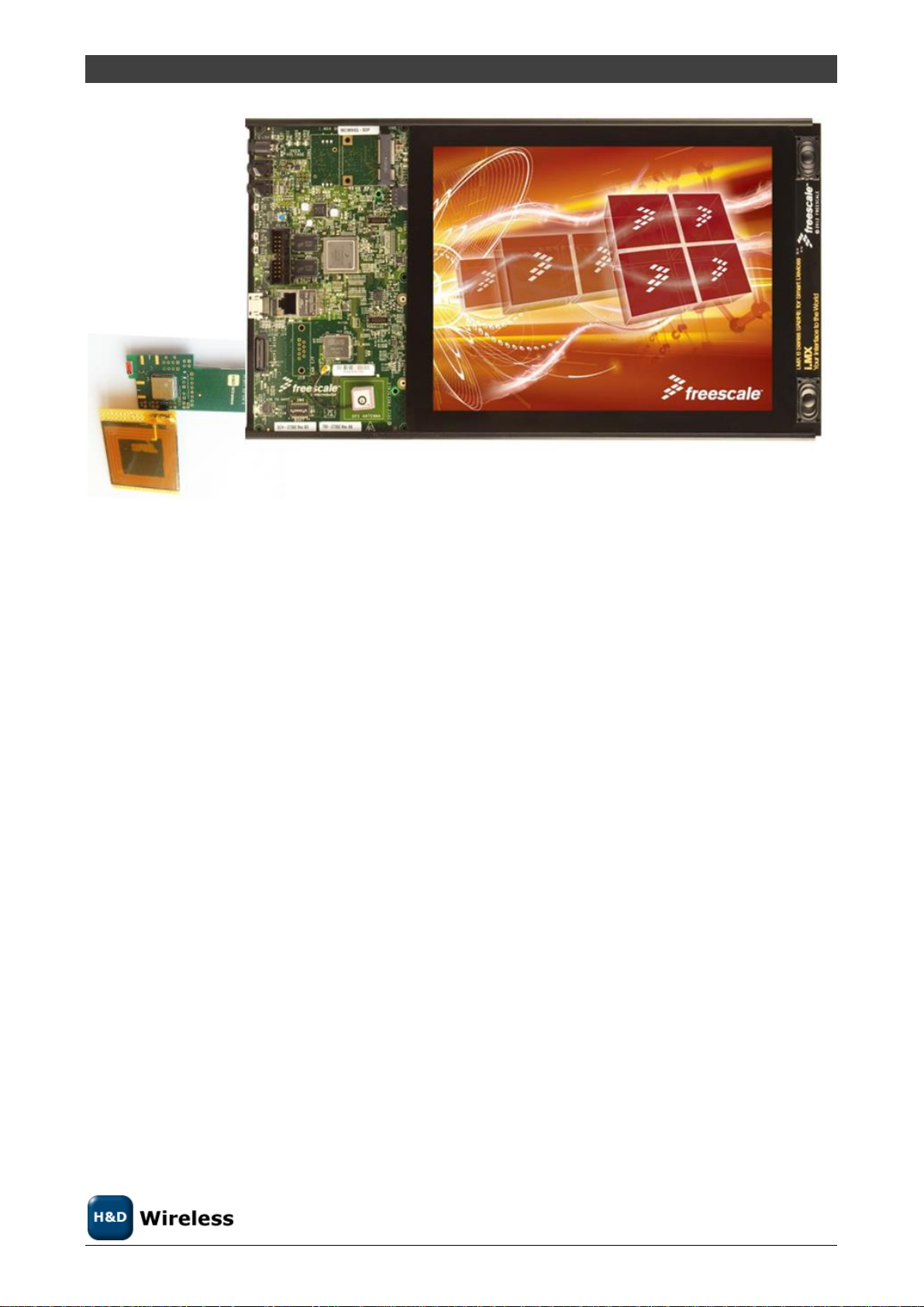
SPB209A-EVK is a complete WLAN/BT/NFC module with EMC shield, dual band antenna (WiFi and BT),
prepared for application specific NFC antenna and ready for quick validation in a hosted environment.
SPB209A-EVK features the SPB209A module mounted on a ready to run SD-card or SMD module for quick
product turn-around or SPB209A evaluation. It provides an ultra-low power, high performance and feature
rich client solution. It provides up to 433 Mbit/s data rate when operating in the OFDM mode and up to 11
Mbit/s data rate when operating in the DSSS/CCK mode.
SPB209A integrates RF, baseband/MAC, Bluetooth Package Engine, NFC, memory, RF filters, oscillator,
antenna or SMA connector and EMC shield into a highly integrated and optimized module solution with
high quality and reliability to a complete standalone solution with no need for external components.
This highly integrated solution is optimized for customer applications running on a Linux host platform.
The host interface supports SDIO 3.0, High Speed UART and I2C. Internal RAM comprises both code and
data memory eliminating the need for external RAM, Flash or ROM memory interfaces. MAC address,
trimming values etc. are stored in the on board memory.
1.1 Key Features
Support for 802.11a/b/g/n/ac
Data Rates: 20MHz CH 1-86Mbps; 40MHz CH 13-200Mbps; 80MHz CH 29-433Mbps
Modulation: BPSK, CCK, QPSK, 16QAM, 64QAM 256 QAM for WLAN and
GFSK/π/4DQPSK/8DPSK/LE
Open WEP, WPA/WPA2 encryption
No external components except for the antenna options
Low power consumption due to efficient PA design and power off mode
An on-board 32 kHz oscillator maintains real time in power save mode, allows the high
frequency clock to be turned off.
Supporting STA and AP operation mode
Supports BT-WLAN coexistence and ISM-LTE coexistence
Extensive DMA hardware support for data flow to reduce CPU load.
Advanced power management for optimum power consumption at varying load.
External interfaces 4 bit SDIO 3.0 for WLAN and UART/PCM for BT interface
On-board High Frequency High Precision Oscillator 37.4 MHz
Small footprint 14 x 14 mm (196 mm2) 41-pin
RoHS Compliant
Page 4
H&D Wireless AB, SPB209A Application Note page 4 ( 15)
1453- SPB209A Rev B
Copyright © 2013 H&D Wireless AB, All rights reserved
The SPB111 SD-card with SPB209A module and a custom NFC antenna connected to a i.MX6 DL
Linux Host Platform.
2 APPLICATION INFORMATION
2.1 Power Supply
SPB209A should be powered by a single supply voltage on VDD of 3.3V. It generates all required digital and
analog supply voltages with the built in DC-DC converter.
2.1.1 Main supply
The main power is connected to VDD. The ripple on VDD should be less than 10mV p-p.
2.2 Clock Signals
The SPB209A requires no external clock signals. It has an internal high frequency oscillator with a high
precision 37.4 MHz crystal and a low power oscillator to generate the required clock signals.
2.3 Standby
The Power Down pin (PDn) shall be set high during normal operation of either connectivity type. Pulling
PDn pin low, sets SPB209A in Standby mode. This turns OFF most parts of the circuit and minimizes the
current consumption. All I/O interface pins are set to predefined states (high, low or high-z) when in
Standby mode.
To end Standby mode set PDn high and reload firmware.
2.4 Power save
Page 5
H&D Wireless AB, SPB209A Application Note page 5 ( 15)
1453- SPB209A Rev B
Copyright © 2013 H&D Wireless AB, All rights reserved
Power save is an energy saving mode where SPB209A is only listening at regular intervals for the beacons
transmitted from an access point and is set in sleep mode in between. During this sleep mode, firmware is
kept in RAM but all not needed functions are turned off. Since the receive time is very short compared to
the listening interval the average current consumption is reduced significantly.
The timing of the listening interval is based on the low power oscillator clock generated internally.
2.5 Interfaces
The SPB209A is equipped with a number of interfaces that can be set up in various ways by the value on
GPIO2 and GPIO3 during boot, see section 2.5.1.
2.5.1 Host Interface SDIO and UART
The SDIO interface is SDIO 4-bit mode. For timing characteristics and trigger level see Fel! Hittar inte
referenskälla. and Fel! Hittar inte referenskälla., Fel! Hittar inte referenskälla., Fel! Hittar inte
referenskälla. and Fel! Hittar inte referenskälla..
The High Speed UART interface default supporting Baud Rates from 1200 up to 2764800 bps, 8 bits, no
parity, 1 stop bit.
Booth GPIO2 and GPIO3 have internal pull-up and only needs to be connected via a 100kOhm resistor to
GND to be set low (0). For high level (1) the pin can be left unconnected. Table 2-1 shows the different
options. The default is to leave GPIO2 and GPIO3 unconnected (11) and SDIO as host interface for all
services.
Table 2-1: Host Interface Selection
GPIO2
GPIO3
WLAN Host Interface
BT/BLE/NFC
Host Interface
FW Download
interface
FW Download
mode
0
0
SDIO
UART
SDIO
Serial
0
1
SDIO
SDIO
SDIO
Parallel
1
0
SDIO
UART
SDIO+UART
Parallel
1
1
SDIO
SDIO
SDIO
Serial
2.5.2 PCM Interface
2.5.3 PCM
PCM interface is used for BT audio and can operate in master or slave mode. The interface supports the
following:
- 8, 13, 14, 15 or 16-bit samples
- 4 slots per frame with up to 16-bits per slot
- Long or short frame sync
2.5.4 Host Wake up
Wake up command via the SDIO interface. This is the normal wake up and is implemented in the FW.
There is options to use defined GPIO:s for Host Wake-up or opposite for SPB209A Wake-Up involving both
WLAN, BT and NFC. Below table outline the options.
GPIO No.
Function
Page 6

H&D Wireless AB, SPB209A Application Note page 6 ( 15)
1453- SPB209A Rev B
Copyright © 2013 H&D Wireless AB, All rights reserved
GPIO1
WLAN to Host Wake-up
GPIO13
BT/NFC to Host Wake-up
GPIO14
Host to WLAN Wake-up
GPIO15
Host to BT/NFC Wake-up
2.5.5 NFC Wake up
The NFC support contactless wake up functionality giving a trigger on a GPIO pin depending on the activities
on the RF interface, when an antenna is connected to the NFC_ANT P and _N pins.
2.6 NFC Interface
The NFC Interface provides RFID and NFC functionality.
Supported features:
Protocol support fir ISO 14443A/B, ISO 15693, NFCIP-2, NFC-Forum, EMV contactless targets with a
data rate up to 848 Kbps.
Reader/Writer, Card Emulation and Peer-to-Peer (P2P) modes
Low Power and sleep modes
Programmable Carrier detection level for Card Emulation mode
Programmable field detection level for RF anti-collision when operating as Reader or Active Target.
The NFC chip can also be accessed via the I2C interface pin SDA and SCL provided that the SPB209A device
is powered. Support standard 100kHz and Fast 400kHz mode.
2.7 RF interface
The SPB209A EVK is prepared with a chip dual band antenna optimal for quick evaluation of the SPB209A
RF module.
Designing custom application board with the SPB209A RF module the following RF parametrical
requirements shall be considered:
The RF output pin impedance is 50 ohm and shall be connected to an antenna with VSWR better
than 2:1.
The RF antenna gain must be maximum 1.8 dBi for the 2.4 GHz band and equal or less than 4.9 dBi
for the 5GHz band.
A custom NFC antenna will need to be selected with a maximum size of 45 x 45 mm. NFC antenna is
soldered down with two pin interface to the side of the SPB209A EVK.
2.8 Operational Mode
2.8.1 General
The SPB209A can be operated as STA or AP using a Linux Host platform. The STA operation use the Linux
WPA supplicant and the AP operation us Linux HostAPD. RF testing and FCC/ETSI certification shall use
equivalent software tools provided by H&D Wireless Sales up on request.
Page 7

H&D Wireless AB, SPB209A Application Note page 7 ( 15)
1453- SPB209A Rev B
Copyright © 2013 H&D Wireless AB, All rights reserved
2.8.2 STA operation using WPA Supplicant
The wpa_supplicant is the IEEE 802.1X/WPA component used in the client stations. The WPA supplicant can
be configured to control the roaming and IEEE 802.11 authentication/association of the SPB209A device.
The configuration is usually performed in a configuration file, e.g. /etc/wpa_supplicant.conf. It is also
possible to directly issue commands to the WPA Supplicant, using a dedicated shell command, wpa_cli. The
usage of wpa_cli is out of the scope of this document, but is described in detail in the WPA supplicant
documentation http://hostap.epitest.fi/wpa_supplicant/.
Below list show supported WPA Supplicant network options
Key management (key_mgmt): WPA-PSK, NONE
Group key encryption (group): CCMP, TKIP
Pairwise key encryption (pairwise): CCMP, TKIP
Protocol (proto): WPA, WPA2
Below list show examples of instructions on how to perform the following operations using WPA
Supplicant
2.8.2.1 Connect to an unencrypted network
To simply instruct the WPA Supplicant to connect to any unencrypted network with ssid hdwireless, the
following configuration file should be enough:
ctrl_interface=/var/run/wpa_supplicant
network={
ssid="hdwireless"
key_mgmt=NONE
}
The path to the configuration file and the interface name (owl0) should then be passed as parameters when
starting the WPA Supplicant:
$ wpa_supplicant -Dwext -iowl0 -c /etc/wpa_supplicant.conf -B
The paramater -Dwext informs the WPA Supplicant that the standard Wireless Extensions interface should
be used to control the network interface. For detailed information on how to configure and run the WPA
supplicant, see the WPA supplicant documentationhttp://hostap.epitest.fi/wpa_supplicant/.
The WPA Supplicant will now periodically scan for networks until one that matches the configuration is found.
Once found, a connection will be established. The WPA Supplicant will also handle reconnect if the
connection is lost. Therefore, opposed to Wirieless Tools, when using the WPA Supplicant, it is not
necessary to perform manual scanning and network selection.
Page 8

H&D Wireless AB, SPB209A Application Note page 8 ( 15)
1453- SPB209A Rev B
Copyright © 2013 H&D Wireless AB, All rights reserved
Note that the WPA Supplicant configuration can hold several networks and the WPA Supplicant will choose
and roam amongst them. However, most importantly, the WPA supplicant implements the key negotiation
with a WPA Authenticators.
2.8.2.2 Connect to a WPA protected network that uses TKIP encryption
To connect to a network using WPA key management and TKIP encryption, the following network
configuration can be specified in the configuration file:
ctrl_interface=/var/run/wpa_supplicant
network={
ssid="hdwireless"
key_mgmt=WPA-PSK
group=TKIP
pairwise=TKIP
proto=WPA
psk="hdwirelesskey"
}
The key configured on the access point should be "hdwirelesskey".
To force the WPA Supplicant to re-read its configuration file wpa_cli can be used
$ wpa_cli reconfigure
One should remember that all wireless operations performed by both the WPA supplicant and Wireless Tools
are done through the same Wireless Extensions API. This means that it will still be possible to e.g. check the
connection status with iwconfig:
$ iwconfig
owl0 IEEE 802.11bg ESSID:"angr"
Mode:Managed Frequency:2.422 GHz Access Point:68:7F:74:10:5B:4C
Bit Rate=54 Mb/s
Encryption key:472A-7E38-C465-D4EB-6DA7-BAE6-4700-0960-EDB1-40DE-
18CC-5A02-4AE1-EA96-F3EE-142A Security mode:open
Page 9

H&D Wireless AB, SPB209A Application Note page 9 ( 15)
1453- SPB209A Rev B
Copyright © 2013 H&D Wireless AB, All rights reserved
Power Management timeout:10
Link Quality=24/30 Signal level=-20 dBm Noise level=-44 dBm
Rx invalid nwid:0 Rx invalid crypt:0 Rx invalid frag:0
Tx excessive retries:0 Invalid misc:0 Missed beacon:0
Once connected, it is possible to obtain an ip address and perform the ping test:
$ udhcpc -i owl0
Sending discover...
Sending select for 192.168.2.102...
Lease of 192.168.2.102 obtained, lease time 172800
adding dns 192.168.2.1
$ ping -c 3 192.168.2.1
2.8.2.3 Connect to a WPA2 enabled network that uses CCMP encryption
To connect to a network using the WPA2 protocol and CCMP encryption, the following network configuration
can be specified in the configuration file:
ctrl_interface=/var/run/wpa_supplicant
network={
ssid="hdwireless"
key_mgmt=WPA-PSK
group=CCMP
pairwise=CCMP
proto=WPA2
psk="hdwirelesskey"
}
Page 10

H&D Wireless AB, SPB209A Application Note page 10 ( 15)
1453- SPB209A Rev B
Copyright © 2013 H&D Wireless AB, All rights reserved
2.8.2.4 Connect to a network that uses any WPA/WPA2 protocol and TKIP/CCMP
encryption
Note that several encryption parameters can be specified on a single line, allowing connections to a specific
ssid using a range of encryption methods. The configuration file below should allow connections to the
hdwireless access point regardless of whether the WPA or WPA2 protocol is used or whether CCMP or TKIP
is used for pairwise and group key encryption. The actual encryption method used will be the most secure
one that is supported by the access point.
ctrl_interface=/var/run/wpa_supplicant
network={
ssid="hdwireless"
key_mgmt=WPA-PSK
group=TKIP CCMP
pairwise=TKIP CCMP
proto=WPA WPA2
psk="hdwirelesskey"
}
2.8.2.5 Connect to a network with hidden SSID
To allow the wpa_supplicant to connect to hidden networks, the scan_ssid parameter must be added to the
network configuration.
ctrl_interface=/var/run/wpa_supplicant
network={
ssid="hdwireless"
scan_ssid=1
key_mgmt=WPA-PSK
group=TKIP CCMP
pairwise=TKIP CCMP
proto=WPA WPA2
psk="hdwirelesskey"
Page 11

H&D Wireless AB, SPB209A Application Note page 11 ( 15)
1453- SPB209A Rev B
Copyright © 2013 H&D Wireless AB, All rights reserved
}
2.8.2.6 List of supported WPA Supplicant network options
Key management (key_mgmt): WPA-PSK, NONE
Group key encryption (group): CCMP, TKIP
Pairwise key encryption (pairwise): CCMP, TKIP
Protocol (proto): WPA, WPA2
2.8.3 AP operation using HostAPD
Currently there is only hw support for the Linux driver with SDIO interface for SAPB209A.
Linux kernel version 4.0 or higher is required supporting DFS operation in 5GHz band
required for AP mode operation.
The Linux driver consist of four kernel objects: mwifiex.ko, mwifiex_sdio.ko, btmrvl.ko and
btmrvl_sdio.ko.
mwifiex.ko and mwifiex_sdio.ko handles the wifi protocols, while btmrvl.ko and btmrvl_sdio.ko
handles Bluetooth, BLE and NFC.
Along with the driver goes a fw binary that is downloaded to the chip by the driver. It must be
named sd8887_uapsta.bin and located at /lib/firmware/mrvl/
HOWTO run Linux softAP with hostapd
1. Make sure the network manager is disabled with regards to wifi:
2. Make sure the radio interface is unblocked:
Page 12

H&D Wireless AB, SPB209A Application Note page 12 ( 15)
1453- SPB209A Rev B
Copyright © 2013 H&D Wireless AB, All rights reserved
3. rfkill unblock all
3. Download the attachment:hostapd.conf file to the local disk.
4. Install Linux Wifi host AP package:
5. sudo apt-get install hostapd
5. Plugin the sdio module.
Make sure mwifiex driver was successfully started by typing:
6. iwconfig mlan0
This command should display information about the mlan0 interface
6. mwifiex driver does not support ap mode on native interface, so an additional ap-
dedicated interface must be created.
In order to do so we need to find out the phy<n> enum for the mlan0 interface by
typing:
7. iw list | grep Wiphy
Normally phy0 corresponds to builtin wlan0, and the next higher enum will correspond to
mlan0
7. Now create the ap specific interface (uap0) by typing
8. sudo iw phy phy<n> interface add uap0 type __ap
Where <n> is the enum found out from iw list command
8. Now configure the AP by editing the hostapd.conf file.
Example: For 11n, 5GHz band, channel 36, DFS enabled: Search for and edit the follwing
parameters in hostapd.conf file:
interface=uap0
ssid=<desired-ssid>
hw_mode=a
channel=<desired channel>
wmm_enabled=1
ieee80211n=1
ieee80211d=1
ieee80211h=1
country_code=<country_code>
Page 13

H&D Wireless AB, SPB209A Application Note page 13 ( 15)
1453- SPB209A Rev B
Copyright © 2013 H&D Wireless AB, All rights reserved
Valid <country_code>'s are:
US # US FCC
CA # IC Canada
EU # ETSI
ES # Spain
FR # France
JP # Japan
CN # China
9. Start the AP by typing:
10. sudo hostapd <hostapd_config_file_name>
AP should now be up and running
10. To run traffic, assign a fixed ip address to the interface:
11. sudo ifconfig uap0 <dersired ip> #e.g. 192.168.10.1
12. Associate a station and assign a static ip at the same subnet
12. To remove the uap0 interface, kill the hostapd process and run:
13. sudo iw dev uap0 del
3 Regulatory
Country
Approval
authority
Regulatory
Frequency band
USA
FCC
FCC ID: XO2SPB209A
2.412 GHz -2.462 GHz
5.250 GHz – 5.725 GHz
Europe
National
ETSI/EN
2.412 GHz -2.4835 GHz
5.150 GHz – 5.725 GHz
Table 3-1: Regulatory standards
3.1 FCC (United States of America)
This equipment complies with Part 15 of the FCC rules and regulations.
To fulfill FCC Certification requirements, an OEM manufacturer must comply with the following regulations:
Page 14

H&D Wireless AB, SPB209A Application Note page 14 ( 15)
1453- SPB209A Rev B
Copyright © 2013 H&D Wireless AB, All rights reserved
1. The modular transmitter must be labeled with its own FCC ID number, and, if the FCC ID is not visible
when the module is installed inside another device, then the outside of the device into which the module is
installed must also display a label referring to the enclosed module. This exterior label can use wording
such as the following:
Example of label required for OEM product containing SPB209A module
2. Only antennas approved may be used with the SPB209A module. The SPB209A module may be
integrated with custom design antennas which OEM installer must authorize following the FCC 15.21
requirements.
IMPORTANT: This equipment complies with Part 15 of the FCC Rules. Operation is subject to the following
two conditions: (1) this device may not cause harmful interference, and (2) this device must accept any
interference received, including interference that may cause undesired operation (FCC 15.19).
The internal / external antenna(s) used for this mobile transmitter must provide a separation distance of at
least 20 cm from all persons and must not be co-located or operating in conjunction with any other
antenna or transmitter.
This device is approved as a mobile device with respect to RF exposure compliance, and may only be
marketed to OEM installers. Use in portable exposure conditions (FCC 2.1093) requires separate equipment
authorization.
IMPORTANT: Modifications not expressly approved by this company could void the user's authority to
operate this equipment (FCC section 15.21).
IMPORTANT: The finished product is required to comply with all applicable FCC equipment authorizations
regulations, requirements and equipment functions not associated with the transmitter module portion.
Compliance for unintentional radiators (Part 15 Subpart B “Unintentional Radiators”), such as digital
devices, computer peripherals, radio receivers, etc. has to be demonstrated.
3.2 ETSI (Europe)
The SPB209A module has been certified for use in European union countries according to ETSI EN 300 328
(Electromagnetic compatibility and Radio spectrum matters for equipment operating in the 2,4 GHz ISM
band using spread spectrum modulation techniques). This standard is harmonized within the European
Union and covering essential requirements under article 3.2 of the R&TTE-directive.
If the SPB209A module are incorporated into a product, the manufacturer must ensure compliance of the
final end-user product to the European harmonized EMC and low voltage/safety standards. A declaration of
conformity must be issued for the product including compliance references to these standards. Underlying
the declaration of conformity a technical construction file (TCF), including all relevant test reports and
technical documentation, must be issued and kept on file as described in Annex II of the R&TTE-directive.
Page 15

H&D Wireless AB, SPB209A Application Note page 15 ( 15)
1453- SPB209A Rev B
Copyright © 2013 H&D Wireless AB, All rights reserved
Furthermore, the manufacturer must maintain a copy of the SPB209A module documentation and ensure
the final product does not exceed the specified power ratings, antenna specifications, and/or installation
requirements as specified in the user manual. If any of these specifications are exceeded in the final
product, a complete re-test must be made in order to comply with all relevant standards as basis for CEmarking. A submission to notified body must be used only if deviations from standards have been found or
if non-harmonized standards have been used.
 Loading...