

Page 1

BOX860-WiFi 802.11b/g/n Interactive Toy
Data Sheet
BOX860
WiFi Interactive Toy
Page 2

Data Sheet 1451- Data Sheet BOX860
Revision
Revision date
Description
PA1
2015-05-04
First Draft
PA2
PA3
2015-08-26
Added radio restrictions, battery box label, updated flammability
class
A
2015-12-09
Release A
Revision History
Disclaimer and copyright notice
Information in this document, including URL references, is subject to change without notice.
THIS DOCUMENT IS PROVIDED "AS IS" WITH NO WARRANTIES WHATSOEVER, INCLUDING ANY WARRANTY
OF MERCHANTABILITY, NONINFRINGEMENT, FITNESS FOR ANY PARTICULAR PURPOSE, OR ANY WARRANTY
OTHERWISE ARISING OUT OF ANY PROPOSAL, SPECIFICATION OR SAMPLE. All liability, including liability for
infringement of any proprietary rights, relating to use of information in this document is disclaimed.
No licenses express or implied, by estoppel or otherwise, to any intellectual property rights are granted
herein.
The Wi-Fi Alliance Member Logo is a trademark of the Wi-Fi Alliance.
All trade names, trademarks and registered trademarks mentioned in this document are property of their
respective owners, and are hereby acknowledged.
Copyright © 2015 H&D Wireless AB. All rights reserved.
Rev. A Dec-2015 Data Sheet 1451-BOX860 page 2 (18)
Confidential
Page 3

Data Sheet 1451- Data Sheet BOX860
CONTENT
1 INTRODUCTION ................................................................................................................... 5
1.1 Overview 5
1.2 Key Features ............................................................................................................................................................. 5
2 HARDWARE ARCHITECTURE ................................................................................................. 6
2.1 Block Diagram ................................................................................................................................ .......................... 6
2.2 Order information ................................................................................................................................................... 6
3 ELECTRICAL DATA ................................................................................................................ 7
3.1 Absolute maximum ratings ..................................................................................................................................... 7
3.2 Electro Static Discharge (ESD) ............................................................................................................................... 7
3.3 Recommended operating conditions ...................................................................................................................... 7
3.4 Power Consumption ................................................................................................................................ ................. 7
3.5 RF Performance ....................................................................................................................................................... 8
4 INTERFACES ....................................................................................................................... 10
4.1 Tactile switches ....................................................................................................................................................... 10
4.2 LED 10
4.3 Speaker 10
4.4 Microphone ............................................................................................................................................................. 10
5 MECHANICAL .................................................................................................................... 11
5.1 Main enclosure ....................................................................................................................................................... 11
5.2 Battery box ............................................................................................................................................................. 11
5.3 Tactile switches ....................................................................................................................................................... 12
6 APPLICATION INFORMATION ............................................................................................. 13
6.1 Power Supply .......................................................................................................................................................... 13
6.2 Power on/off ............................................................................................................................................................ 13
6.3 Configuration ......................................................................................................................................................... 13
6.4 Record 13
6.5 Playback 13
6.6 Environmental statement ...................................................................................................................................... 13
6.7 Markings on the BOX860 ...................................................................................................................................... 13
Rev. A Dec-2015 Data Sheet 1451-BOX860 page 3 (18)
Confidential
Page 4

Data Sheet 1451- Data Sheet BOX860
6.8 Markings on the Battery Box ................................................................................................................................ 14
7 STANDARDS COMPLIANCE ................................................................................................. 15
7.1 IEEE/IETF ............................................................................................................................................................. 15
7.2 WiFi Alliance .......................................................................................................................................................... 15
7.1 Regulatory .............................................................................................................................................................. 15
8 RELATED DOCUMENTS ...................................................................................................... 18
9 TRADEMARKS .................................................................................................................... 18
10 SALES OFFICES ................................................................................................................... 18
Rev. A Dec-2015 Data Sheet 1451-BOX860 page 4 (18)
Confidential
Page 5
Data Sheet 1451- Data Sheet BOX860
1 INTRODUCTION
1.1 Overview
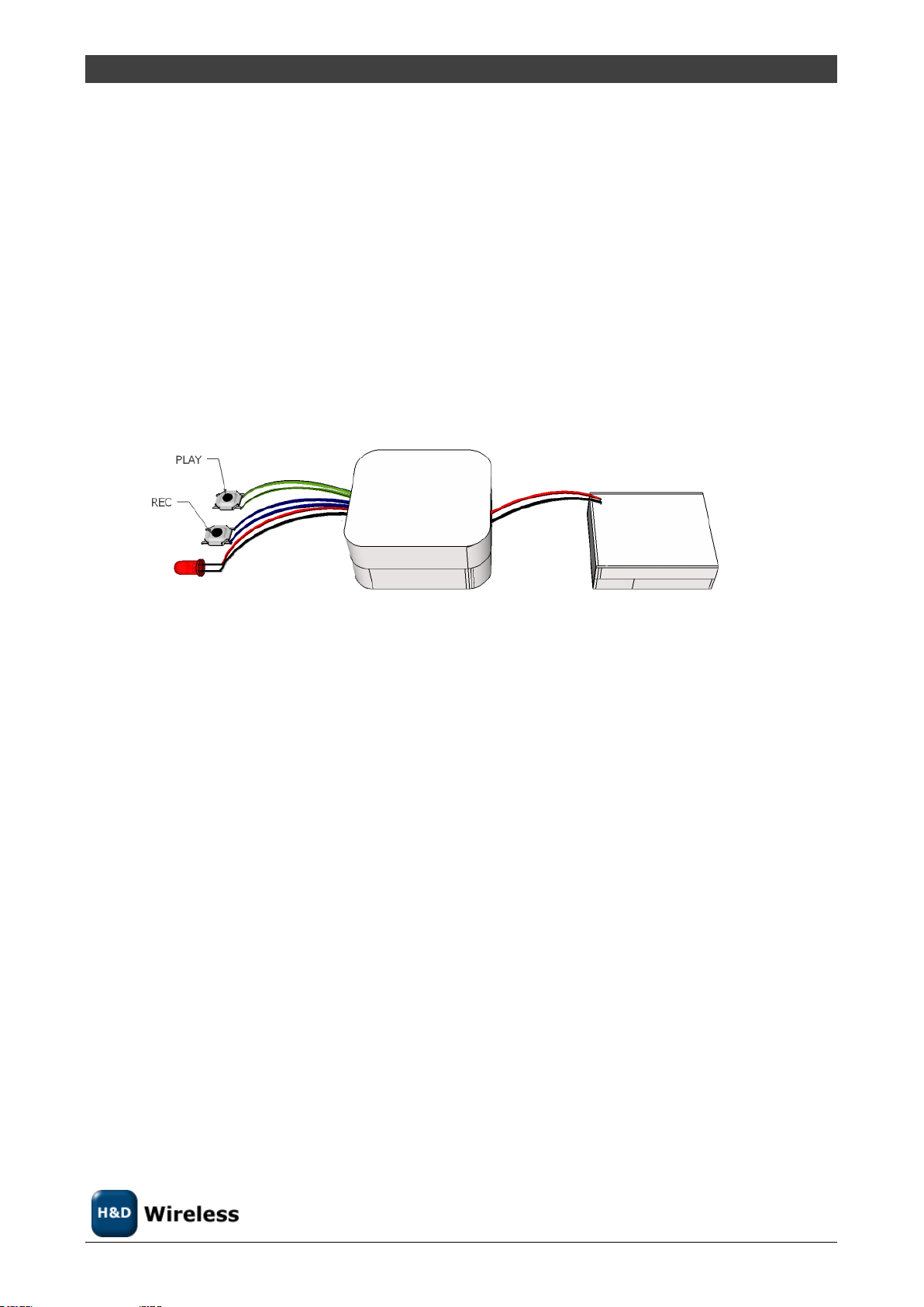
BOX860 is one of the end nodes of an easy to use messaging system based on WLAN. The other end is a
smartphone APP. The BOX860 is intended to be placed inside a toy.
The simple user interface consists of two tactile switches and a LED. The switches controls the recording
and playback of messages and the LED signals the presence of a new message.
BOX860 has a built in Access Point capability to enable quick and easy configuration into the end users
network.
This data sheet pertains to hardware revision R2A and later of the BOX860.
1.2 Key Features
WLAN 802.11 b/g/n radio modem for 2.4GHz ISM band.
Data Rates: 1, 2, 5.5, 6, 7.2, 9, 11, 12, 14.4, 18, 21.7, 24, 28.9, 36, 43.3, 48, 54, 57.8, 65 Mbps
Modulation: QPSK, 16QAM, 64QAM DBPSK, DQPSK, CCK, OFDM with BPSK
Open WEP, WPA/WPA2 encryption
Operates in station or access point mode
Low power consumption
Built in speaker and microphone
Simple configuration and control via smartphone App
Single Supply Voltage by 3xAA batteries in separate enclosure
RoHS Compliant
Integrated antenna
Rev. A Dec-2015 Data Sheet 1451-BOX860 page 5 (18)
Confidential
Page 6
Data Sheet 1451- Data Sheet BOX860
Order number
Description
MOQ
BOX860
BOX860 with battery case and wiring
100
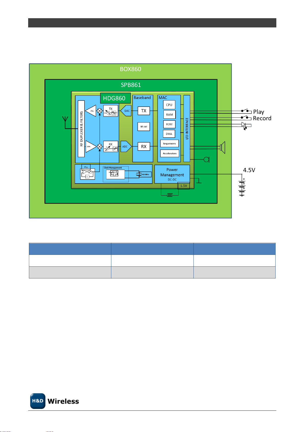
2 HARDWARE ARCHITECTURE
2.1 Block Diagram
Figure 2-1 Block Diagram:
2.2 Order information
Table 2.1: Ordering Information
Rev. A Dec-2015 Data Sheet 1451-BOX860 page 6 (18)
Confidential
Page 7

Data Sheet 1451- Data Sheet BOX860
Rating
Min
Max
Unit
Supply voltage
-0.3
4.5
V
Input RF level
10
dBm
Storage temperature
0
+50
o
C
Symbol
Min
Typ.
Max
Unit
VCC
Supply Voltage
3.0 4.5
V
TOP
Operating temperature
0 50 oC
Indoor use or corresponding
temperature and humidity conditions
Mode
Conditions
Min
Typ.
Max
Unit
Peak current
All modes
300
mA
TX [802.11b]
CCK 11Mbps
205
230
mA
TX [802.11g]
OFDM 54 Mbps
165
200
mA
TX [802.11n]
OFDM 65 Mbps
140
170
mA
RX [802.11b]
Max sensitivity
53
59
mA
RX [802.11g]
Max sensitivity
56
64
mA
RX [802.11n]
Max sensitivity
56
64
mA
Record
WiFi Associated
58 mA
Playback
WiFi Associated
70 mA
Idle
Between check for
messages
0.2
mA
3 ELECTRICAL DATA
3.1 Absolute maximum ratings
Table 3.1: Absolute maximum ratings. Exceeding any of the maximum ratings, even briefly lead to deterioration in
performance or even destruction. Values indicates condition applied one at the time.
3.2 Electro Static Discharge (ESD)
BOX860 withstands ESD voltages up to 2000V HBM (Human Body Model) according to JESD22-A114 and up
to 300 V CDV (Charged Device Model) according to JESD22-A115.
3.3 Recommended operating conditions
Table 3.2: Recommended operating conditions
3.4 Power Consumption
If no other conditions are started does VDD=3.6V, T
= 25oC apply.
amb
Rev. A Dec-2015 Data Sheet 1451-BOX860 page 7 (18)
Confidential
Page 8

Data Sheet 1451- Data Sheet BOX860
Parameter
Conditions
Min
Typical
Max
Units
Frequency range
ETSI1
2412
2484
MHz
FCC1
2412
2462
Supported Channels
ETSI1
Ch.1
(2412
MHz)
Ch. 13
(2472
MHz)
FCC1
Ch.1
(2412
MHz
Ch. 11
(2462
MHz)
Transmitter performance
1
Output power
CCK 1 Mbit/s
+15
+16
+17
dBm
Output power
CCK 11 Mbit/s
+15
+16
+17
dBm
Output power
OFDM 6 Mbit/s
+13
+14
+15
dBm
Output power
OFDM 54Mbit/s
+13
+14
+15
dBm
Output power
HT20 MSC0-MSC6
+10
+11
+12
dBm
Receiver performance 11b/g, T
amb
= 25oC
Receiver sensitivity
DSSS 1Mbit/s
-94
-87
dBm
Receiver sensitivity
DSSS 2Mbit/s
-91
-85
dBm
Receiver sensitivity
CCK 5.5Mbit/s
-89
-84
dBm
Receiver sensitivity
CCK 11Mbit/s
-86
-81
dBm
Receiver sensitivity
BPSK 6Mbit/s
-89
-84
dBm
Receiver sensitivity
BPSK 9Mbit/s
-88
-83
dBm
Receiver sensitivity
QPSK 12Mbit/s
-86
-81
dBm
Receiver sensitivity
QPSK 18Mbit/s
-84
-79
dBm
Receiver sensitivity
16QAM 1/2 24Mbit/s
-82
-76
dBm
Receiver sensitivity
16QAM 3/4 36Mbit/s
-79
-72
dBm
Receiver sensitivity
64QAM 2/3 48Mbit/s
-74
-68
dBm
Receiver sensitivity
64QAM 3/4 54Mbit/s
-72
-67
dBm
Receiver performance 11n, T
amb
= 25
o
C
Receiver sensitivity
OFDM/BPSK 7.2Mbit/s
-90
-83
dBm
Receiver sensitivity
OFDM/BPSK 14.4Mbit/s
-88
-80
dBm
Table 3.3: Current consumption in different modes.
Notes:
1) WLAN in power save mode listening to access point beacons.
3.5 RF Performance
Conditions: VBAT= 3.6V, Tamb= 25°C Spectrum Mask and BER according to IEEE 802.11b/g/n specification.
Rev. A Dec-2015 Data Sheet 1451-BOX860 page 8 (18)
Confidential
Page 9

Data Sheet 1451- Data Sheet BOX860
Receiver sensitivity
OFDM/BPSK 21.7Mbit/s
-86
-78
dBm
Receiver sensitivity
OFDM/16-QAM 28.9Mbit/s
-83
-75
dBm
Receiver sensitivity
OFDM/16-QAM 43.4Mbit/s
-79
-71
dBm
Receiver sensitivity
OFDM/64-QAM 57.8Mbit/s
-72
-67
dBm
Receiver sensitivity
OFDM/64-QAM 65Mbit/s
-70
-66
dBm
Table 3.4: RF performance.
1) BOX860 products sold for final use in North America has the Operations Region set to FCC in the
OTP memory. This limits the use of frequencies to those allowed in FCC Part15 and backs down the
TX power at the band edges.
2) TX output power varies with temperature as shown in Figure 3-1
Figure 3-1: Pout vs ambient temperature
3) TX Output power varies with temperature as shown in Figure 3-2
Figure 3-2: Output Power vs. VCC voltage
3.5.1 Batteries
The BOX860 is designed to use 3x1.5V size-AA/LR6 alkaline batteries as voltage supply.
Other types of batteries may affect the function and in worst case cause damage to the electronics.
Rev. A Dec-2015 Data Sheet 1451-BOX860 page 9 (18)
Confidential
Page 10

Data Sheet 1451- Data Sheet BOX860
4 Interfaces
4.1 Tactile switches
The BOX860 has two tactile switches. The switches are mounted on two 350mm wires, signal and ground,
and creates a short to ground when pressed.
The switches are to be placed so that the end user can access them easily, for example in the paws of a
stuffed toy animal.
The PLAY switch is to be placed in the right paw of the toy.
The REC switch is to be placed in the left paw of the toy.
4.2 LED
The BOX860 has a single red LED. It is mounted on 350mm long wires to allow it to be placed at a visible
location on the toy.
4.3 Speaker
The BOX860 has a 2” speaker mounted inside the main enclosure.
4.4 Microphone
The microphone is mounted on the PCB.
Rev. A Dec-2015 Data Sheet 1451-BOX860 page 10 (18)
Confidential
Page 11

Data Sheet 1451- Data Sheet BOX860
5 Mechanical
5.1 Main enclosure
The main enclosure host the circuit board and speaker, its dimensions is shown in Figure 5-1
Figure 5-1: Main enclosure dimensions
The main enclosure is latched with two screws.
The main enclosure is made of polyethylene with flammability class V-2.
5.2 Battery box
The battery box holds three AA/LR6 size batteries and is permanently connected to the main enclosure
with two 200mm wires.
Figure 5-2: Battery Box dimensions
Rev. A Dec-2015 Data Sheet 1451-BOX860 page 11 (18)
Confidential
Page 12

Data Sheet 1451- Data Sheet BOX860
The Battery Box has an on/off switch located on the top side upper left corner. The battery compartment is
latched by a screw.
The Battery Box is made of polyethylene with flammability class V-2
5.3 Tactile switches
The two tactile switches are of the same type. Two wires of 350mm connects the switch to the PCB.
Figure 5-3: Tactile switch dimensions
Rev. A Dec-2015 Data Sheet 1451-BOX860 page 12 (18)
Confidential
Page 13

Data Sheet 1451- Data Sheet BOX860
6 APPLICATION INFORMATION
6.1 Power Supply
BOX860 should be powered by 4.5V by three alkaline AA/LR& size batteries. The 1.5V batteries are inserted
in series in the Battery Box to generate the 4.5V.
6.2 Power on/off
The BOX860 is turned on by sliding the switch in the Battery BOX to its “ON” position and turned off by
sliding the switch into its “OFF” position.
6.3 Configuration
When the BOX860 has no configuration it starts in Access Point mode with the SSID:TOY-xx-yy-zz where xxyy-zz are the last six digits of the MAC address. A Smart Phone with the corresponding APP can then
associate to the BOX860 and configure it to the network to use and “pair” itself with the BOX860.
6.4 Record
After configuration messages to the APP can be recorded by pressing the REC switch. When the REC switch
is pressed once the LED starts blinking and the message is recorded until the REC switch is pressed again or
the max message length is reached. Once the message is recorded it is sent to the server for forwarding to
the APP. In local mode the message is delivered to the APP directly.
6.5 Playback
When the BOX860 receives a message the LED will start to blink. To listen to the message the PLAY switch is
pressed. After a message has been recorded it can be listen to by pressing the PLAY switch.
6.6 Environmental statement
The BOX860 is designed and manufactured to comply with the RoHS and Green directives.
6.7 Markings on the BOX860
The label is imprinted with the FCC ID and serial number. See example below:
Rev. A Dec-2015 Data Sheet 1451-BOX860 page 13 (18)
Confidential
Page 14

Data Sheet 1451- Data Sheet BOX860
6.8 Markings on the Battery Box
As the battery box normally is the easy accessible part of the system the data is also available on the
battery box label.
Rev. A Dec-2015 Data Sheet 1451-BOX860 page 14 (18)
Confidential
Page 15

Data Sheet 1451- Data Sheet BOX860
Standard
Notes
802.11b
Rates: 1, 2, 5.5, 11 Mbps
802.11d
International (country-to-country) roaming extensions
802.11g
Rates: 6, 9, 12, 18, 24, 36, 48, 54 Mbps
802.11i
Enhanced security
802.11j
Extensions for Japan
802.11n
Rates: 7.2, 14.4, 21.7, 28.9, 43.3, 57.8, 65
Specification
Notes
WiFi 802.11n STA
WPS2.0
Country
Approval
authority
Regulatory
Frequency band
USA
FCC
FCC ID: XO2BOX860
2.412 GHz -2.462 GHz
Canada
IC
IC: 8713A-BOX860
2.412 GHz -2.462 GHz
Europe
Self Certification
ETSI
2.412 GHz -2.4835 GHz
7 STANDARDS COMPLIANCE
7.1 IEEE/IETF
Table 7.1: Applicable IEEE standards
7.2 WiFi Alliance
Table 7.2: Applicable WiFi Alliance standards
7.1 Regulatory
Table 7.3: Regulatory standards
7.1.1 FCC (United States of America)
This equipment complies with Part 15 of the FCC rules and regulations.
To fulfill FCC Certification requirements, an OEM manufacturer must comply with the following regulations:
The modular transmitter is labeled with its own FCC ID number, and, if the FCC ID is not visible when the
module is installed inside another device, then the outside of the device into which the module is installed
must also display a label referring to the enclosed module. This exterior label can use wording such as the
following:
Rev. A Dec-2015 Data Sheet 1451-BOX860 page 15 (18)
Confidential
Page 16

Data Sheet 1451- Data Sheet BOX860
Example of label required for OEM product containing BOX860
NOTE: Only the built in antenna is approved for used with BOX860.
IMPORTANT: This equipment complies with Part 15 of the FCC Rules. Operation is subject to the following
two conditions: (1) this device may not cause harmful interference, and (2) this device must accept any
interference received, including interference that may cause undesired operation (FCC 15.19).
IMPORTANT: This device is approved as a portable device with respect to RF exposure compliance and
when the BOX860 is installed in its final casing the BOX860 has to be placed so that the distance between
the antenna and any body part of the end user is always greater than 27mm.
IMPORTANT: Modifications not expressly approved by this company could void the user's authority to
operate this equipment (FCC section 15.21).
IMPORTANT: The transmitter module may not be co-located with any other transmitter or antenna.
IMPORTANT: The finished product is required to comply with all applicable FCC equipment authorizations
regulations, requirements and equipment functions not associated with the transmitter module portion.
Compliance for unintentional radiators (Part 15 Subpart B “Unintentional Radiators”), such as digital
devices, computer peripherals, radio receivers, etc. has to be demonstrated.
7.1.2 IC (Canada)
Equipment is subject to certification under the applicable RSSs, shall be permanently labeled on each item,
or as an inseparable combination. The label must contain the following information for full compliance:
IMPORTANT: This equipment for which a certificate has been issued is not considered certified if it is not
properly labeled. The information on the Canadian label can be combined with the manufacturer's other
labeling requirements
IMPORTANT: Operation is subject to the following two conditions: (1) this device may not cause harmful
interference, and (2) this device must accept any interference received, including interference that may
cause undesired operation.
IMPORTANT: The transmitter module may not be co-located with any other transmitter or antenna.
IMPORTANT: To reduce potential radio interference to other users, the antenna type and its gain should be
so chosen that the equivalent isotropically radiated power (e.i.r.p.) is not more than that permitted for
successful communication.
Rev. A Dec-2015 Data Sheet 1451-BOX860 page 16 (18)
Confidential
Page 17

Data Sheet 1451- Data Sheet BOX860
IMPORTANT: The installer of this radio equipment must ensure that the antenna is located or pointed such
that it does not emit RF field in excess of Health Canada limits for the general population. Consult Safety
Code 6, obtainable from Health Canada's website www.hc-sc.gc.ca/rpb.
7.1.3 ETSI (Europe)
The BOX860P module has been certified for use in European union countries according to ETSI EN 300 328
(Electromagnetic compatibility and Radio spectrum matters for equipment operating in the 2,4 GHz ISM
band using spread spectrum modulation techniques). This standard is harmonized within the European
Union and covering essential requirements under article 3.2 of the R&TTE-directive.
If the BOX860P module are incorporated into a product, the manufacturer must ensure compliance of the
final end-user product to the European harmonized EMC and low voltage/safety standards. A declaration of
conformity must be issued for the product including compliance references to these standards. Underlying
the declaration of conformity a technical construction file (TCF), including all relevant test reports and
technical documentation, must be issued and kept on file as described in Annex II of the R&TTE-directive.
Furthermore, the manufacturer must maintain a copy of the BOX860P module documentation and ensure
the final product does not exceed the specified power ratings, antenna specifications, and/or installation
requirements as specified in the user manual. If any of these specifications are exceeded in the final
product, a complete re-test must be made in order to comply with all relevant standards as basis for CEmarking. A submission to notified body must be used only if deviations from standards have been found or
if non-harmonized standards have been used.
Rev. A Dec-2015 Data Sheet 1451-BOX860 page 17 (18)
Confidential
Page 18

Data Sheet 1451- Data Sheet BOX860
8 Related Documents
9 Trademarks
Wi-Fi is a trademark of the Wi-Fi Alliance
10 SALES OFFICES
Global Sales Office Sweden
H&D Wireless AB
H&D Wireless AB
Norgegatan 1
164 32 Kista
Sweden
E-mail: info@hd-wireless.se
Support: support@hd-wireless.se
Home page: www.hd-wireless.se
Local sales offices and representatives see www.hd-wireless.se
Rev. A Dec-2015 Data Sheet 1451-BOX860 page 18 (18)
Confidential
 Loading...