

Page 1
30" (76.2 CM) AND 36" (91.4 CM) ELECTRIC COOKTOP
INSTALLATION INSTRUCTIONS
INSTRUCTIONS D'INSTALLATION DE LA
TABLE DE CUISSON ÉLECTRIQUE DE 30" (76,2 CM)
ET DE 36" (91,4 CM)
Table of Contents/Table des matières
COOKTOP SAFETY........................................................................1
INSTALLATION INSTRUCTIONS..................................................2
Tools and Parts ............................................................................2
Location Requirements................................................................2
Electrical Requirements ..............................................................3
Install Heat Shield.........................................................................3
Install Foam Strip .........................................................................4
Install Cooktop .............................................................................4
Make Electrical Connection .........................................................5
Attach Cooktop to Countertop ....................................................6
Complete Installation ...................................................................6
COOKTOP SAFETY
SÉCURITÉ DE LA TABLE DE CUISSON ......................................7
INSTRUCTIONS D'INSTALLATION...............................................7
Outillage et pièces........................................................................7
Exigences d'emplacement...........................................................7
Spécifications électriques ...........................................................9
Installation de l'écran thermique..................................................9
Installation de la bande de mousse ...........................................10
Installation de la table de cuisson..............................................10
Raccordement électrique...........................................................11
Fixation de la table de cuisson au plan de travail......................12
Achever l'installation ..................................................................12
Your safety and the safety of others are very important.
We have provided many important safety messages in this manual and on your appliance. Always read and obey all safety
messages.
This is the safety alert symbol.
This symbol alerts you to potential hazards that can kill or hurt you and others.
All safety messages will follow the safety alert symbol and either the word “DANGER” or “WARNING.”
These words mean:
You can be killed or seriously injured if you don't immediately
DANGER
WARNING
All safety messages will tell you what the potential hazard is, tell you how to reduce the chance of injury, and tell you what can
happen if the instructions are not followed.
IMPORTANT:
Save for local electrical inspector's use.
follow instructions.
can be killed or seriously injured if you don't
You
instructions.
follow
IMPORTANT :
À conserver pour consultation par l'inspecteur local des installations électriques.
W10098720
Page 2

INSTALLATION INSTRUCTIONS
Tools and Parts
Gather the required tools and parts before starting installation.
Read and follow the instructions provided with any tools listed
here.
Too ls neede d
■ Tap e me as ure
■ Flat-blade screwdriver
■ Phillips head screwdriver
■ Hand or electric drill
■ Level
Parts supplied
■ Clamping brackets (2)
■ 2¹⁄₂" (6.4 cm) clamping screws (4) and washers (4)
■ #8 x ³⁄₈" (9.5 mm) sheet metal screws (4)
■ Heat shield (attached to the cooktop base for shipping)
Parts needed
■ A UL listed or CSA approved strain relief
■ UL listed wire connectors
Check local codes. Check existing electrical supply. See
“Electrical Requirements.”
All electrical connections should be made by a licensed, qualified
electrical installer.
■ Marker or pencil
■ Pliers
■ ¼" drill bit
■ Jigsaw
Product Dimensions
A
A. 21⁹⁄₁₆" (54.6 cm)
B. 31" (78.7 cm) on 30" (76.2 cm) models
37" (94 cm) on 36" (91.4 cm) models
C. 3
³⁄₃₂
" (7.9 cm)
D. Model/serial rating plate (located on
underside of cooktop base in the right
front corner)
Cabinet Dimensions
C
B
C
D
A
D
B
Location Requirements
Make sure you have everything needed for correct installation. It is
the responsibility of the installer to comply with the installation
clearances specified in these instructions.
IMPORTANT: Observe all governing codes and ordinances. When
installing cooktop, use minimum dimensions given.
■ To eliminate the risk of burns or fire by reaching over the
heated surface units, cabinet storage space located above the
surface units should be avoided. If cabinet storage is to be
provided, the risk can be reduced by installing a range hood
that projects horizontally a minimum of 5" (12.7 cm) beyond
the bottom of the cabinets.
■ Check the cooktop base for an approved installation label.
Verify approved oven model numbers that can be installed
with your cooktop model number. If you do not find this label,
your cooktop may not be approved for use over an
undercounter built-in oven. Contact your dealer to confirm
that your cooktop is approved.
■ Ovens approved for this type of installation will have an
approval label located on the top of the oven. If you do not
find this label, contact your dealer to confirm that your oven is
approved. Refer to oven manufacturer’s Installation
Instructions for approval for built-in undercounter use and
proper cutout dimensions.
■ When installing cooktop over an undercounter built-in oven,
do not fasten cooktop to countertop with clamps or seal
cooktop to countertop. This will make the cooktop easier to
remove if future servicing becomes necessary.
■ Use the countertop opening dimensions that are given with
these Installation Instructions. Given dimensions are minimum
clearances and provide 0" (0 cm) clearance.
■ Grounded electrical supply is required. See “Electrical
Requirements” section.
L
F
E
G
H
I
K
A. 30" (76.2 cm) on 30" (76.2 cm) models
36" (91.4 cm) on 36" (91.4 cm) models
B. Combustible area above countertop (shown by dashed box above)
C. 30" (76.2 cm) minimum clearance between top of cooktop platform
and bottom of unprotected wood or metal cabinet (24" [61 cm]
minimum clearance if bottom of wood or metal cabinet is protected
by not less than ¹⁄₄" [0.6 cm] flame retardant millboard covered with
not less than No. 28 MSG sheet steel, 0.015" [0.04 cm] stainless
steel, or 0.024" [0.06 cm] aluminum or 0.020" [0.05 cm] copper)
D. 13" (33 cm) recommended upper cabinet depth
E. 2" (5.1 cm)
F. 20½" (52 cm)
G. 18" (45.7 cm) minimum clearance from upper cabinet to countertop
within minimum horizontal clearances to cooktop
H. Junction box or outlet; 12" (30.5 cm) minimum from bottom of
countertop
I. Junction box or outlet; 10" (25.4 cm) from right-hand side of cabinet
J. 29½" (74.9 cm) on 30" (76.2 cm) models
35½" (90.2 cm) on 36" (91.4 cm) models
K. 1" (2.5 cm) minimum distance to nearest left and right side
combustible surface above cooktop
L. 1" (2.5 cm) minimum clearance between back wall and countertop
J
2
Page 3
NOTES: After making the countertop cutout, some installations
may require notching down the base cabinet side walls to clear
the cooktop base. To avoid this modification, use a base cabinet
with sidewalls wider than the cutout.
If cabinet has a drawer, a 5¹⁄₈" (13 cm) depth clearance from the
countertop to the top of the drawer (or other obstruction) in base
cabinet is required.
If installing a hood above the cooktop, follow hood instructions for
dimensional clearances above the cooktop surface.
Electrical Requirements
WARNING
■ A UL listed or CSA approved conduit connector must be
provided at each end of the power supply cable (at the
cooktop and at the junction box). A listed conduit connector is
already provided at the cooktop.
■ If the house has aluminum wiring follow the procedure below:
1. Connect a section of solid copper wire to the pigtail
leads.
2. Connect the aluminum wiring to the added section of
copper wire using special connectors and/or tools
designed and UL listed for joining copper to aluminum.
Follow the electrical connector manufacturer's recommended
procedure. Aluminum/copper connection must conform with
local codes and industry accepted wiring practices.
Install Heat Shield
WARNING
Electrical Shock Hazard
Disconnect power before servicing.
Use 8 gauge copper wire.
Electrically ground cooktop.
Failure to follow these instructions can result in death,
fire, or electrical shock.
If codes permit and a separate ground wire is used, it is
recommended that a qualified electrical installer determine that
the ground path and wire gauge are in accordance with local
codes.
Check with a qualified electrical installer if you are not sure the
cooktop is properly grounded.
It is not recommended to have a fuse in the neutral or ground
circuit.
Make sure that the electrical connection and wire size are
adequate and in conformance with the National Electrical Code,
ANSI/NFPA 70-latest edition or CSA Standards C22.1-94,
Canadian Electrical Code, Part 1 and C22.2 No. O-M91-latest
edition, and all local codes and ordinances.
A copy of the above code standards can be obtained from:
National Fire Protection Association
One Batterymarch Park
Quincy, MA 02269
CSA International
8501 East Pleasant Valley Road
Cleveland, OH 44131-5575
Before You Make the Electrical Connection:
To properly install your cooktop, you must determine the type of
electrical connection you will be using and follow the instructions
provided for it here.
■ A 4-wire or 3-wire, single phase, 240 volt, 60 Hz., AC only
electrical supply is required on a separate, 50-amp circuit
[36" (91.4 cm) models] or 40-amp circuit [30" (76.2 cm)
models], fused on both sides of the line.
■ The cooktop should be connected directly to the junction box
through flexible, armored or nonmetallic sheathed, copper
cable. The flexible, armored cable extending from the fuse box
or circuit breaker box should be connected directly to the
junction box.
■ Locate the junction box to allow as much slack as possible
between the junction box and the cooktop so that the cooktop
can be moved if servicing becomes necessary in the future.
■ Do not cut the conduit. The length of conduit provided is for
serviceability of the cooktop.
Excessive Weight Hazard
Use two or more people to move and install cooktop.
Failure to do so can result in back or other injury.
1. Decide on the final location for the cooktop.
2. Using 2 or more people, place the cooktop upside down on a
covered work surface.
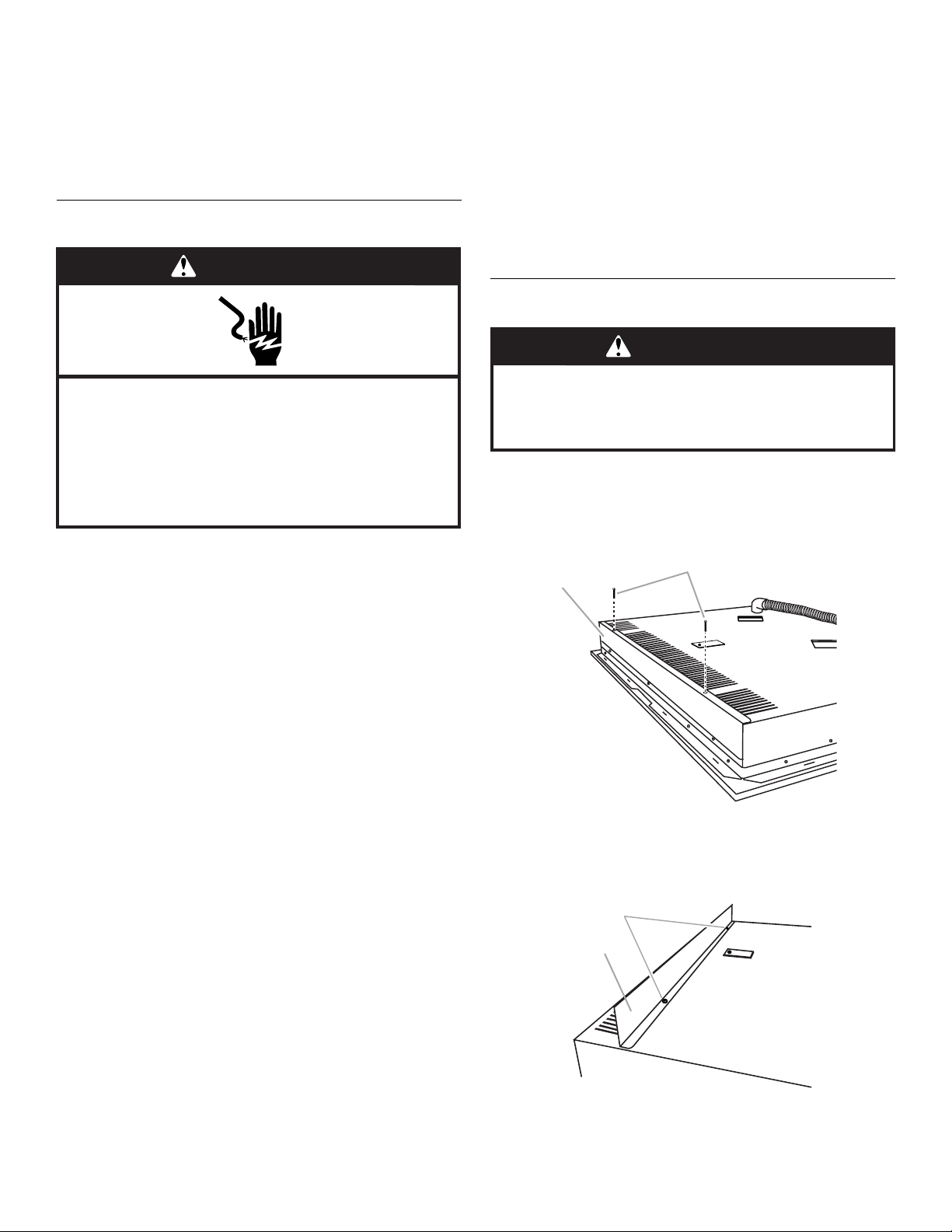
3. Remove the heat shield from the cooktop. Set the 2 screws
aside for reattaching the heat shield.
B
A
A. Heat shield
B. Remove screws
4. Using 2 screws, reattach the heat shield to the underside of
the cooktop at the predrilled holes as shown in the following
illustration.
B
A
A. Heat shield
B. Predrilled holes
3
Page 4

Install Foam Strip
C
A
B
1. Remove foam strip from literature packing.
2. Remove backing from foam strip.
3. Apply foam strip adhesive-side down around bottom of
cooktop, flush with edge.
NOTE: The foam strip protects the underside of the cooktop
glass from debris and helps the cooktop sit flat on uneven
counters.
A
B
Installing Brackets Before Placing Cooktop in Cutout
1. Position bracket to allow the clamping bracket to extend far
enough out from the cooktop for the installation of
2½" (6.4 cm) clamping screws. See “Attach Cooktop to
Countertop” for illustration of clamping screw installation.
B
A. Cooktop base
B. Foam strip
C. Glass
Install Cooktop
Style 1: Cooktop over undercounter built-in oven
IMPORTANT:
■ Your cooktop may not be approved for use over an
undercounter built-in oven. Contact your dealer to confirm
that your cooktop is approved for such use.
■ Clamping brackets should not be used.
1. Turn cooktop right side up.
2. Place cooktop in cutout.
NOTE: Make sure that the front edge of the cooktop is parallel
to the front edge of the countertop. If repositioning is needed,
lift entire cooktop up from cutout to avoid scratching the
countertop.
Style 2: Cooktop over cabinets
1. Determine whether your cabinet construction provides
clearance for installing clamping brackets at cooktop base
ends. This is the recommended location. Clamping brackets
can be installed on the back of cooktop base bottom, if
necessary.
A
C
A. Clamping bracket
B. Attachment screw and washer
C. Clamping screw
2. Rotate brackets so they do not extend beyond edge of
cooktop base.
3. Tighten screws enough to hold brackets in place when
cooktop is placed into the cutout.
4. Turn the cooktop right side up and place in cutout.
NOTE: Make sure that the front edge of the cooktop is parallel
to the front edge of the countertop. If repositioning is needed,
lift entire cooktop up from cutout to avoid scratching the
countertop.
5. Loosen the screws and rotate the brackets so that they are
perpendicular to the edge of the cooktop base and extend
beyond its edge. Securely tighten screws.
Installing Brackets After Placing Cooktop in Cutout
1. Place cooktop in cutout.
NOTE: Make sure that the front edge of the cooktop is parallel
to the front edge of the countertop. If repositioning is needed,
lift entire cooktop up from cutout to avoid scratching the
countertop.
2. Position clamping bracket to allow the bracket to extend far
enough out from the cooktop for the installation of
2½" (6.4 cm) clamping screws.
A
G
F
E
D
B
A. Attachment screw holes, side or back locations
B. Front of cooktop
2. The clamping brackets can be installed before or after the
cooktop is placed into the cutout. Complete the following
steps for the option you choose.
4
C
A. Glass cooktop
B. Cooktop base
C. Attachment screw
D. Clamping bracket (extends
far enough beyond cooktop
base to allow installation of
clamping screws)
E. 2½" (6.4 cm) clamping screw
(to be installed in “Attach
Cooktop to Countertop”
section)
F. C o un t e rt o p
G. Foam seal
3. Attach brackets to cooktop base bottom with bracket
attachment screws using the bracket mounting holes.
Securely tighten screws.
Page 5

Make Electrical Connection
H
WARNING
Electrical Shock Hazard
Disconnect power before servicing.
Use 8 gauge copper wire.
Electrically ground cooktop.
Failure to follow these instructions can result in death,
fire, or electrical shock.
This cooktop is manufactured with a frame-connected, green (or
bare) ground wire.
1. Disconnect power.
2. Remove junction box cover if it is present.
3. Connect the flexible cable conduit from the cooktop to the
junction box using a UL listed or CSA approved conduit
connector.
A
A. UL listed or CSA approved conduit connector
4. Tighten screws on conduit connector if present.
5. See “Electrical Connection Options Chart” to complete
installation for your type of electrical connection.
Electrical Connection Options Chart
If your home has: Go to Section:
4-Wire Cable from Home Power Supply
IMPORTANT: Use the 4-wire cable from home power supply in
the U.S. where local codes do not allow grounding through
neutral, New Branch circuit installations (1996 NEC), mobile
homes and recreational vehicles, new construction, and in
Canada.
A
B
C
D
A. Cable from home power
supply
B. Red wires
C. Green (or bare) ground wires
D. 3-Wire cable from cooktop
E. Junction box
F. White wire (from home
power supply)
G. UL listed wire connector
H. Black wires
I. UL listed or CSA approved
conduit connector with
wire bushing
1. Connect the 2 red wires (B) together using a UL listed wire
connector.
2. Connect the green (or bare) ground wire (C) from the cooktop
cable to the green (or bare) ground wire (in the junction box)
using a UL listed wire connector.
3. Put a UL listed wire connector on the end of the white wire (F).
NOTE: Do not connect the green (or bare) ground wire to the
neutral (white) wire in the junction box.
4. Connect the 2 black wires (H) together using a UL listed wire
connector.
5. Install junction box cover.
E
F
G
I
4-wire 4-Wire Cable from Home
Power Supply
½"
(1.3 cm)
3-wire 3-Wire Cable from Home
Power Supply
½"
(1.3 cm)
5
Page 6

3-Wire Cable from Home Power Supply - U.S. Only
IMPORTANT: Use the 3-wire cable from power supply where local
codes permit a 3-wire connection.
A
B
E
F
G
Attach Cooktop to Countertop
NOTE: This section applies only if you are using clamping
brackets.
D
C
B
A
H
C
I
D
A. Cable from home power supply
B. Red wires
C. Green (or bare) ground wire
from cooktop
D. 3-wire cable (from cooktop)
E. Junction box
F. White wire (from home
power supply)
G. UL listed wire connector
H. Black wires
I. UL listed or CSA approved
conduit connector with wire
bushing
1. Connect the 2 red wires (B) together using a UL listed wire
connector.
2. Connect the green (or bare) cooktop cable wire (C) to the
white (neutral) wire (F) in the junction box using a UL listed
wire connector.
3. Connect the 2 black wires (H) together using a UL listed wire
connector.
4. Install junction box cover.
A. Clamping screw
B. Countertop
C. Foam seal
D. Cooktop
1. Place the 2½" (6.4 cm) clamping screws into the brackets.
2. Check that the cooktop is level.
3. Use a flat-blade screwdriver to tighten the screws against the
countertop. Do not overtighten.
Complete Installation
1. Check that all parts are now installed. If there is an extra part,
go back through the steps to see which step was skipped.
2. Dispose of/recycle all packaging materials.
3. Use a mild solution of liquid household cleaner and warm
water to clean cooktop before use. Dry thoroughly with a soft
cloth. For more information, see the “Cooktop Care” section
of the Use and Care Guide.
4. Read “Cooktop Use” in the cooktop Use and Care Guide.
NOTE: If the cooktop does not work after turning on the power,
check that a circuit breaker has not tripped or a household fuse
has not blown. See “Troubleshooting” section in the Use and Care
Guide for further information.
If you need Assistance or Service:
Please reference the “Assistance or Service” section of the Use
and Care Guide or contact the dealer from whom you purchased
your cooktop
6
Page 7

SÉCURITÉ DE LA TABLE DE CUISSON
Votre sécurité et celle des autres est très importante.
Nous donnons de nombreux messages de sécurité importants dans ce manuel et sur votre appareil ménager. Assurez-vous de
toujours lire tous les messages de sécurité et de vous y conformer.
Voici le symbole d’alerte de sécurité.
Ce symbole d’alerte de sécurité vous signale les dangers potentiels de décès et de blessures graves à vous
et à d’autres.
Tous les messages de sécurité suivront le symbole d’alerte de sécurité et le mot “DANGER” ou
“AVERTISSEMENT”. Ces mots signifient :
Risque possible de décès ou de blessure grave si vous ne
DANGER
AVERTISSEMENT
Tous les messages de sécurité vous diront quel est le danger potentiel et vous disent comment réduire le risque de blessure et
ce qui peut se produire en cas de non-respect des instructions.
suivez pas immédiatement les instructions.
Risque possible de décès ou de blessure grave si vous
ne suivez pas les instructions.
INSTRUCTIONS D'INSTALLATION
Outillageet pièces
Rassembler les outils et pièces nécessaires avant de commencer
l'installation. Lire et suivre les instructions fournies avec les outils
indiqués ici.
Outils nécessaires
■ Mètre ruban
■ Tournevis à lame plate
■ Tournevis Phillips
■ Perceuse manuelle ou
électrique
■ Niveau
Pièces fournies
■ Brides de fixation (2)
■ Vis de fixation de 2½" (6,4 cm) (4) et rondelles (4)
■ Vis de tôlerie n° 8 x ³⁄₈" (9,5 mm) (4)
■ Écran thermique (fixé à la base de la table de cuisson pour le
transport)
Pièces nécessaires
■ Serre-câble (homologation UL ou CSA)
■ Connecteurs de fils (homologation UL)
Consulter les codes locaux. Vérifier l'alimentation électrique
existante. Voir “Spécifications électriques”.
Toutes les connexions électriques doivent être effectuées par un
électricien qualifié et certifié.
■ Marqueur ou crayon
■ Pince
■ Foret de ¼"
■ Scie sauteuse
Exigences d'emplacement
S'assurer d'avoir tout le nécessaire pour une installation
convenable. C'est à l'installateur qu'incombe la responsabilité de
se conformer aux dégagements de séparation spécifiés dans ces
instructions.
IMPORTANT : Observer les dispositions de tous les codes et
règlements en vigueur. Lors de l'installation de la table de cuisson,
utiliser les dimensions minimums indiquées.
■ Afin de supprimer le risque de brûlures ou d'incendie en se
penchant au-dessus des unités de surface chauffées, le
rangement en armoire au-dessus des unités de surface doit
être évité. Si le rangement en armoire est envisagé, le risque
peut être réduit par l'installation d'une hotte de cuisine
opérant horizontalement sur un minimum de 5" (12,7 cm) audelà du bas des armoires.
■ Vérifier que la base de la table de cuisson comporte une
étiquette d'installation approuvée. Vérifier les numéros de
modèles de four approuvés qui peuvent être installés avec
votre numéro de modèle de table de cuisson. Si vous ne
trouvez pas cette étiquette, il se peut que votre table de
cuisson ne soit pas approuvée pour une utilisation au-dessus
d'un four encastré sous comptoir. Contacter le marchand pour
confirmer que votre table de cuisson est bien approuvée.
7
Page 8

■ Les fours approuvés pour ce type d'installation comportent
une étiquette d'approbation située sur le dessus du four. Si
vous ne trouvez pas cette étiquette, contactez votre vendeur
pour confirmer que le four est bien approuvé. Consulter les
Instructions d'installation du fabricant du four pour obtenir
l'approbation de l'utilisation en encastrement et les
dimensions correctes.
■ Lors de l'installation de la table de cuisson sur un four
encastré sous comptoir, ne pas fixer la table de cuisson au
comptoir avec des brides, ni sceller la table de cuisson au
plan de travail. Ceci facilitera la dépose de la table de cuisson
plus tard en cas de besoin de réparation.
■ Utiliser les dimensions d'ouverture du plan de travail qui sont
indiquées dans ces Instructions d'installation. Les dimensions
données sont les espacements minimums et fournissent un
dégagement de 0" (0 cm).
■ Une source d'électricité avec liaison à la terre est nécessaire.
Voir la section “Spécifications électriques”.
Dimensions du placard
C
A
D
B
L
F
E
G
H
I
Dimensions du produit
A
A. 21⁹⁄₁₆" (54,6 cm)
B. 31" (78,7 cm) sur les modèles de 30" (76,2 cm)
37" (94 cm) sur les modèles de 36" (91,4 cm)
C. 3
³⁄₃₂
" (7,9 cm)
D. Plaque signalétique du numéro de modèle et
numéro de série (située sous la base de la table
de cuisson au coin droit avant)
K
J
B
C
D
A. 30" (76,2 cm) sur les modèles de 30" (76,2 cm)
36" (91,4 cm) sur les modèles de 36" (91,4 cm)
B. Zone de matière combustible au-dessus du plan de travail (espace
délimité par des lignes pointillées ci-dessus)
C. Distance de séparation de 30" (76,2 cm) ou plus entre le plan de
travail et le fond d'un placard métallique ou de bois non protégé
(distance de séparation de 24" [61 cm] ou plus si le fond du placard
de métal ou de bois est protégé par une plaque de ¼" (0,6 cm) ou
plus de matériau résistant aux flammes recouvert d'une feuille
métallique d'épaisseur égale ou supérieure à calibre 28 pour l'acier,
0,015" [0,04 cm] pour l'acier inoxydable, ou 0,024" [0,06 cm] pour
l'aluminium ou 0,020" [0,05 cm] pour le cuivre)
D. Profondeur recommandée des placards muraux 13" (33 cm)
E. 2" (5,1 cm)
F. 20½" (52 cm)
G. Distance de séparation de 18" (45,7 cm) ou plus entre placards
muraux et plan de travail avec distance minimale de séparation
horizontale pour la table de cuisson
H. Boîtier de connexion ou prise électrique; 12" (30,5 cm) ou plus
depuis le bas du plan de travail
I. Boîtier de connexion ou prise électrique; 10" (25,4 cm) depuis le
côté droit du placard
J. 29½" (74,9 cm) sur les modèles de 30" (76,2 cm)
35½" (90,2 cm) sur les modèles de 36" (91,4 cm)
K. Distance de séparation de 1" (2,5 cm) ou plus par rapport à la
surface de matériau combustible la plus proche, à gauche ou à
droite au-dessus de la table de cuisson
L. Distance de séparation de 1" (2,5 cm) ou plus entre la paroi arrière
et le plan de travail
REMARQUES : Après le découpage de l'ouverture dans le plan
de travail, dans certaines configurations d'installation il sera
nécessaire d'entailler les parois latérales du placard inférieur pour
le passage de la base de la table de cuisson. Pour éviter cette
modification, utiliser un placard inférieur dont la largeur des parois
latérales est supérieure à celle de l'ouverture découpée.
Si le placard comporte un tiroir, on devra ménager une distance
de séparation de 5¹⁄₈" (13 cm) ou plus entre le plan de travail et le
sommet du tiroir (ou autre obstruction) dans le placard inférieur.
En cas d'installation d'une hotte au-dessus de la table de cuisson,
suivre les instructions fournies avec la hotte concernant les
dimensions de dégagement à respecter au-dessus de la surface
de la table de cuisson.
8
Page 9

Spécifications électriques
AVERTISSEMENT
Risque de choc électrique
Déconnecter la source de courant électrique avant
d'entreprendre le travail.
Utiliser du fil de cuivre de calibre 8.
Relier la table de cuisson à la terre.
Le non-respect de ces instructions peut causer un
décès, un incendie ou un choc électrique.
Si on utilise un conducteur distinct de liaison à la terre lorsque les
codes le permettent, il est recommandé qu'un électricien qualifié
vérifie que la liaison à la terre et le calibre pour fils sont conformes
aux codes locaux.
Vérifier avec un électricien qualifié si vous avez des doutes quant
à la qualité de la liaison à la terre de la table de cuisson.
Il n’est pas recommandé d’installer un fusible dans le conducteur
neutre ou le conducteur de liaison à la terre.
S'assurer que la connexion électrique et le calibre des fils sont
appropriés et conformes à la norme National Electrical Code, aux
normes ANSI/NFPA 70 - dernière édition, ou aux normes CSA
C22.1-94, au Code canadien de l'électricité, Partie 1 et C22.2
N° O-M91 - dernière édition, et à tous les codes et règlements
locaux.
Pour obtenir un exemplaire de la norme des codes ci-dessus,
contacter :
National Fire Protection Association
One Batterymarch Park
Quincy, MA 02269
CSA International
8501 East Pleasant Valley Road
Cleveland, OH 44131-5575
Avant d'établir la connexion électrique :
Pour installer la table de cuisson correctement, il faut établir le
type de raccords électriques que l'on utilisera et suivre les
instructions indiquées ici.
■ L'appareil doit être alimenté par un circuit monophasé de
240 V CA seulement, 60 Hz à 4 fils ou 3 fils, sur un circuit
séparé de 50 ampères [modèles de 36" (91,4 cm)] ou de
40 ampères [modèles de 30" (76,2 cm)], fusionné aux deux
extrémités de la ligne.
■ La table de cuisson doit être raccordée directement au boîtier
de connexion par l'intermédiaire d'un câble flexible à
conducteur de cuivre (avec blindage ou gaine non métallique).
Le câble blindé flexible sortant du boîtier de distribution
(fusible ou disjoncteur) doit être raccordé directement au
boîtier de connexion.
■ Repérer le boîtier de connexion pour laisser le plus d'espace
possible entre celui-ci et la table de cuisson pour pouvoir
déplacer la table de cuisson en cas de besoin de réparation à
l'avenir.
■ Ne pas couper le conduit. La longueur du conduit fournie est
destinée à faciliter le fonctionnement de la table de cuisson.
■ Un connecteur de conduit homologué UL ou CSA doit être
fourni à chaque extrémité du câble d'alimentation électrique (à
la table de cuisson et au boîtier de connexion). Un connecteur
de conduit homologué est déjà fourni à la table de cuisson.
■ Si le domicile est équipé d'un câblage en aluminium, suivre les
instructions suivantes :
1. Connecter une section de câble en cuivre massif aux
conducteurs en queue de cochon.
2. Connecter le câblage en aluminium à la section ajoutée
de câblage en cuivre en utilisant des connecteurs et/ou
des outils spécialement conçus et homologués UL pour
fixer le cuivre à l'aluminium.
Appliquer la procédure recommandée par le fabricant des
connecteurs. La connexion aluminium/cuivre doit être
conforme aux codes locaux et aux pratiques de câblage
acceptées par l'industrie.
Installation del'écran thermique
AVERTISSEMENT
Risque du poids excessif
Utiliser deux ou plus de personnes pour déplacer et
installer la table de cuisson.
Le non-respect de cette instruction peut causer
une blessure au dos ou d'autre blessure.
1. Déterminer l'emplacement final de la table de cuisson.
2. À deux personnes ou plus, placer la table de cuisson à
l'envers sur une surface de travail protégée.
3. Retirer l'écran thermique de la table de cuisson. Placer les
2 vis de côté pour réinstaller l'écran thermique.
B
A
A. Écran thermique
B. Retirer les vis
4. À l'aide de 2 vis, réinstaller l'écran thermique sur la face
inférieure de la table de cuisson dans les trous prépercés : voir
l'illustration suivante.
B
A
A. Écran thermique
B. Trous prépercés
9
Page 10

Installation de la bande de mousse
C
A
B
1. Enlever la bande de mousse du sachet de documentation.
2. Retirer l'endos de la bande de mousse.
3. Appliquer le côté adhésif de la bande de mousse autour du
fond de la table de cuisson, en affleurement avec le rebord.
REMARQUE : La bande de mousse protège la face inférieure
du verre de la table de cuisson des débris et l'aide à reposer à
plat sur des plans de travail irréguliers.
A
B
Installation des brides avant de positionner la table de
cuisson dans l'ouverture
1. Positionner les brides de façon à ce qu'elles dépassent
suffisamment de la table de cuisson pour l'installation des vis
de fixation de 2½" (6,4 cm). Voir “Fixation de la table de
cuisson au plan de travail” pour avoir une illustration de
l'installation des vis de fixation.
A. Base de la table de cuisson
B. Bande de mousse
C. Verre
Installationde latable de cuisson
Style 1 : Table de cuisson sur four encastré sous
comptoir
IMPORTANT :
■ Votre table de cuisson peut ne pas être compatible pour
l'installation sur un four encastré sous comptoir. Contacter le
marchand pour confirmer que votre table de cuisson est bien
approuvée.
■ Ne pas utiliser de brides de fixation.
1. Tourner le côté droit de la table de cuisson vers le haut.
2. Placer la table de cuisson dans l'ouverture.
REMARQUE : S'assurer que le bord avant de la table de
cuisson est parallèle au bord avant du plan de travail. S'il est
nécessaire de repositionner la table de cuisson, la soulever
entièrement de l'ouverture pour éviter de rayer le plan de
travail.
Style 2 : Table de cuisson sur placards
1. Déterminer si l'installation des placards permet le
dégagement nécessaire pour l'installation de brides de
fixation aux extrémités de la base de la table de cuisson. Il
s'agit de l'emplacement recommandé. Des brides de fixation
peuvent être installées à l'arrière de la partie inférieure de la
base de la table de cuisson, si nécessaire.
A
B
C
A. Bride de fixation
B. Vis de fixation et rondelle
C. Vis de fixation
2. Faire tourner les brides de façon à ce qu'elles ne dépassent
pas du bord de la base de la table de cuisson.
3. Serrer les vis suffisamment pour maintenir les brides en place
lorsque la table de cuisson est positionnée dans l'ouverture.
4. Tourner la table de cuisson, côté droit vers le haut, et la
positionner dans l'ouverture.
REMARQUE : S'assurer que le bord avant de la table de
cuisson est parallèle au bord avant du plan de travail. S'il est
nécessaire de repositionner la table de cuisson, la soulever
entièrement de l'ouverture pour éviter de rayer le plan de
travail.
5. Desserrer les vis et faire tourner les brides pour qu'elles soient
perpendiculaires au bord de la base de la table de cuisson et
qu'elles dépassent de son bord. Bien serrer les vis.
Installation des brides après avoir positionné la table de
cuisson dans l'ouverture
1. Placer la table de cuisson dans l'ouverture.
REMARQUE : S'assurer que le bord avant de la table de
cuisson est parallèle au bord avant du plan de travail. S'il est
nécessaire de repositionner la table de cuisson, la soulever
entièrement de l'ouverture pour éviter de rayer le plan de
travail.
2. Positionner les brides de façon à ce qu'elles dépassent
suffisamment de la table de cuisson pour l'installation des vis
de fixation de 2½" (6,4 cm)
.
A
B
A. Trous des vis de fixation, emplacements latéraux
ou arrière
B. Avant de la table de cuisson
2. Les brides de fixation peuvent être installées avant ou après le
positionnement de la table de cuisson dans l'ouverture.
Procéder aux étapes suivantes selon l'option choisie.
10
G
F
E
D
A. Table de cuisson en verre
B. Base de la table de cuisson
C. Vis de fixation
D. Bride de fixation (dépassant
suffisamment de la base de
la table de cuisson pour
permettre l'installation des
vis de fixation)
C
E. Vis de fixation de 2½" (6,4 cm)
(à installer à la section
“Fixation de la table de
cuisson au plan de travail”)
F. Plan de travail
G. Joint de mousse
Page 11

3. Fixer les brides à la partie inférieure de la base de la table de
H
cuisson à l'aide des vis de fixation en utilisant les trous de
montage des brides. Bien serrer les vis.
Câble à 4 conducteurs depuis le point de distribution du
domicile
Raccordement électrique
AVERTISSEMENT
Risque de choc électrique
Déconnecter la source de courant électrique avant
d'entreprendre le travail.
Utiliser du fil de cuivre de calibre 8.
Relier la table de cuisson à la terre.
Le non-respect de ces instructions peut causer un
décès, un incendie ou un choc électrique.
Un conducteur vert (ou nu) de liaison à la terre est connecté au
châssis de la table de cuisson lors de la fabrication.
1. Déconnecter la source de courant électrique.
2. Le cas échéant, enlever le couvercle du boîtier de connexion.
3. Avec le connecteur de conduit (homologation UL ou CSA),
connecter le conduit de câble flexible de la table de cuisson
au boîtier de connexion.
IMPORTANT : Utiliser le câble à 4 conducteurs provenant du
point de distribution du domicile aux États-Unis lorsque les codes
ne permettent pas la mise à la terre par l'intermédiaire du
conducteur neutre, en cas de nouvelle installation avec
alimentation par un circuit secondaire (1996 NEC), dans les
résidences mobiles et les véhicules récréatifs, dans les nouvelles
constructions, et au Canada.
A
B
E
F
G
C
D
A. Câble depuis le point de
distribution du domicile
B. Conducteurs rouges
C. Conducteurs verts (ou nus) de
liaison à la terre
D. Câble à 3 conducteurs depuis
la table de cuisson
E. Boîtier de connexion
F. Conducteur blanc (depuis le
point de distribution du
domicile)
G. Connecteur de fils
(homologation UL)
H. Conducteurs noirs
I. Connecteur de conduit
(homologation UL ou CSA)
avec passe-fils
I
A
A. Connecteur de conduit
(homologation UL ou CSA)
4. Serrer les vis du connecteur de conduit, le cas échéant.
5. Voir “Tableau des options de raccordement électrique” pour
terminer l'installation correspondant à votre type de
raccordement électrique.
Tableau des options de raccordement électrique
Câblage de la maison : Voir la section suivante :
4 conducteurs Câble à 4 conducteurs depuis
½"
(1,3 cm)
3 conducteurs Câble à 3 conducteurs depuis
le point de distribution du
domicile
le point de distribution du
domicile
1. Connecter ensemble les 2 conducteurs rouges (B) avec un
connecteur de fils (homologation UL).
2. Connecter le conducteur vert (ou nu) de liaison à la terre (C) du
câble de la table de cuisson au conducteur vert (ou nu) de
liaison à la terre dans le boîtier de connexion - utiliser un
connecteur de fils (homologation UL).
3. Placer un connecteur de fils (homologation UL) à l'extrémité
du conducteur blanc (F).
REMARQUE : Ne pas connecter le conducteur vert (ou nu) de
liaison à la terre au conducteur neutre (blanc) dans le boîtier
de connexion.
4. Connecter ensemble les 2 conducteurs noirs (H) avec un
connecteur de fils (homologation UL).
5. Installer le couvercle du boîtier de connexion.
½"
(1,3 cm)
11
Page 12

Câble à 3 conducteurs depuis le point de distribution du
domicile - É.-U. seulement
IMPORTANT : Utiliser le câble à 3 conducteurs depuis le point de
distribution du domicile lorsque les codes locaux autorisent un tel
raccordement.
A
B
E
F
G
Fixationde la table de cuisson au plande
travail
REMARQUE : Cette section s'applique uniquement en cas
d'utilisation de brides de fixation.
D
C
B
A
H
C
I
D
A. Câble depuis le point de
distribution du domicile
B. Conducteurs rouges
C. Câble vert ou nu depuis la
table de cuisson
D. Câble à 3 conducteurs
(depuis la table de cuisson)
E. Boîtier de connexion
F. Conducteur blanc (depuis le
point de distribution du
domicile)
G. Connecteur de fils
(homologation UL)
H. Conducteurs noirs
I. Connecteur de conduit
(homologation UL ou CSA)
avec passe-fils
1. Connecter ensemble les 2 conducteurs rouges (B) avec un
connecteur de fils (homologation UL).
2. Connecter le conducteur vert ou nu de la table de cuisson (C)
au conducteur blanc (neutre) (F) dans le boîtier de connexion
avec un connecteur de fils (homologation UL).
3. Connecter ensemble les 2 conducteurs noirs (H) avec un
connecteur de fils (homologation UL).
4. Installer le couvercle du boîtier de connexion.
A. Vis de fixation
B. Plan de travail
C. Joint en mousse
D. Table de cuisson
1. Placer les vis de fixation de 2½" (6,4 cm) dans les brides.
2. Vérifier que la table de cuisson est d'aplomb.
3. À l'aide d'un tournevis à lame plate, serrer les vis sur le plan
de travail. Ne pas serrer excessivement.
Achever l'installation
1. Vérifier que toutes les pièces sont maintenant installées. S'il
reste une pièce, passer en revue les différentes étapes pour
découvrir laquelle aurait été oubliée.
2. Jeter/recycler tous les matériaux d'emballage.
3. Utiliser une solution d'eau tiède et de nettoyant ménager
liquide doux pour nettoyer la table de cuisson avant utilisation.
Sécher parfaitement avec un linge doux. Pour plus de
renseignements, voir la section “Entretien de la table de
cuisson” du Guide d'utilisation et d'entretien.
4. Lire “Utilisation de la table de cuisson” dans le Guide
d'utilisation et d'entretien de la table de cuisson.
REMARQUE : Si la table de cuisson ne fonctionne pas une fois
l'alimentation branchée, vérifier que le disjoncteur n'est pas
déclenché ou que les fusibles ne sont pas grillés. Voir la section
“Dépannage” dans le Guide d'utilisation et d'entretien pour plus
de renseignements.
W10098720
© 2006.
All rights reserved.
Tous droits réservés.
Si vous avez besoin d'assistance ou de service :
Consulter la section “Assistance ou service” du Guide d'utilisation
et d'entretien ou contacter le marchand chez qui vous avez
acheté votre table de cuisson.
Printed in Spain.
Imprimé en Espagne
12/06
 Loading...