

Page 1
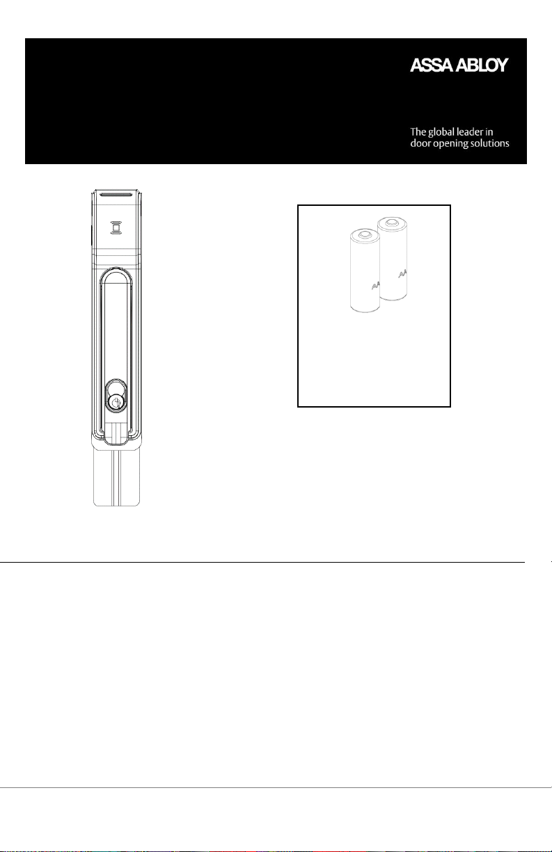
AA Lithium Batteries
required. Use of other
types of batteries, such as
alkaline, will significantly
decrease battery life.
2x
*All battery life claims are approximate and based on a set
configuration profile. Battery performance is based on predefined system settings such as battery chemistry and battery
model used, credential presentation settings (LED/buzzer), UHF
polling period, UHF status intervals, and operations per
day. Actual battery performance will vary and depends on the
factors above.
HES KS100 Aperio
Wireless Cabinet Lock
Installation and Operating Instructions
Product Specifications
Wireless Frequency: 2.4GHz, IEEE 802.15.4, using AES 128-bit encryption
Lock Battery Type: AA Lithium, 1.5 Volts (V)
Battery Life: 50,000 cycles*
Holding Force: 400 lbs
FCC Part 15 Compliant, Industry Canada Compliant
Operating Temperature: 32 to 122 F (0 to 50 C)
HID® multiCLASS SE® technology Credentials Supported: High Frequency (13.56 MHz) – HID iCLASS,
HID iClass SE (SIO-enabled), HID iCLASS Seos, HID MIFARE SE, HID DESfire EV1 SE, MIFARE
CLASSIC DESfire EV1. Low Frequency (125KHz) – HID Prox, AWID, EM4102, ioProx. NFC/BLE Enabled
Mobile Phones.
Page 1 of 14
For more information visit website assaabloyesh.com P/N: 3080006.017_1
Page 2
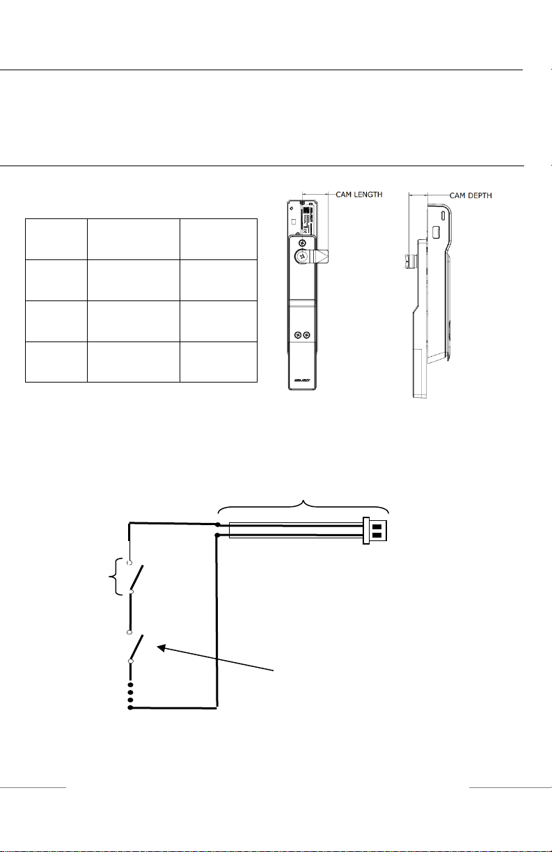
CAM
CAM LENGTH
CAM
DEPTH
38mm - 4
(Standard)
38mm [1-1/2"]
26mm [1”]
38mm - 5
(Optional)
38mm [1-1/2”]
28mm
[1-1/10"]
45 mm - 1
(Optional)
45mm
[1-3/4”]
18mm
[7/10”]
For Technical Support Please call 1-800-810-WIRE
DPS Extension Cable
DPS
Switch #1
(SPST-NO):
Extending the DPS Circuit:
A: Remove the DPS jumper
B: Connect the included DPS extension
cable
C: Connect additional normally open
DPS switches as shown to monitor
additional panels.
Recommended tools
Cutting Wheel
Phillips #2 Screwdriver
Hardware Specifications
Table 1 – Cam
DPS Cable Extension
Optional – The DPS signal is closed when the handle is resting in its locked position. The DPS circuit can be
extended to include normally open DPS switches arranged in a series to monitor additional doors and panels
Provided
Switches
(SPST-NO):
As Needed
Optional
Page 2 of 14
For more information visit website assaabloyesh.com P/N: 3080006.017_1
Page 3
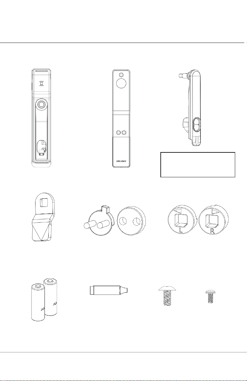
Lock Body
Battery Bracket
Handle Assembly
Handing Selectors
SFIC Cam and
Spacer
Cam
2x AA Lithium
Batteries
Screw A
#1/4-20 x .50
Truss Head
Phillips
3x Screw B
8/32 x 5/16”
Pan Head
Phillips
Optional External DPS Cable
Harness
3x Dolphin
Connector
Note: SFIC mechanical key
override/SFIC blank sold
separately.
Package Contents
Page 3 of 14
For more information visit website assaabloyesh.com P/N: 3080006.017_1
Page 4
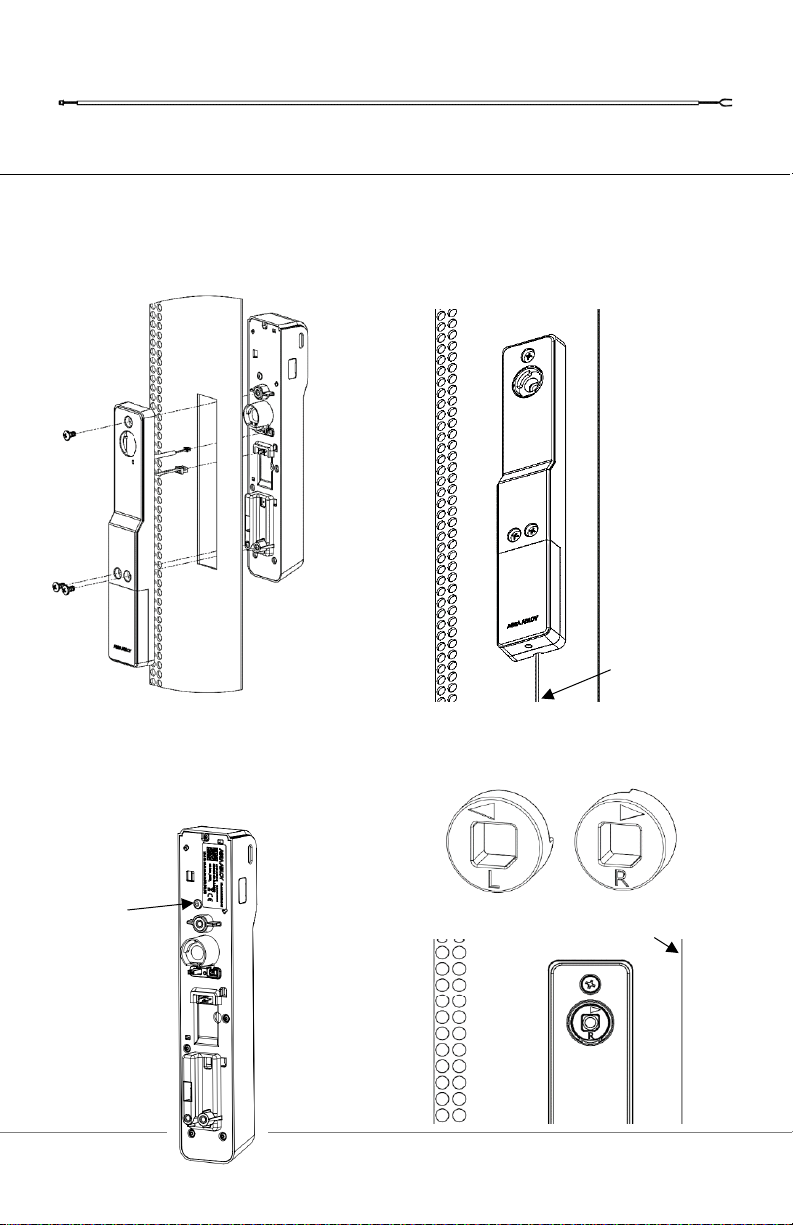
1. Locate the 150mm x 25mm lock cutout on the door. Connect battery cable and
optional DPS cable to lock body. Secure battery bracket to lockbody using 3x screw
B.
2. Ensure lock body is flush against the
mounting surface to depress tamper
switch.
3. Select appropriate handing selector.
Tamper
Switch
Door Edge
DPS Cable
(optional)
Installing the Lock
Page 4 of 14
For more information visit website assaabloyesh.com P/N: 3080006.017_1
Page 5
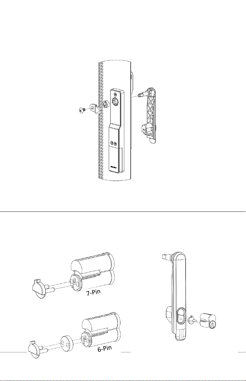
4. Install handle, handing selector, and cam. Secure with screw A.
1. Insert SFIC core and cam into handle. Use spacer for 6 pin SFIC core.
Note: ensure that the arrow on the
handing selector is pointing towards
the edge of the door.
Note: SFIC blank plastic core (SFIC-BC)
sold separately. SFIC Blank is required if
no cylinder Is used.
Installing the SFIC Core (Optional)
Page 5 of 14
For more information visit website assaabloyesh.com P/N: 3080006.017_1
Page 6
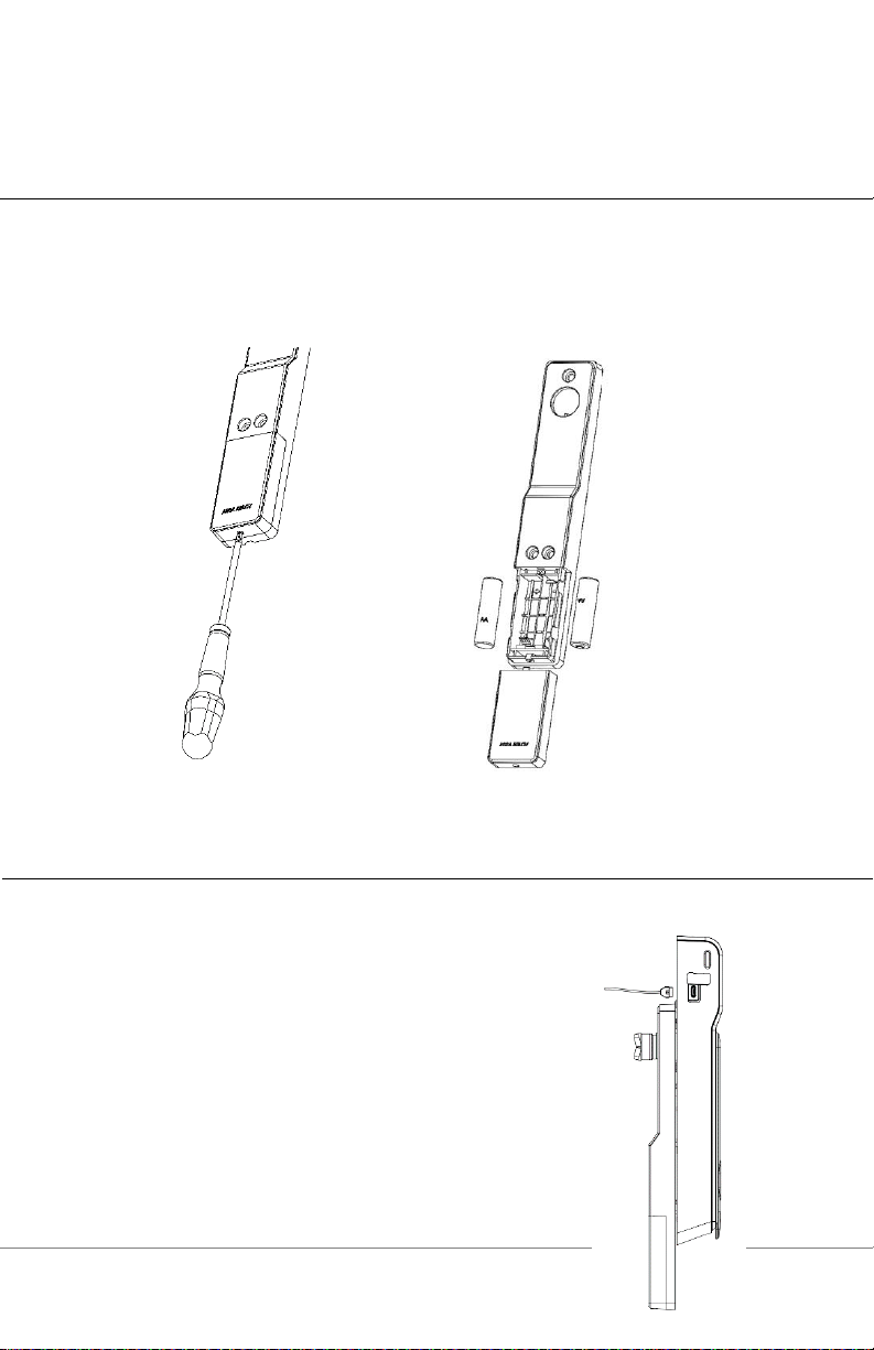
1. Loosen screw on battery cover, slide cover down, and install batteries in the
appropriate orientation.
For emergency power & local (hard wired) firmware
updates, use micro USB port located on the side of
the KS100 reader.
Installing the Batteries
Micro USB Port
Page 6 of 14
For more information visit website assaabloyesh.com P/N: 3080006.017_1
Page 7

Part Number
Description
SFIC
MEDECO X4 7-pin SFIC cylinder & 2 keys
(1 Control,1 User)
SFIC-BC
KS SFIC blank, black plastic core
KS-DPS
Surface mount DPS (external)
KS-CAM38
CAM: 38MM - 5 (28mm Depth)
KS-CAM45
CAM: 45MM - 1 (18mm Depth)
AH20W14
ASSA ABLOY Aperio™ AH20 1:1 Wiegand Hub
EXT-10-ANT
ASSA ABLOY Aperio™ Hub External Antenna - 3,9
dBi Omnidirectional
APA-10-PC
ASSA ABLOY Aperio™ Programming Kit
APD-10-USB
ASSA ABLOY Aperio™ USB Radio Dongle
Optional Accessories
Page 7 of 14
For more information visit website assaabloyesh.com P/N: 3080006.017_1
Page 8

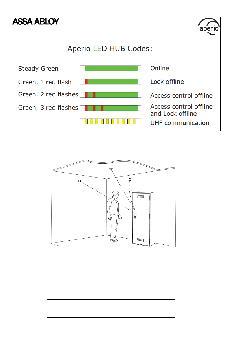
LED Codes
Page 8 of 14
For more information visit website assaabloyesh.com P/N: 3080006.017_1
Page 9
Technical Data - AH20
Approvals
CE, ETL, FCC, IC, C-Tick
Safety and emissions
FCC 47CFR Part 15 subpart
B and subpart C; IC RSS-210
EN ETSI 301 489-17 v2.1.1;
ENETSI 300 328 v1.7.1;
EN 60950-1 ed.2 2007
Dimensions (mm)
82x82x37
Power Supply
8-24 VDC
Current
250 mA minimum
Internal Antenna
2cross polarized dipoles
Aperio Hub
Page 9 of 14
For more information visit website assaabloyesh.com P/N: 3080006.017_1
Page 10

External Antenna
(Part No. EXT-10-ANT)
One reverse polarity SMA external
antenna connector.
Optional antenna type dipole with
max antenna gain of 3.9dBi
Radio Standard
IEEE 802.15.4(2.4GHz) -
15 channels (11-25)
Encryption (Radio
Communications)
AES 128 bits
Wireless Operating
Range
Up to 50 ft
Receiver Sensitivity
100dBm 20%PER
Wireless Transmit
Power
10 dBm/MHz
Class of Protection
IP 20
Operating temperature
5°C to 35°C
Humidity
< 95% non-condensing
Status
LED (red/green/orange)
Connect the Wiegand D1, D0, red, and green LED signals.
Connecting the Hub
The following applies only to Aperio factory paired kits with AH20 Hubs.
Page 10 of 14
For more information visit website assaabloyesh.com P/N: 3080006.017_1
Page 11

Note: The Green LED input is used to grant access to the cabinet lock. If the Green LED
signal is not available to indicate approved access, the approval input can be
activated by a relay with “NO” attached to Green LED and “C” to GND.
The Red LED input is used to indicate access denied. If the RED LED signal is
not connected, the lock will flash RED three times when a non-approved card is
presented indicating loss of connection to the hub rather than access denied. Any
other codes may be reference on the LED reference card.
WARNING
FCC Statement
This equipment has been tested and found to comply with the limits for a class B digital device, pursuant to part
15 of the FCC Rules. These limits are designed to provide reasonable protection against harmful interference in
a residential installation. This equipment generates, uses, and can radiate radio frequency energy and if not
installed and used in accordance with the instructions, may cause harmful interference to radio communications.
However, there is no guarantee that interference will not occur in a particular installation. If this equipment does
cause harmful interference to radio or television reception, which can be determined by turning the equipment off
and on, the user is encouraged to try to correct the interference by one or more of the following measures:
1. Reorient or relocate the receiving antenna.
2. Increase the separation between the equipment and receiver.
3. Connect the equipment into an outlet on a circuit different from that to which the receiver is connected.
4. Consult the dealer or an experienced radio/TV technician for help.
Operation with non-approved equipment is likely to result in interference to radio and TV reception. The user is
cautioned that changes and modifications made to the equipment without the approval of manufacturer could void
the user’s authority to operate this equipment.
Operation is subject to the following two conditions:
(1) this device may not cause interference, and
(2) this device must accept any interference, including interference that may cause undesired operation.
To comply with FCC and Industry Canada RF radiation exposure limits for general population, the module must
Page 11 of 14
For more information visit website assaabloyesh.com P/N: 3080006.017_1
Page 12

be installed to provide a separation distance of at least 20cm from all persons and must not be co-located or
operating in conjunction with any other antenna or transmitter.
This module is labeled with its own FCC ID and IC Certification Number. If the FCC ID and IC Certification
Number are not visible when the module is installed inside another device, then the outside of the device into
which the module is installed must also display a label referring to the enclosed module. In that case, the final
end product must be labeled in a visible area with the following:
Contains FCC ID: VC3-R100V3
Contains IC: 7160A-R100V3
IC Statement
This device complies with Industry Canada license-exempt RSS standards(s).
Operation is subject to the following two conditions:
(1) this device may not cause interference, and
(2) this device must accept any interference, including interference that may cause undesired operation.
Conformité aux normes FCC
Cet équipement a été testé et trouvé conforme aux limites pour un dispositif numérique de classe B, conformément
à la Partie 15 des règlements de la FCC. Ces limites sont conçues pour fournir une protection raisonnable contre
les interférences nuisibles dans une installation résidentielle. Cet équipement génère, utilise et peut émettre des
fréquences radio et, s'il n'est pas installé et utilisé conformément ment aux instructions du fabricant, peut causer
des interferences nuisibles aux communications radio. Rien ne garantit cependant que l'interférence ne se produira
pas dans une installation particulière. Si cet équipement provoque des interférences nuisibles à la réception radio
ou de télévision, qui peut être déterminé en comparant et en l'éteignant, l'utilisateur est encouragé à essayer de
corriger les interférence par une ou plusieurs des mesures suivantes:
1. Réorienter ou déplacer l'antenne de réception.
2. Augmenter la distance entre l'équipement et le récepteur.
3. Branchez l'appareil dans une prise sur un circuit différent de celui auquel le récepteur est connecté.
4. Consultez votre revendeur ou un technicien radio / TV pour assistance.Avertissement
Les changements ou modififications à cet appareil sans expressément approuvée par la partie responsable de
conformité pourraient annuler l'autorité de l'utilisateur de faire fonctionner cet équipement.
L'opération est soumise aux deux conditions suivantes:
(1) Cet appareil ne doit pas causer d'interférences nuisibles, et
(2) Cet appareil doit accepter toute interférence reçue, y compris les interférences susceptibles de provoquer un
fonctionnement indésirable.
Pour se conformer aux limites d'exposition aux rayonnements RF de la FCC et d'Industrie Canada pour la
population en général, le module doit être installé pour fournir une distance de séparation d'au moins 20 cm de
toutes les personnes et ne doit pas être localisé ou en combinaison avec une autre antenne ou émetteur.
Ce module est étiqueté avec son ID FCC et son numéro de certification IC. Si l'identifiant FCC et le numéro de
certification IC ne sont pas visibles lorsque le module est installé à l'intérieur d'un autre appareil, l'extérieur de
Page 12 of 14
For more information visit website assaabloyesh.com P/N: 3080006.017_1
Page 13

l'appareil dans lequel le module est installé doit également afficher une étiquette faisant référence au module cijoint. Dans ce cas, le produit final final doit être étiqueté dans une zone visible avec ce qui suit:
Contient FCC ID: VC3-R100V3
Contient IC ID:7160A-R100V3
Conformité aux normes IC
Cet appareil est confrome avec Industrie Canada exempt de license RSS standard(s).
Son fonctionnement est souimes aux deux conditions suivantes:
(1) cet appareil ne peut causer d’interférences, et
(2) cet appareil doit accepter toute interference, y compris des interférences qui peuvent provoquer un
fonctionnement indésirable du périphérique.
Page 13 of 14
For more information visit website assaabloyesh.com P/N: 3080006.017_1
Page 14

Page 14 of 14
For more information visit website assaabloyesh.com P/N: 3080006.017_1
 Loading...