

Page 1
K100-620 Aperio
Cabinet Lock Series
Installation Instructions
HES, Inc.
Phoenix, AZ
1.800.626.7590
www.hesinnovations.com
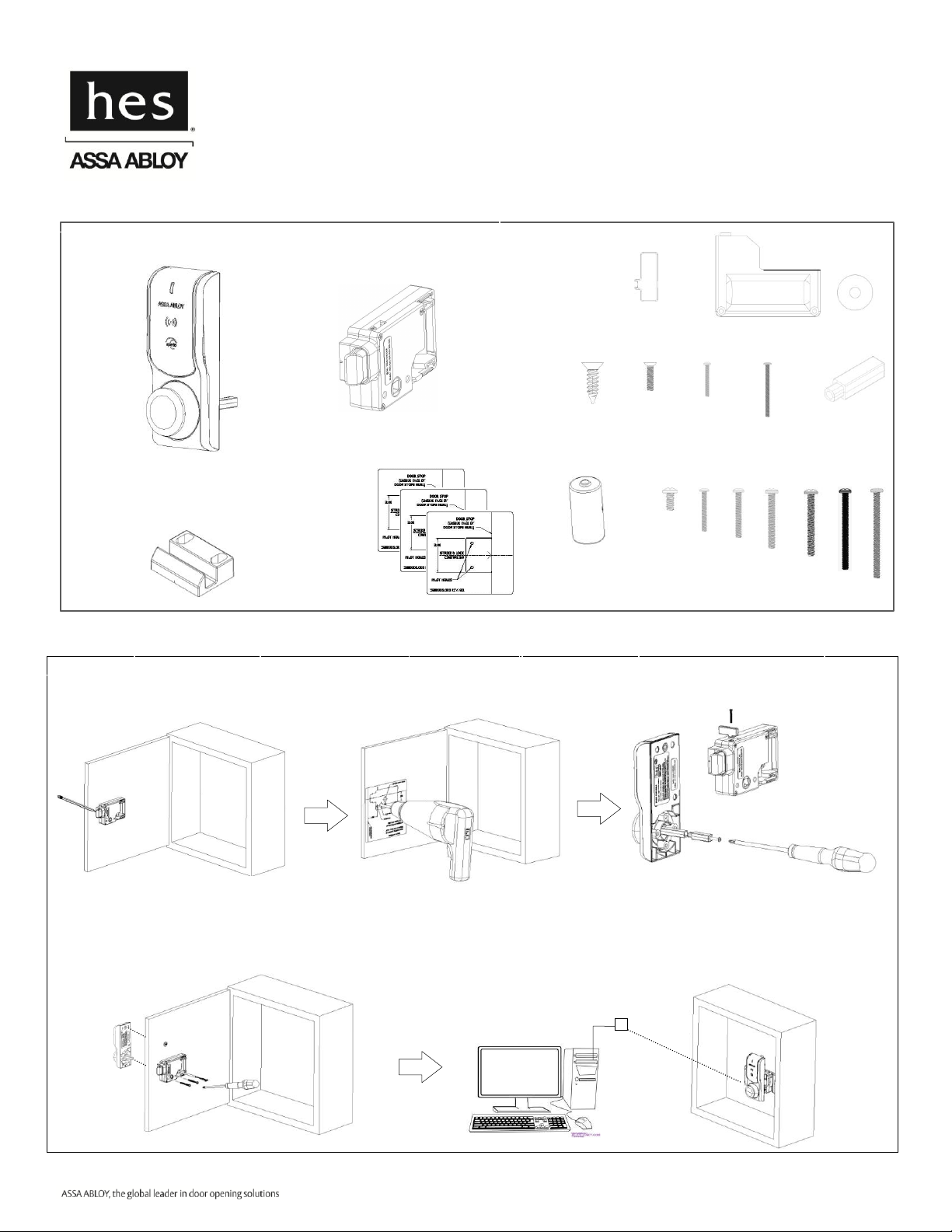
Machine
screw with
washer
Card Reader Template
Installation Hardware
Strike Plate
Antenna/Reader
6-32 screws
2X
5/16”
1”
1-5/8”
1-1/4”
1-3/4”
2-1/2”
2X
1X
1X
2X
2X
Shaft Extension
Battery Cover
Washer
0-80x½”
2-56x3/8”
2-56x1-1/4”
Battery
Key Override Paddle
1X
1X
1X
1X
2X
1X
1X
1X
Mounting
Templates
1X
1X
1X
6 x 1/2”
3X
Aperio Cabinet Lock Components
Quick Installation Summary
Lock
Body
5. Connect
2. Drill
3. Configure
1. Mark
4. Install
Aperio Hub
1-7/8”
2X
Part Number 3080006.001, Rev. D ©2012, HES, Inc. 1
Page 2
Installation Details
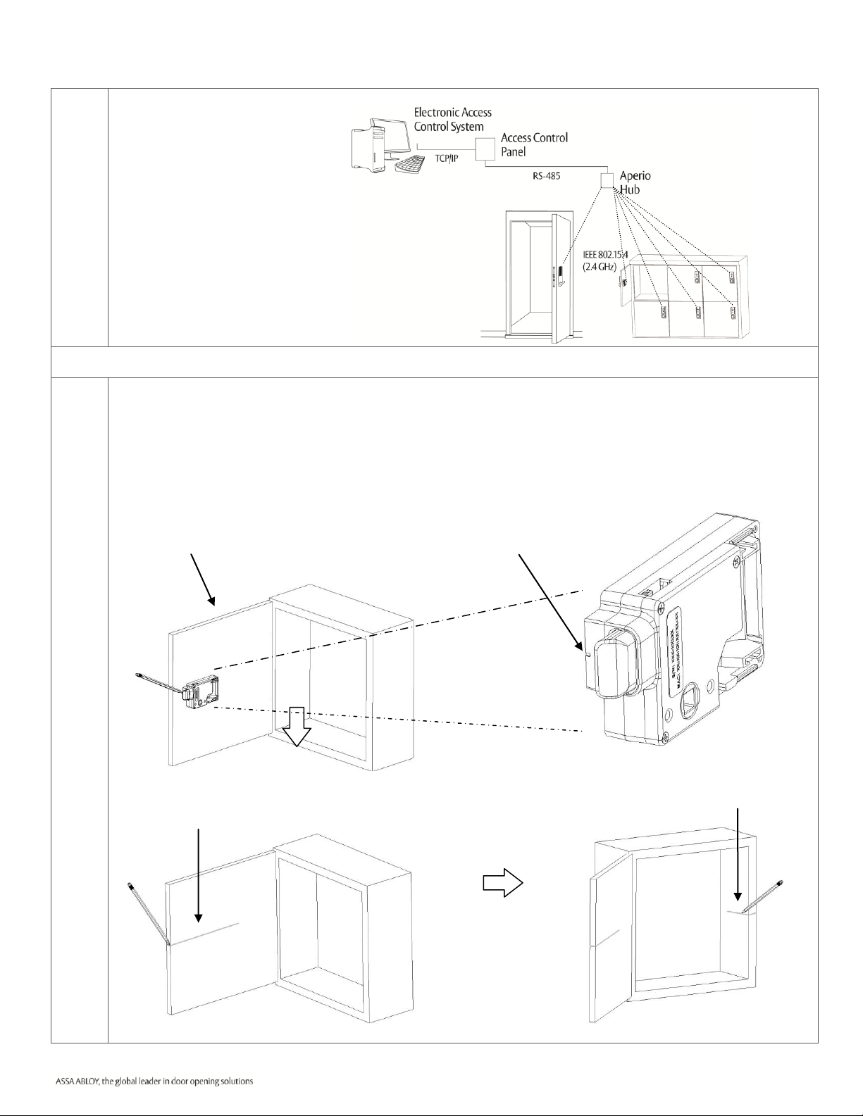
1
Before You Begin.
For a stable and reliable radio
link, make sure the locker,
drawer or cabinet on which you
are installing the K100 is
within fifty (50) feet of an
Aperio hub. (For details on
installing an Aperio Hub,
please refer to the Aperio Hub
Installation Instructions.)
Mark
2
Establish the horizontal centerline of the latch.
2a. Hold the lock body to the inside of the door and position it generally where you would like it to
mount. Locate lock centerline notch on the latch and use a pencil to mark this point on the inside of
the cabinet door.
2b. Draw the horizontal latch centerline from this mark on the inside of the cabinet door.
2c. Next, transfer this centerline to the inside of the cabinet or the second door on a
double-door cabinet.
2b. Draw latch centerline
2c. Transfer latch centerline
2a. Mark cabinet at centerline notch
Latch centerline notch
Part Number 3080006.001, Rev. D ©2012, HES, Inc. 2
Page 3
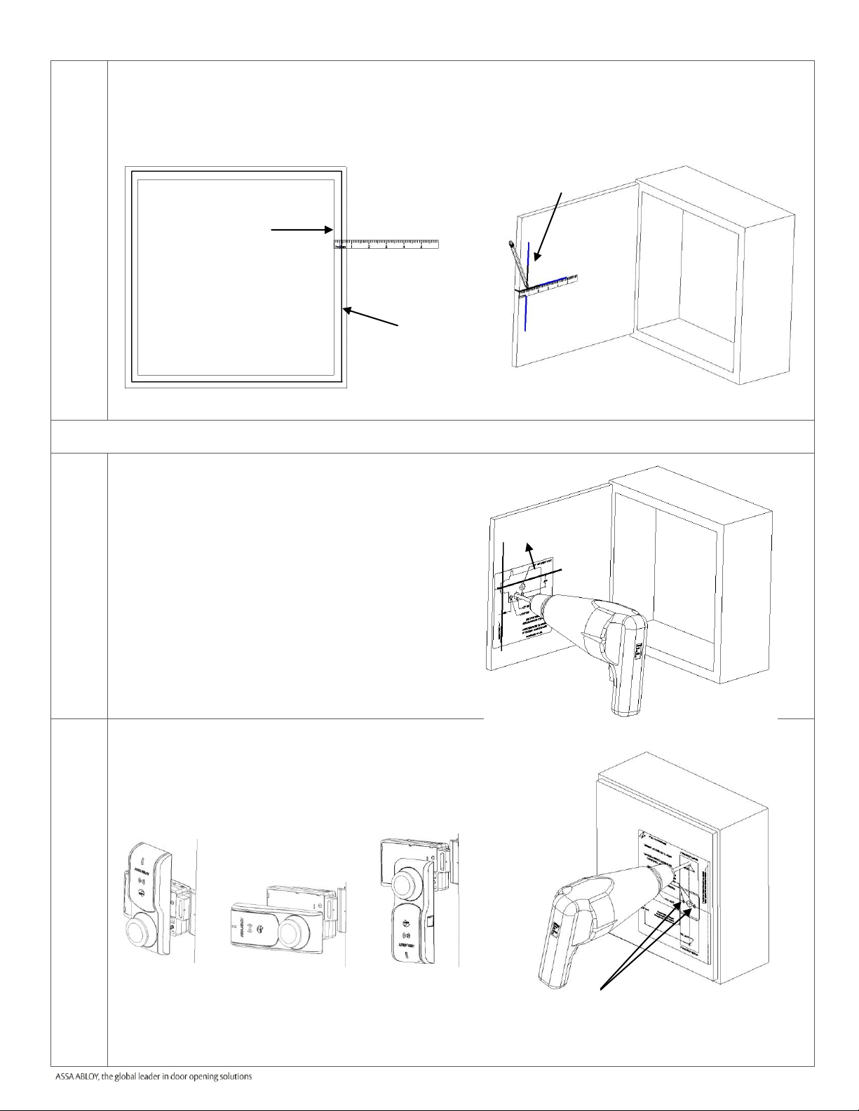
3
Transfer the location of the inside wall of the cabinet to the door.
3a. Measure the horizontal distance between the inside edge of the cabinet and the door edge.
3b. Using the same distance away from the door edge, draw a line on the inside surface of the door.
This line depicts the location of the strike mounting surface.
Drill
4
Place and use the Lock Template.
4a. Peel off the protective layer of the Lock Template
and align to both the latch centerline and the line
depicting the inside wall of cabinet. Press to secure.
4b. Drill four holes through the cabinet, as shown. Two
holes are 5/32” diameter and two are 1/2”
diameter.
4c. Remove the lock template from the door.
5
Place and use the Reader Template.
5a. Peel off the protective layer of the Reader Template
and align it to both holes drilled in the previous step.
5b. Drill only one 5/32” hole depending on the desired
antenna/reader orientations (see below).
5c. Remove the Reader Template from the door.
NOTE: Some antenna/reader orientations may prevent use of the key
override function. For example, in the door handing shown here,
manual override cannot be used in orientation “A”, but it can be
used in orientations “B” and “C”.
3a. Cabinet/door front view
3.b
4a. Align and place template.
4b. Drill.
5a. Align template to existing holes.
5b. Drill only one hole of the three
possible antenna/reader orientations
A
B
C
Door edge
Measure the
distance from
the inside edge
of the cabinet
to the edge of
the door.
3b. Draw a line on the door that depicts the
location of the inside edge of the cabinet
Mark the location of the
inside wall of the cabinet
to the door.
A B C
Part Number 3080006.001, Rev. D ©2012, HES, Inc. 3
Page 4

Configure
6
Install the Shaft Extension.
If your cabinet door thickness is greater
than ½”, install the Shaft Extension to the
Antenna/Reader to ensure proper
engagement into the lock. Install the Shaft
Extension to the shaft as shown here and
firmly tighten the screw.
Door Thickness
Extension
Shaft Used?
1/16” – ½”
NO
> ½” – 1 ½”
YES
7
Install the Key Override Paddle.
If a Key Override is used, install
the Key Override Paddle on the
arm of the lock body as shown
here and firmly tighten the
screw.
8
Key Override Door
Preparation.
If a Key Override is used, drill a hole in
the door based on cam length (R).
8a. Measure cam length (R).
8b. Calculate the distance from the lock
features based on the image to the
right.
8c. Drill a hole in the door based on the
cam lock installation instructions.
Shaft Extension
2-56 X 1-¼ screw
(provided)
0-80 X 1/2 screw (provided)
Table 1
Latch centerline
Drill hole in door
based on cam lock
installation
Key Override
Paddle
Part Number 3080006.001, Rev. D ©2012, HES, Inc. 4
Page 5

Install
9
Install the antenna/reader.
9a. Place and hold the antenna/reader to
the outside of cabinet, routing the
wire through the 1/2” offset hole.
9b. Install the washer and top screw,
which attach the antenna/reader to
the outside case.
Refer to the table below to determine
the length of the top mount screw
needed, based on the thickness
of the cabinet door.
WARNING!
Make sure you avoid crimping the
wires. Crimped wires may prevent the
Reader and Lock from functioning.
Table 2.
10
Install the lock.
10a. Remove the battery cover from lock. Place the lock on the inside of the door, threading the cable
through the lock.
10b. Using two 6-32 lock mount screws (see table 2 for length), attach the lock to the antenna/reader.
Tighten the screws.
Reader mounting.
Washer and screw.
9a.
9b.
Thread the cable
through the hole
in the lock.
10a. Place the lock and thread cable.
10b. Attach the lock to the antenna reader.
Table 2
Part Number 3080006.001, Rev. D ©2012, HES, Inc. 5
Page 6

11
Electrically connect the
antenna/reader wire to the lock
body.
Make sure to correctly orient connector while
inserting it. It only goes in one way.
12
Install the battery and operational check.
12a. Install the battery, noting correct polarity position
12b. Wait approximately 10 seconds for the lock to initialize.
12c. Check that the knob cannot be rotated and that the unit is locked.
12d. Gently tuck the wires into the battery cavity.
12e. Install the battery cover by inserting and tightening the provided screws.
12f. Present a valid iClass or 125kHz prox credential to unlock the cabinet lock.
Note: Note: See WEMN4 Aperio Programming Application for programming credential.
Note: Always use new batteries installed with correct polarity.
Configure the lock before continuing! Refer to the Aperio Technology Installation
Manual for details.
13
Place the single-door Strike Plate
Template.
13a. Peel off the protective layer of the
Strike Plate Template and align it
to both the latch centerline and the
edge of cabinet.
13b. Drill two pilot holes as shown.
13c. Remove the template.
12a.
12e. Install battery and cover.
12e. Install #2-56 screws.
Part Number 3080006.001, Rev. D ©2012, HES, Inc. 6
Page 7

14
Install the single-door strike plate.
14a. Place the strike plate over the pilot holes. Insert and tighten two screws in the slotted holes.
14b. Close the door to verify installation. Adjust the strike plate if necessary.
14c. After adjusting, insert and tighten the lock down screw on the strike plate.
OPTIONAL DOUBLE-DOOR INSTALLATION
15
Install the Double-Door Strike Plate Mounting Bracket (Model 620-DD).
15a. Place the bracket on door, making sure it aligns with the mark made in Step 2c and the edge of the
door. Mark the door.
15b. Remove the bracket and drill pilot holes at the two marks.
15c. Install the bracket using the mounting screws provided.
16
Install the double-door strike plate.
16a. Place the strike plate over the holes on the 620-DD bracket. Insert and tighten the two 6-32 X
5/16”screws provided with the 620-DD option.
16b. Close the door to verify installation. Adjust the strike plate if necessary.
16c. After adjusting, insert and tighten the lock-down screw on the strike plate.
Place strike plate and
adjust.
14a-b.
14c.
Set strike plate
position with lock
down screw.
15a. Align the bracket with the line and edge of
the door.
16.a-b.
16.c
Set the strike plate
position with the
lock-down screw.
Place the strike plate
and adjust.
Note: Do not
install lock-down
screw until the
strike plate is
correctly adjusted.
Note: Do
not install
the lockdown
screw until
the strike
plate is
correctly
adjusted.
15b. Place the bracket and drill two pilot holes
15c. Install and tighten mounting screws.
Part Number 3080006.001, Rev. D ©2012, HES, Inc. 7
Page 8

Access denied,
EAC offline
Three red flashes (.5
s each)
Access granted,
EAC offline or online
One
red
flash
(1 second)
One green flash (1 second)
Access denied,
EAC online
Lock mechanism is
blocked when closing 1)
Continuous red flashes
(
.125
s
econds
every 1 second)
Card read
(configurable)
One yellow flash (.25 second)
Error in lock,
maintenance required
2)
Ten red flashes (.125
seconds each)
repeated if lock can
’
t close
Battery reached end
of life, lock disabled
Continuous red flashes
(.
25 seconds every 5 seconds)
Time to replace the
battery
Continuous yellow flashes
(.25 seconds every 5 seconds)
Enter configuration
mode
Five yellow flashes
(.125
seconds each)
17 LED Indications
17a. Lock normal operation LED indication
The lock has three LEDs. They support an optical scheme with red, yellow and green. The indication scheme is
described by the figures below:
Fig. Lock Normal operation LED indication
NOTE 1: When the lock mechanism is blocked (lock jammed) the knob must be turned to release it.
NOTE 2: The “Error in lock” indication is also shown instead of the POST flashes if the battery is not accepted as new after a
power-on-reset.
17b. Lock maintenance LED indication
Some special LED indication schemes are used during lock maintenance actions:
Fig. Lock Normal operation LED indication
Part Number 3080006.001, Rev. D ©2012, HES, Inc. 8
Page 9

17c. Lock self test LED indication
1 2 3 ... 17
...
Failure during POST
One red flash followed by 16
red or green flashes (.5 s each)
POST successful
One red, one green flash
(1 second each)
The “Error in lock” indication
is also shown instead of the
POST flashes if the battery is
not accepted as new
after a power-on-reset.
Ten quick red flashes (.125 seconds each)
’
After replacing the battery, a Power on Self Test (POST) is performed. The result is indicated using a series of
red and green LED flashes as is described by the figure below:
Fig. Lock POST LED indication
The first flash is always red. If the POST fail, the color of the 16 trailing flashes indicate the status of each
individual test as described by the following table:
Blink Meaning if red Code in event log
2 Main board firmware corrupt 0x0001
3 Override list corrupt 0x0002
4 Production data corrupt 0x0004
5 Security data corrupt 0x0008
6 Configuration data corrupt 0x0010
7 Battery power low 0x0020
8 RFID reader circuit error 0x0040
9 Voltage regulator error 0x0080
10 Card detection circuit error 0x0100
11 Secure area communication error 0x0200
12 Secure area memory corrupt 0x0400
13 Secure area sensor or motor error 0x0800
14 Radio modem communication error 0x1000
15 Radio modem memory corrupt 0x2000
16 Radio modem configuration error 0x4000
17 Radio modem RF circuit error 0x8000
Part Number 3080006.001, Rev. D ©2012, HES, Inc. 9
Page 10

WARNING
FCC Statement
This equipment has been tested and found to comply with the limits for a class B digital device, pursuant to part 15 of the FCC Rules.
These limits are designed to provide reasonable protection against harmful interference in a residential installation. This equipment
generates, uses, and can radiate radio frequency energy and if not installed and used in accordance with the instructions, may cause
harmful interference to radio communications. However, there is no guarantee that interference will not occur in a particular
installation. If this equipment does cause harmful interference to radio or television reception, which can be determined by turning
the equipment off and on, the user is encouraged to try to correct the interference by one or more of the following measures:
Reorient or relocate the receiving antenna.
Increase the separation between the equipment and receiver.
Connect the equipment into an outlet on a circuit different from that to which the receiver is connected.
Consult the dealer or an experienced radio/TV technician for help.
Operation with non-approved equipment is likely to result in interference to radio and TV reception. The user is cautioned that
changes and modifications made to the equipment without the approval of manufacturer could void the user’s authority to operate
this equipment.
IC Statement
This device complies with Industry Canada license-exempt RSS standards(s).
Operation is subject to the following two conditions:
(1) this device may not cause interference, and
(2) this device must accept any interference, including interference that may cause undesired operation.
Conformité aux normes FCC
Cet équipement a été testé et trouvé conforme aux limites pour un dispositif numérique de classe B, conformément à la Partie 15
des règlements de la FCC. Ces limites sont conçues pour fournir une protection raisonnable contre les interférences nuisibles dans
une installation résidentielle. Cet équipement génère, utilise et peut émettre des fréquences radio et, s'il n'est pas installé et utilisé
conformément ment aux instructions du fabricant, peut causer des interferences nuisibles aux communications radio. Rien ne
garantit cependant que l'interférence ne se produira pas dans une installation particulière. Si cet équipement provoque des
interférences nuisibles à la réception radio ou de télévision, qui peut être déterminé en comparant et en l'éteignant, l'utilisateur est
encouragé à essayer de corriger les interférence par une ou plusieurs des mesures suivantes:
Réorienter ou déplacer l'antenne de réception.
Augmenter la distance entre l'équipement et le récepteur.
Branchez l'appareil dans une prise sur un circuit différent de celui auquel le récepteur est connecté.
Consultez votre revendeur ou un technicien radio / TV pour assistance.Avertissement
Les changements ou modififications à cet appareil sans expressément approuvée par la partie responsable de conformité pourraient
annuler l'autorité de l'utilisateur de faire fonctionner cet équipement.
Conformité aux normes IC
Cet appareil est confrome avec Industrie Canada exempt de license RSS standard(s).
Son fonctionnement est souimes aux deux conditions suivantes:
(1) cet appareil ne peut causer d’interférences, et
(2) cet appareil doit accepter toute interference, y compris des interférences qui peuvent provoquer un fonctionnement indésirable
du périphérique.
Part Number 3080006.001, Rev. D ©2012, HES, Inc. 10
 Loading...