

Page 1

www.han-bond.com
Vertical ink jet cutting machine
User manual
Page 2

www.han-bond.com
1
Preface
Thank you for choosing Han-Bond H8 Plus series vertical ink jet cutting
machine. H8 series vertical jet cutting machine unique shape design that is
exquisite, the reasonable structure save display space, can be widely used in
drawing, cutting large format clothing mark, luggage, engineering drawings,
models, graph cut drawing quality reach the international first-class effect. H8
series vertical jet cutting machine's unique control system with high precision,
high speed, stable effect, strong compatibility. Before you use this machine,
please read the user's manual carefully to ensure you can efficiently and
successfully complete all the functions of this machine. For more information,
please pay attention to my company's website www.han-bond.com.
(this manual is subject to change without notice)
Page 3

www.han-bond.com
2
catalog
Preface
.....................................................................................................................................
1
catalog
......................................................................................................................................
2
Safety instruction
.....................................................................................................................
5
Matters needing attention
......................................................................................................
7
Other matters
..................................................................................................................
7
Basic performance index
...............................................................................................
10
Computer system requirements
.....................................................................................
11
Chapter 1 assembly
...............................................................................................................
12
1.1 Open box and check components
...........................................................................
12
1.2 machine installation
................................................................................................
13
1.3 machine connection
................................................................................................
14
1.3.2 connection USB data line
..................................................................
14
1.3.1 connection of power cord
..................................................................
14
1.4 install HP45 cartridge
..............................................................................................
15
1.4.1 cartridge type
.......................................................................................
15
1.4.2 cartridge installation
.......................................................................
15
1.4.3 ink exhaustion mark
.............................................................................
16
1.4.4 exchange cartridge
...............................................................................
16
1.5 mounting tool holder
..............................................................................................
19
Page 4

www.han-bond.com
3
1.5.1 assemble and disassemble knife holder
........................................
19
1.5.2 knife holder assemble diagram
........................................................
20
1.5.3 The use of knife holder
.....................................................................
21
1.5.4 Han-bond blade
.......................................................................................
21
1.6 install printing / cutting papers
...............................................................................
22
Chapter 2 installation drive
...................................................................................................
23
2.1load driver (for example : win7 64 bit computer operating system)23
Chapter 3 installation and use of the output center
.........................................................
28
3.1 output center installation (example: win7 64 bit or above computer operating
system)
...................................................................................................................................
28
3.2 the use of the output center
...................................................................................
33
3.2.2 page settings
.........................................................................................
34
3.2.3 page header and footer settings
....................................................
34
3.2.4 language selection
...............................................................................
34
3.2.5 print segment length settings
........................................................
35
3.2.6 Print Preview
.........................................................................................
36
3.2.7 print output
...........................................................................................
36
3.2.8 file conversion and save
..................................................................
37
Chapter 4 control panel
.........................................................................................................
38
4.1 control panel
............................................................................................................
38
4.2 key note
...................................................................................................................
38
Chapter 5 calibration
..........................................................................................................
42
Page 5

www.han-bond.com
4
5.1 offset calibration
.....................................................................................................
42
5.1.1 calibration nozzle dislocation
......................................................
42
5.1.2 calibration of row spacing dislocation
......................................
43
5.1.3 calibration cartridge tilt misalignment
....................................
44
5.2 precision calibration
................................................................................................
44
Chapter 6 failure analysis
......................................................................................................
53
6.1 control panel error and solution
.............................................................................
53
6.1.1 X encoder error
.....................................................................................
53
6.1.2 display "AAAAAA"
...................................................................................
54
6.2 other issues analysis
................................................................................................
54
Chapter 7 contact way
...........................................................................................................
55
Page 6

www.han-bond.com
5
Safety instruction
Please carefully read all the following instructions before using the
vertical jet cutting machine:
Place the machine on the level ground, avoid putting it on an unstable surface
caused unnecessary fault.
It is forbidden to connect the machine to the attachment with non rated
voltage. The power supply is not stable, which leads to the decline of the
performance. Even burn the power of the machine.
Power plug should be inserted in the power socket with ground wire (do not
remove the top of the plug pin), to ensure the device to be well electrical
grounding . If the machine is not grounded, may be due to excessive
accumulation of electric charge and discharge, harm to the human body, it
may cause the machine components burned.
Avoid connecting machine and high power devices to the same power
socket(such as shadow printing machine, air conditioning, air compressor,
CNC machines and other equipment); if in parallel with one power supply
socket, please make sure the device power shall not exceed the power supply
socket wire can bear the maximum current.
And the prohibition of pulling power line, do not use damaged or worn power
line, otherwise it may cause electric shock, short circuit or fire.
Page 7

www.han-bond.com
6
When you do not use the machine for a long time, pull the plug from the
power outlet
Unplug the power plug before cleaning the machine.
Do not drop the liquid into a vertical jet cutting machine, otherwise it will
cause the circuit board of the machine to short circuit and destroy the
component.
Do not block up or place goods inside of the machine
During the machine working, prohibit reaching your hand into the vertical ink
jet cutting machine, touching the head(dolly group) or inside of machine
parts.
Unless the product "Manual and warranty guidelines" are described.
Otherwise, please do not to self repair or disassemble the machine
Page 8

www.han-bond.com
7
Matters needing attention
Although you may be familiar with the H8 series vertical ink jet cutting
machine, please read the following carefully before you operating the machine:
Machine usage environment
The machine works and storage temperature: 10-35 degrees Celsius, do not
store or use it in a strong light irradiation, radiation or heat. place.
Working humidity of the machine at room temperature range: 20%-80%, do
not use it in wet and dusty place. Because once the water vapor condense
inside the machine, dust go into the inside of the machine, will cause short
circuit or poor contact and seriously affect the performance of the vertical ink
jet cutting machine.
To avoid strong electromagnetic interference or put things with magnetic
near the machine.
Other matters
Do not use the hand to move the car fast, otherwise the current will damage
the machine’s main board.
In addition to there are instruction in this manual, please don't try to
lubrication the machine, otherwise that may lead to machine not work
properly.
Page 9

www.han-bond.com
8
Before you connect or disconnect the power supply, make sure the machine is
in a shutdown state.
When you end the use of machine, please keep the machine with dust cover
well to prevent dust from entering.
To avoid unnecessary frequent opening and closing machine, so as not to
affect the performance of electronic components
Page 10
www.han-bond.com
9
Introduction
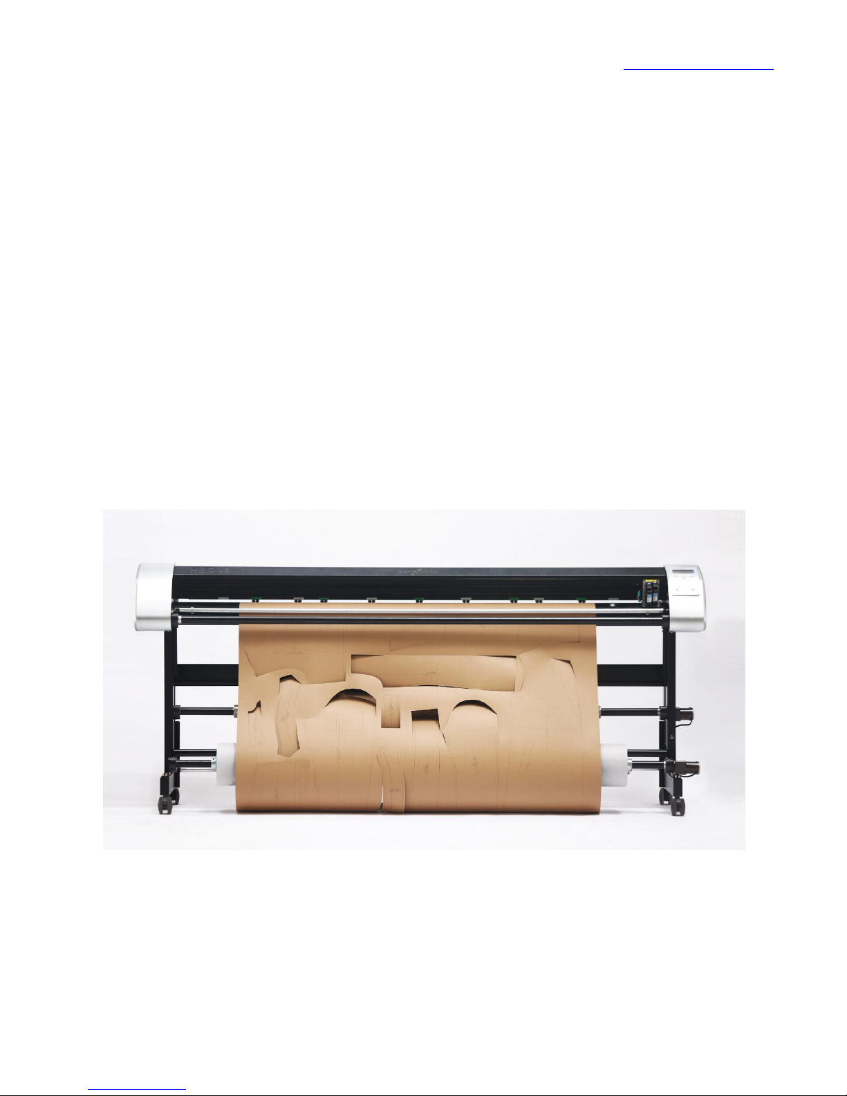
Thank you for choosing Han-bond H8 series vertical ink jet cutting machine.
H8 series vertical ink jet cutting all in one machine adopts double feeding paper
system (white paper and kraft paper can be loaded at the same time), and can be
used to drawing, cutting large format of clothing mark, luggage break the
pattern, engineering drawings, model etc., graph cut drawing quality reached the
international first-class results. H8 series vertical jet cutting machine’s servo
system is with high accuracy, fast speed, stable effect, can be compatible with
domestic and foreign clothing CAD software.
Page 11

www.han-bond.com
10
Basic performance index
Ink jet printing and cutting all in one machine series
Model No.
H8-120
H8-170
H8-190
H8-220
Max drawing area
1250mm*limitless
1750mm*limitless
1950mm*limitless
2250mm*limitless
Max feeding paper
width
1300mm
1800mm
2000mm
2300mm
Loading paper mode
Wheel feeding paper , automatic feeding paper (double feeding paper system)
Transmission mode
Han-Bond printing system+USB2.0
Original coordinate
setting
Can self set base point
Knife standard
diameter
2mm
Cutting material
Suitable for a variety of clothing special paper (60-350g)
Drawing material
Applicable to all kinds of clothing tail paper (40-200g), computer paper, kraft paper
(40-400g) etc.
Mas speed
Inkjet 100m2/h(highest), cutting 120cm/s (highest)
Nozzle No.
2PCS
Compatible cartridge
HP45
Resolution ratio
600dpi/300dpi
Compatible format
Any format (domestic and foreign clothing CAD software)
Mechanical
Resolution
0.025mm/step
Software resolution
0.05mm/step
Absolute accuracy
0.15% or 0.1mm
Repeatability
precision
0.2mm below
Concidence deviation
<0.5mm
Knife pressure
10g-300g
Drive mode
Servo. step
Power supply
AC input: 110V + 220V, 10%/60HZ + 10%/50HZ,220W
Page 12

www.han-bond.com
11
Computer system requirements
System Microsoft Windows XP
CPU Intel Core i5
Memory 2G
hard disk 500G
CD-ROM 4 times above CD-ROM
USB USB2.0 port
Page 13

www.han-bond.com
12
Chapter 1 assembly
1.1 Open box and check components
List of components: main machine x1, tripod beam x1, left foot rack x1, right
foot rack x1, universal casters x4, paper collection roller X1 article, send paper
drum X2, clutch paper cone x4, paper pressing rod X2, hp45 ink cartridge X2,
knife seat x1, vertical ink jet cutting machine lettering knife X3, assembly screws
X1 set, 5mm inner hexagon spanner x1, 3mm inner hexagon spanner x1,
adjustable fixing seat X2, power line x1, USB data lines x1, installation CD x1.
Page 14
www.han-bond.com
13
1.2 machine installation
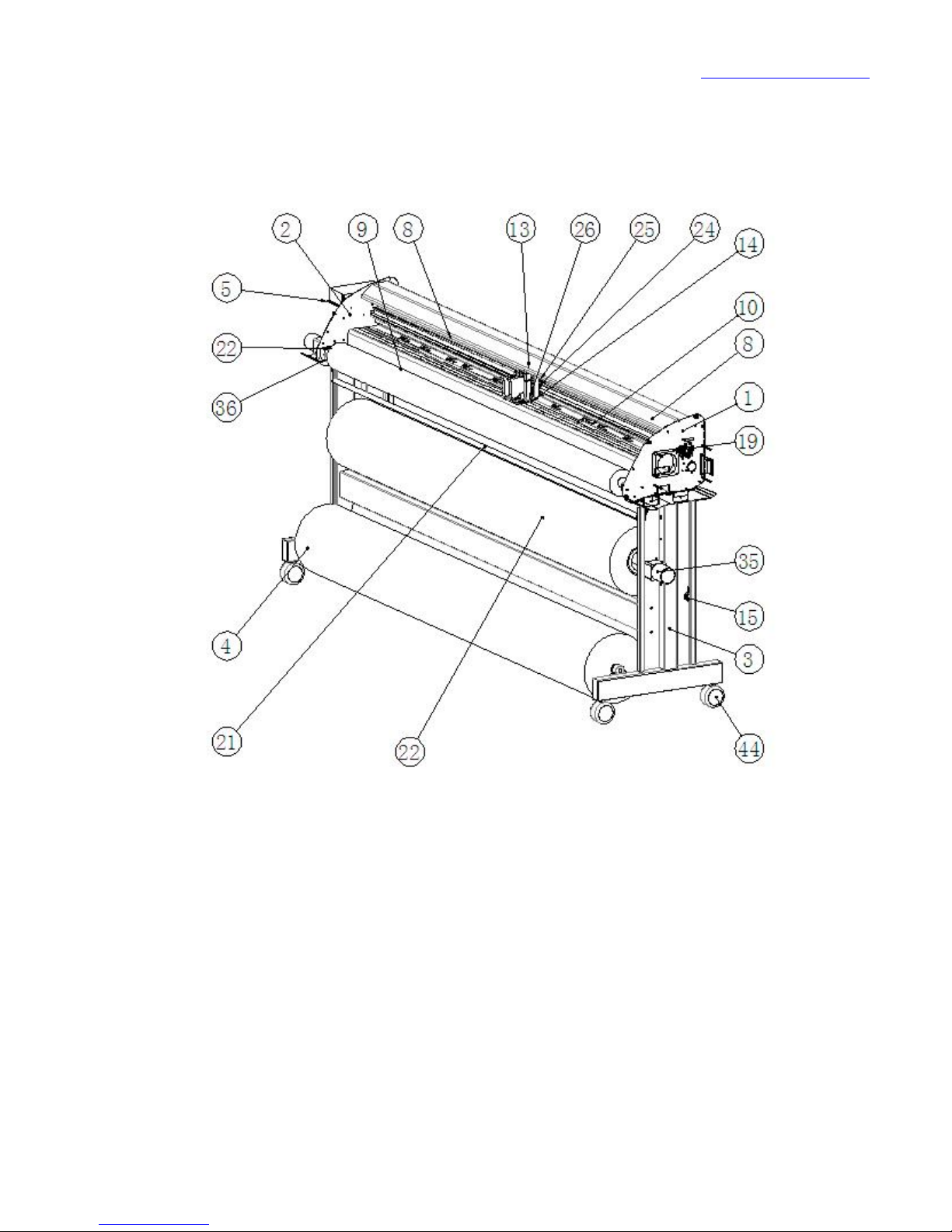
Figure 1 machine parts drawing
Name of all parts of the machine
1 the right side board 2 left and right foot plate
3 right tripod 4 left tripod
7 ink frame connecting plate 8 H8 slide
9 H8 tray 10 grinding wheel brace plate
13 ink cartridge mounting seat 14 press paper plate
Page 15

www.han-bond.com
14
15 Sensor holder 19 idler wheel group
21 collect and press paper bar group 22 paper collection roller group
35 paper feeding motor 36 roller base
44 universal caster
1.3 machine connection
1.3.2 connection USB data line
First to turn off the machine power, and the USB data line and machine
connection point need to use "can stick type fixed seat" stick firmly, prevent
because of external pull to damage the machine.
1.3.1 connection of power cord
When the power switch is in the state of '0' disconnect state, one end of the
power supply line is connected with the machine, and the other end is inserted in
the power supply board which is provided with a reliable ground wire protection.
If machine power supply is abnormal, please don't try to hold on to turn on
the power switch, should immediately unplug the power line, stop related
operations and contact with the dealer, feedback about the situation, identify
and eliminate all problems then can use.
Page 16
www.han-bond.com
15
1.4 install HP45 cartridge
1.4.1 cartridge type
H8 series of vertical jet cutting machine use HP51645 model cartridge, in
order to ensure the quality of printing, it is recommended to select the authentic
cartridge, HP supplies store sales.
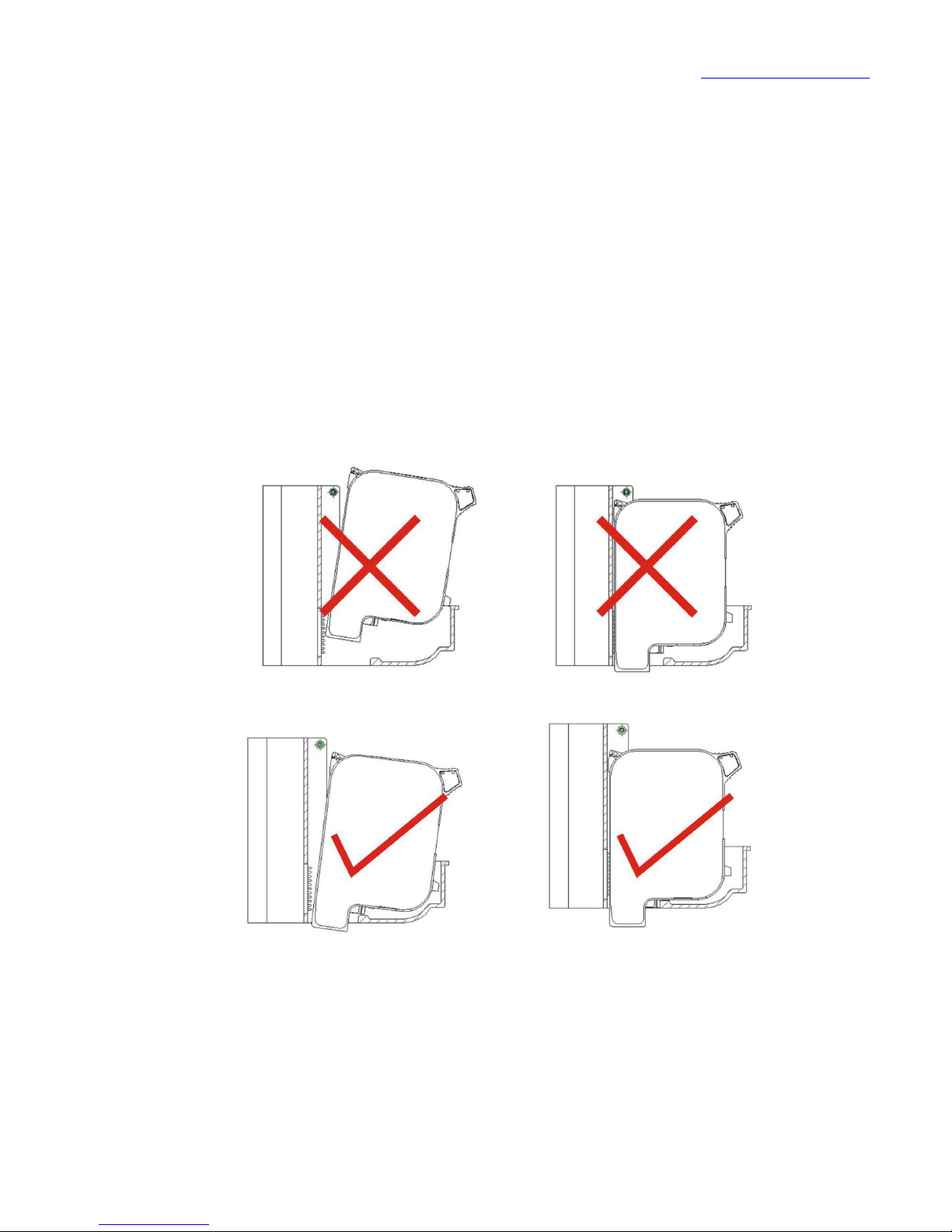
1.4.2 cartridge installation
Cartridge installation example (see Figure 3):
Figure 3 cartridge installation example
Page 17
www.han-bond.com
16
1.4.3 ink exhaustion mark
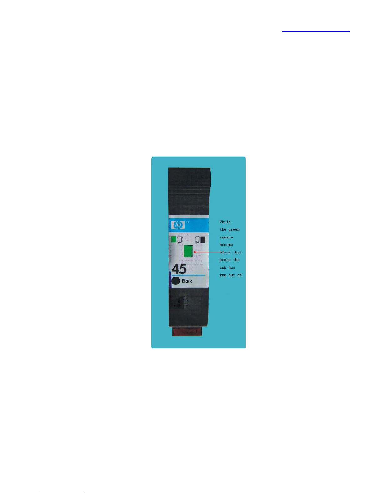
The ink of the cartridge during drawing process, the constant consumption;
ink exhaust mark will gradually change from green to black; if the mark is
changed to black completely, indicating that the cartridge has run out of ink,
need to replace the cartridge (see Figure 4).
Figure 4 ink exhaustion mark
1.4.4 exchange cartridge
When you need to replace the cartridge, please turn off the power of the
machine, plug in/off the cartridge should be cautious. Before printing a long file,
Page 18
www.han-bond.com
17
it is best to check the amount of ink cartridges, try to avoid in the middle of the
print to change cartridge.
1.4.5 cleaning cartridge
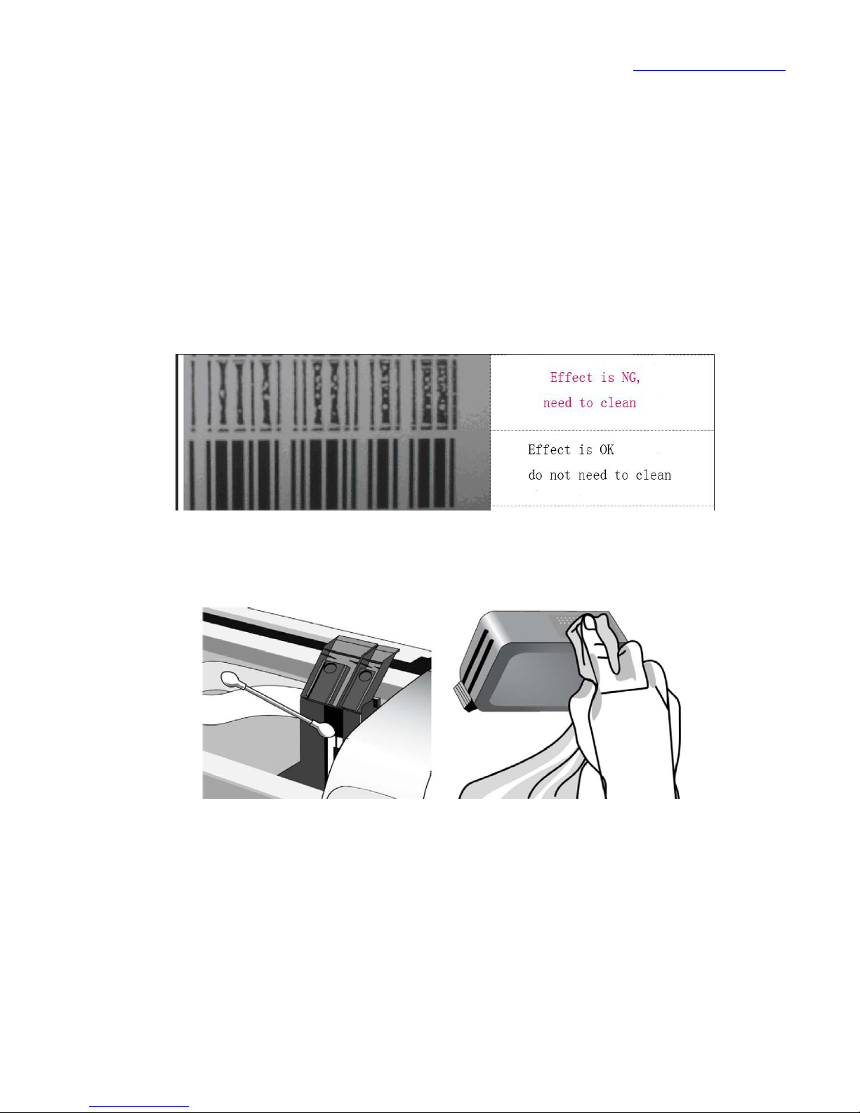
If the printing graphics have some points or lines not printed (see Figure 5),
you need cleaning cartridge.
Fig. 5 Comparison of printing effect
Figure 6 clean electronic contact 7 clean electronic cartridge PCB
Manual cleaning
A Clean the electronic contacts in the cartridge with a dry cotton swab (see
Figure 6).
Page 19
www.han-bond.com
18
B use dry cotton cloth to wipe the ink cartridge side PCB (see Figure 7) to
avoid damage to the PCB, should only be wiped once.
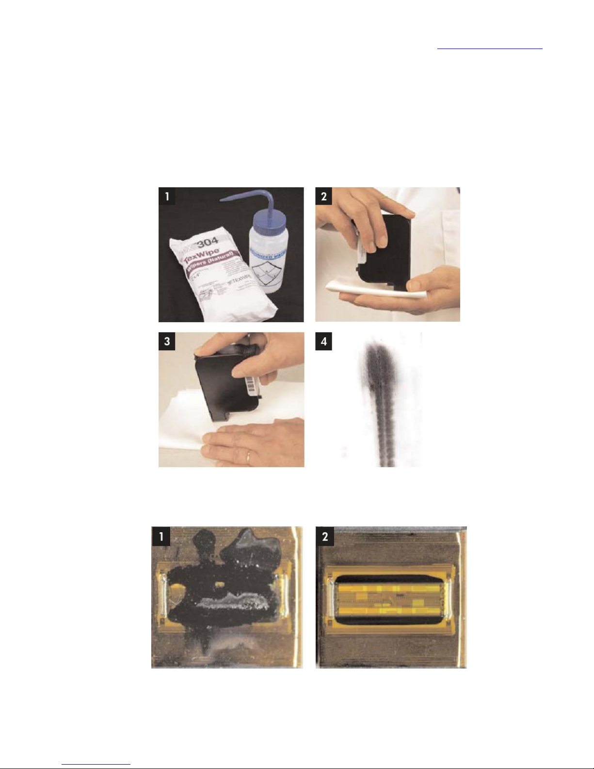
C To clean nozzle by non-dust cloth or cotton with alcohol(see picture
8,9,10).
Figure 8 cleaning cartridge nozzle
Figure 9 before cleaning figure 10 after cleaning
Page 20
www.han-bond.com
19
Auto clean
Press the "CLEAN" key in the standby mode, the nozzle can be cleaned
automatically.
1.5 mounting tool holder
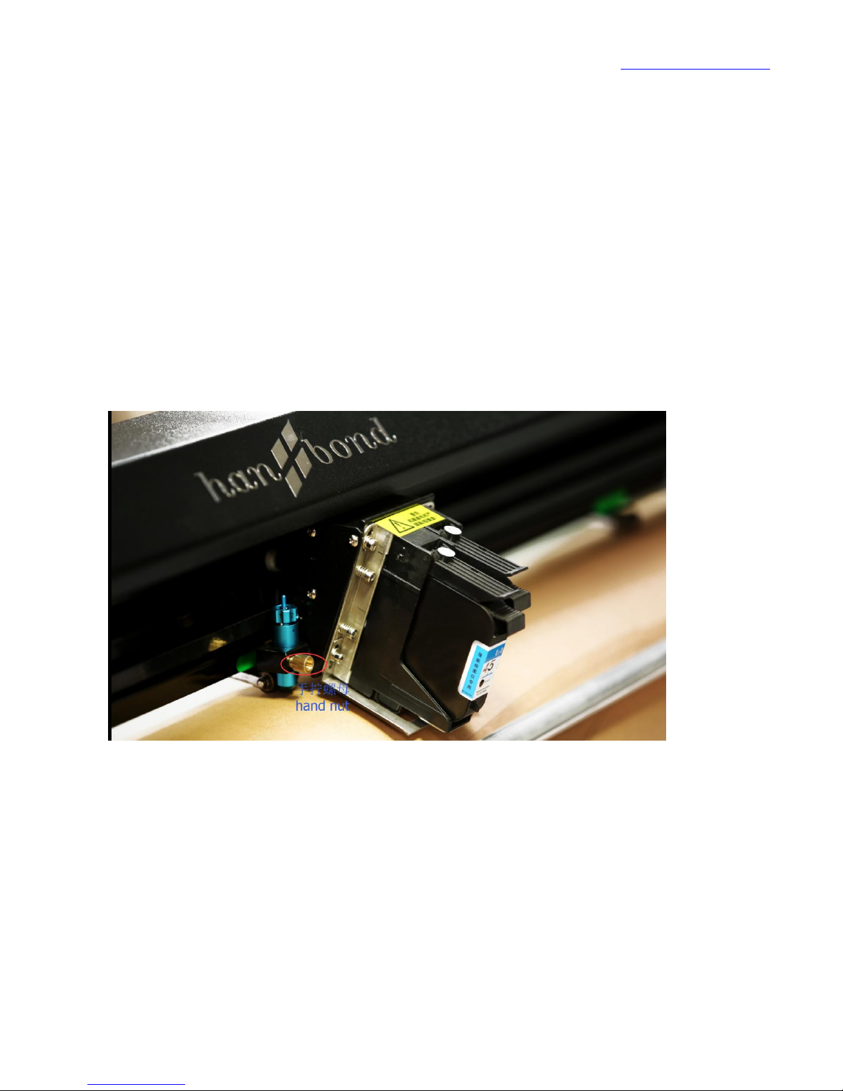
1.5.1 assemble and disassemble knife holder
Unscrew the hand nut , then you can pull up.
Page 21
www.han-bond.com
20
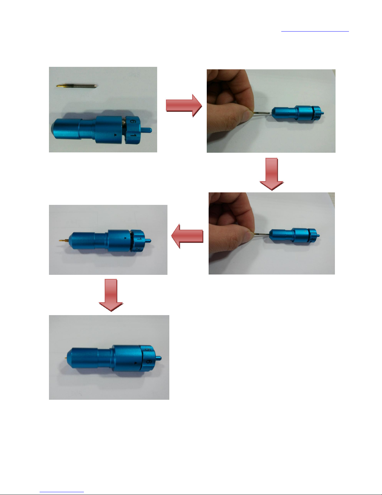
1.5.2 knife holder assemble diagram
Page 22

www.han-bond.com
21
1.5.3 The use of knife holder
Han-bond gear adjustment function Daotao (0~11 file), adjust the Han-bond
blade length is more simple, quick and accurate.
Daotao gear: knob marked with 1/2/3/4/5/6 numbers, the initial state
(clockwise twist in the end) for "0", 1 "digital gear 1" (when the blade length is
about 0.099 mm, and so on each gear blade length increases about 0.099 mm, 11
blade gear about 1 mm in length), the number 1 and number 2 for "gear 2", the
number 2 is "gear 3", and so on the number 6 as the "block 11". Special note:
clockwise and counterclockwise direction is gear, downshift, blade installation
must be reduced counterclockwise to file 0 file" .
Cutting different materials, can be directly adjusted according to the material
file, need to replace paper cutting blade or cutting blade at the time, for example:
250g kraft paper cutting knife, Han-bond can be adjusted to "3" (adjust the blade
length of about 0.297 mm). Note: due to the material density of different reasons,
blade length adjustable there will be differences, and also with the blade loss
degree and machine parameter settings.
1.5.4 Han-bond blade
Is a Japanese custom diamond blade blade hanbond, is 3~10 times the
normal life of the blade.
Page 23

www.han-bond.com
22
1.6 install printing / cutting papers
The print / cut paper instruction: weight: 40-300g, tube diameter 60~75 mm,
fiber container quality is less than 50kg.
H8 vertical ink jet cutting all in one machine, when the cutting mode is using
kraft paper (120g-300g) , the press wheel which is corresponding to the paper
feed grinding wheel need to be completely pressed well, when it is in the use of
clothing mark paper, computer paper, kraft paper (40-120g) drawing modes,
need to symmetric select five pressure wheel and press it them well (less than or
more than 5 wheel to press the paper that will affect printing).
This machine’s paper motor switch can control the paper roller to be
running or stopping, if you need to use the roll paper function, you need to open
the switch ( that’s switch it to "ON" position).
Page 24

www.han-bond.com
23
Chapter 2 installation drive
Note: When do printer driver installation, Windows XP, win7 32-bit computer
operating systems selected the folder "win7 32"; win7 64 bit computer operating
systems selected folder "win64bit". When installation, please must to select the
manual loading.
2.1load driver (for example : win7 64 bit computer operating system)
Copy and save the file, copy the "win7 64" folder which under the same
folder of this user manual folder to the computer at any location (in order to
facilitate the search, it is recommended to save it to the computer D disk).
Make sure the USB data line to be securely connected on the machine, and
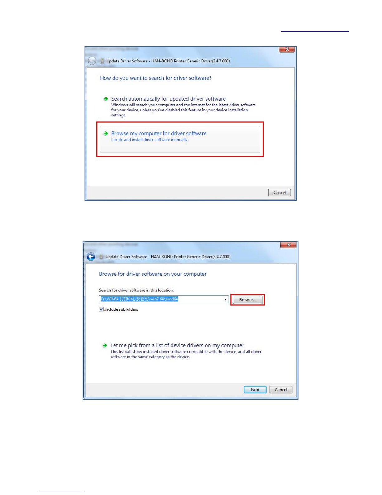
turn on the power switch of the machine, the computer will be prompted to
"update driver software (Han-Bond Printer)", began to enter the installation
process.
Page 25
www.han-bond.com
24
Select "browse the computer to find the driver software (R)"
Click “browse"
Page 26
www.han-bond.com
25
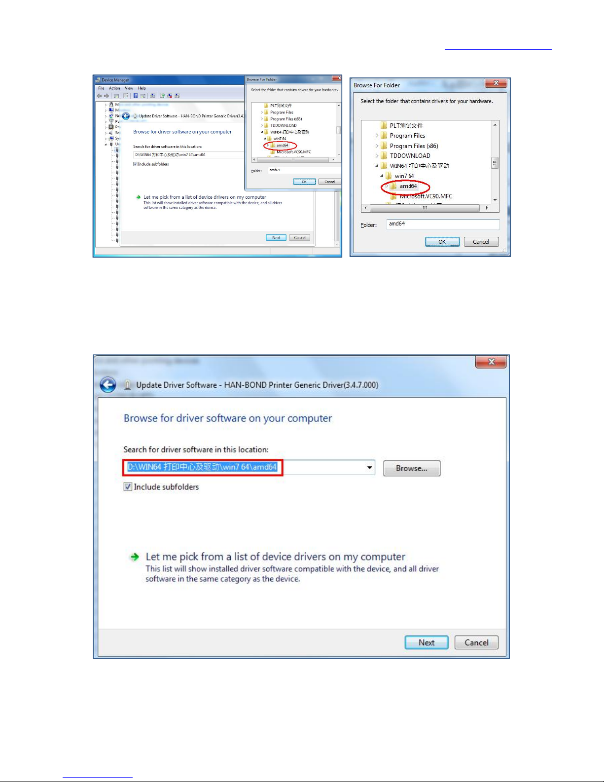
Select the "win7 64" folder in the first step copy path, open the "win7 64"
folder that under "win7 64" folder , click “OK” after selected.
Click "next"
Page 27
www.han-bond.com
26
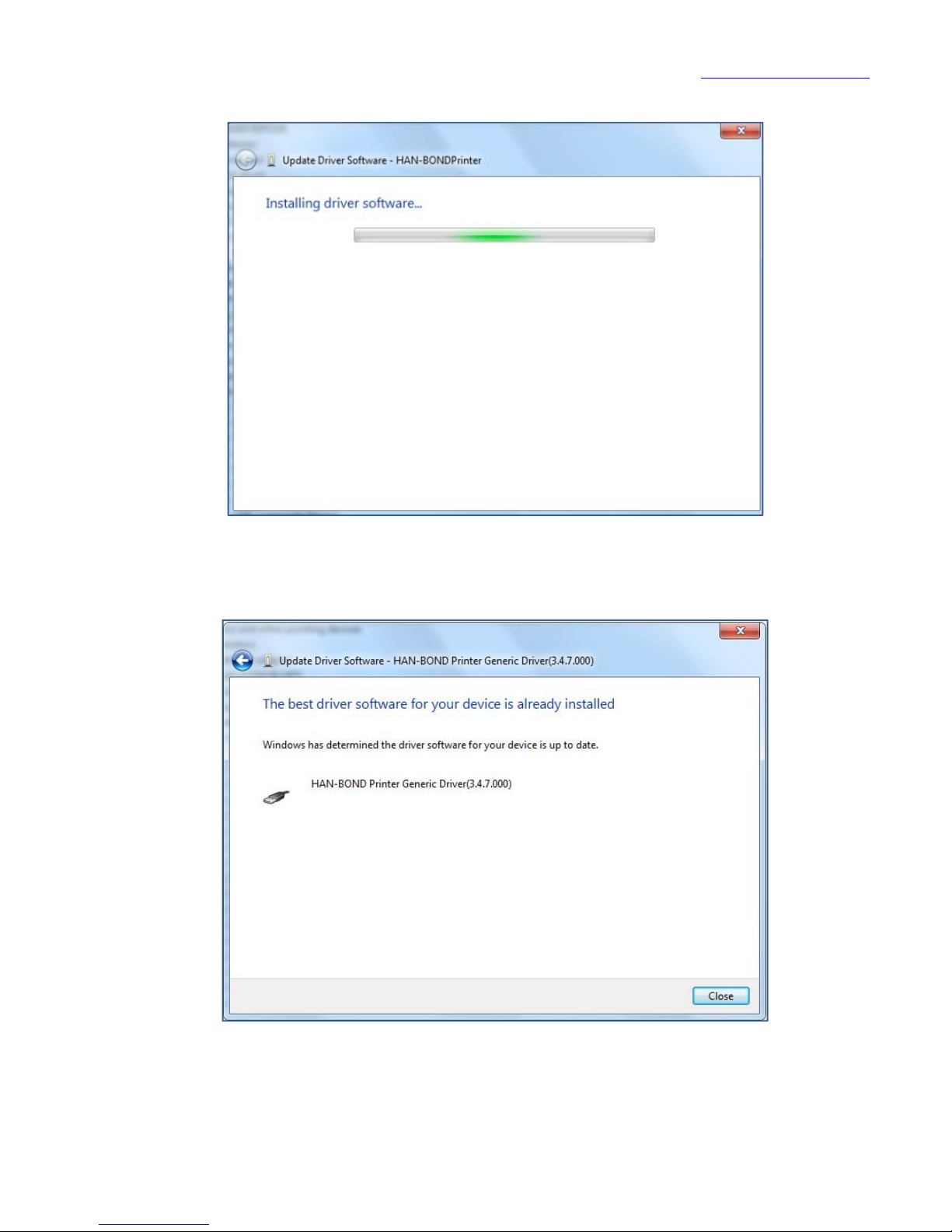
Load in...
Click "close"
Installation process complete!
Page 28
www.han-bond.com
27
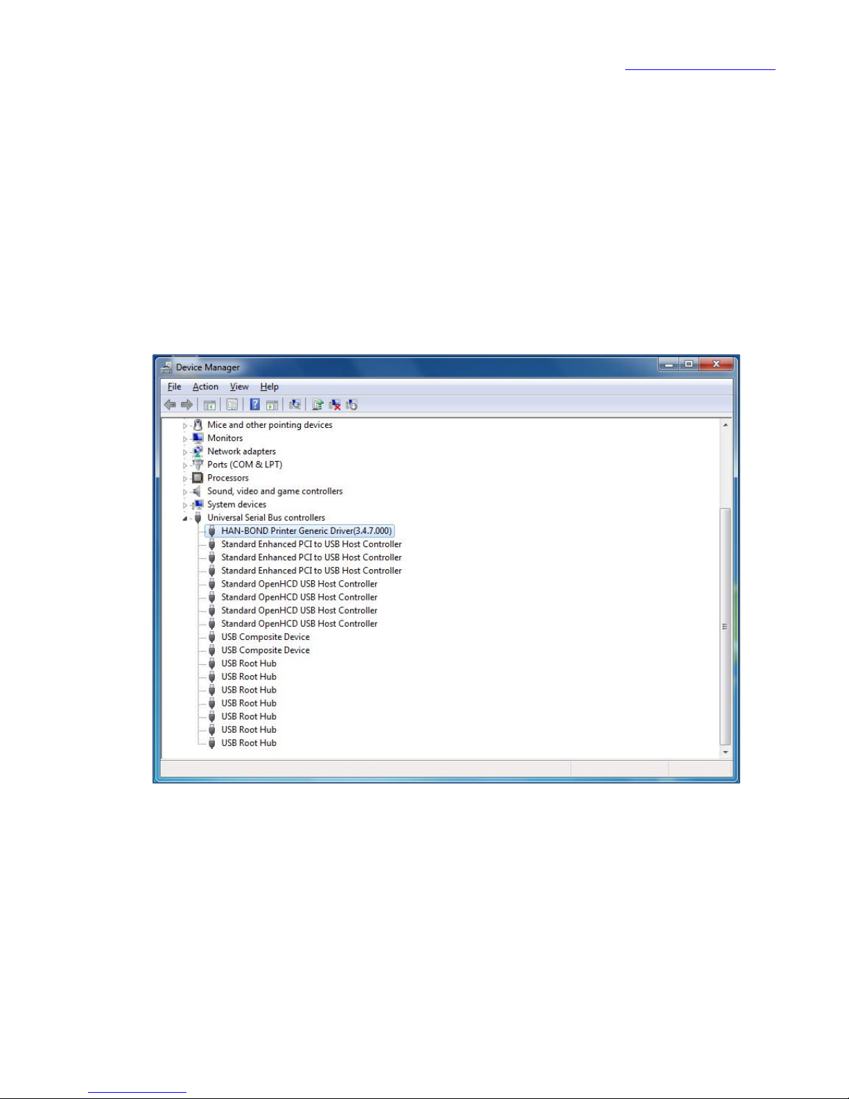
After the successful installation of the Han-Bond Printer driver, turn on the
power switch of the machine (the USB data line is in the connected state). Test
methods: 'my computer' position with the right mouse button to choose
"properties", open the "device manager", in the "universal serial bus controller"
can see the 'HAN-BOND Printer Generic Drive(3.4.7.000), which indicates that the
drive and connection is normal.
Page 29
www.han-bond.com
28
Chapter 3 installation and use of the output center
Note: when you select output center installation package, Windows XP, win7
32-bit computer operating system choice running the file "Han-Bond print
system 32bit"; win7 64 bit or above computer operating system choice running
the file "Han- Bond print system 64bit"!
3.1 output center installation (example: win7 64 bit or above computer
operating system)
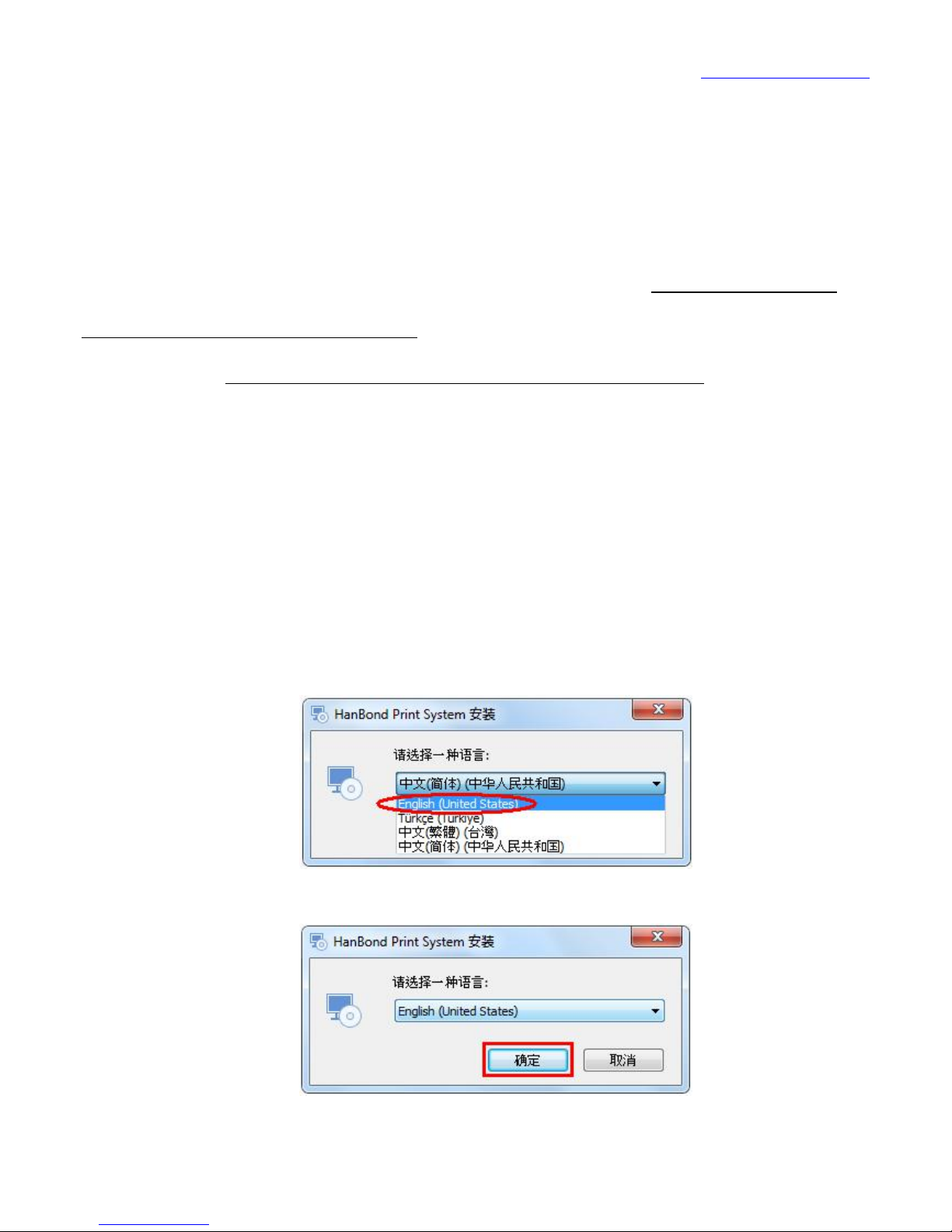
Run folder "Han- Bond print system 64bit- Print Center _USB interface
--Han-Bond Print System 64bit"
Page 30
www.han-bond.com
29
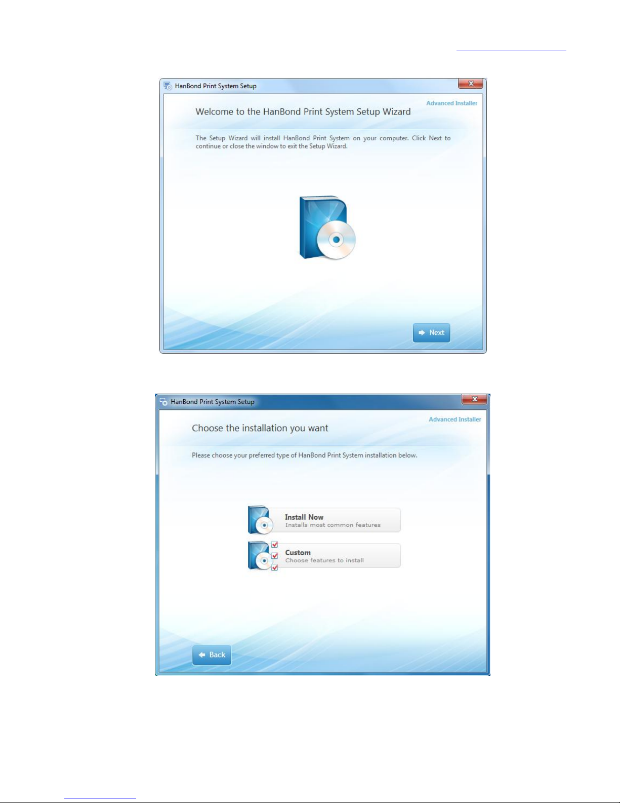
Click "next (NEXT)".
Page 31
www.han-bond.com
30
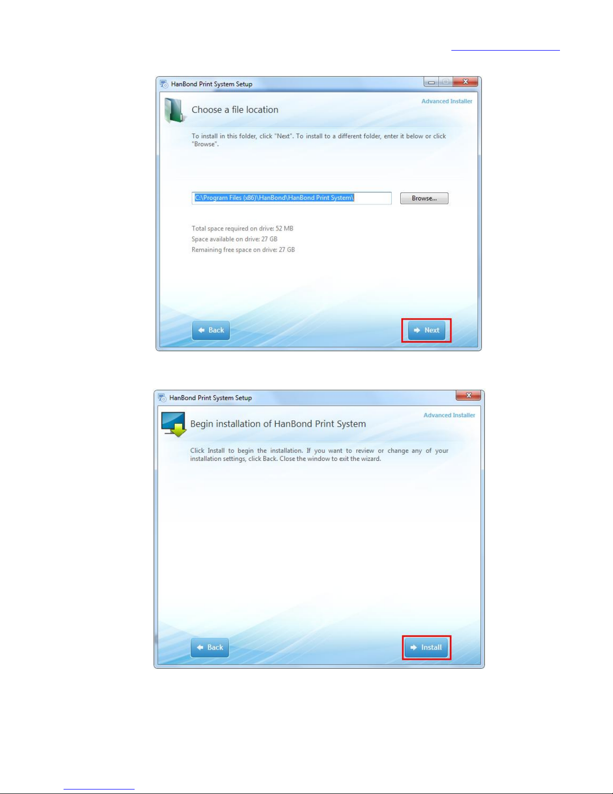
Click "next (NEXT)".
Click "Install".
Page 32
www.han-bond.com
31
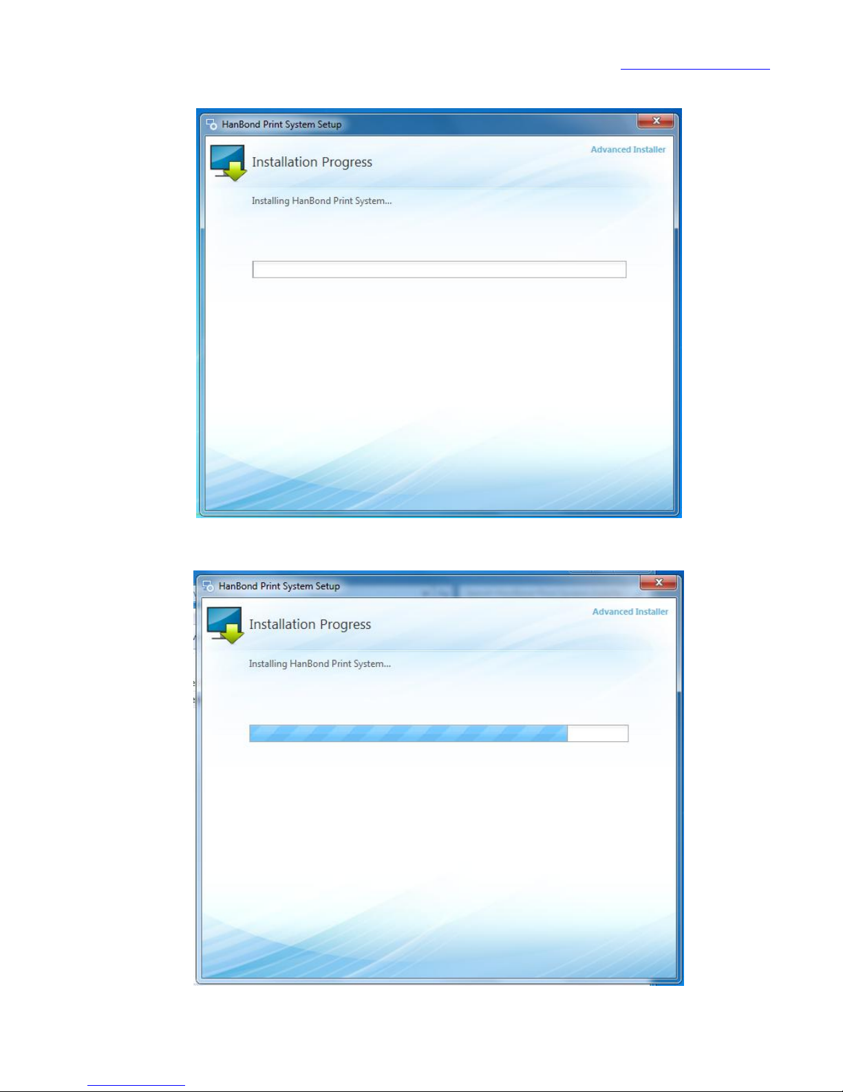
Installing...
Page 33
www.han-bond.com
32
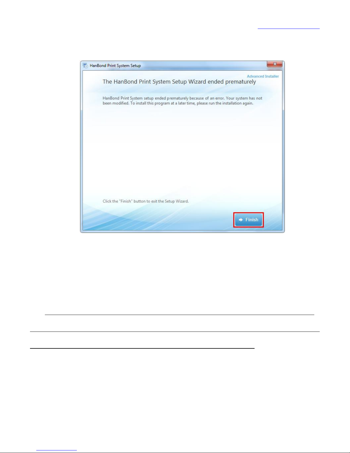
Click "finish".
Install is completed and run Print Center
Computer operating system for the installation of win7 64 can refer to
the steps of the computer operating system windows XP! But the loaded file
that need to select the file "Han-Bond Print System 64bit ".
Page 34
www.han-bond.com
33
3.2 the use of the output center
Han-Bond print system is a PC terminal software presented by Han-Bond
company, its functions include graphics browsing, printing, as well as graphics
editing and text notes, etc..
Before using, be sure to adjust the following settings options!
3.2.1 graphic direction setting
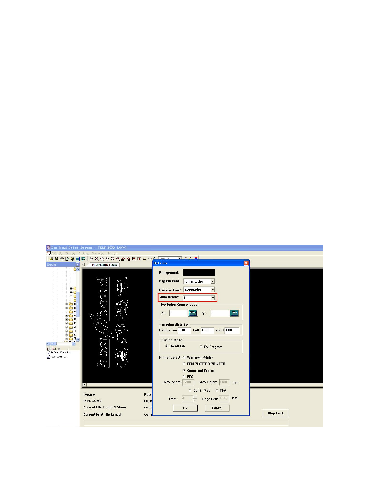
When the output is installed for the first time and need to set the image
direction and open a PLT files (random CD in attached file), In turn by the “ set -
Options - automatic rotation 0 degrees” to adjust the parameters, to ensure
that the graphics in the right direction.
Page 35
www.han-bond.com
34
3.2.2 page settings
Open the page settings, to confirm that the scaling ratio is 100%.
3.2.3 page header and footer settings
Header and footer: do not click the "use header print" and “use footer to
print". (usually print clothing marker is not required for headers and footers,
users can also fill the content in the blank, self definition of headers and
footers)
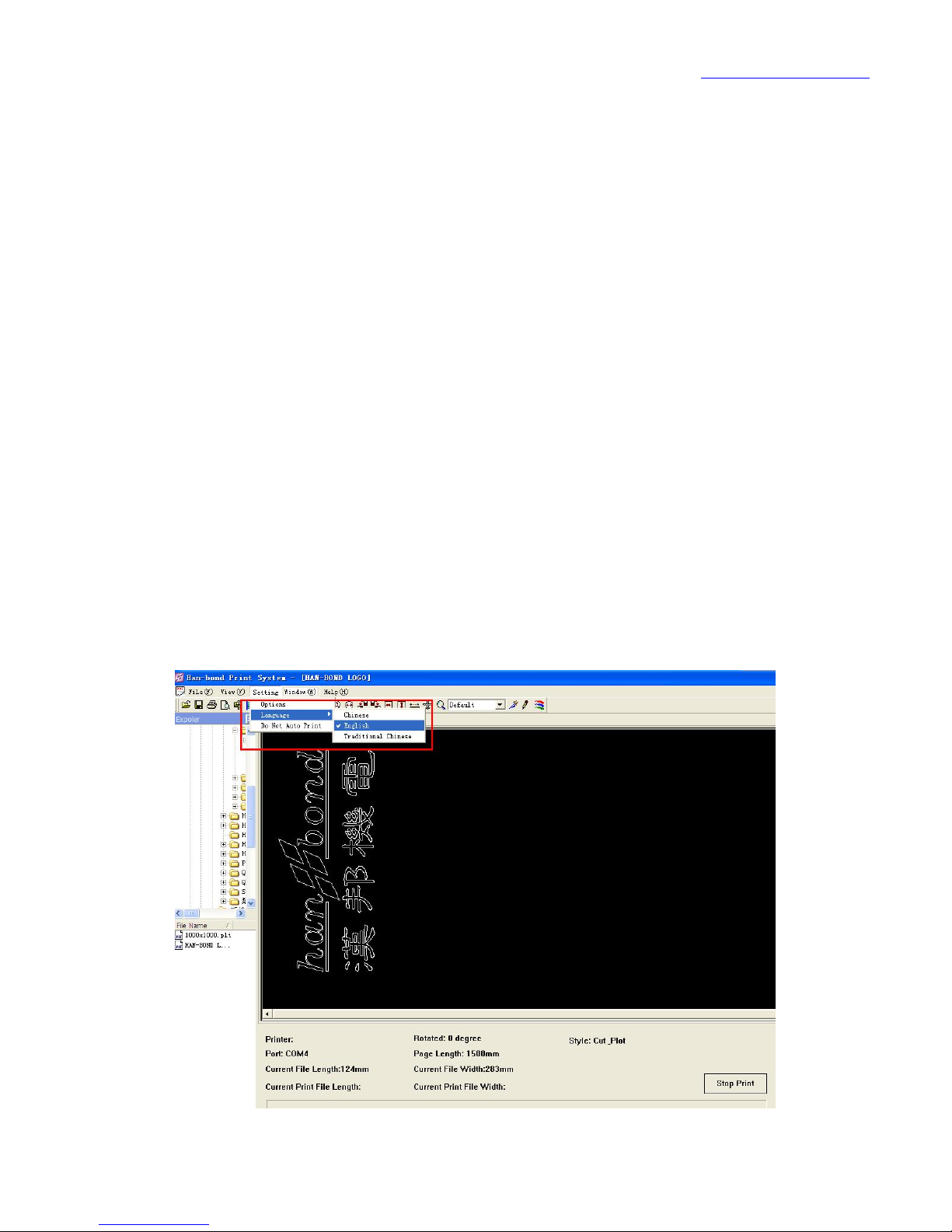
3.2.4 language selection
In the settings window second item can also be carried out setting in English
and Chinese.
Page 36
www.han-bond.com
35
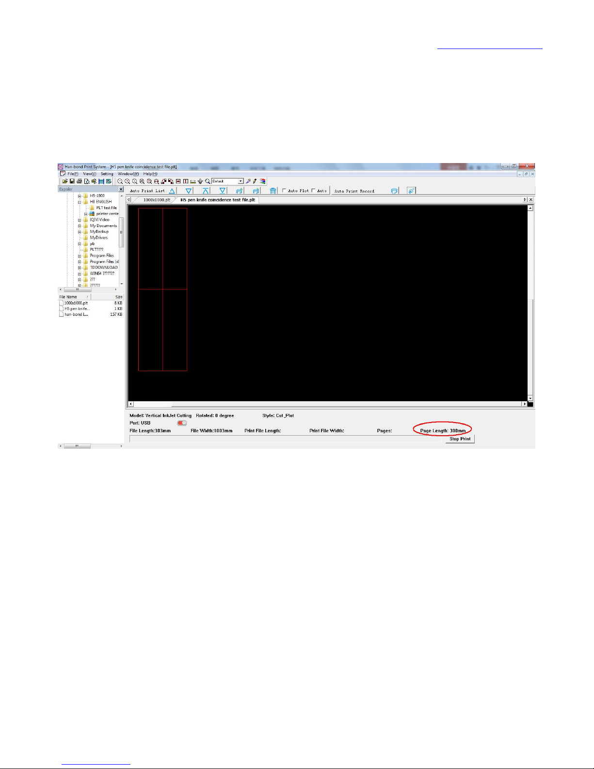
3.2.5 print segment length settings
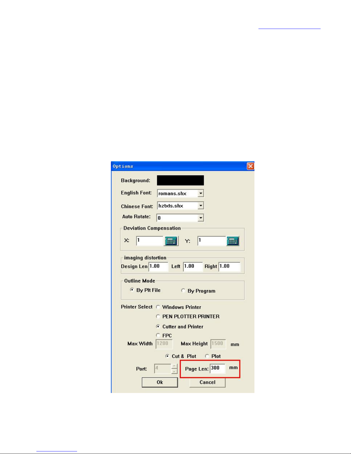
When chose cutting function, the segment length is set to 300mm, before
debugging pettifoggery coincidence it also needs to set the segment length to
300mm;
In the selection of the drawing function, the segment length does not need
to set, the default length of the software is 500mm.
Page 37
www.han-bond.com
36
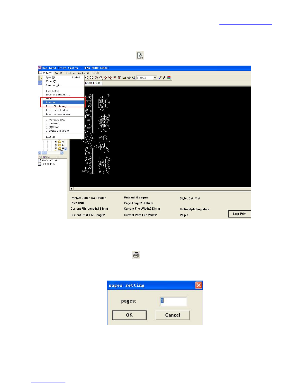
3.2.6 Print Preview
Open print preview, or click on preview the ready to print graphics.
3.2.7 print output
Open the print options or click , and enter the required number of print,
and then click OK".
Page 38
www.han-bond.com
37
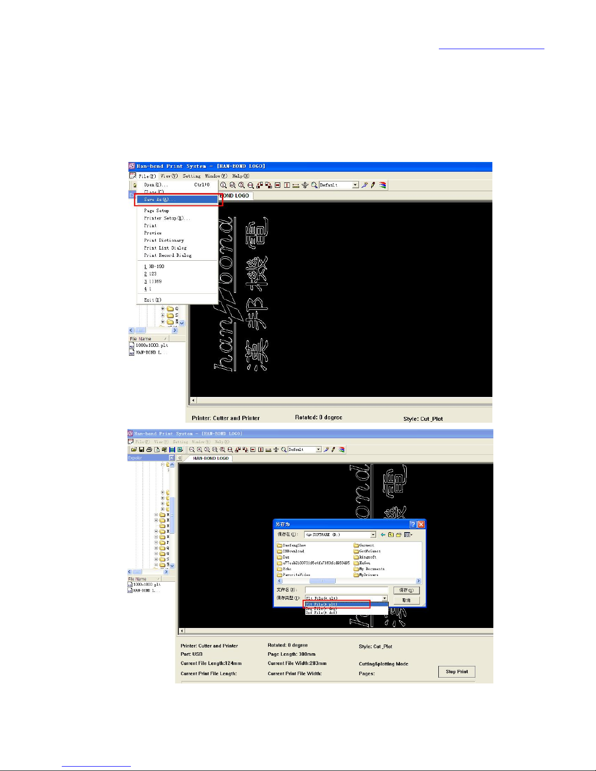
3.2.8 file conversion and save
Han-Bond print system support Plt. Dwg. Dxf and other types of print file to
save as conversion.
Page 39

www.han-bond.com
38
Chapter 4 control panel
4.1 control panel
The control panel is a human-computer interaction platform vertical spray
machine cut, the current state through a liquid crystal display device can
understand the machine; on the other hand, it is convenient for the operator to
realize feed wheel forward, back, left and right moving ink frame (drawing point
selection), the process of drawing the pause, stop, adjust the machine
parameters, dynamic self. A paper cutting operation and other functions.
4.2 key note
Figure 11 Key-press panel
Page 40

www.han-bond.com
39
【 】 —— draw back paper
【 】 —— paper feed
【 】 —— Left shift ink box group
【 】 —— right shift ink box group
【 】 —— Cancel the current print job
【 】 —— One key cutting paper function
【 】 —— One button entry test mode (b1~b5):
"b1. test X axis motor"
"b2. test Y axis motor"
"b3. test cutting"
"b4. test ink jet"
"b5 test cutting"
【 】 —— In the drawing process, if necessary,Press【 】,Vertical
jet cutting opportunity is in a suspended state,Press again【 】Continue
drawing。Standby state,Press【 】Is to redefine the origin of the machine,
Long press this button for 3 seconds to restore the data to the factory settings;
In settings,Press【 】Data save。
【 】 —— Enter settings,Press【 】,【 】Scroll parameter settings,
Press【 】,【 】Parameter addition and subtraction,Last press【 】Save
and exit。
Page 41

www.han-bond.com
40
Parameter setting check list:
Parameter setting
1.
Ink jet speed
[
MIDIUM
]
2.
Ink jet head split
[
0.00
]
3.
Nozzle coincident
[
0.00
]
4.
Row spacing split
[
0.00
]
5.
Ink jet speed shift
[
13000
]
6.
Row spacing join
[
0.0mm
]
7.
Nozzle selection
[
ALL]8.
Ink jet head selection
[
ALL]9.
Ink jet effect
[
CLEAR
]
10.
Cutting speed
[
80cm
]
11.
Full cut pressure
[
390g
]
12.
Half cut pressure
[
270g
]
13.
Half cut pressure
command
[
SP9
]
14.
Cutting length
[
50mm
]
15.
Cutting space
[
0.2mm
]
16.
X coincident set
[
0.0mm
]
17.
Y coincident set
[
0.0mm
]
18.
X axis scaling
[
1000.0
]
19.
Y axis scaling
[
1000.0
]
Page 42

www.han-bond.com
41
20.
Ink jet head maintenance
[
OPEN
]
21.
Tool nose radius
[
0.00mm
]
22.
Cut paper
[
CLOSED
]
23.
Collect paper motor
[
OPEN
]
24.
Paper type
[
Thick
]
25.
Language
[
English
]
26.
Factory Reset
[
Press OK 3”
]
Page 43
www.han-bond.com
42
Chapter 5 calibration
5.1 offset calibration
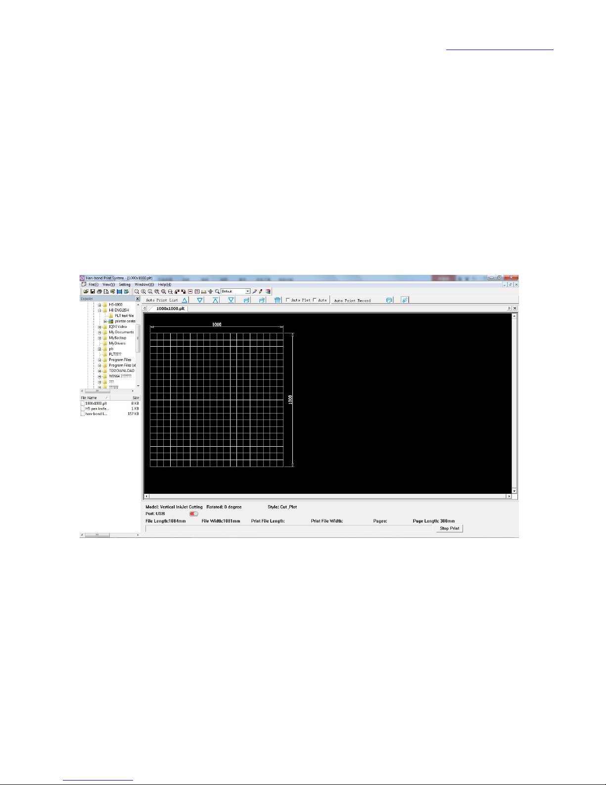
Shipped along with the machine there is a disk, select PLT test file
"1000X1000.PLT" in the disk, and print.
图 7 1000X1000.PLT
5.1.1 calibration nozzle dislocation
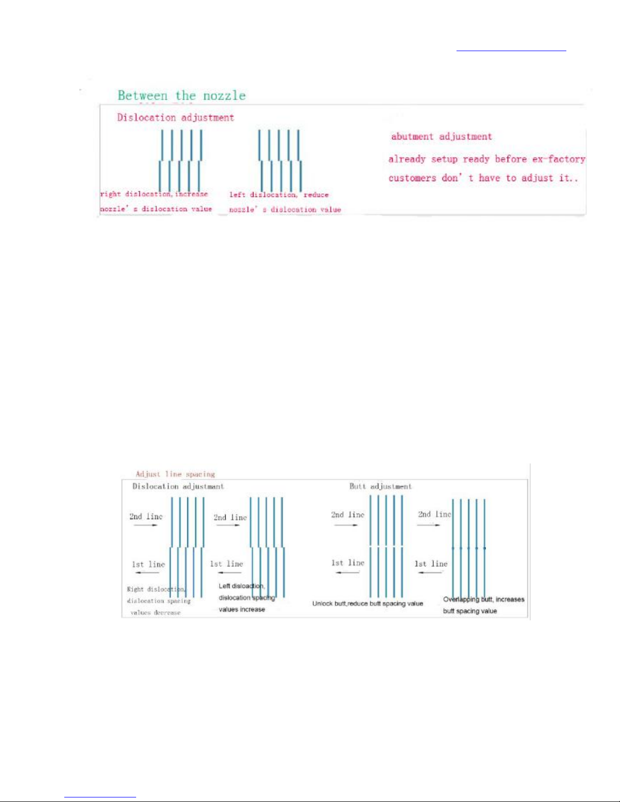
When the nozzle is dislocation to the right side (Fig. 8), increase parameter
value in the 2nd item [nozzle dislocation] parameter, otherwise, decrease the
value;
Page 44
www.han-bond.com
43
Figure 8 sprinkler head dislocation
5.1.2 calibration of row spacing dislocation
If row spacing dislocation is to the right side (for example, figure 9 left),
increase the parameter value in the parameter set of 4th item [ spaced
dislocation ], contrary to reduce numerical;
When the row spacing front and back is disconnecting dislocation (for
example, figure 9 right) , reduce parameter value of the parameter setting item 6
[row spacing docking], and conversely increased the parameter value;
Figure 9 spacing dislocation
Page 45
www.han-bond.com
44
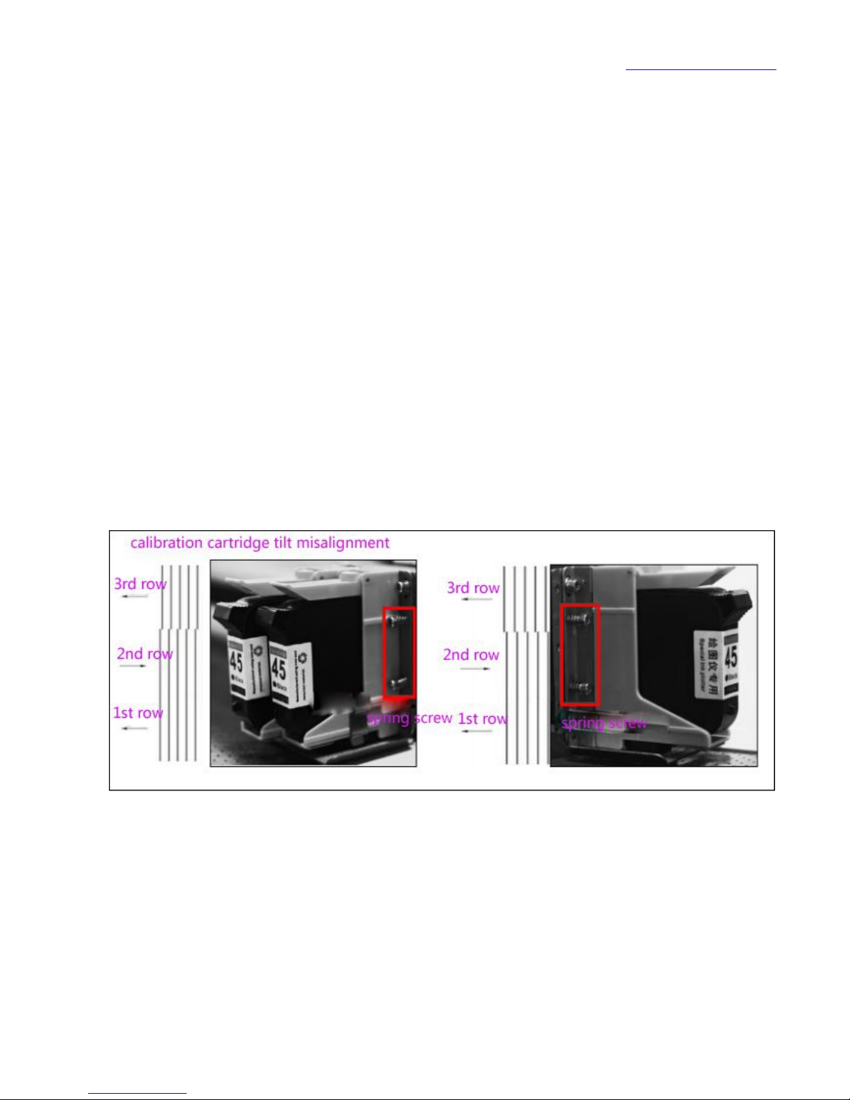
5.1.3 calibration cartridge tilt misalignment
Ink box frame’s tilt lean to the left dislocation (FIG. 10 cases, right), tighten
the spring adjusting screw on the left of the ink holder.
(Before adjustment, the 2 fixed screws on the left of the ink box rack must be
all unscrewed)
Ink box frame’s tilt lean to the right dislocation (FIG. 10 cases, left), tighten
the spring adjusting screw on the right of the ink holder.
(Before adjustment, the 2 fixed screws on the right of the ink box rack must
be all unscrewed)
Figure 10 ink box tilt adjustment
5.2 precision calibration
Due to the existence of the CAD software of the clothing coefficient error,
before using vertical ink jet cutting all in one machine must to be carried out
Page 46
www.han-bond.com
45
precision calibration, the user can through "Han-bond printing system" or
"clothing CAD software” to realizing graphic precision correction. To correct
"clothing CAD software", please consult the software company, following are the
correction method of “Han-Bond printing system"!
Note: the same software corresponding to the machine is with same
compensation coefficient, it needs to re -adjust after changing the software !
Calibration print 1000X1000mm rectangular file to do calibration, the file
need to use the corresponding clothing CAD software to generate.
Print 1000x1000.plt calibration file
Measuring the actual print length, for example: the feed paper direction is 999mm
Page 47
www.han-bond.com
46
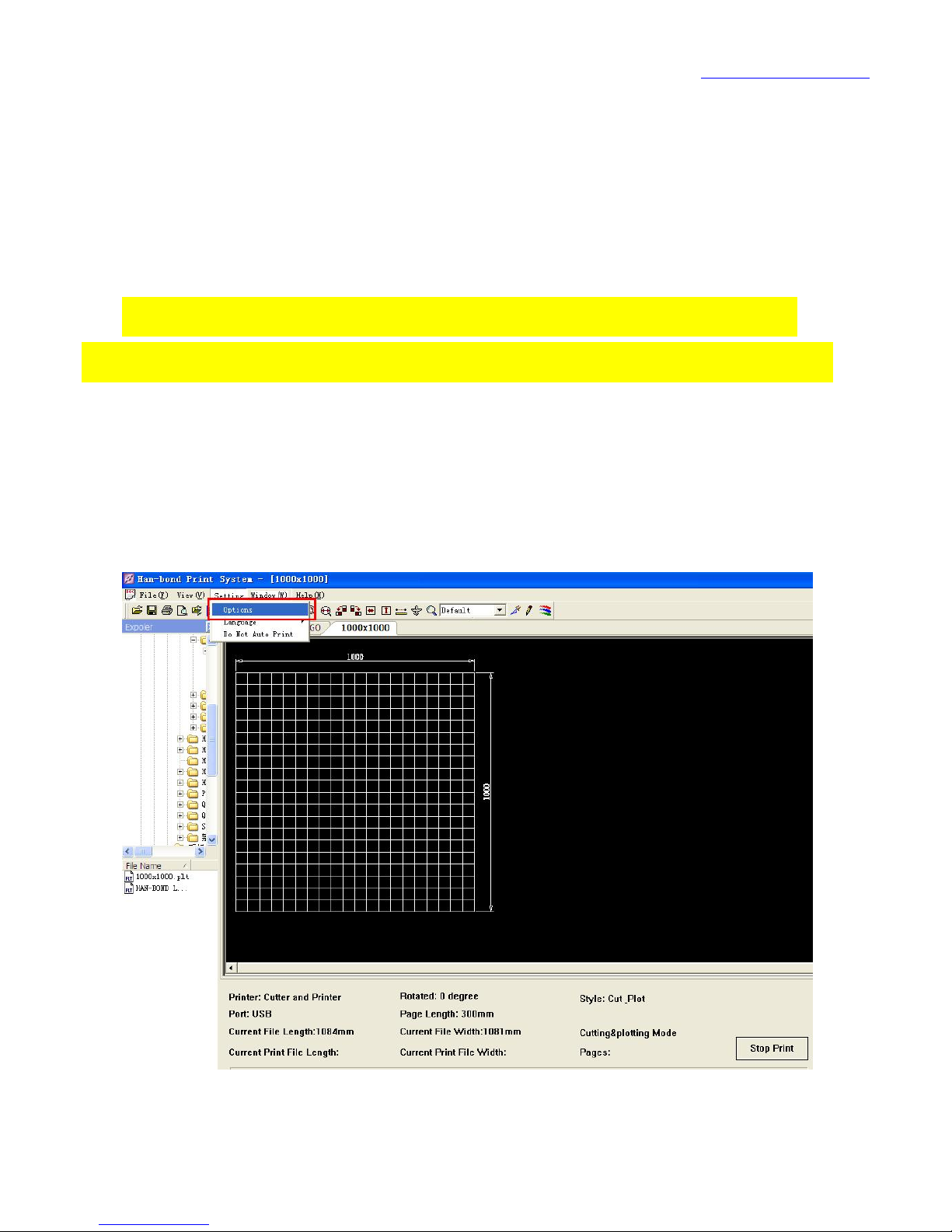
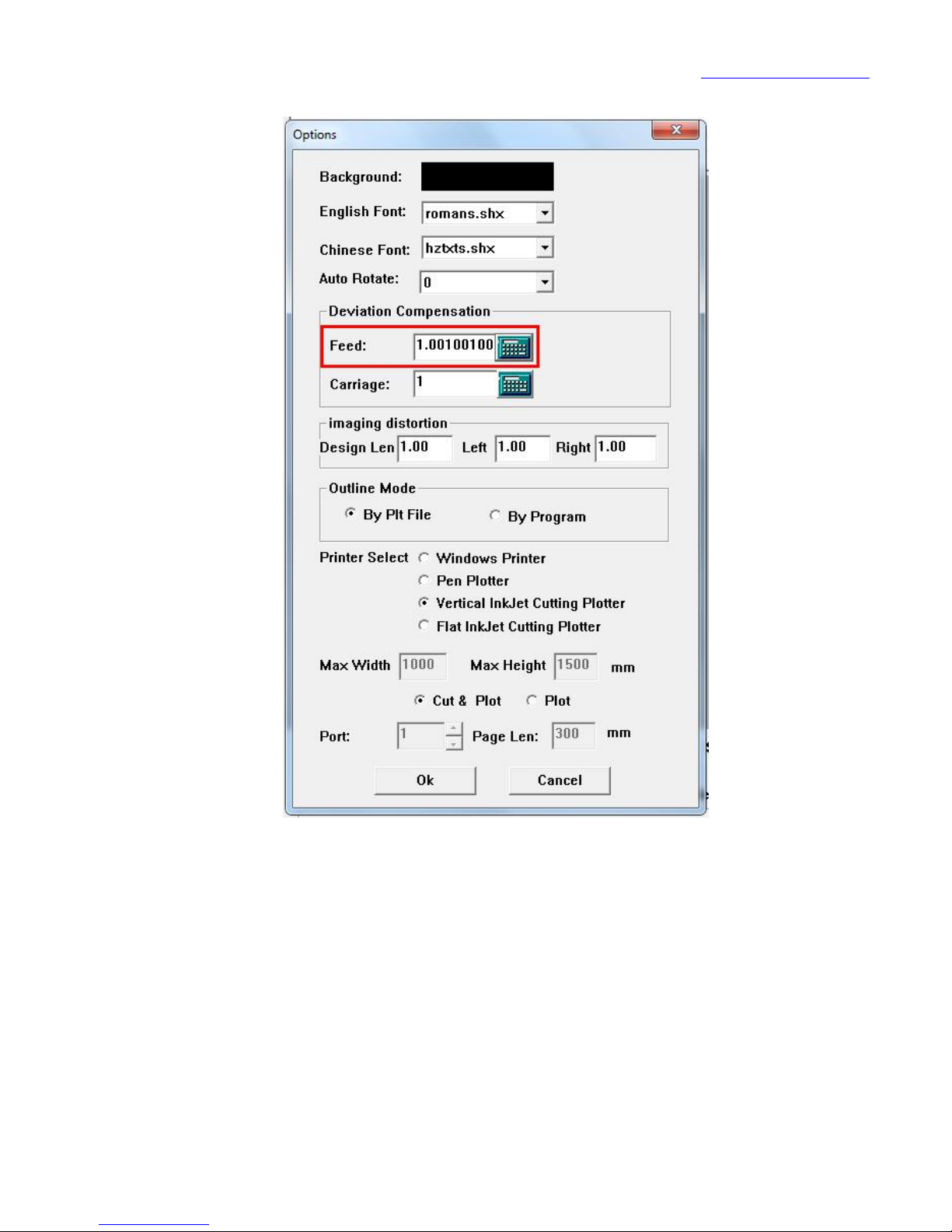
In Han-Bond printing system click "Settings"--> “ option. "
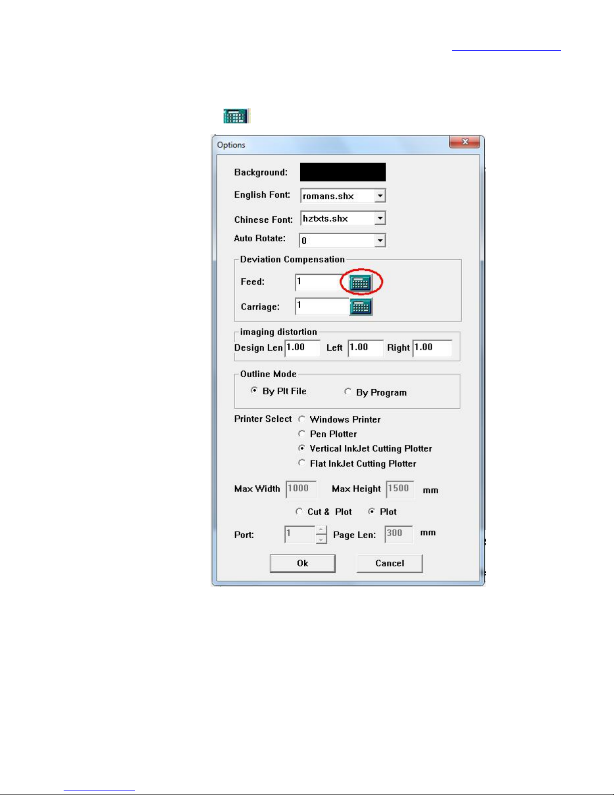
Click on the right side of the “paper feeding direction “.
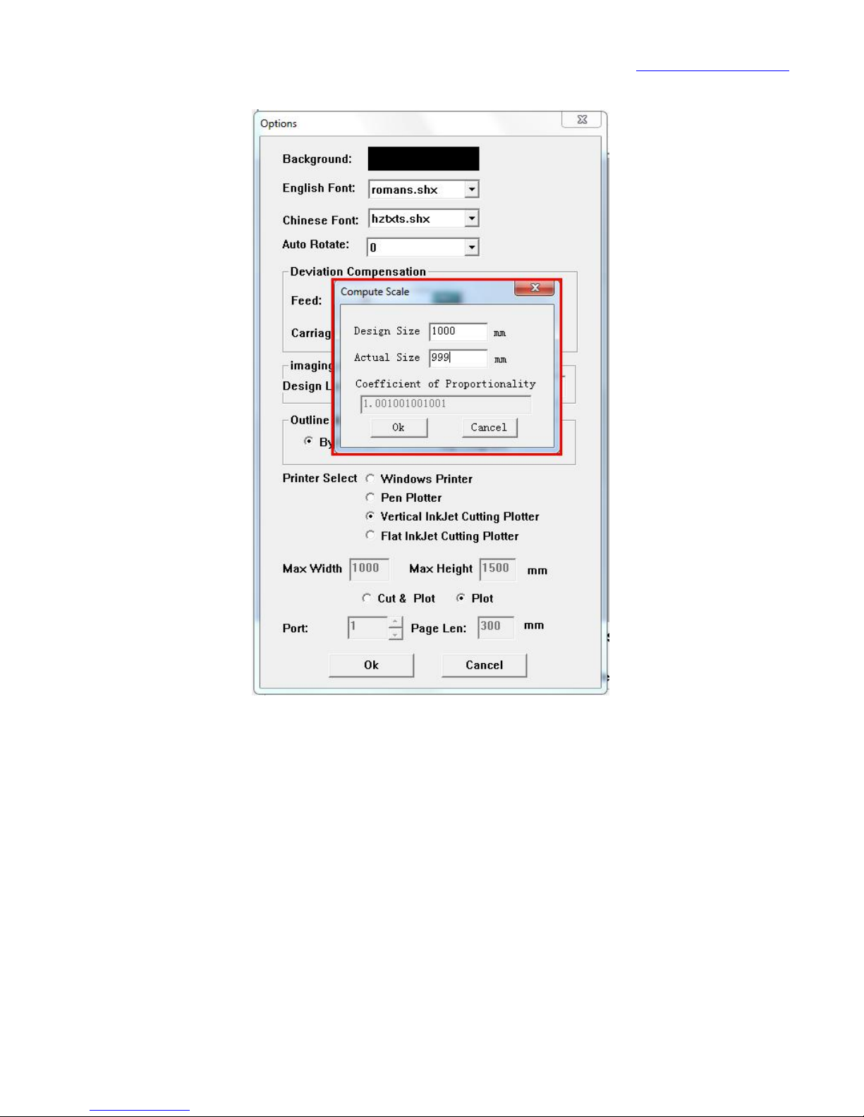
Enter the design size and the actual size, and click "confirm"
Page 48
www.han-bond.com
47
Han-bond printing system automatically help you calculate the
compensation coefficient of “feed direction"
Page 49
www.han-bond.com
48
The setting method of compensation coefficient in the” direction of the
car “ is the same as above!!!
5.3 pettifoggery coincidence set
Shipped along with the machine there is disk, select test file "H8 pettifoggery coincidence
set " in the disk and print,
Page 50
www.han-bond.com
49
Start debugging pettifoggery coincidence.
Note: before the operation, the segment length of the output center must be set
to 300 mm
Now to analyse the printed and cut file:
Page 51
www.han-bond.com
50
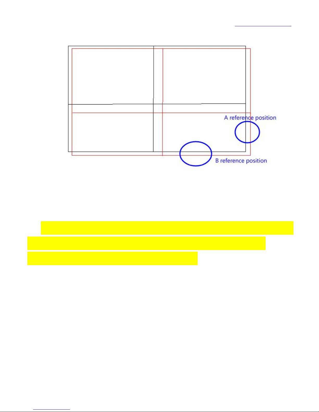
Figure 11 X/Y coincidence effect diagram
("---black line" is ink jet lines, --- "red line" is cutting line)
Note: all of the following parameters must be adjusted during machine in the
standby mode or during ink jet period. If it’s in the parameters of the
adjustment during the cutting process are not valid.
The first step: take (Figure 11) "a reference position" as an example, when the
cutting line in the right-hand of ink jet line, need to increase the control panel
item 16th [x axis coincides set] corresponding value, contrary to reduce
numerical;
The second step: take (Figure 11) "B reference position as an example, when
the cutting line in the jet line below, it needs to increase the control panel
Page 52
www.han-bond.com
51
seventeenth [Y axis coincidence set] the corresponding value, contrary to reduce
numerical;
Complete the debugging of X, Y axis of the coincidence set
Again to print the file "H8 pettifoggery coincidence settings file, start
debugging pettifoggery scaling.
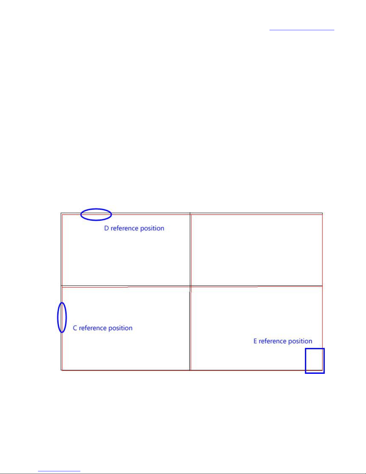
Note: reference E reference position, after adjusting the X/Y axis coincidence
set, then you can to carry out this operation.
Figure 12 X/Y coincidence effect figure 2
("---black line" is ink jet lines, --- "red line" is cutting line)
Page 53

www.han-bond.com
52
The third step: take (Figure 12) "C reference position" as an example, when
the cutting line in the right-hand of ink jet line, reducing the control panel item
18th [X-axis scaling] corresponding value, otherwise to increase the value.
The fourth step: take (Figure 12) "D reference position" as an example,
when the cutting line in the jet line below, the need to reduce the control panel
19th [Y axis scaling] the corresponding numerical value, and on the contrary to
increase the value;
Page 54

www.han-bond.com
53
Chapter 6 failure analysis
6.1 control panel error and solution
6.1.1 X encoder error
Solution:
1.Check the sensor head in the dolly board and grating ruler’s assembly
position, if grating ruler is not in the middle region of sensor groove, need to
adjust it well.
2.check the grating ruler paste is loose, loose grating ruler can not
guarantee the accuracy of the sensor area, please be carefully tear off and
re-paste it by using the double side adhesive;
3.check whether the surface of the grating ruler is contaminated with dirt,
wipe clean with cotton cloth;
4. to check whether the appearance of the grating ruler is worn, the worn
grating ruler can not guarantee the accuracy of the grating, please replace it
immediately;
5.grating ruler under the strong light, may affect the accuracy, please avoid
the glare of the area;
6.check X axis direction of the belt is off or broken;
Page 55

www.han-bond.com
54
6.1.2 display "AAAAAA"
Solution:
1. need password to unlock, please contact the dealer.
6.2 other issues analysis
7.each time to print file, the front section of the print blank or print is not
clear, may be the indoor temperature is too low, indoor temperature is less than
10 degrees, it is recommended that the machine be moved to work in the studio
with heating supply.
8.The machine in the printing process, if the car suddenly left and right
jitter, it may encounter strong interference source, please immediately shut down
and eliminate interference.
9.Print line is dotted line, please shut down machine and pull out cartridges,
then use cotton wipe ink nozzle; cleaning method refer to (Figure 18).
10.If the printed line moves along the direction of the nozzle there is a gap
of about 2mm wide blank, and nozzle each movement appear the same problem,
may head is not in place or loose cable plug nozzle.
11.Car around a large difference between the left & right scanning speed,
may be the fault of the transverse servo motor.
Page 56

www.han-bond.com
55
Chapter 7 contact way
Shenzhen Han-Bond Technology Co.,Ltd
Company address: China Shenzhen Baoan District Fuyong Street rainbow colorful
city Xiamen stone garden building B room 1306
Tel: 86-755-61508810
Fax:86-755-61508813
Quanjiao Han-Bond Technology Co.,ltd
Company address: Han-Bond Industrial Park,Yang Qiao Economic Development
Zone, Quan Jiao County, Chu Zhou City, Anhui Province, China , Zip Code
239500.
Tel: 86-550-5185755/655
Fax: 86-550-5185500
Company website: www.han-bond.com
Customer service Tel: 400-068-1698
Thank you for your selection of Han-Bond technology H8 ink jet cutting all in one
machine.
 Loading...