

Hanbell RC2-100AF, RC2-140AF, RC2-200AF, RC2-230AF, RC2-260AF Series Manual
...
0
CONTENTS
1. Compressor’s characteristics ............................................................................................................................. 2
2. Compressor specification .................................................................................................................................... 3
2.1 Design specification .................................................................................................................................... 3
2.2 Compressor outline ..................................................................................................................................... 5
2.3 Compressor construction ......................................................................................................................... 28
2.4 Capacity control system ........................................................................................................................... 30
2.5 Compressor application limits ................................................................................................................. 33
2.6 Compressor design feature ...................................................................................................................... 35
2.7 MCC and LRA ............................................................................................................................................. 37
3. Compressor handling and Installation ............................................................................................................. 41
3.1 Compressor handling ............................................................................................................................... 41
3.2 Mounting the compressor ........................................................................................................................ 41
4. Lubricant .............................................................................................................................................................. 64
4.1 Pre-cautions in changing of oil ................................................................................................................ 64
4.2 Changing of oil .......................................................................................................................................... 65
4.3 Lubricants table ......................................................................................................................................... 66
5. Electrical data and design ................................................................................................................................. 67
5.1 Motor design .............................................................................................................................................. 67
5.2 Compressor protection devices .............................................................................................................. 69
5.3 Power supply ............................................................................................................................................. 69
5.4 Selection of magnetic contactor .............................................................................................................. 71
5.5 Grounding .................................................................................................................................................. 71
6. Compressors accessories ................................................................................................................................. 72
6.1 Compressors standard and optional accessories ................................................................................. 72
6.2 Description of accessories ....................................................................................................................... 73
7. Operation and trouble shooting ........................................................................................................................ 87
7.1 Compressor start-up ................................................................................................................................. 87
7.2 System adjustment .................................................................................................................................... 89
7.3 Compressor stop ....................................................................................................................................... 91
7.4 Troubleshooting ........................................................................................................................................ 92
7.5 Compressor checking list......................................................................................................................... 95
8. System applications ........................................................................................................................................... 96
8.1 General application ................................................................................................................................... 96
8.2 Economizer application .......................................................................................................................... 109
8.3 Important notice to compressor application ........................................................................................ 112
8.4 Example of installation ........................................................................................................................... 113
Appendix 1. Compressor noise level .................................................................................................................. 116

1
Introduction
The Hanbell RC2-F series semi-hermetic twin-screw compressor inherits all the quality and experience of our
RC2 series compressor. The RC2-F series compressor is developed especially for application with Freon in
flooded system or refrigeration field. With a built-in high operating load design and advanced 5 to 6 Patented
Screw Rotor Profile, each compressor has high efficiency and reliability in all operating condition. Each unit is
carefully manufactured and inspected by high precision THREAD SCREW ROTOR GRINDING MACHINE, CNC
MACHINING CENTER, and 3-D COORDINATE MEASURING MACHINE. Each compressor at HANBELL also
follows the ISO 9001 certification quality system which assures the best quality control and production process to
customers. RC2-F series compressor has 27 models RC2-100~RC2-1530, with displacement (50/60Hz) from 98
/ 1 18 m3/hr to 1539 / 1847 m3/hr.
The RC2-F series compressors use high quality bearings which resulted in longer bearing life compare to
competitors. These bearings provide strong support to screw rotors especially for the heavy duty application.
Oil/Refrigerant injection port can be utilized when external cooling is needed at chamber. This can keep the
compression chamber at proper discharge temperature and ensures sufficient oil viscosity for moving parts
lubrication. Economizer port can be used to reach higher cooling capacity and working efficiency especially at high
pressure ratio working condition or at very low evaporating temperature. All these new designs guarantee that the
compressor has the best reliability, longest bearing life and easiest regular maintenance work.
This Technical Manual contains all basic information about dimensions, handling, installation, operation, trouble
shooting, and system application. It is highly recommended that the content of this manual should be read carefully
prior to handling, installing, and operating the RC2-F compressor in order to prevent any unwanted damage on it.
For any technical issue related to RC2-F series compressor, please contact HANBELL or local distributors/agents
for more information and assistance.

2
1. Compressor’s characteristics
1-1 Multi country (Taiwan, China, USA, England) patented high efficiency 5 to 6 asymmetrical rotor profile.
1-2 Precise volume control system
Steps or continuous capacity control system are available.
1-3 Economizer applications
Economizer port is a standard accessory for RC2-F series screw compressor.
Floating type medium pressure (Economizer returned pressure) design, no matter if compressor work at full
load or partial load condition, always can track the best medium pressure value, it means economizer could
develop the maximum efficiency during the operation.
1-4 Applicable with:R-134a, R-407C, R22, R404A, R507A.
1-5 Resistant to high load condition with long life bearing design
1-6 PTC temperature thermistor for the protection of
(1) High motor coil temperature
(2) High discharge temperature
(3) High oil temperature (optional)
1-7 Low vibration and low noise.
1-8 High efficiency oil separator, low-pressure drop, external connection.

3
2. Compressor specification
MODEL
COMPRESSOR
MOTOR
Hydrostatic Pressure
Test
Weight
Displacement 60 /
50Hz
Rated
Speed
VI
Cap. Control (%)
Type
Nominal
Hp
Starting
Voltage (V)
Insulation
Protection
m3/hr
60 / 50Hz
STEP
STEPLESS
60Hz
50Hz
60Hz
50Hz
Kg/cm2G
kg
RC2-100AF
118/98
3550/2950
2.2
2.6
3.0
3.5
4.8
33, 66, 100
33~100
3 Phase, 2 Pole, Squirrel Cage, Induction Motor
23
19
Y-△
PWS
DOL
208
220
230
380
440
460
480
575
380
400
415
Class F
PTC Protection
42
260
RC2-140AF
165/137
33, 66, 100
33~100
32
26
265
RC2-180AF
216/180
33, 66, 100
33~100
42
35
365
RC2-200AF
233/193
25, 50, 75, 100
25~100
45
37
405
RC2-230AF
277/230
35, 50, 75, 100
35~100
53
44
530
RC2-260AF
309/257
25, 50, 75, 100
25~100
59
49
535
RC2-300AF
352/293
25, 50, 75, 100
25~100
67
56
580
RC2-310AF
371/308
35, 50, 75, 100
35~100
71
59
565
RC2-320AF
384/320
25, 50, 75, 100
25~100
72
60
595
RC2-340AF
407/339
35, 50, 75, 100
35~100
77
64
600
RC2-370AF
440/366
35, 50, 75, 100
35~100
84
70
610
RC2-410AF
490/407
25, 50, 75, 100
25~100
93
78
380
440
460
480
575
730
RC2-430AF
512/425
25, 50, 75, 100
25~100
100
84
735
RC2-470AF
567/471
25, 50, 75, 100
25~100
108
90
800
RC2-510AF
611/508
35, 50, 75, 100
35~100
117
98
760
RC2-550AF
660/549
25, 50, 75, 100
25~100
126
105
820
RC2-580AF
702/583
35, 50, 75, 100
35~100
131
109
805
RC2-620AF
745/619
35, 50, 75, 100
35~100
137
114
Y-△
DOL
850
RC2-710AF
858/713
35, 50, 75, 100
35~100
158
131
1050
RC2-790AF
952/791
30, 50, 75, 100
30~100
175
146
1140
RC2-830AF
993/825
30, 50, 75, 100
30~100
183
152
1150
RC2-930AF
1117/929
35, 50, 75, 100
35~100
212
176
1180
RC2-1020AF
1223/1017
25, 50, 75, 100
25~100
227
189
1500
RC2-1130AF
1350/1122
25, 50, 75, 100
25~100
248
206
1520
RC2-1270AF
1521/1268
25, 50, 75, 100
25~100
286
238
2100
RC2-1530AF
1847/1539
25, 50, 75, 100
25~100
331
275
2200
2.1 Design specification
a. RC2-AF
4
MODEL
COMPRESSOR
MOTOR
Hydrostatic
Pressure Test
Weight
Displacement 60 /
50Hz
Rated
Speed
VI
Cap. Control (%)
Type
Nominal
Hp
Starting-Up
Voltage (V)
Insulation
Protection
m3/hr
60 / 50Hz
STEP
STEPLESS
60Hz
50Hz
60Hz
50Hz
Kg/cm2G
kg
RC2-100BF
118/98
3550/2950
2.2
2.6
3.0
3.5
4.8
33, 66, 100
33~100
3 Phase, 2 Pole, Squirrel Cage, Induction Motor
38
31
Y-△
PWS
DOL
208
220
230
380
440
460
480
575
380
400
415
Class F
PTC Protection
42
265
RC2-140BF
165/137
33, 66, 100
33~100
50
41
270
RC2-180BF
216/180
33, 66, 100
33~100
66
55
390
RC2-200BF
233/193
25, 50, 75, 100
25~100
70
58
415
RC2-230AF
277/230
35, 50, 75, 100
35~100
53
44
535
RC2-260BF
309/257
25, 50, 75, 100
25~100
90
75
540
RC2-300BF
352/293
25, 50, 75, 100
25~100
107
89
600
RC2-310BF
371/308
35, 50, 75, 100
35~100
110
91
570
RC2-320BF
384/320
25, 50, 75, 100
25~100
114
94
600
RC2-340BF
407/339
35, 50, 75, 100
35~100
121
101
620
RC2-370BF
440/366
35, 50, 75, 100
35~100
130
108
640
RC2-410BF
490/407
25, 50, 75, 100
25~100
146
121
380
440
460
480
575
740
RC2-470BF
567/471
25, 50, 75, 100
25~100
170
141
810
RC2-510BF
611/508
35, 50, 75, 100
35~100
183
152
780
RC2-550BF
660/549
25, 50, 75, 100
25~100
195
162
850
RC2-580BF
702/583
35, 50, 75, 100
35~100
210
175
840
RC2-620BF
745/619
35, 50, 75, 100
35~100
220
183
Y-△
DOL
880
RC2-710BF
858/713
35, 50, 75, 100
35~100
250
208
1080
RC2-790BF
952/791
30, 50, 75, 100
30~100
276
230
1180
RC2-830BF
993/825
30, 50, 75, 100
30~100
290
234
1215
RC2-930BF
1117/929
35, 50, 75, 100
35~100
334
278
1240
RC2-1020BF
1223/1017
25, 50, 75, 100
25~100
357
297
1540
RC2-1130BF
1350/1122
25, 50, 75, 100
25~100
393
327
1560
RC2-1270BF
1521/1268
25, 50, 75, 100
25~100
471
392
2200
RC2-1530BF
1847/1539
25, 50, 75, 100
25~100
534
443
2300
b. RC2-BF
Nominal Horse Power:
All above Nominal Hp are not equal to the maximum compressors Hp; Please refer to Hanbell selection software’s
output for the rated current, Maximum Continuous Current-M.C.C according to various working condition while
selecting the contactor, cable, fuse and wire, etc…
5
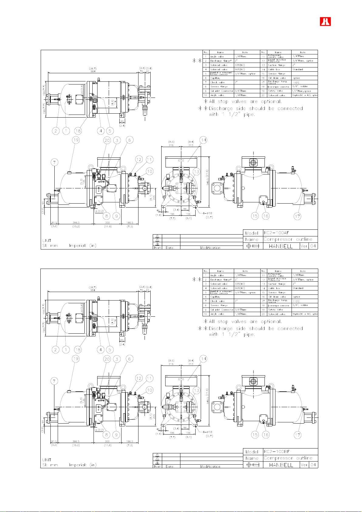
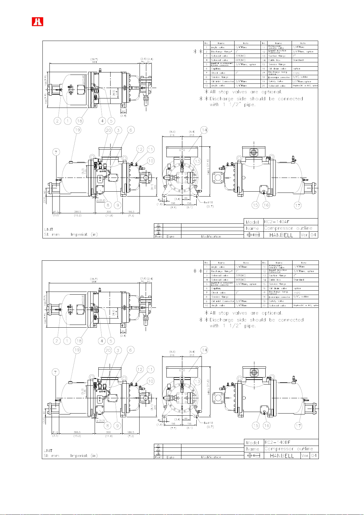
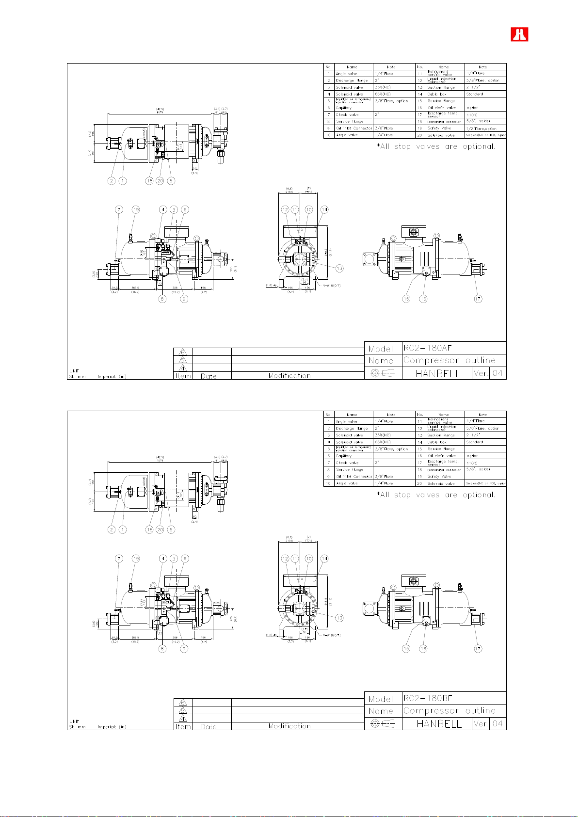
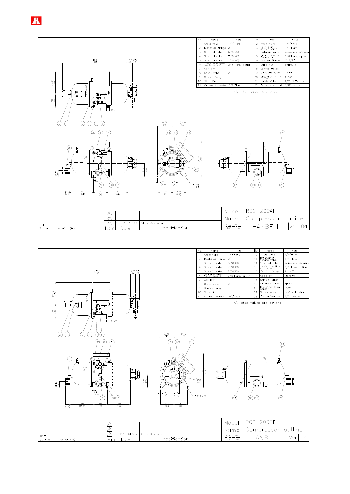
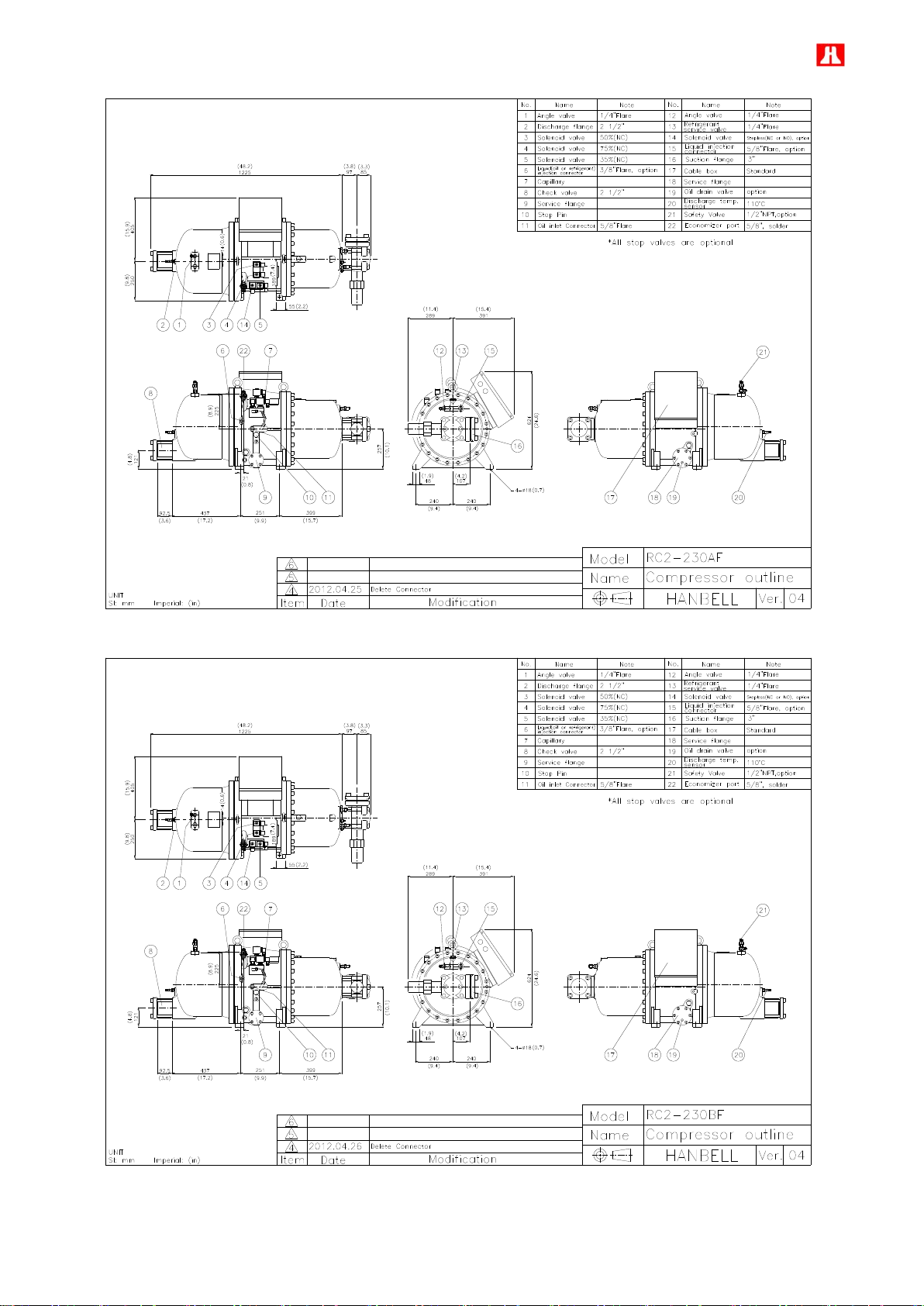
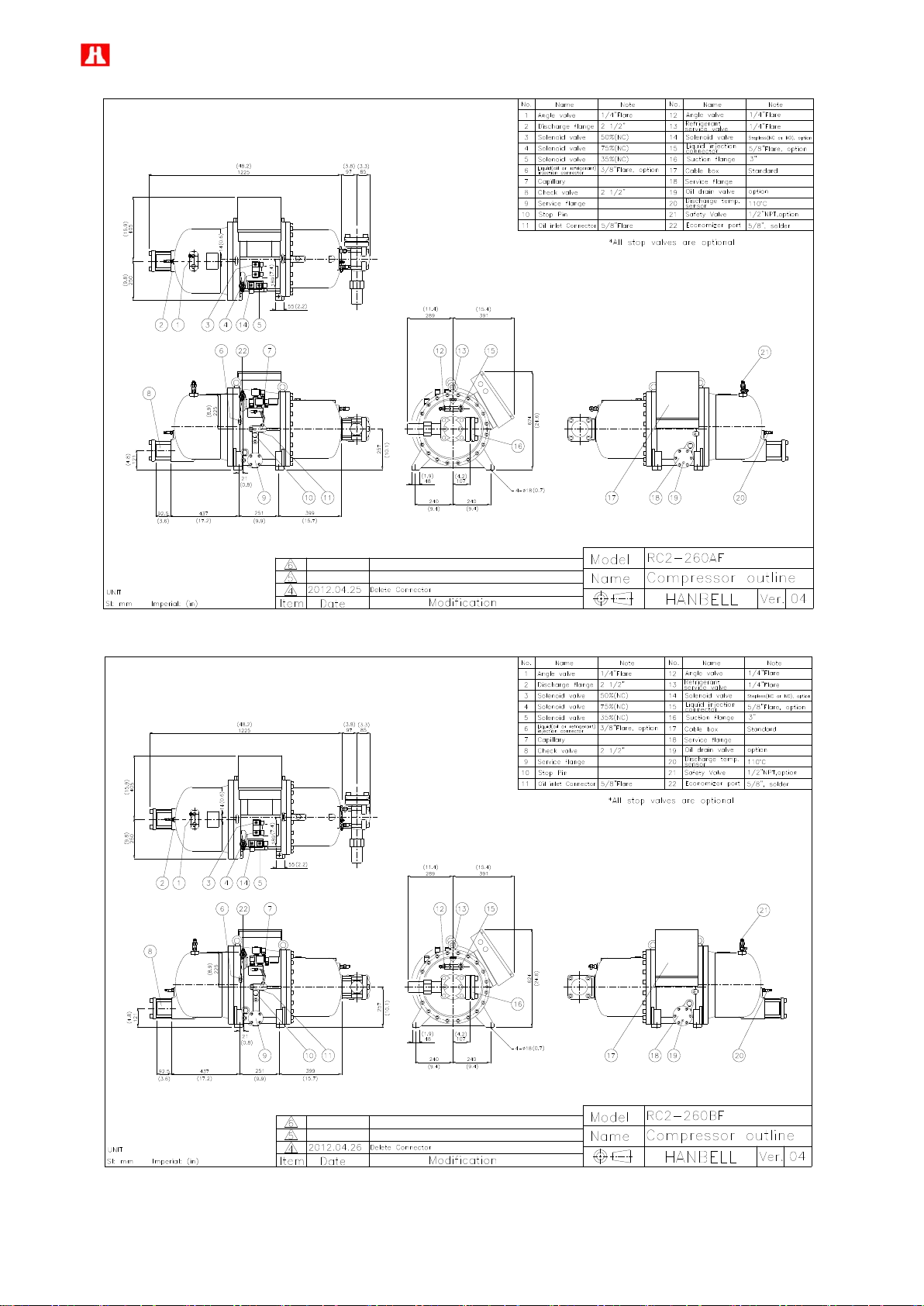
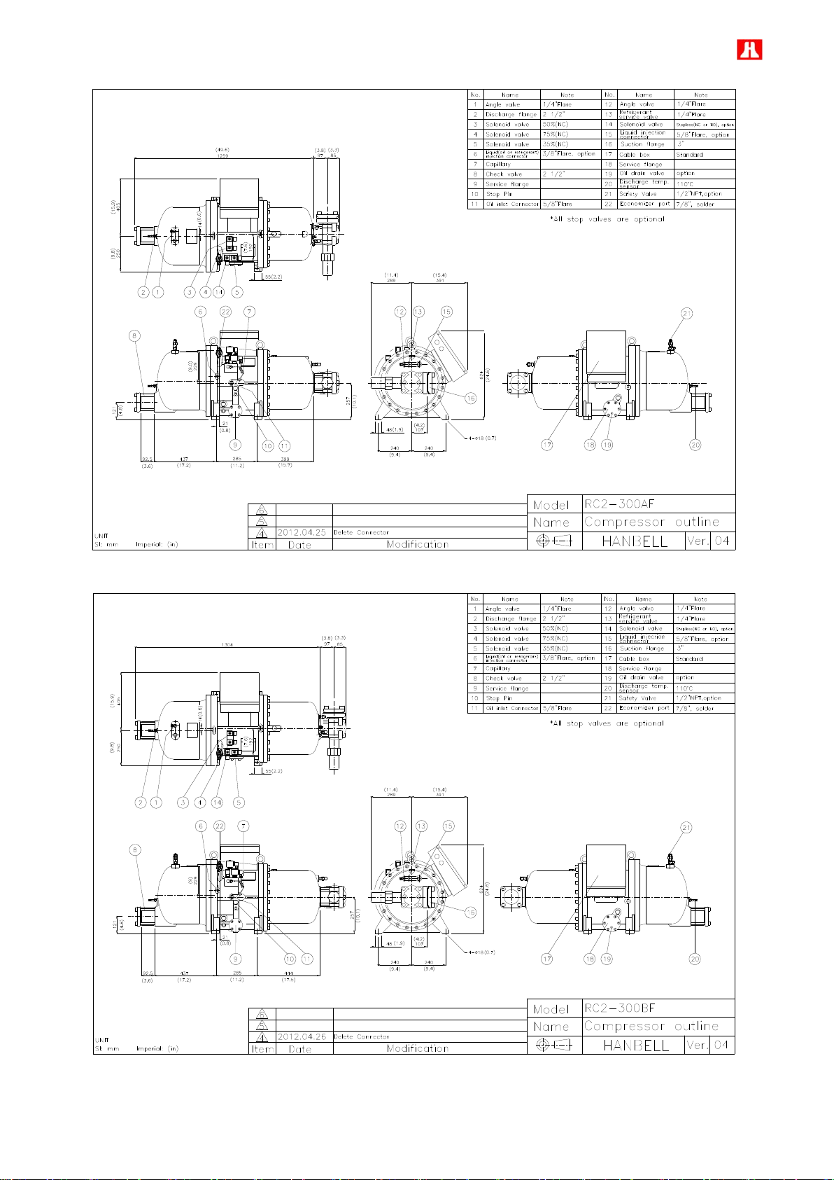
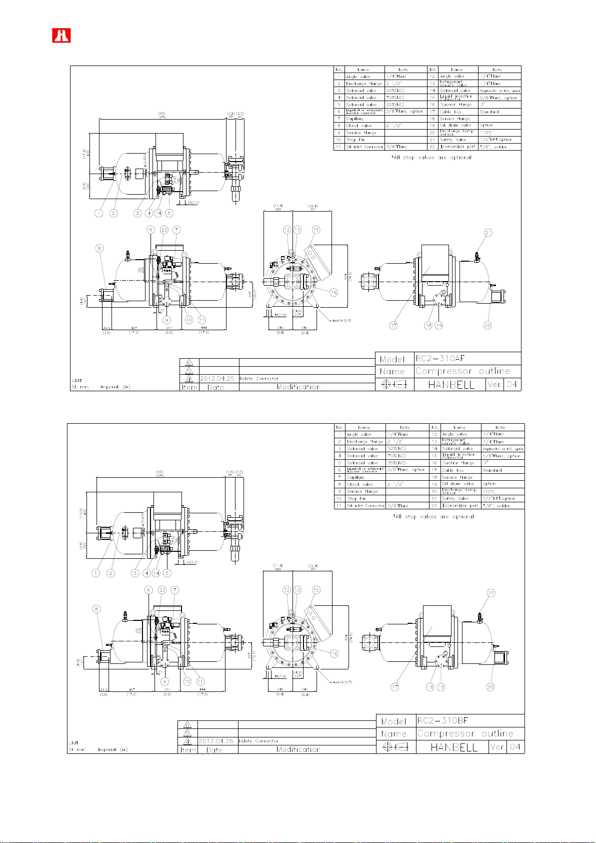
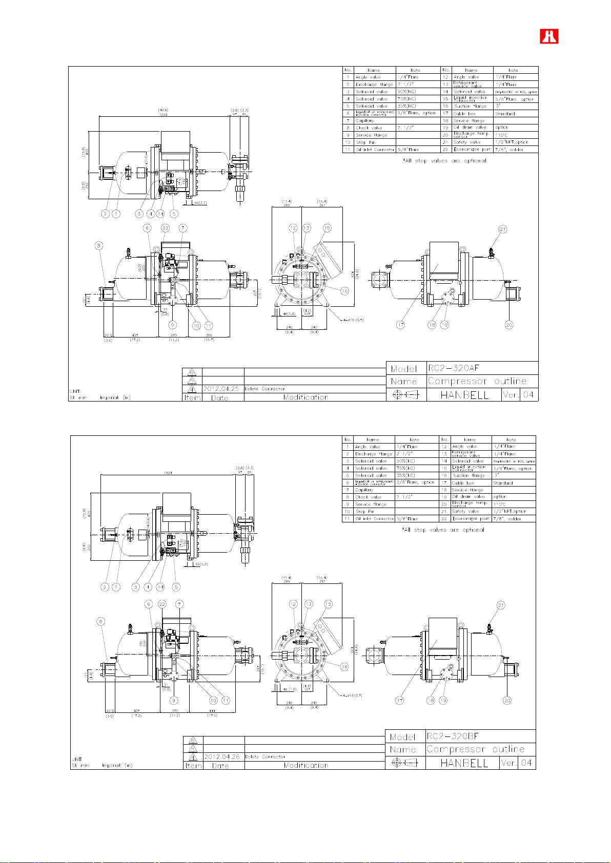
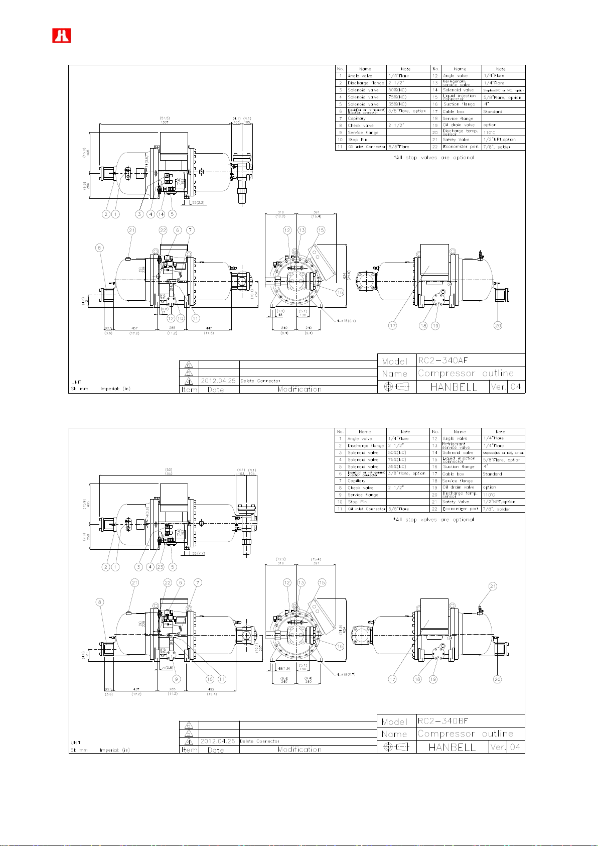
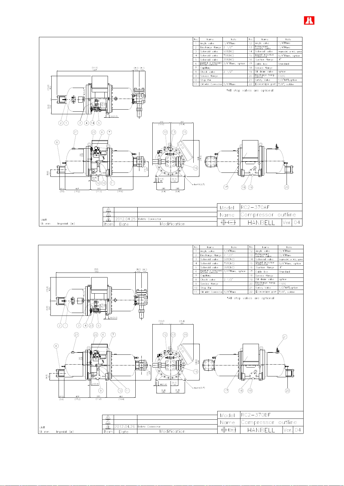
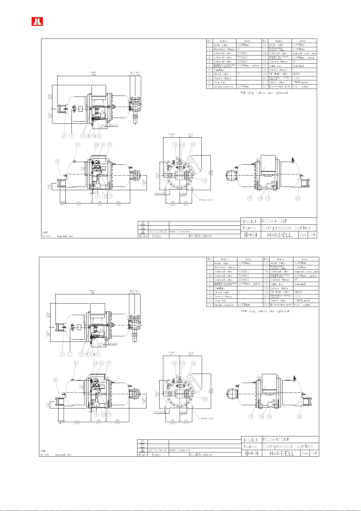
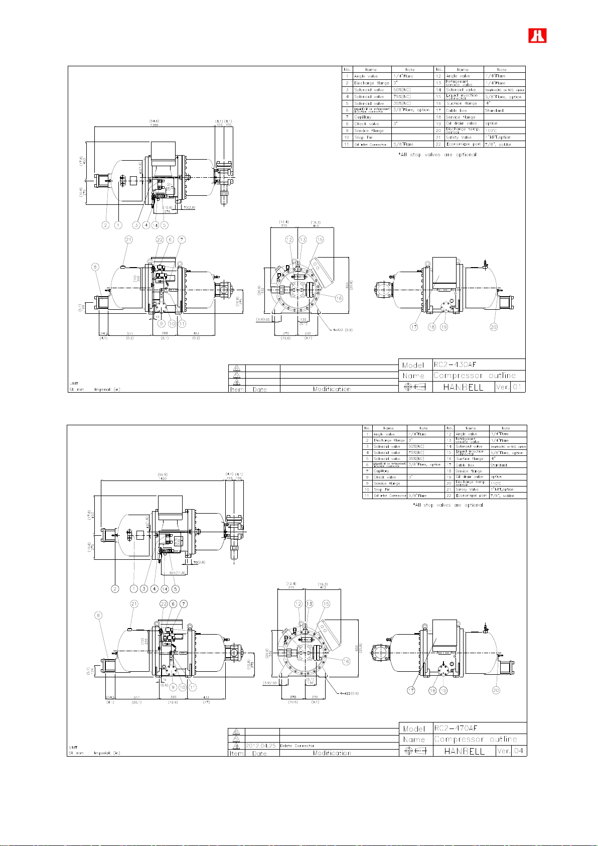
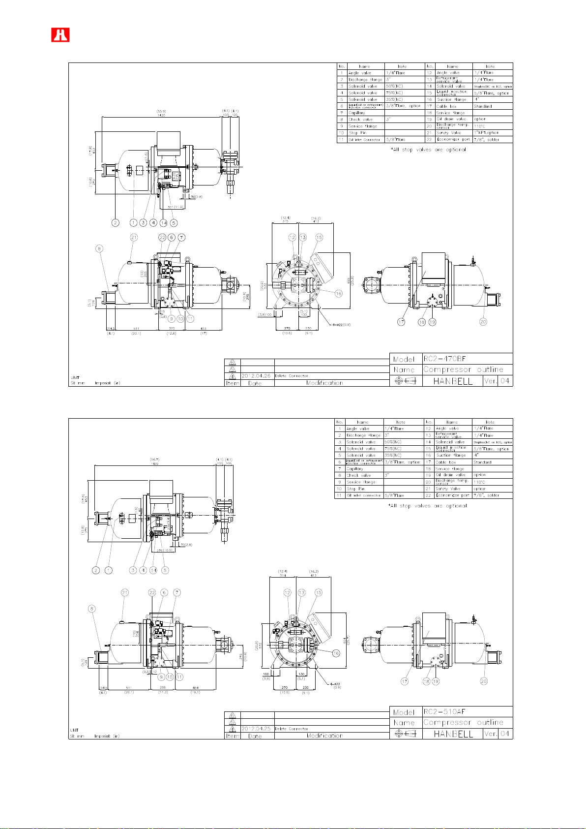
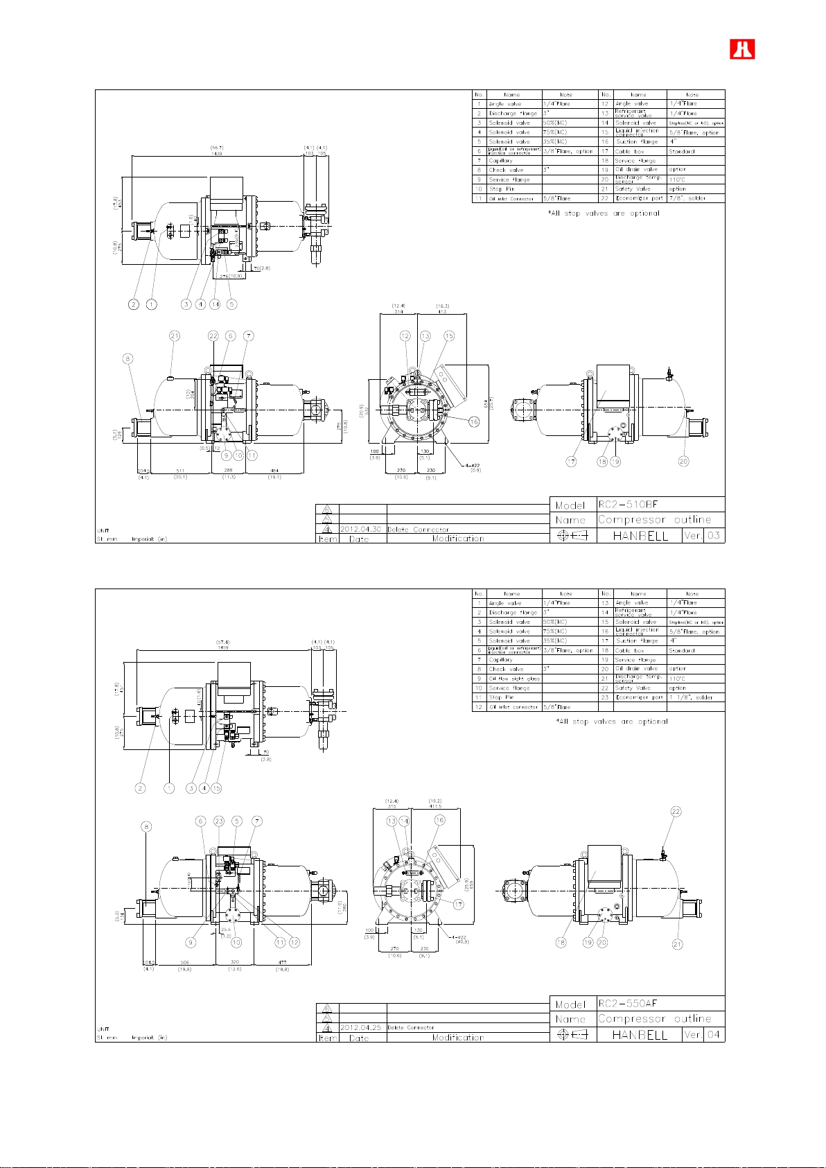
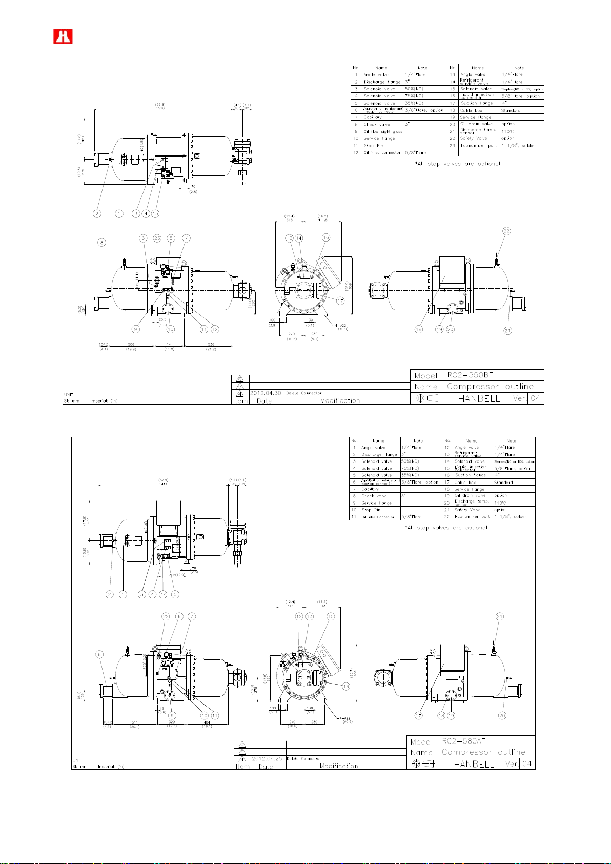
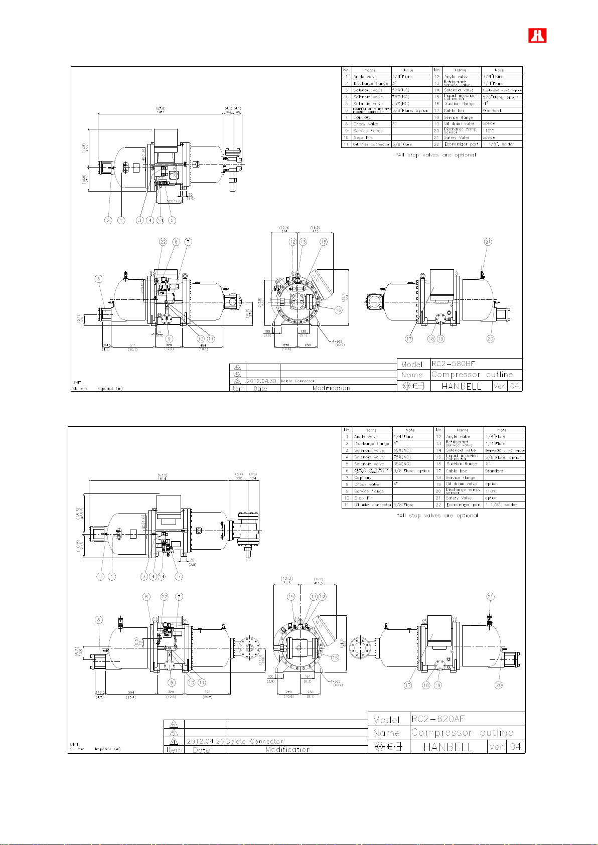
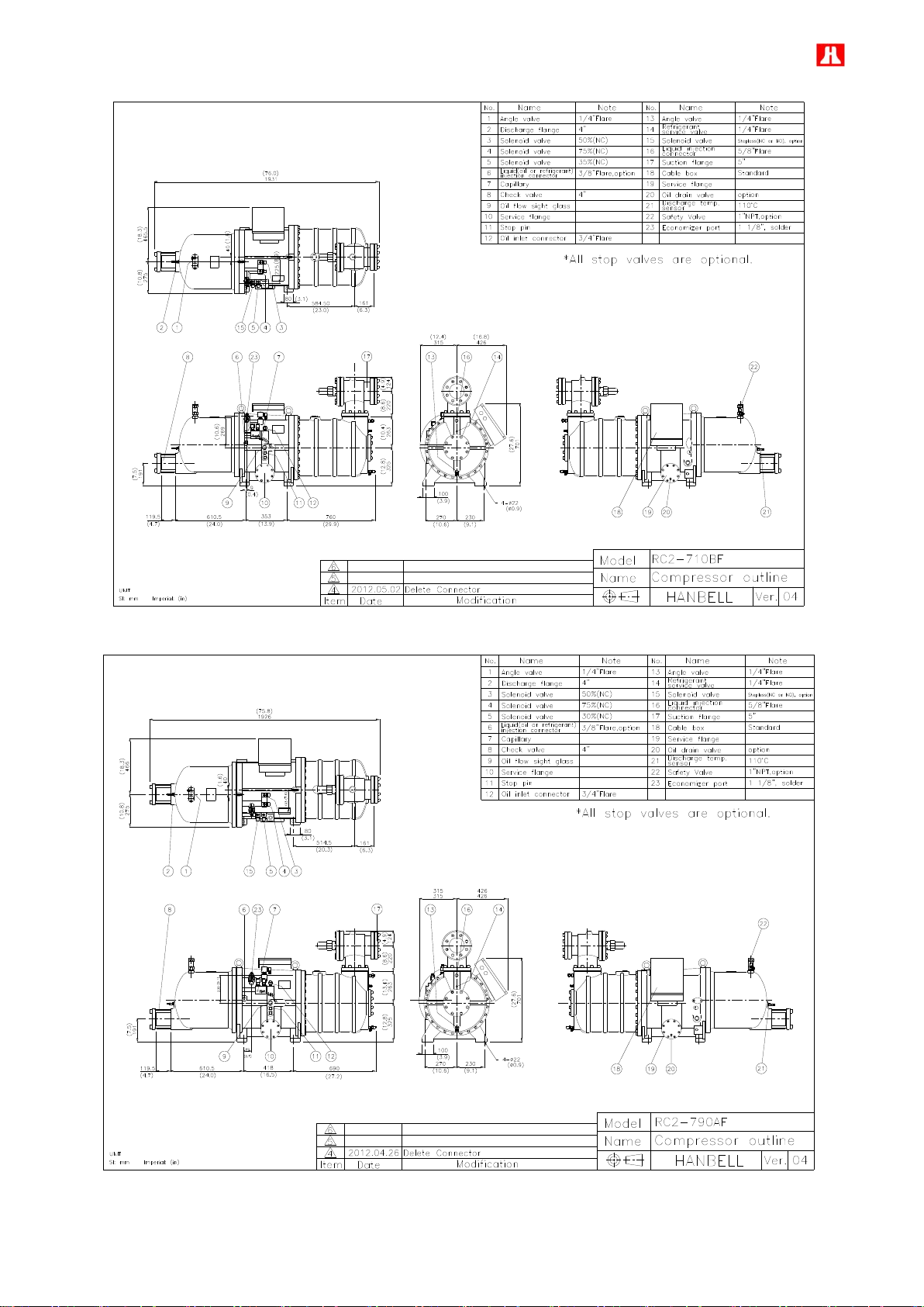
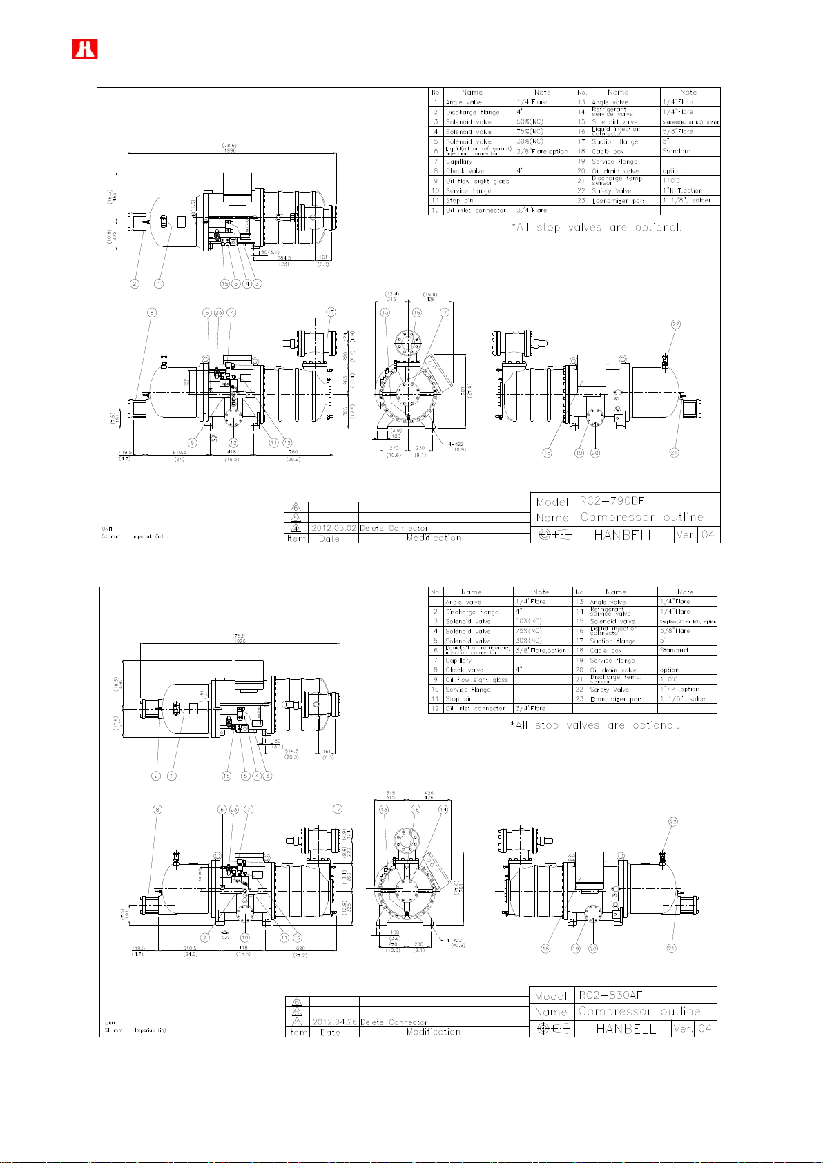
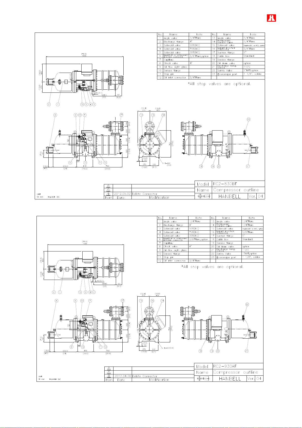
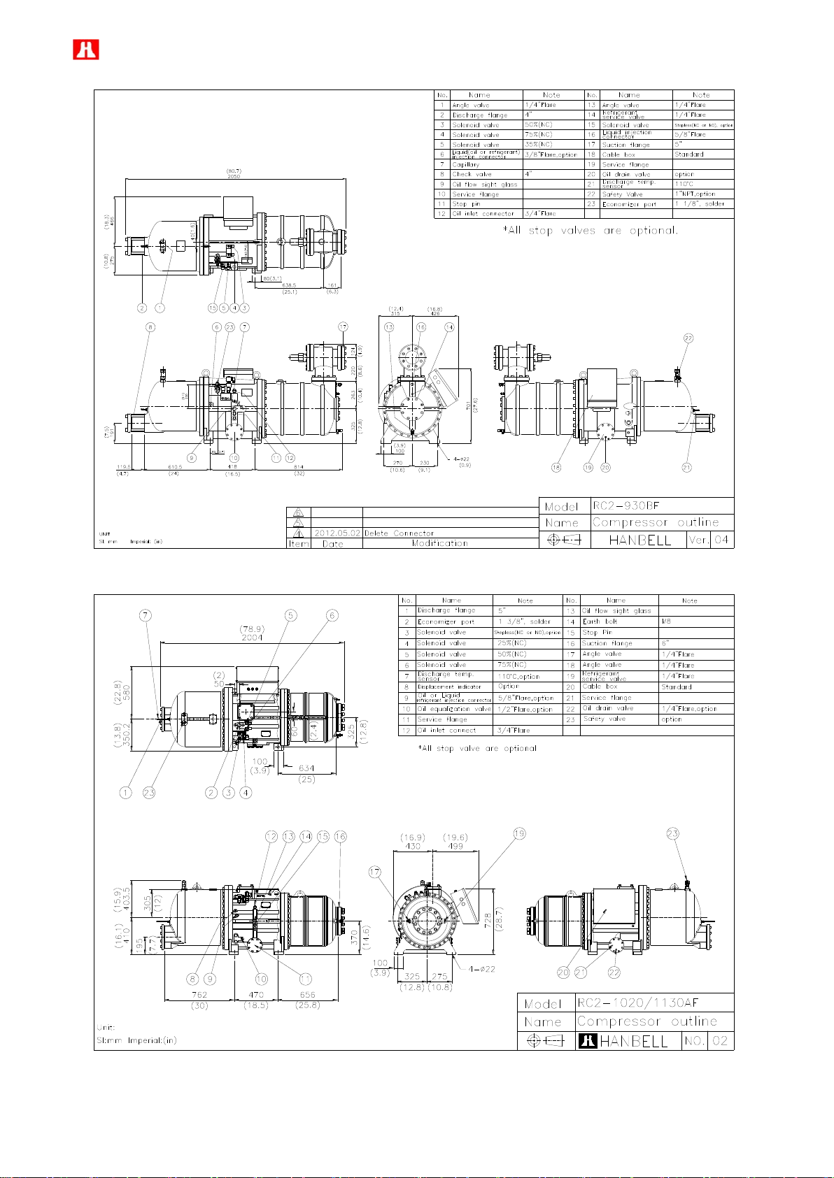
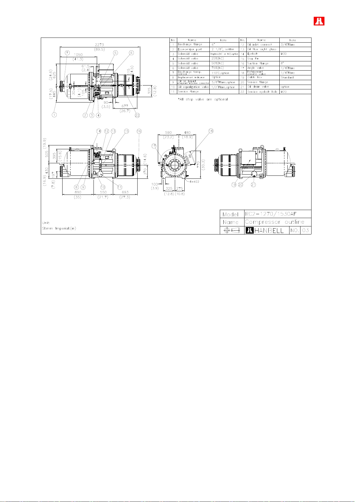
2.2 Compressor outline
6
7
8
9
10
11
12
13
14
15
16
17
18
19
20
21

22
23
24
25
26
27
Note: For RC2-1020BF, RC2-1130BF, RC2-1270BF and RC2-1530BF outline drawing, please refer to those of
RC2-1020AF, RC2-1130AF, RC2-1270AF, and RC2-1530AF
28
No.
Description
No.
Description
1
Compressor casing
15
Discharge bearings
2
Motor casing
16
Discharge fixed ring
3
Discharge casing
17
Disc spring
4
Motor rotor assembly
18
Bearing slot nut
5
Motor stator assembly
19
Male rotor
6
Motor rotor washer
20
Suction bearings
7
Motor rotor spacer ring
21
Suction filter
8
Discharge connect flange
22
Suction flange
9
Piston
23
Discharge flange bushing
10
Piston ring
24
Cable box
11
Piston rod
25
Power bolt
12
Bearing seat cover plate
26
Terminal cover plate
13
Modulation slide valve
27
PTC discharge temperature sensor
14
Slide valve key
No.
Description
No.
Description
1
Compressor casing
17
Disc spring
2
Motor casing
18
Bearing slot nut
3
Discharge casing
19
Male rotor
4
Motor rotor assembly
20
Suction bearings
5
Motor stator assembly
21
Suction bearings
inner/outer spacer ring
6
Motor rotor washer
22
Oil guiding ring
7
Motor rotor spacer ring
23
Suction filter
8
Piston
24
Suction flange
9
Piston ring
25
Cable box
10
Piston rod
26
Power bolt
11
Bearing seat cover plate
27
Thermostat terminals
12
Modulation solenoid
valve
28
Terminal cover plate
13
Modulation slide valve
29
Discharge connect flange
14
Slide valve key
30
Discharge flange bushing
15
Discharge bearings
31
PTC discharge
temperature sensor
16
Discharge fixed ring
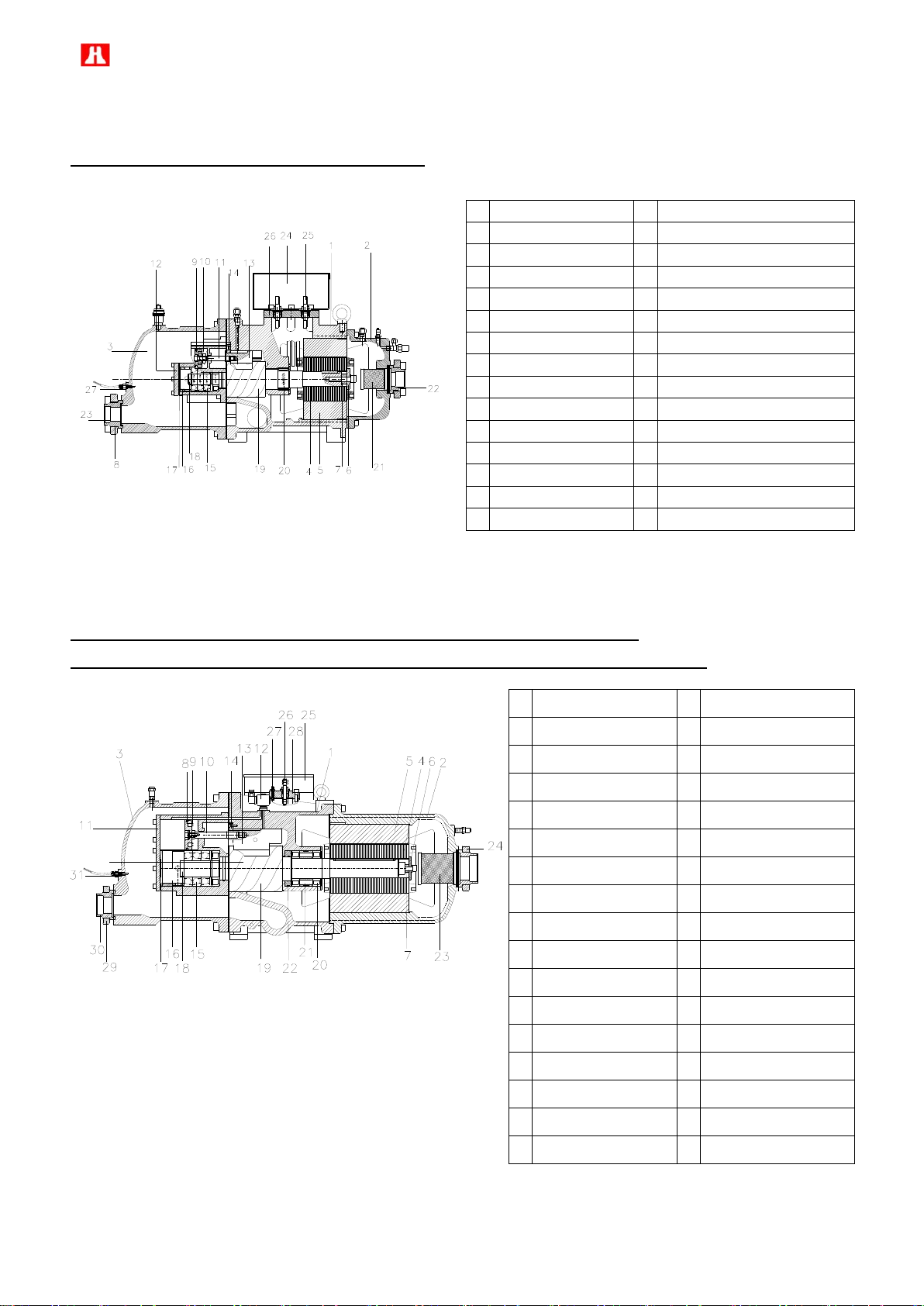
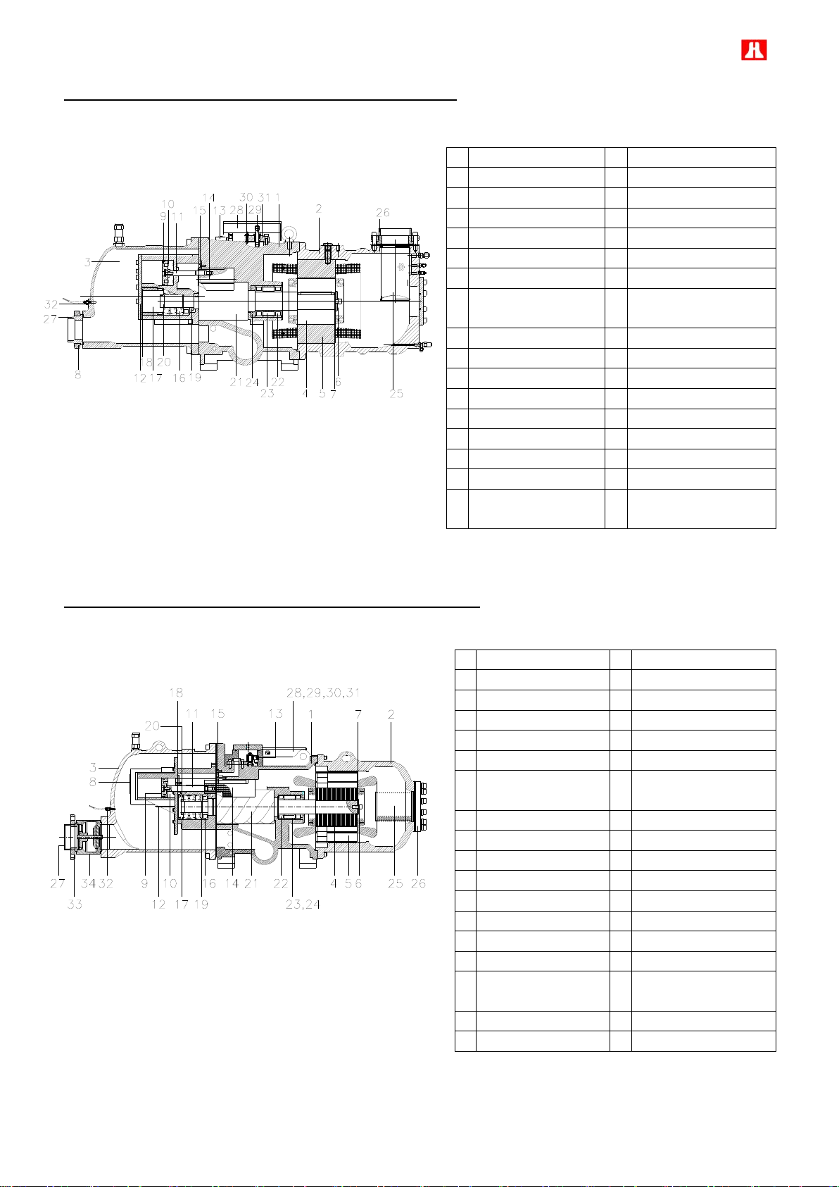
2.3 Compressor construction
RC2-100, RC2-140, RC2-180 F type Construction
RC2-200, RC2-230, RC2-260, RC2-300, RC2-310, RC2-320, RC2-340, RC2-370,
RC2-410, RC2-430, RC2-470, RC2-510, RC2-550, RC2-580, RC2-620 F type Construction
29
RC2-710, RC2-790, RC2-830, RC2-930 F type Construction
No.
Description
No.
Description
1
Compressor casing
17
Discharge fixed ring
2
Motor casing
18
Disc spring
3
Discharge casing
19
α-Balance piston
4
Motor rotor assembly
20
Bearing slot nut
5
Motor stator assembly
21
Male rotor
6
Motor rotor washer
22
Suction bearings
7
Motor rotor spacer ring
23
Suction bearings inner/outer
spacer ring
8
Discharge connect flange
24
Oil guiding ring
9
Piston
25
Suction filter
10
Piston spring
26
Suction flange
11
Piston rod
27
Discharge flange bushing
12
Bearing seat cover plate
28
Cable box
13
Modulation solenoid valve
29
Power bolt
14
Modulation slide valve
30
Thermostat terminals
15
Slide valve key
31
Motor cable cover plate
16
Discharge bearings
32
PTC discharge temperature
sensor
No.
Description
No.
Description
1
Compressor casing
18
Disc spring
2
Motor casing
19
Balance piston
3
Discharge casing
20
Bearing slot nut
4
Motor rotor assembly
21
Male rotor
5
Motor stator assembly
22
Suction bearings
6
Motor rotor washer
23
Suction bearings inner/outer
spacer ring
7
Motor rotor spacer ring
24
Oil guiding ring
8
Muffler
25
Suction filter
9
Piston
26
Suction flange
10
Piston spring
27
Discharge flange bushing
11
Piston rod
28
Cable box
12
Bearing seat cover plate
29
Power bolt
13
Modulation solenoid valve
30
Thermostat terminals
14
Modulation slide valve
31
Motor cable cover plate
15
Slide valve key
32
PTC discharge temperature
sensor
16
Discharge bearings
33
Discharge connect flange
17
Discharge fixed ring
34
Check valve
RC2-1020, RC2-1130, RC2-1270, RC2-1530 F type Construction
 Loading...