

Page 1

0
CONTENTS
1. Compressor’s characteristics ............................................................................................................................. 2
2. Compressor specification .................................................................................................................................... 3
2.1 Design specification .................................................................................................................................... 3
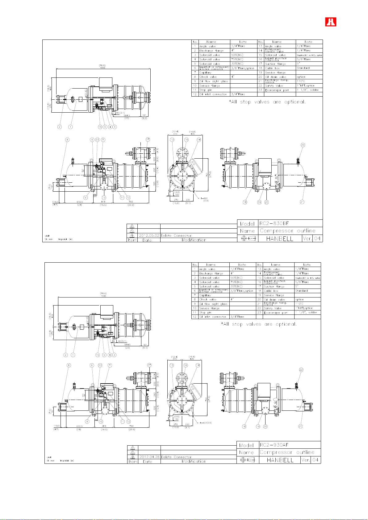
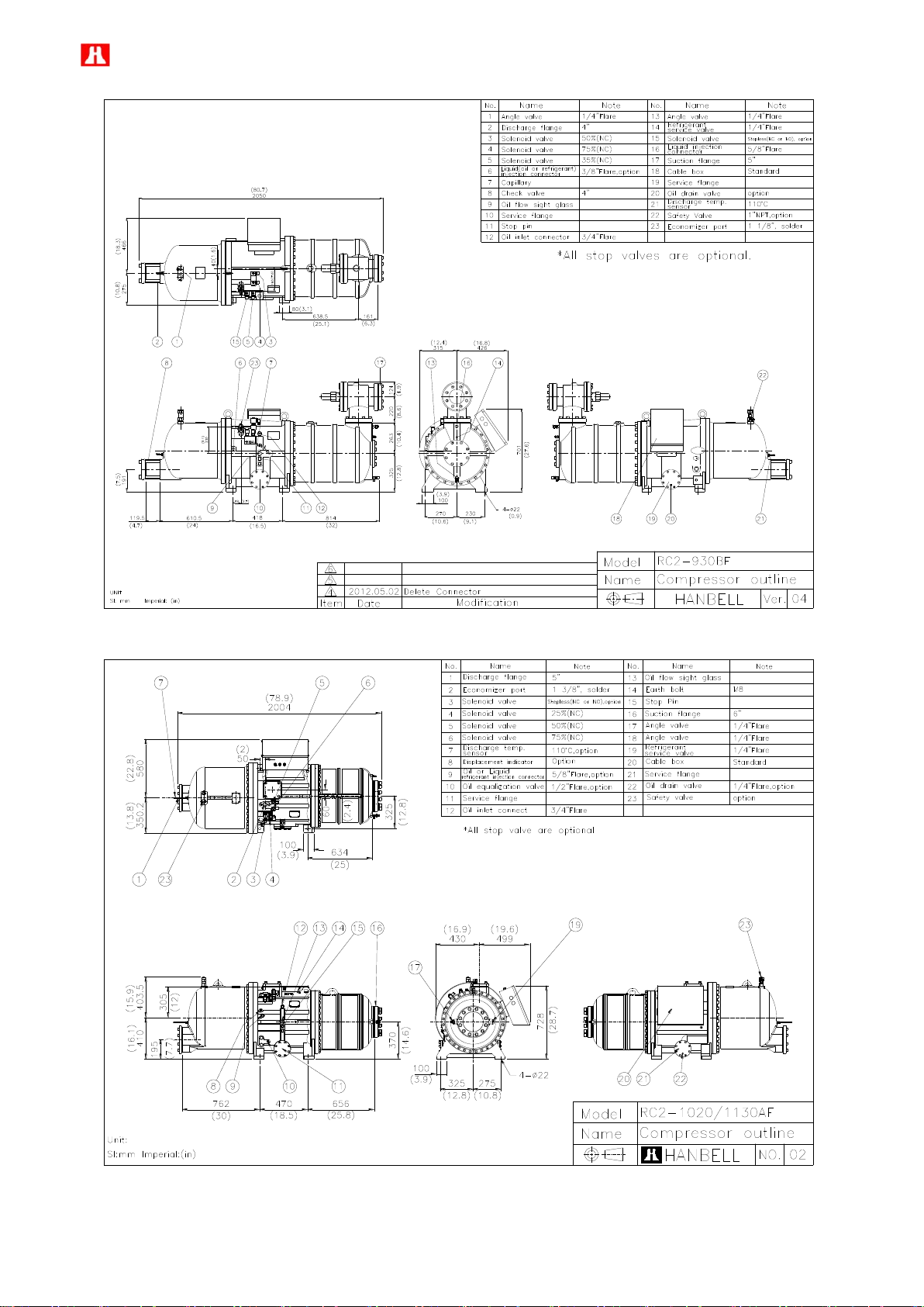
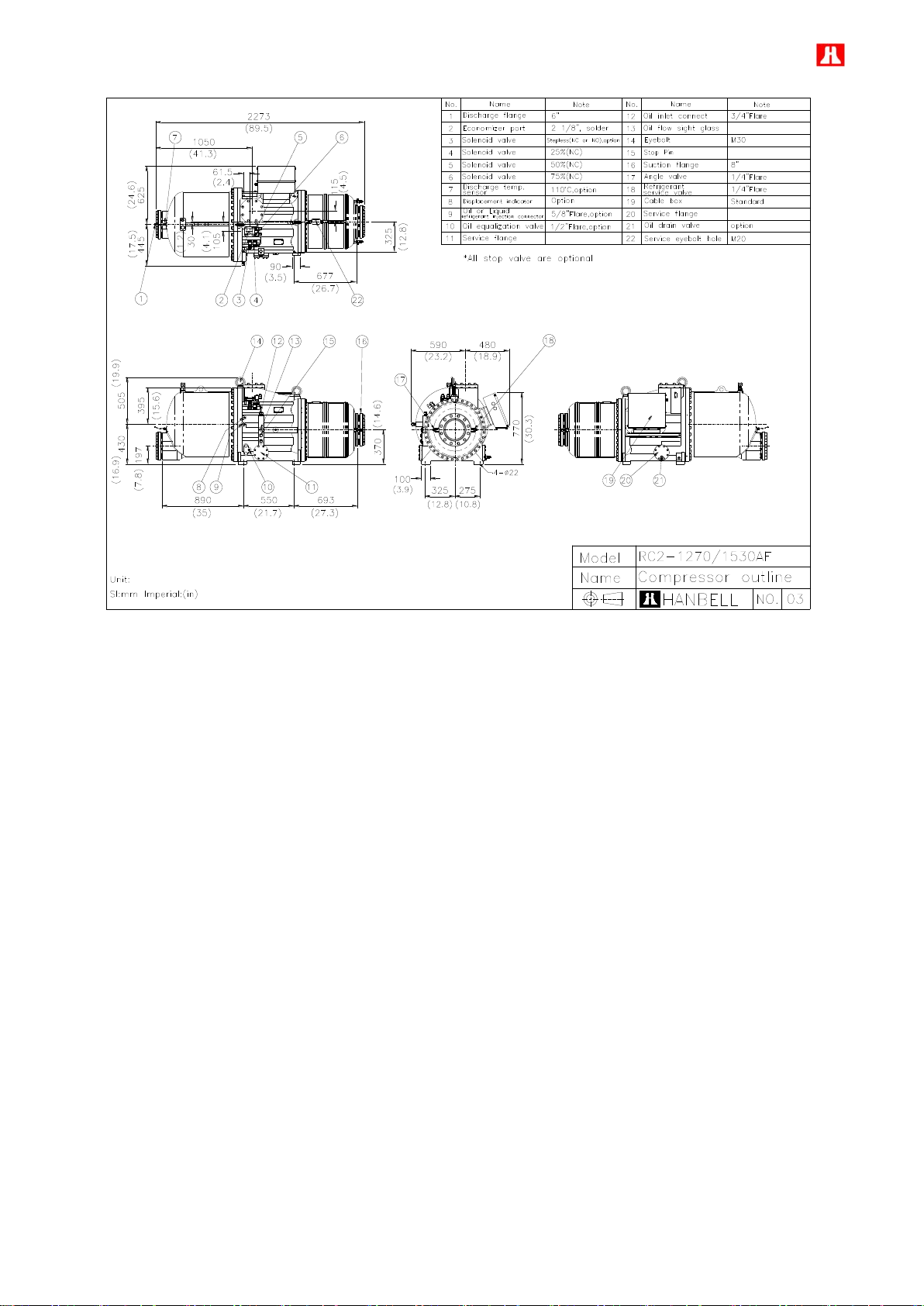
2.2 Compressor outline ..................................................................................................................................... 5
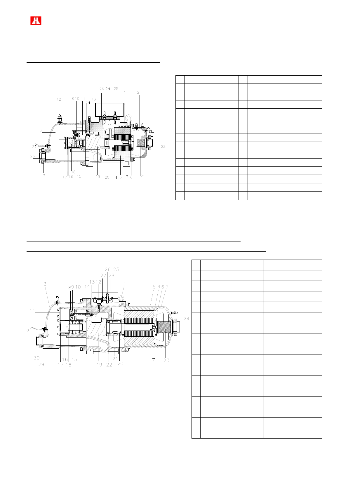
2.3 Compressor construction ......................................................................................................................... 28
2.4 Capacity control system ........................................................................................................................... 30
2.5 Compressor application limits ................................................................................................................. 33
2.6 Compressor design feature ...................................................................................................................... 35
2.7 MCC and LRA ............................................................................................................................................. 37
3. Compressor handling and Installation ............................................................................................................. 41
3.1 Compressor handling ............................................................................................................................... 41
3.2 Mounting the compressor ........................................................................................................................ 41
4. Lubricant .............................................................................................................................................................. 64
4.1 Pre-cautions in changing of oil ................................................................................................................ 64
4.2 Changing of oil .......................................................................................................................................... 65
4.3 Lubricants table ......................................................................................................................................... 66
5. Electrical data and design ................................................................................................................................. 67
5.1 Motor design .............................................................................................................................................. 67
5.2 Compressor protection devices .............................................................................................................. 69
5.3 Power supply ............................................................................................................................................. 69
5.4 Selection of magnetic contactor .............................................................................................................. 71
5.5 Grounding .................................................................................................................................................. 71
6. Compressors accessories ................................................................................................................................. 72
6.1 Compressors standard and optional accessories ................................................................................. 72
6.2 Description of accessories ....................................................................................................................... 73
7. Operation and trouble shooting ........................................................................................................................ 87
7.1 Compressor start-up ................................................................................................................................. 87
7.2 System adjustment .................................................................................................................................... 89
7.3 Compressor stop ....................................................................................................................................... 91
7.4 Troubleshooting ........................................................................................................................................ 92
7.5 Compressor checking list......................................................................................................................... 95
8. System applications ........................................................................................................................................... 96
8.1 General application ................................................................................................................................... 96
8.2 Economizer application .......................................................................................................................... 109
8.3 Important notice to compressor application ........................................................................................ 112
8.4 Example of installation ........................................................................................................................... 113
Appendix 1. Compressor noise level .................................................................................................................. 116
Page 2

1
Introduction
The Hanbell RC2-F series semi-hermetic twin-screw compressor inherits all the quality and experience of our
RC2 series compressor. The RC2-F series compressor is developed especially for application with Freon in
flooded system or refrigeration field. With a built-in high operating load design and advanced 5 to 6 Patented
Screw Rotor Profile, each compressor has high efficiency and reliability in all operating condition. Each unit is
carefully manufactured and inspected by high precision THREAD SCREW ROTOR GRINDING MACHINE, CNC
MACHINING CENTER, and 3-D COORDINATE MEASURING MACHINE. Each compressor at HANBELL also
follows the ISO 9001 certification quality system which assures the best quality control and production process to
customers. RC2-F series compressor has 27 models RC2-100~RC2-1530, with displacement (50/60Hz) from 98
/ 1 18 m3/hr to 1539 / 1847 m3/hr.
The RC2-F series compressors use high quality bearings which resulted in longer bearing life compare to
competitors. These bearings provide strong support to screw rotors especially for the heavy duty application.
Oil/Refrigerant injection port can be utilized when external cooling is needed at chamber. This can keep the
compression chamber at proper discharge temperature and ensures sufficient oil viscosity for moving parts
lubrication. Economizer port can be used to reach higher cooling capacity and working efficiency especially at high
pressure ratio working condition or at very low evaporating temperature. All these new designs guarantee that the
compressor has the best reliability, longest bearing life and easiest regular maintenance work.
This Technical Manual contains all basic information about dimensions, handling, installation, operation, trouble
shooting, and system application. It is highly recommended that the content of this manual should be read carefully
prior to handling, installing, and operating the RC2-F compressor in order to prevent any unwanted damage on it.
For any technical issue related to RC2-F series compressor, please contact HANBELL or local distributors/agents
for more information and assistance.
Page 3

2
1. Compressor’s characteristics
1-1 Multi country (Taiwan, China, USA, England) patented high efficiency 5 to 6 asymmetrical rotor profile.
1-2 Precise volume control system
Steps or continuous capacity control system are available.
1-3 Economizer applications
Economizer port is a standard accessory for RC2-F series screw compressor.
Floating type medium pressure (Economizer returned pressure) design, no matter if compressor work at full
load or partial load condition, always can track the best medium pressure value, it means economizer could
develop the maximum efficiency during the operation.
1-4 Applicable with:R-134a, R-407C, R22, R404A, R507A.
1-5 Resistant to high load condition with long life bearing design
1-6 PTC temperature thermistor for the protection of
(1) High motor coil temperature
(2) High discharge temperature
(3) High oil temperature (optional)
1-7 Low vibration and low noise.
1-8 High efficiency oil separator, low-pressure drop, external connection.
Page 4

3
2. Compressor specification
MODEL
COMPRESSOR
MOTOR
Hydrostatic Pressure
Test
Weight
Displacement 60 /
50Hz
Rated
Speed
VI
Cap. Control (%)
Type
Nominal
Hp
Starting
Voltage (V)
Insulation
Protection
m3/hr
60 / 50Hz
STEP
STEPLESS
60Hz
50Hz
60Hz
50Hz
Kg/cm2G
kg
RC2-100AF
118/98
3550/2950
2.2
2.6
3.0
3.5
4.8
33, 66, 100
33~100
3 Phase, 2 Pole, Squirrel Cage, Induction Motor
23
19
Y-△
PWS
DOL
208
220
230
380
440
460
480
575
380
400
415
Class F
PTC Protection
42
260
RC2-140AF
165/137
33, 66, 100
33~100
32
26
265
RC2-180AF
216/180
33, 66, 100
33~100
42
35
365
RC2-200AF
233/193
25, 50, 75, 100
25~100
45
37
405
RC2-230AF
277/230
35, 50, 75, 100
35~100
53
44
530
RC2-260AF
309/257
25, 50, 75, 100
25~100
59
49
535
RC2-300AF
352/293
25, 50, 75, 100
25~100
67
56
580
RC2-310AF
371/308
35, 50, 75, 100
35~100
71
59
565
RC2-320AF
384/320
25, 50, 75, 100
25~100
72
60
595
RC2-340AF
407/339
35, 50, 75, 100
35~100
77
64
600
RC2-370AF
440/366
35, 50, 75, 100
35~100
84
70
610
RC2-410AF
490/407
25, 50, 75, 100
25~100
93
78
380
440
460
480
575
730
RC2-430AF
512/425
25, 50, 75, 100
25~100
100
84
735
RC2-470AF
567/471
25, 50, 75, 100
25~100
108
90
800
RC2-510AF
611/508
35, 50, 75, 100
35~100
117
98
760
RC2-550AF
660/549
25, 50, 75, 100
25~100
126
105
820
RC2-580AF
702/583
35, 50, 75, 100
35~100
131
109
805
RC2-620AF
745/619
35, 50, 75, 100
35~100
137
114
Y-△
DOL
850
RC2-710AF
858/713
35, 50, 75, 100
35~100
158
131
1050
RC2-790AF
952/791
30, 50, 75, 100
30~100
175
146
1140
RC2-830AF
993/825
30, 50, 75, 100
30~100
183
152
1150
RC2-930AF
1117/929
35, 50, 75, 100
35~100
212
176
1180
RC2-1020AF
1223/1017
25, 50, 75, 100
25~100
227
189
1500
RC2-1130AF
1350/1122
25, 50, 75, 100
25~100
248
206
1520
RC2-1270AF
1521/1268
25, 50, 75, 100
25~100
286
238
2100
RC2-1530AF
1847/1539
25, 50, 75, 100
25~100
331
275
2200
2.1 Design specification
a. RC2-AF
Page 5
4
MODEL
COMPRESSOR
MOTOR
Hydrostatic
Pressure Test
Weight
Displacement 60 /
50Hz
Rated
Speed
VI
Cap. Control (%)
Type
Nominal
Hp
Starting-Up
Voltage (V)
Insulation
Protection
m3/hr
60 / 50Hz
STEP
STEPLESS
60Hz
50Hz
60Hz
50Hz
Kg/cm2G
kg
RC2-100BF
118/98
3550/2950
2.2
2.6
3.0
3.5
4.8
33, 66, 100
33~100
3 Phase, 2 Pole, Squirrel Cage, Induction Motor
38
31
Y-△
PWS
DOL
208
220
230
380
440
460
480
575
380
400
415
Class F
PTC Protection
42
265
RC2-140BF
165/137
33, 66, 100
33~100
50
41
270
RC2-180BF
216/180
33, 66, 100
33~100
66
55
390
RC2-200BF
233/193
25, 50, 75, 100
25~100
70
58
415
RC2-230AF
277/230
35, 50, 75, 100
35~100
53
44
535
RC2-260BF
309/257
25, 50, 75, 100
25~100
90
75
540
RC2-300BF
352/293
25, 50, 75, 100
25~100
107
89
600
RC2-310BF
371/308
35, 50, 75, 100
35~100
110
91
570
RC2-320BF
384/320
25, 50, 75, 100
25~100
114
94
600
RC2-340BF
407/339
35, 50, 75, 100
35~100
121
101
620
RC2-370BF
440/366
35, 50, 75, 100
35~100
130
108
640
RC2-410BF
490/407
25, 50, 75, 100
25~100
146
121
380
440
460
480
575
740
RC2-470BF
567/471
25, 50, 75, 100
25~100
170
141
810
RC2-510BF
611/508
35, 50, 75, 100
35~100
183
152
780
RC2-550BF
660/549
25, 50, 75, 100
25~100
195
162
850
RC2-580BF
702/583
35, 50, 75, 100
35~100
210
175
840
RC2-620BF
745/619
35, 50, 75, 100
35~100
220
183
Y-△
DOL
880
RC2-710BF
858/713
35, 50, 75, 100
35~100
250
208
1080
RC2-790BF
952/791
30, 50, 75, 100
30~100
276
230
1180
RC2-830BF
993/825
30, 50, 75, 100
30~100
290
234
1215
RC2-930BF
1117/929
35, 50, 75, 100
35~100
334
278
1240
RC2-1020BF
1223/1017
25, 50, 75, 100
25~100
357
297
1540
RC2-1130BF
1350/1122
25, 50, 75, 100
25~100
393
327
1560
RC2-1270BF
1521/1268
25, 50, 75, 100
25~100
471
392
2200
RC2-1530BF
1847/1539
25, 50, 75, 100
25~100
534
443
2300
b. RC2-BF
Nominal Horse Power:
All above Nominal Hp are not equal to the maximum compressors Hp; Please refer to Hanbell selection software’s
output for the rated current, Maximum Continuous Current-M.C.C according to various working condition while
selecting the contactor, cable, fuse and wire, etc…
Page 6
5
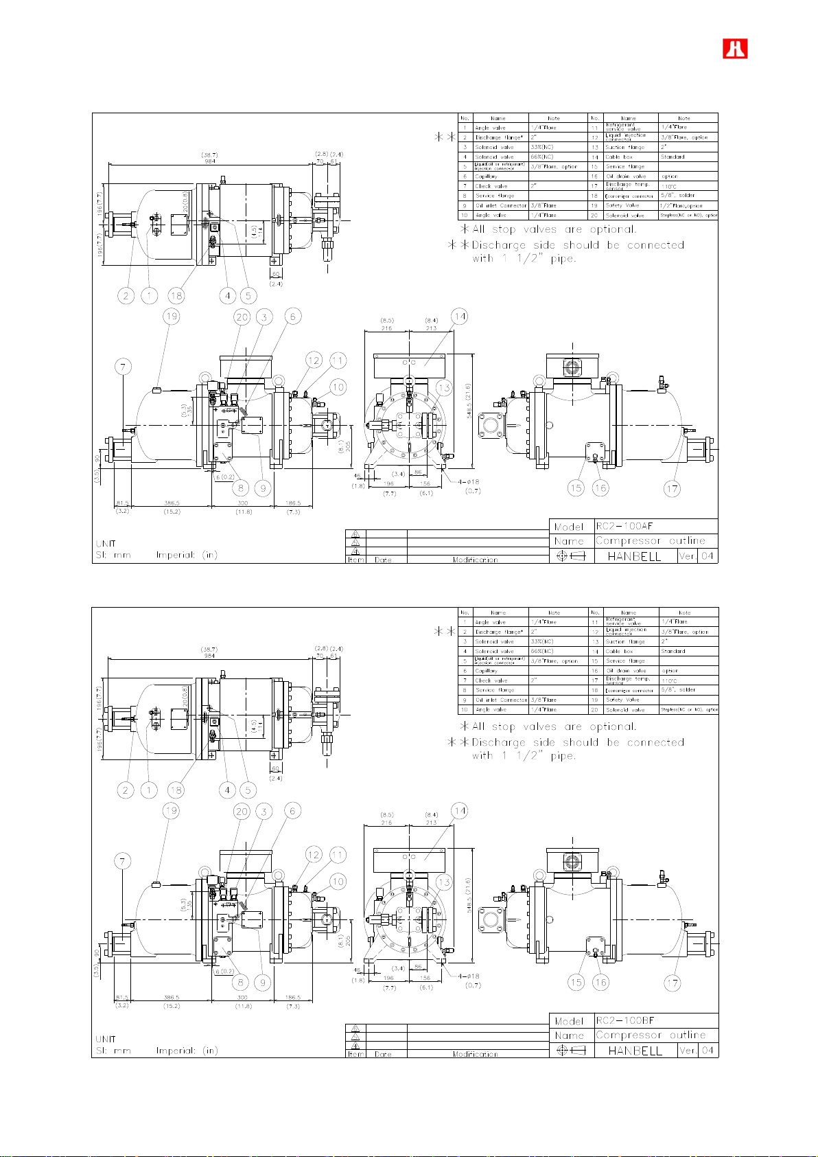
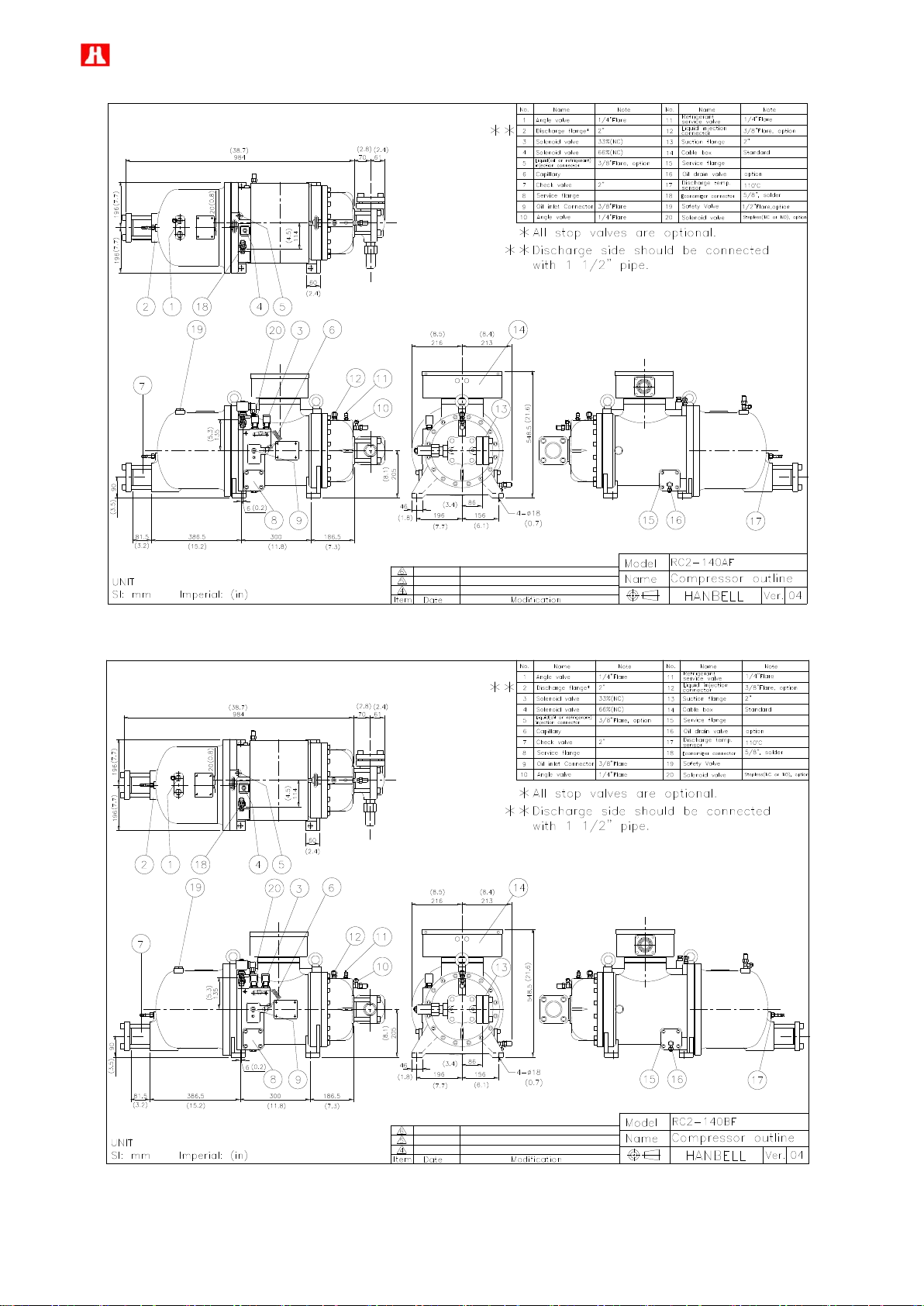
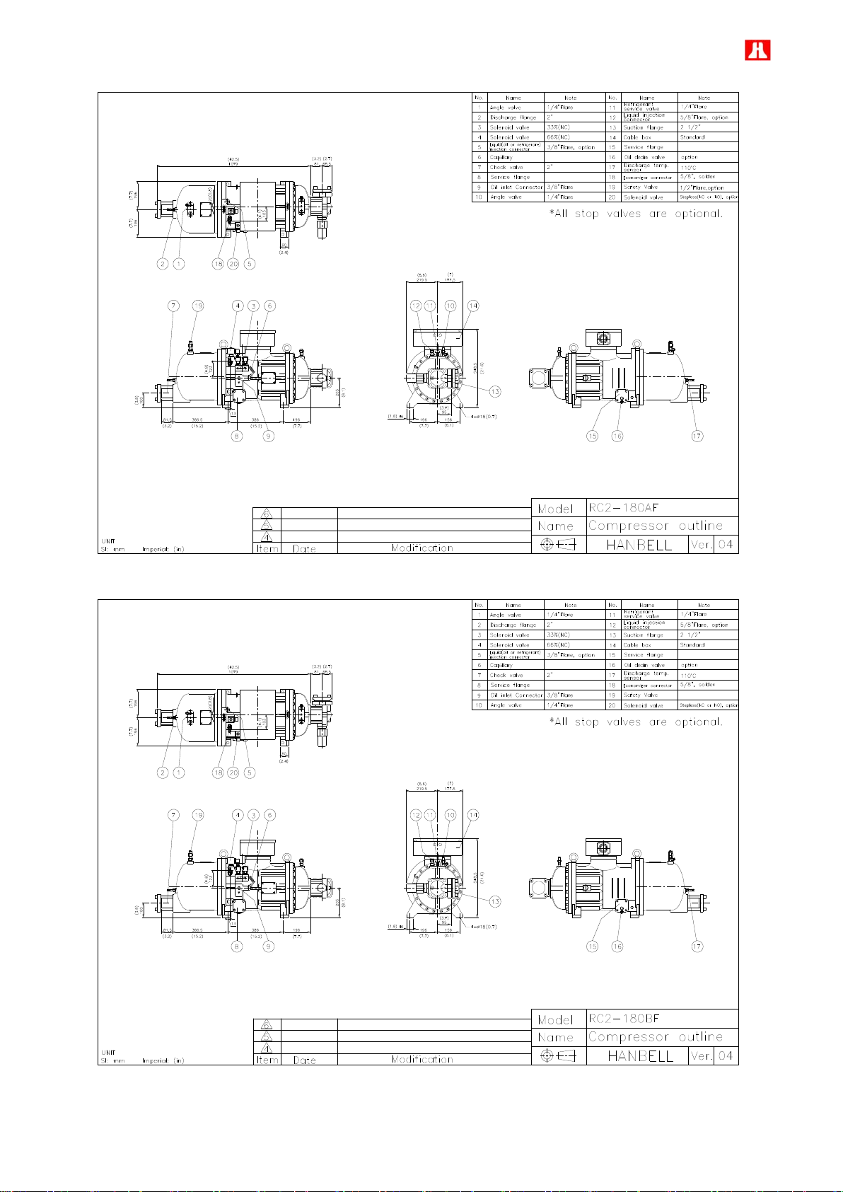
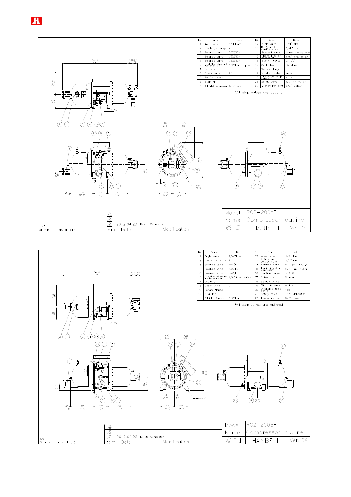
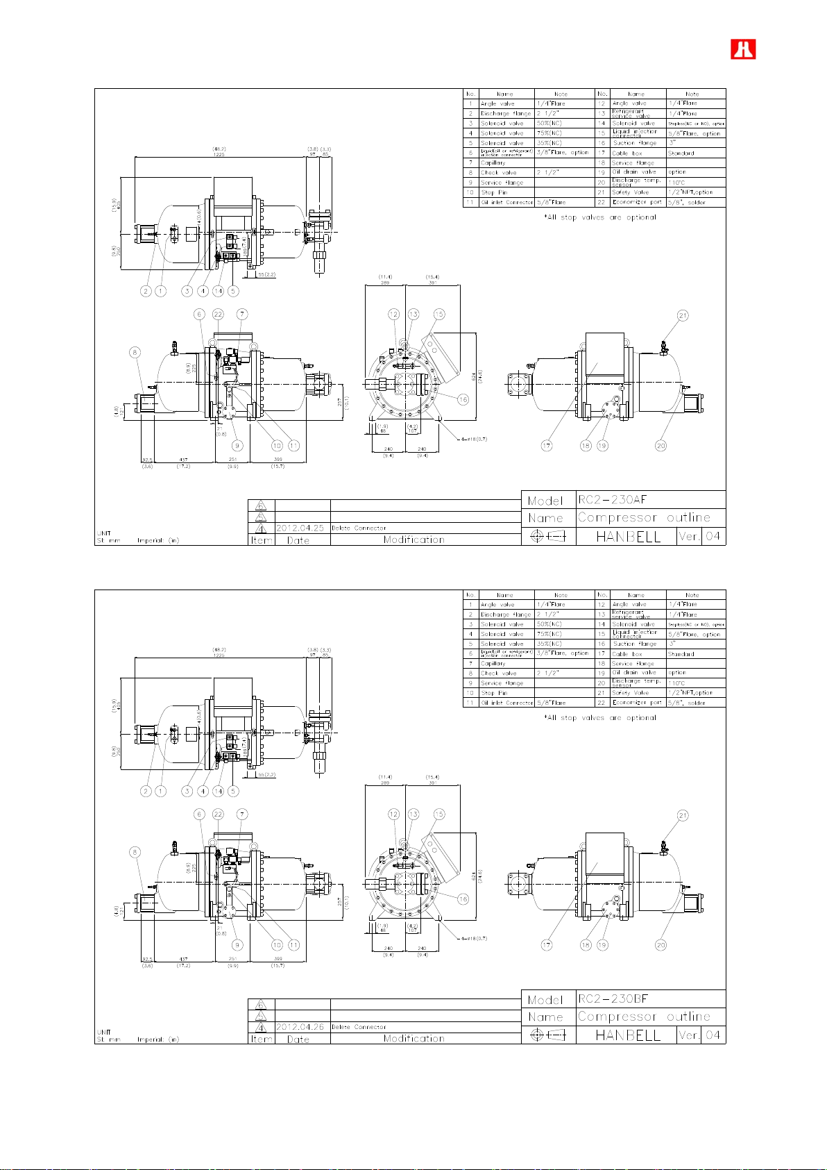
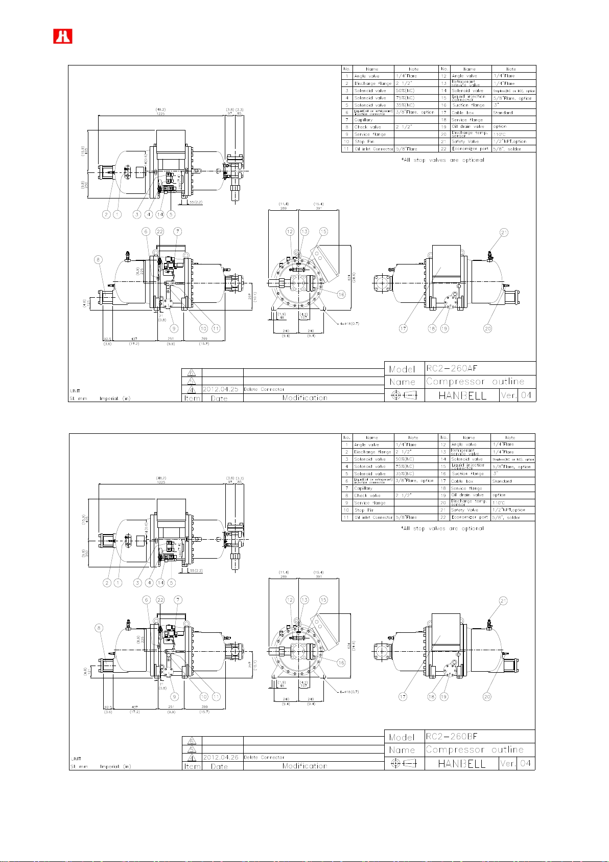
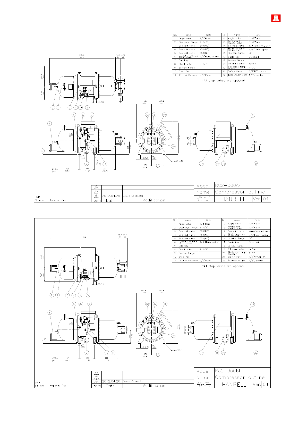
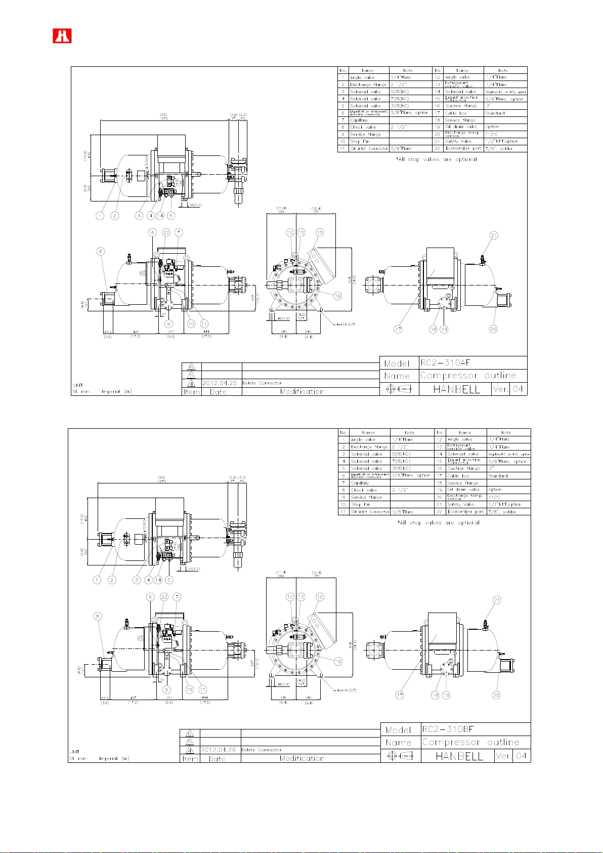
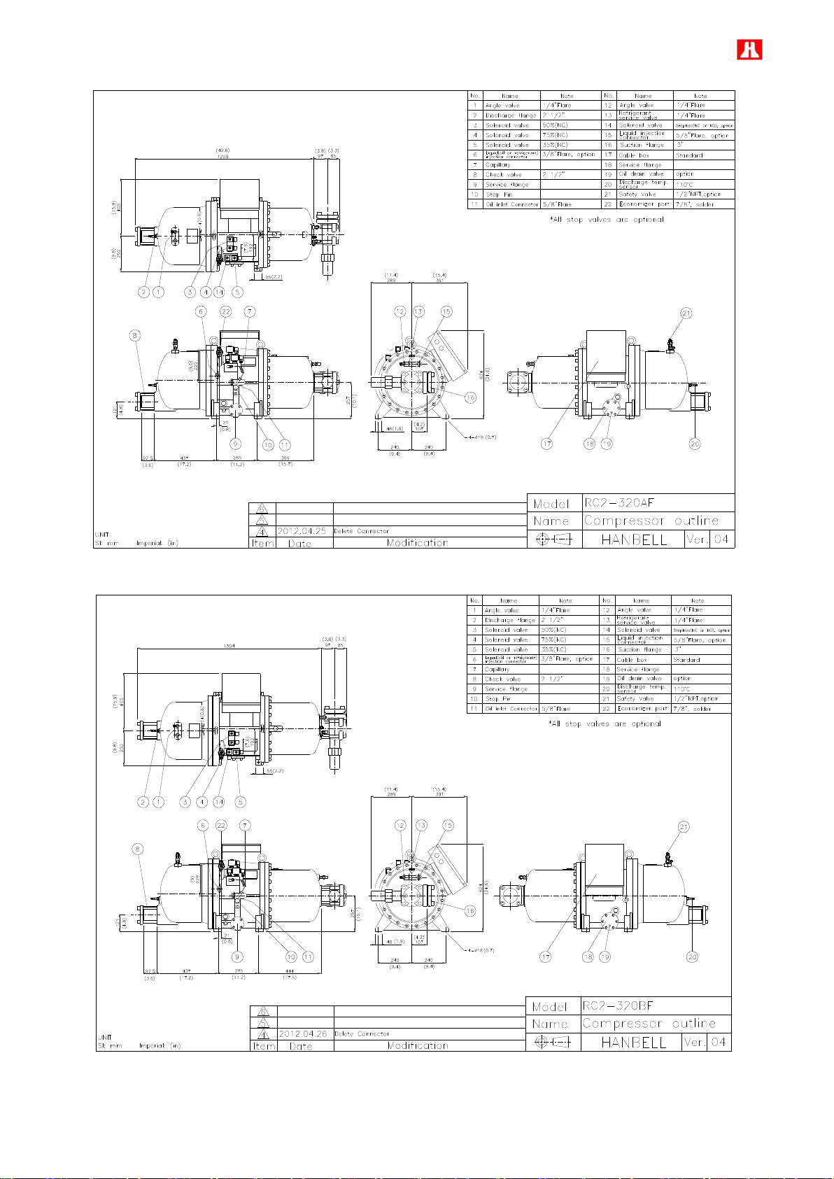
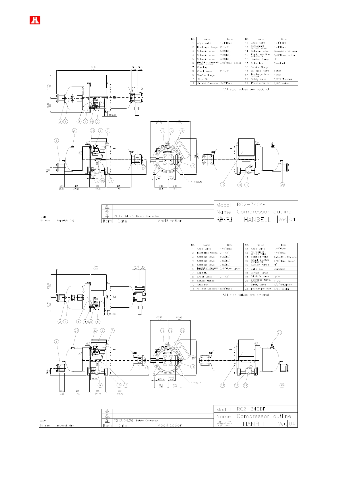
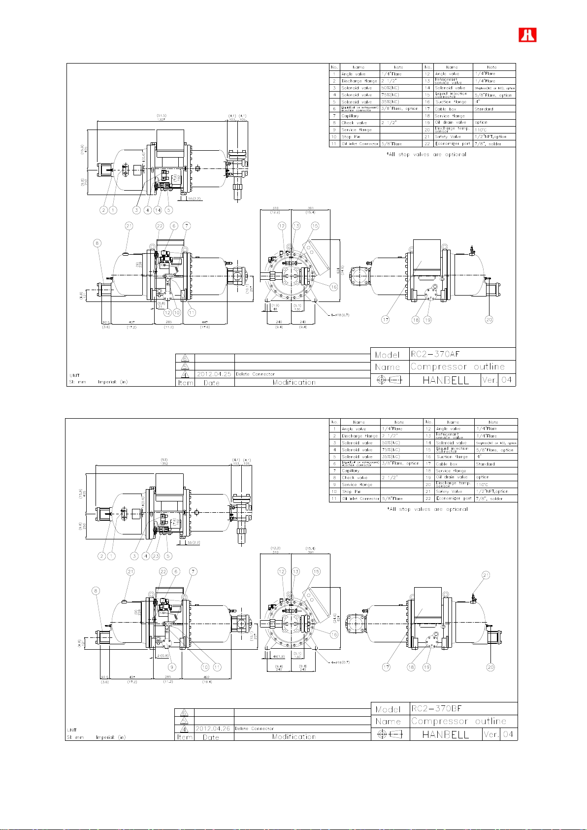
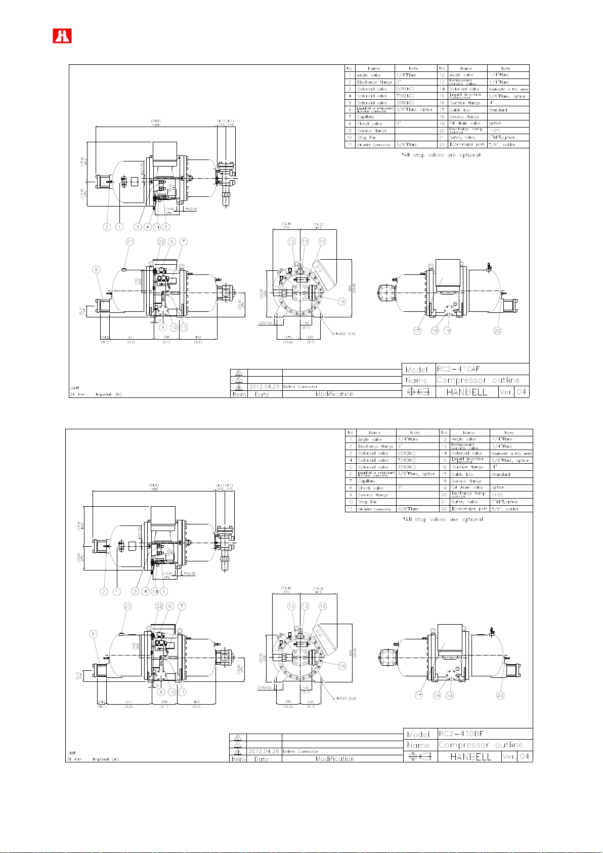
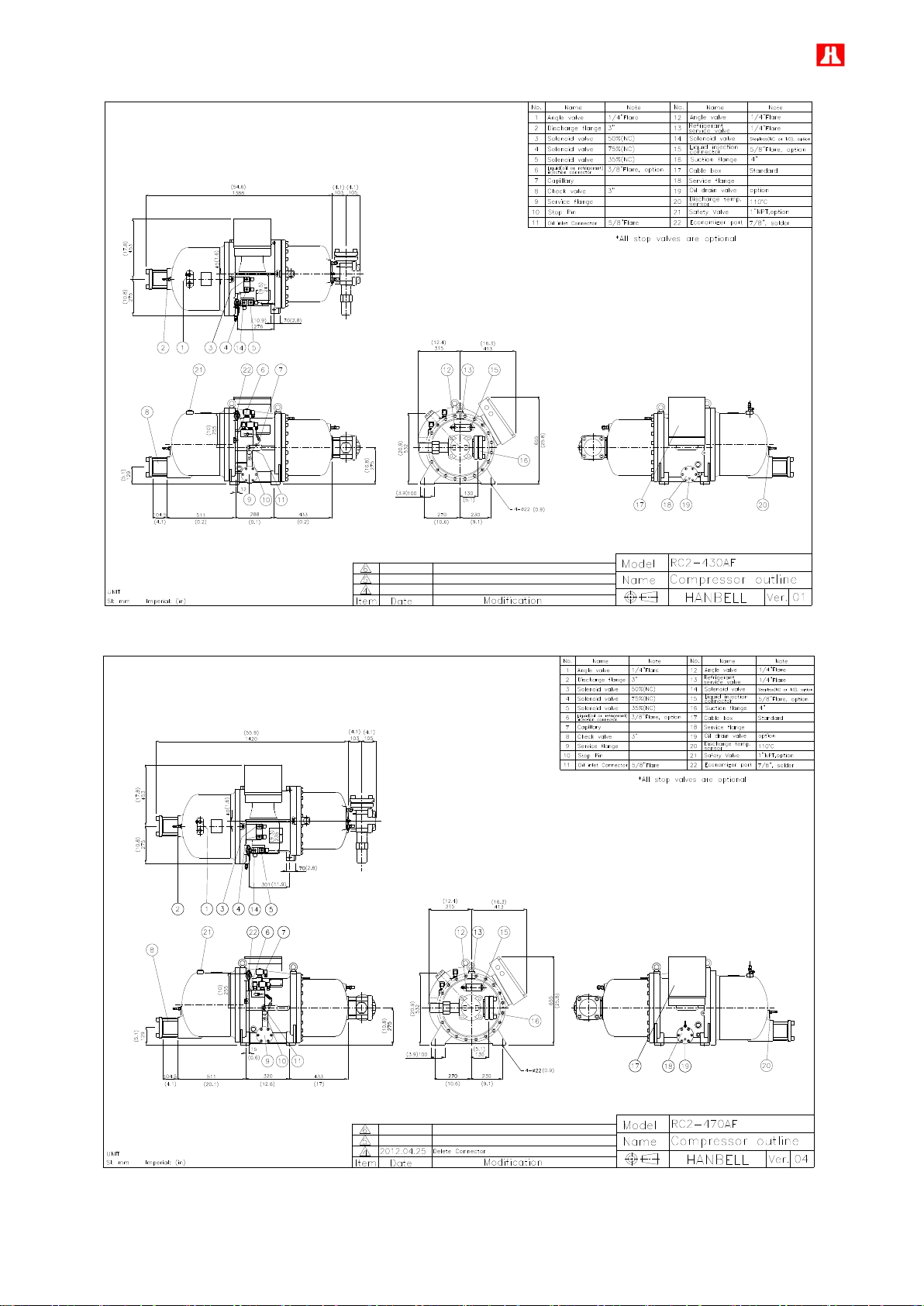
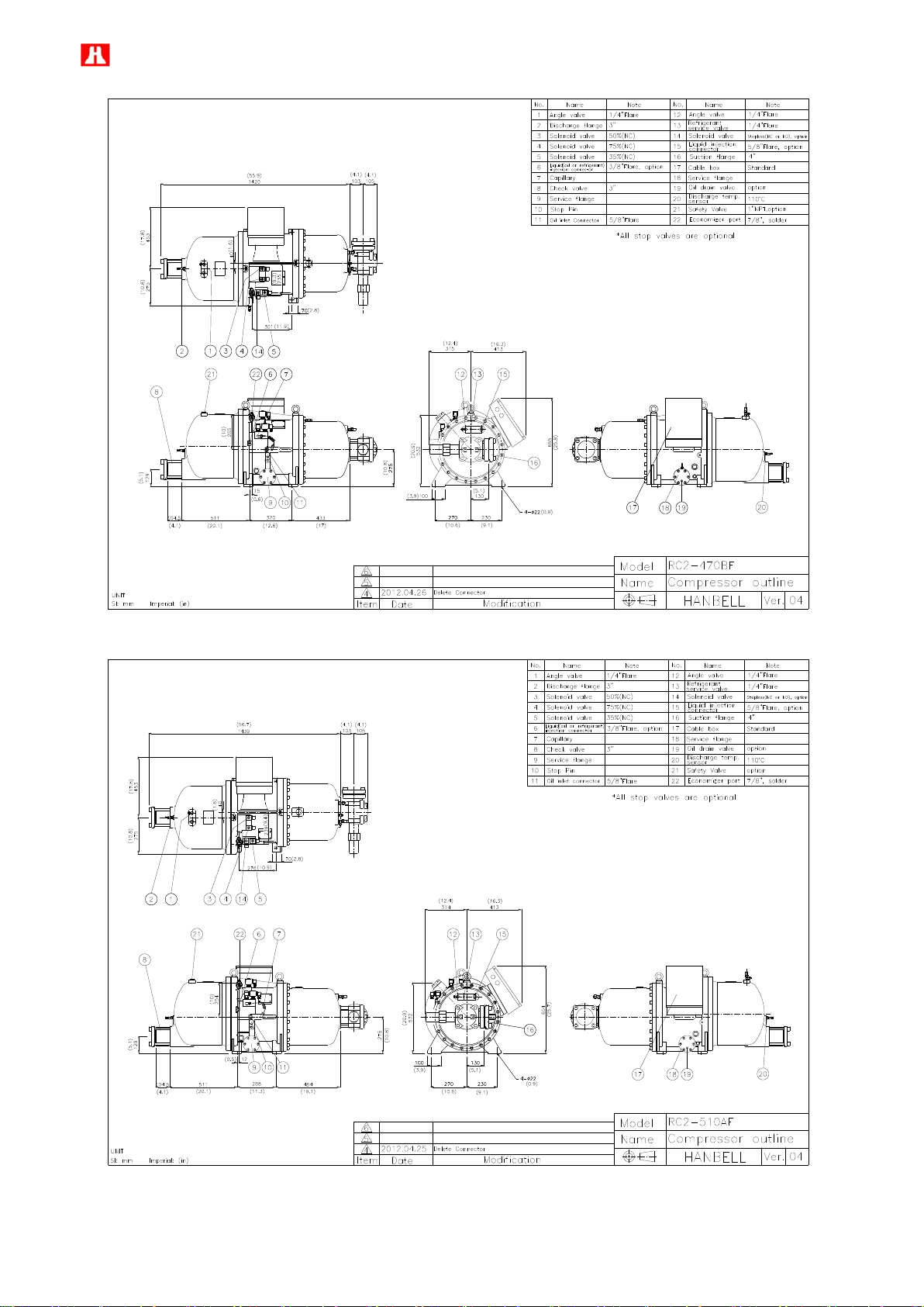
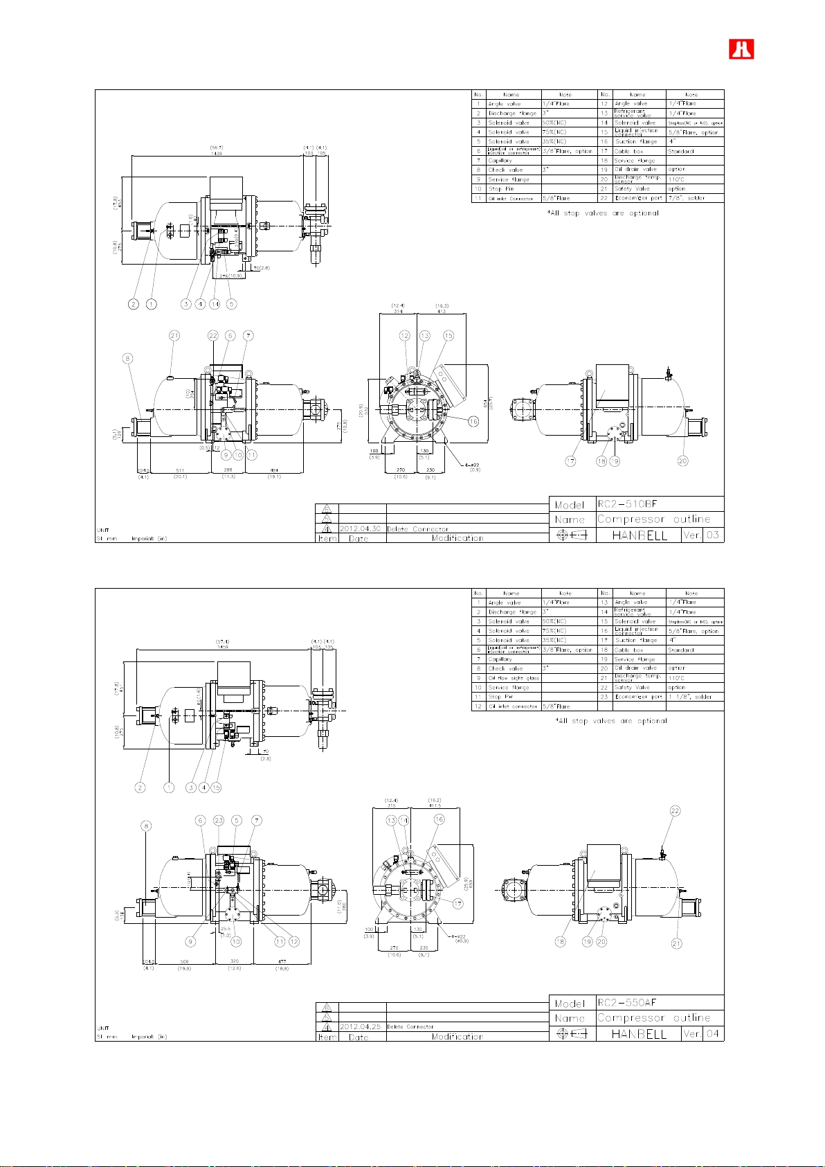
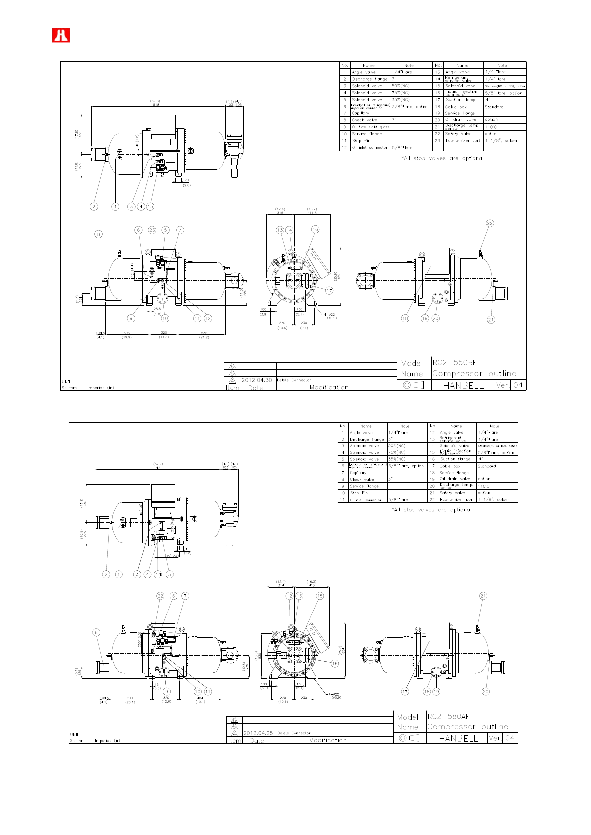
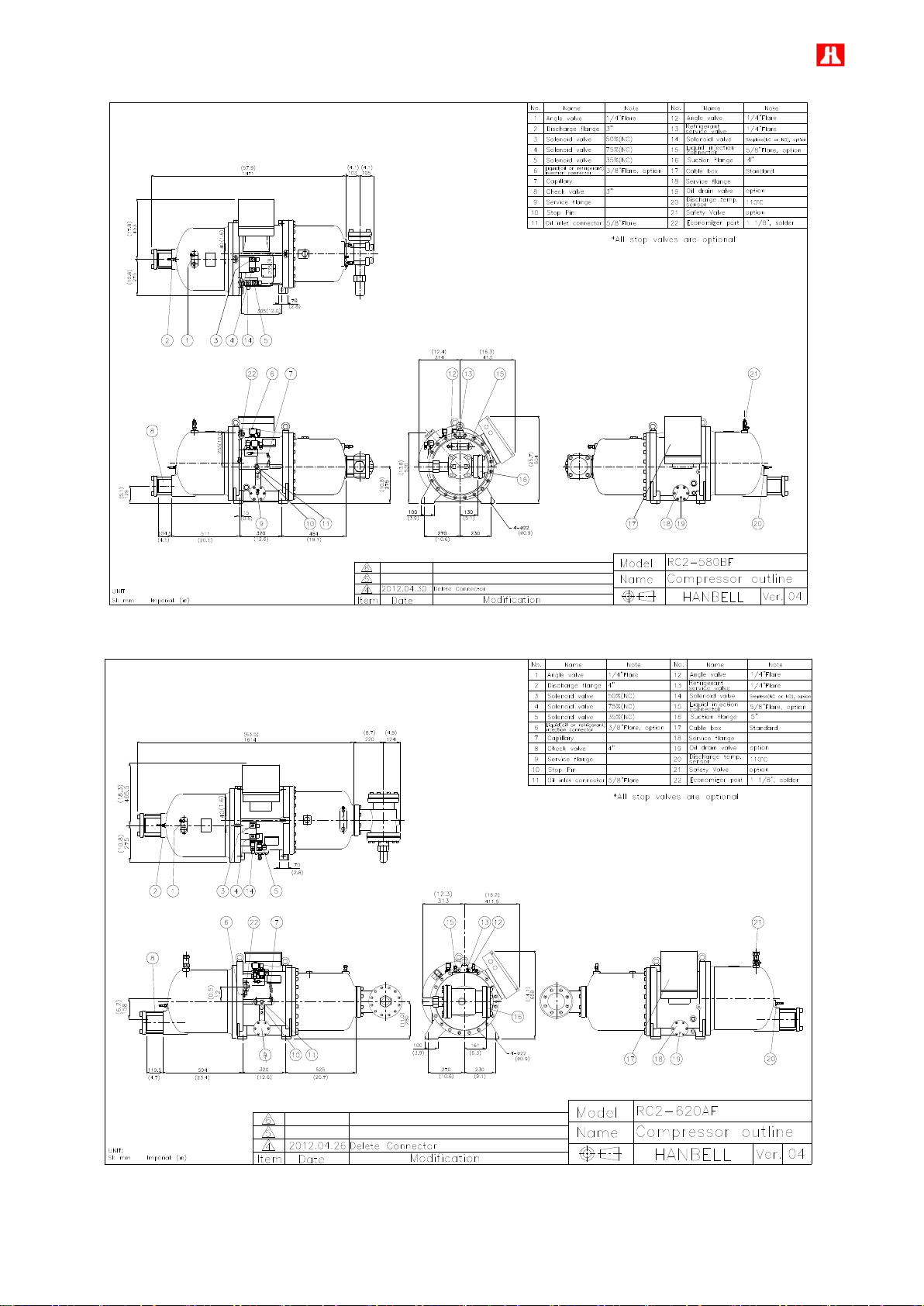
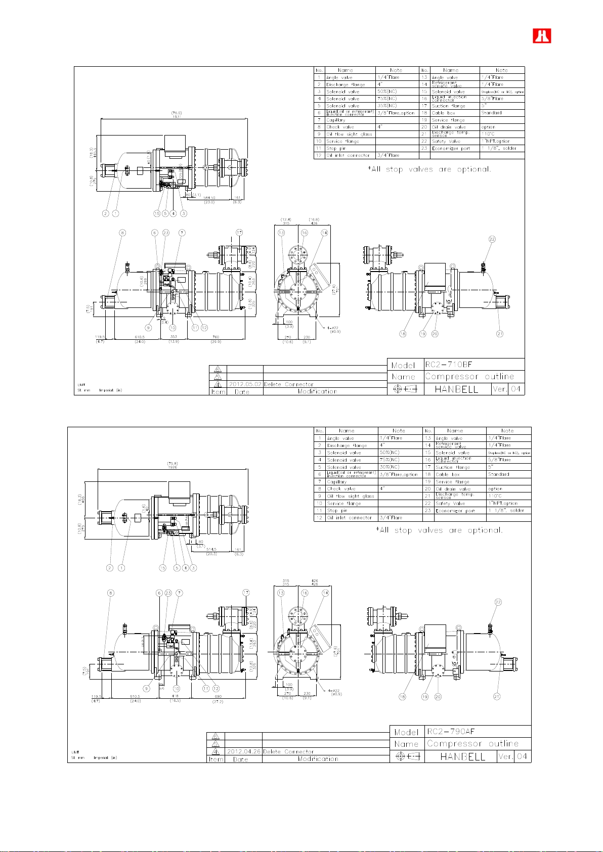
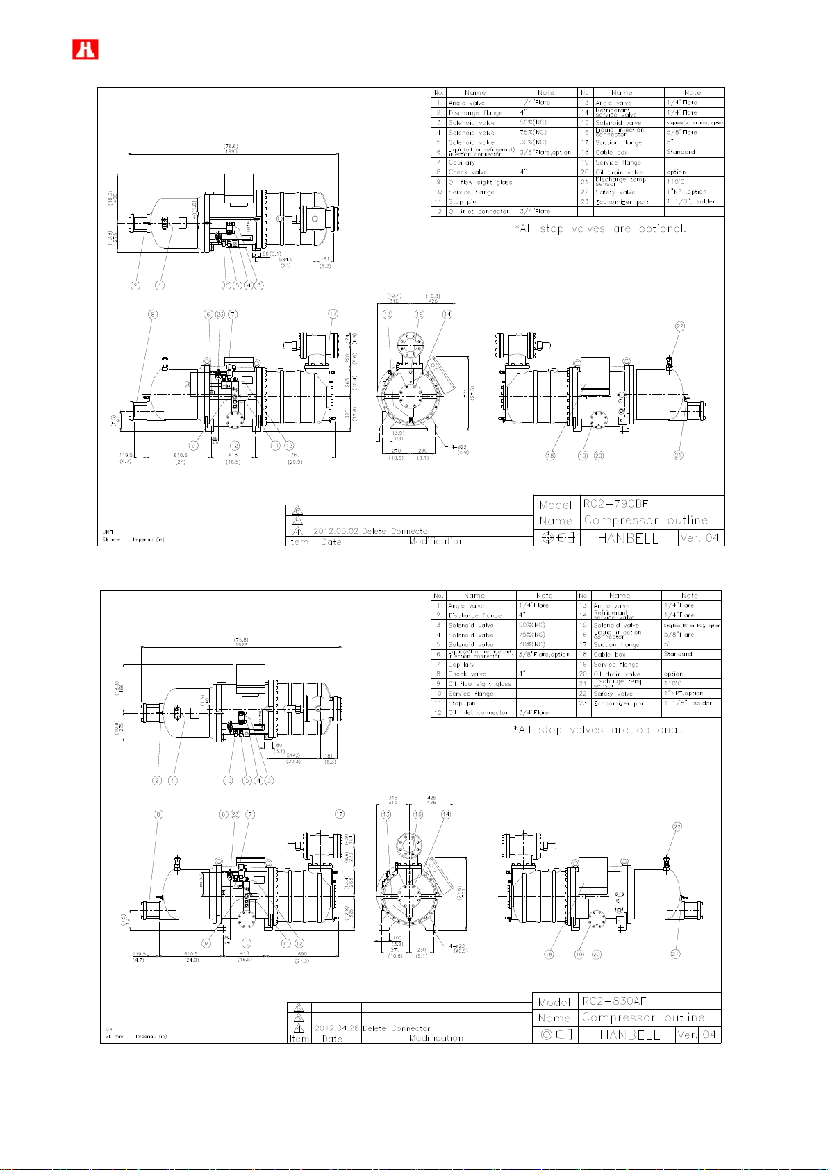
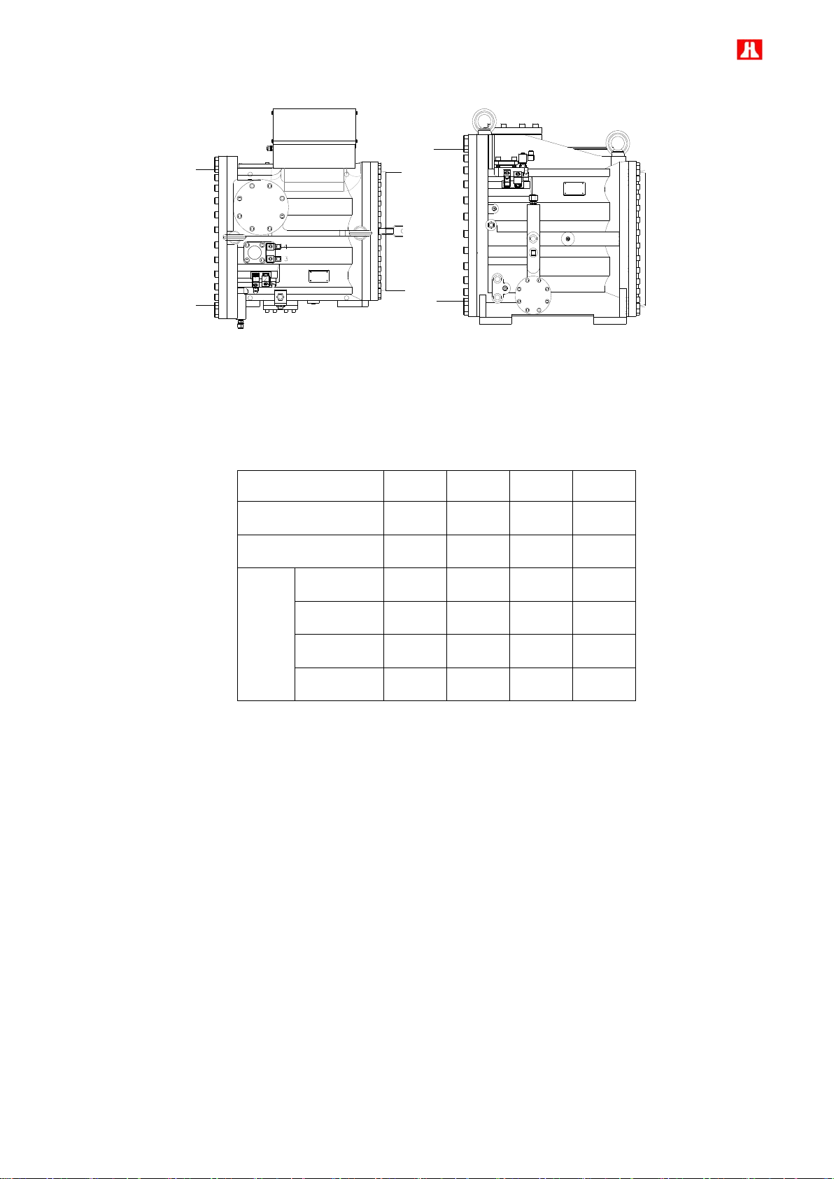
2.2 Compressor outline
Page 7
6
Page 8
7
Page 9
8
Page 10
9
Page 11
10
Page 12
11
Page 13
12
Page 14
13
Page 15
14
Page 16
15
Page 17
16
Page 18
17
Page 19
18
Page 20
19
Page 21
20
Page 22
21
Page 23

22
Page 24
23
Page 25
24
Page 26
25
Page 27
26
Page 28
27
Note: For RC2-1020BF, RC2-1130BF, RC2-1270BF and RC2-1530BF outline drawing, please refer to those of
RC2-1020AF, RC2-1130AF, RC2-1270AF, and RC2-1530AF
Page 29
28
No.
Description
No.
Description
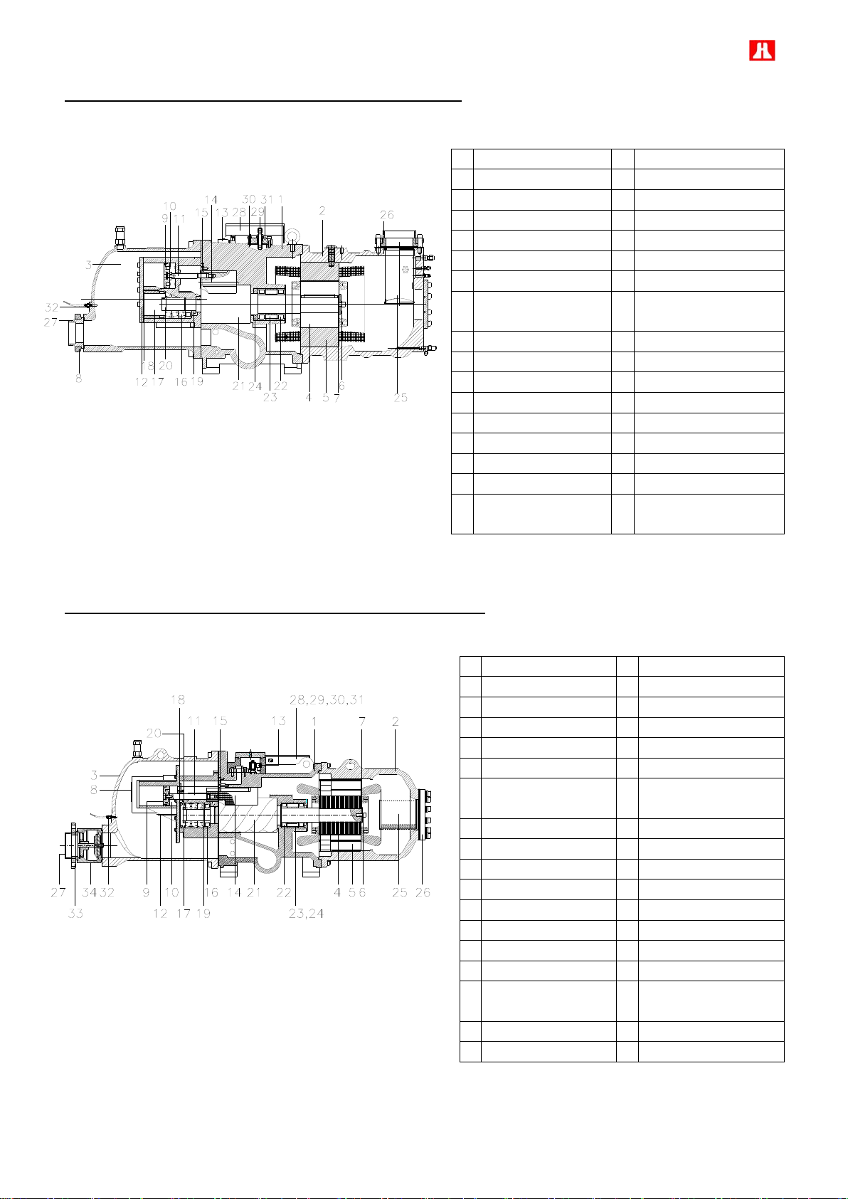
1
Compressor casing
15
Discharge bearings
2
Motor casing
16
Discharge fixed ring
3
Discharge casing
17
Disc spring
4
Motor rotor assembly
18
Bearing slot nut
5
Motor stator assembly
19
Male rotor
6
Motor rotor washer
20
Suction bearings
7
Motor rotor spacer ring
21
Suction filter
8
Discharge connect flange
22
Suction flange
9
Piston
23
Discharge flange bushing
10
Piston ring
24
Cable box
11
Piston rod
25
Power bolt
12
Bearing seat cover plate
26
Terminal cover plate
13
Modulation slide valve
27
PTC discharge temperature sensor
14
Slide valve key
No.
Description
No.
Description
1
Compressor casing
17
Disc spring
2
Motor casing
18
Bearing slot nut
3
Discharge casing
19
Male rotor
4
Motor rotor assembly
20
Suction bearings
5
Motor stator assembly
21
Suction bearings
inner/outer spacer ring
6
Motor rotor washer
22
Oil guiding ring
7
Motor rotor spacer ring
23
Suction filter
8
Piston
24
Suction flange
9
Piston ring
25
Cable box
10
Piston rod
26
Power bolt
11
Bearing seat cover plate
27
Thermostat terminals
12
Modulation solenoid
valve
28
Terminal cover plate
13
Modulation slide valve
29
Discharge connect flange
14
Slide valve key
30
Discharge flange bushing
15
Discharge bearings
31
PTC discharge
temperature sensor
16
Discharge fixed ring
2.3 Compressor construction
RC2-100, RC2-140, RC2-180 F type Construction
RC2-200, RC2-230, RC2-260, RC2-300, RC2-310, RC2-320, RC2-340, RC2-370,
RC2-410, RC2-430, RC2-470, RC2-510, RC2-550, RC2-580, RC2-620 F type Construction
Page 30
29
RC2-710, RC2-790, RC2-830, RC2-930 F type Construction
No.
Description
No.
Description
1
Compressor casing
17
Discharge fixed ring
2
Motor casing
18
Disc spring
3
Discharge casing
19
α-Balance piston
4
Motor rotor assembly
20
Bearing slot nut
5
Motor stator assembly
21
Male rotor
6
Motor rotor washer
22
Suction bearings
7
Motor rotor spacer ring
23
Suction bearings inner/outer
spacer ring
8
Discharge connect flange
24
Oil guiding ring
9
Piston
25
Suction filter
10
Piston spring
26
Suction flange
11
Piston rod
27
Discharge flange bushing
12
Bearing seat cover plate
28
Cable box
13
Modulation solenoid valve
29
Power bolt
14
Modulation slide valve
30
Thermostat terminals
15
Slide valve key
31
Motor cable cover plate
16
Discharge bearings
32
PTC discharge temperature
sensor
No.
Description
No.
Description
1
Compressor casing
18
Disc spring
2
Motor casing
19
Balance piston
3
Discharge casing
20
Bearing slot nut
4
Motor rotor assembly
21
Male rotor
5
Motor stator assembly
22
Suction bearings
6
Motor rotor washer
23
Suction bearings inner/outer
spacer ring
7
Motor rotor spacer ring
24
Oil guiding ring
8
Muffler
25
Suction filter
9
Piston
26
Suction flange
10
Piston spring
27
Discharge flange bushing
11
Piston rod
28
Cable box
12
Bearing seat cover plate
29
Power bolt
13
Modulation solenoid valve
30
Thermostat terminals
14
Modulation slide valve
31
Motor cable cover plate
15
Slide valve key
32
PTC discharge temperature
sensor
16
Discharge bearings
33
Discharge connect flange
17
Discharge fixed ring
34
Check valve
RC2-1020, RC2-1130, RC2-1270, RC2-1530 F type Construction
Page 31

30
1
2
4
3
2.4 Capacity control system
The RC2-F series screw compressors are equipped with either 3-steps/4-steps or continuous (step-less) capacity
control system. Both capacity control systems consist of a modulation slide valve, piston rod, cylinder, piston and
piston rings. The slide valve and the piston are connected by a piston rod. The principle of operation is using the oil
pressure to drive the piston in the cylinder. The lubrication oil flows from the external oil separator through the oil
filter to the main oil inlet port and then fills into the cylinder due to the positive oil pressure force which is bigger
than the spring force plus the force from high pressure gas. The positive pressure differential causes the piston to
move toward the loading direction in the cylinder. When the slide valve moves toward the loading direction, the
effective suction volume increased in the compression chamber. This means the displacement of refrigerant gas
also increases, as a result the refrigeration capacity also increases. However, when any of the step solenoid valve
(for 4-step capacity control system) is opened, the high pressure oil in the cylinder bypasses to the suction side,
which causes the piston and the slide valve move toward the unloading direction, and then some of the refrigerant
gas bypasses from the compression chamber back to the suction end. As a result, the refrigeration capacity
decreases because of the reduction of displacement of refrigerant gas flowing in the system.
The piston spring is used to push the piston back to its original position, i.e. minimum load position in order to
reduce the starting current for the next starting-up. If the compressor started at full load capacity it may result in
over current start. The modulation solenoid valves are controlled by a micro controller or temperature switch to
modulate the piston position smoothly with stable output of capacity.
If the oil filter cartridge or modulation solenoid valves are not working well in the capacity control system, this may
result in the abnormality and ineffectiveness of the capacity control system. Before stopping the compressor,
HANBELL strongly recommends that the unloading solenoid valve of step-less control system or minimum load
solenoid valve of 3/4 steps control system should be kept opened for 30~60 seconds so that oil pressure in the
cylinder can be released. When starting the compressor next time, the slide is at its minimum load position for a
light duty start.
The capacity control solenoid valves of different models are equipped as the pictures shown below. Please refer
to the pictures and description for the detail of capacity control logic.
RC2-100F/140F/180F RC2-200F~RC2-930F
Page 32
31
Top view Side view
Solenoid Valve
1 2 3
4
Normal Open / Normal Close
--
NC
NC
NC
Standard / Optional
--
STANDARD
STANDARD
STANDARD
Control
Logic
S %
(Start)
--
ON
OFF
OFF
M1 %
(66% or 50%)
--
OFF
ON
OFF
M2 %
(75%)
--
OFF
OFF
ON
F %
(Full Load / 100%)
--
OFF
OFF
OFF
RC2-1020F ~ RC2-1530F
3 or 4 steps capacity control
Note:
ON : Solenoid valve energized
OFF: Solenoid valve not energized
Warning:If the S % ( start ) capacity is essential to be kept running for a long time, the problem of oil return,
motor cooling and high discharge temperature and other problem should be considered seriously to prevent
inappropriate operation of the compressor which may damage it.
Page 33

32
Solenoid Valve
1 1 2 3 4
Normal Open / Normal Close
NO
NC
NC
--
--
Standard / Optional
OPTIONAL
STANDARD
STANDARD
--
--
Control
Logic
Start
ON
OFF
ON
--
--
Loading
OFF
ON
OFF
--
--
Unloading
ON
OFF
ON
--
--
Hold /
Stable
ON
OFF
OFF
--
--
Stepless capacity control
Note:
ON : Solenoid valve energized
OFF: Solenoid valve not energized
In continuous capacity control system, two normally close solenoid valve are equipped as standard. These two
solenoid valves are controlled by the chiller temperature controller, hence refrigeration capacity can be modulated
between S (start) %100% continuously. The exactness of temperature control depends on the precision of
temperature sensor.
The timer resolution of control system, affects the capacity control’s speed. Hanbell recommends setting the timer
resolution between 0.1~1second to have a precise capacity control. If the resolution is set more than 1 second,
then it is recommended to add a flow control device to obtain a smooth capacity control.
Page 34

33
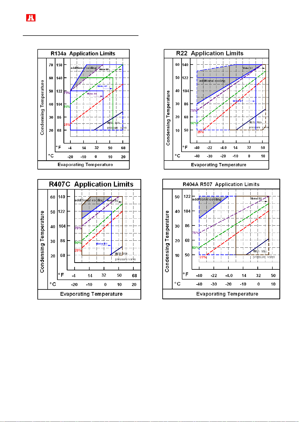
2.5 Compressor application limits
Compressor Operating Limits vary significantly with the type of refrigerant used. The operating limits shown below
are based on saturated suction and discharge operating conditions. For continuous operation over extended
periods of time, it is important to operate the compressor within these limits to maintain proper compressor life.
Operating at extra low saturated suction temperature, may cause oil management problem, and operating at extra
high saturated condensing temperature may shorten the compressor life due to insufficient compressor chamber
cooling or oil supply for lubrication.
a. Application limits of RC2-100F~RC2-930F are described on the respective refrigerant charts.
Page 35
34
b. Application limits of of RC2-1020F~RC2-1530F are described on the respective refrigerant charts.
Note :
1. When Hanbell screw compressor operates in partial or full load within limits, temperature of motor coil and
discharge will rise concurrently. In order to keep compressor running safely, Hanbell recommends using the
following additional cooling methods :
(1) Oil cooler. (2) Liquid injection to chamber. (3) Liquid injection to motor.
Please refer to Hanbell selection software for calculation and chapter 9—application for design reference.
2. The minimum discharge superheat is recommended to be kept 10°k higher than the condensing temperature
( normally discharge superheat is around 20°K for R-134a,R404A, R507A and 30°K for R22, R407C) to avoid
liquid filling back to compressor and lubrication failure. According to EN12900, the minimum suction
superheat is 10°k and liquid sub-cooling is 0°k.
Page 36

35
V
Pd
Pd'
V
Pd<Pd'
P
Pd, Pd'
V
Pd=Pd'
P
Pd>Pd'
Pd'
Pd
P
3. Hanbell recommends monitoring oil pressure differential by pressure differential switch passively or by
Gcmkg2/
Gcmkg2/
Under compression (CR > Pi)
Over compression (CR < Pi)
CR = Pi
Loss of work
Loss of work
1
2
3
4
Ps
1
2
3
4
Ps
Ps
2
3
4
1
additional oil pump actively and keep it 4
over the suction pressure for adequate seal, lubrication
and capacity control. This is very important especially when the condensing temperature is low and the
evaporating temperature is high like the application in water-cooled flooded chillers and normally its high-low
pressure differential tends to be less than 4
. In this kind of situation, installation of oil pump is
recommended to ensure sufficient oil supply.
4. All models’ motor cooling are by refrigerant returned from evaporator. If compressors run continuously at
partial load below 50%, failure of motor coils might happen due to insufficient motor cooling. Therefore,
Hanbell emphasizes installation of liquid injection system to motor to make sure adequate cooling at motor
coils for safe running of compressors.
5. Contact with Hanbell to verify potential operating conditions outside the limits shown.
2.6 Compressor design feature
2.6.1 Compressor volume ratio
The Volume ratio (Vi) of the compressor can be defined as the ratio of suction volume of gas divided by discharge
volume of gas of the compressor. The volume ratio directly affects the internal compression ratio or Pi of the
compressor. A low Vi compressor corresponds to a low compression ratio compressor and high Vi compressors
are used on higher compression ratio systems. In the equation below, in order to avoid over or under compression,
the system compression ratio (CR) should be equal to the compressor internal compression ratio (Pi). If CR is not
equal to Pi, it would cause extra compensation of work / power of compressor and also decrease C.O.P. Refer
also to the P-V (pressure – volume) diagram below to show the relation.
CR =
Pd/Ps
Pi = Vi
k
Vi = Vs/Vd
Where: CR: system compression ratio Pi: internal compression ratio
Vi: internal volume ratio Pd: system pressure (absolute pressure)
Pd’: discharge pressure (absolute pressure) Ps: suction pressure (absolute pressure)
Vs: suction volume Vd: discharge volume K: refrigerant specific heat ratio
Page 37

36
B - B' View
A - A' View
P2
P1
P2
A'
B
A
P1
PART LOAD
FULL LOAD
Vi 2.6
Vi 3.5
Note:
1. Hanbell recommends using selection program to get the suggested Vi because inappropriate Vi selection will
cause higher power consumption, vibration and discharge temperature.
2. When compressor running below 70% capacity, because the slide is partially inside the compression chamber
and results the inappropriate Vi, the system will suffer higher discharge temperature. Therefore Hanbell
recommends not running compressor under partial load in a long time.
To ensure compressor performs in a high efficiency condition and prevent from additional power loss, built-in Vi is
designed for all models ( Vi = 2.2, 2.6, 3.0, 3.5, 4.8 ), so the customer could select the suitable Vi according to
different working condition. Please refer to Hanbell selection software to get the recommended Vi for different
working condition.
Built-in fixed type Vi
2.6.2 Floating type medium pressure ( for application with economizer)
Normally, a fix type medium pressure compressor when combine with economizer, the economizer can only
develop their effect in full load condition or closed to full load condition.
RC2-F series uses floating medium pressure design, the floating mechanical design is shown in the next drawing.
Economizer can be functioned not only in full load condition, but also in partial load condition. The economizer can
reach the best medium pressure value and develops the maximum efficiency.
Floating type medium pressure explanation
Medium pressure’s position will vary as shown in the above drawing. When the slide is at full load position, the
medium pressure is P1. When the slide is at partial load position, the medium pressure is P2.
Page 38

37
2.7 MCC and LRA
Model
50Hz
60Hz Unit: Ampere
380V
400V
415V
208V
220V
230V
380V
440V
460V
480V
575V
MCC
LRA
MCC
LRA
MCC
LRA
MCC
LRA
MCC
LRA
MCC
LRA
MCC
LRA
MCC
LRA
MCC
LRA
MCC
LRA
MCC
LRA
(Y/△)
(Y/△)
(Y/△)
(Y/△)
(Y/△)
(Y/△)
(Y/△)
(Y/△)
(Y/△)
(Y/△)
(Y/△)
RC2-100AF
53
58/175
50
60/ 180
49
55/165
115
127/380
109
117/350
104
120/360
63
70/210
55
58/175
52
60/180
50
55/165
42
48/145
RC2-140AF
73
77/230
70
80/240
67
73/220
160
175/525
151
153/460
145
160/480
88
97/290
76
77/230
72
80/240
69
73/220
58
63/190
RC2-180AF
97
103/310
92
108/325
89
98/295
213
230/690
202
198/595
193
207/620
117
125/375
101
103/310
96
108/325
92
98/295
77
85/255
RC2-200AF
103
103/310
98
108/325
94
98/295
226
230/690
214
198/595
204
207/620
124
125/375
107
103/310
102
108/325
98
98/295
82
85/255
RC2-230AF
124
160/480
117
167/500
113
155/465
270
360/1080
256
302/905
244
315/945
148
200/600
128
160/480
122
167/500
117
155/465
98
125/375
RC2-260AF
138
160/480
131
167/500
126
155/465
302
360/1080
286
302/905
273
315/945
165
200/600
143
160/480
137
167/500
131
155/465
109
125/375
RC2-300AF
155
200/600
147
208/625
142
180/540
340
462/1385
322
375/1125
308
392/1175
186
245/735
161
200/600
154
208/625
147
180/540
123
157/470
RC2-310AF
163
200/600
155
208/625
149
180/540
360
462/1385
341
375/1125
326
392/1175
197
245/735
170
200/600
163
208/625
156
180/540
130
157/470
RC2-320AF
167
200/600
158
208/625
153
180/540
366
462/1385
346
375/1125
331
392/1175
200
245/735
173
200/600
165
208/625
158
180/540
132
157/470
RC2-340AF
178
230/690
169
240/720
163
218/655
388
503/1510
367
460/1380
351
480/1440
213
270/810
184
230/690
176
240/720
168
218/655
140
182/545
RC2-370AF
194
230/690
185
240/720
178
218/655
426
503/1510
403
460/1380
386
480/1440
233
270/810
202
230/690
193
240/720
185
218/655
154
182/545
RC2-410AF
216
233/700
205
243/730
198
230/690
- - - - -
-
260
273/820
224
233/700
215
243/730
206
230/690
172
183/550
RC2-430AF
230
233/700
218
243/730
211
230/690
- - - - -
-
277
273/820
239
233/700
229
243/730
219
230/690
183
183/550
RC2-470AF
248
270/810
236
282/845
227
265/795
- - - - -
-
300
328/985
259
270/810
248
282/845
238
265/795
198
220/660
RC2-510AF
271
270/810
258
282/845
248
265/795
- - - - -
-
327
328/985
282
270/810
270
282/845
259
265/795
216
220/660
RC2-550AF
292
292/875
277
305/915
267
283/850
- - - - -
-
350
372/1115
302
292/875
289
305/915
277
283/850
231
250/750
RC2-580AF
304
292/875
288
305/915
278
283/850
- - - - -
-
365
372/1115
316
292/875
302
305/915
289
283/850
242
250/750
RC2-620AF
317
407/1220
301
428/1285
290
387/1160
- - - - -
-
381
482/1445
329
407/1220
315
428/1285
301
387/1160
252
323/970
RC2-710AF
365
447/1340
347
467/1400
334
432/1295
- - - - -
-
439
583/1750
379
447/1340
363
467/1400
348
432/1295
290
373/1120
RC2-790AF
404
477/1430
384
498/1495
370
457/1370
- - - - -
-
486
643/1930
420
477/1430
402
498/1495
385
457/1370
321
388/1165
RC2-830AF
422
522/1565
401
545/1635
387
495/1485
- - - - -
-
507
728/2185
438
522/1565
419
545/1635
402
495/1485
335
462/1385
RC2-930AF
490
663/1990
465
693/2080
448
617/1850
- - - - -
-
589
823/2470
509
663/1990
487
693/2080
466
617/1850
389
555/1665
RC2-1020AF(A1)
360
583/1750
342
613/1840
330
537/1610
434
763/2290
374
583/1750
358
613/1840
343
537/1610
287
493/1480
RC2-1020AF(A2)
536
753/2260
510
793/2380
491
690/2070
645
945/2835
557
753/2260
533
793/2380
510
690/2070
426
635/1905
RC2-1130AF(A1)
395
583/1750
375
613/1840
362
537/1610
475
763/2290
410
583/1750
393
613/1840
376
537/1610
314
493/1480
RC2-1130AF(A2)
588
753/2260
559
793/2380
538
690/2070
709
945/2835
612
753/2260
585
793/2380
561
690/2070
468
635/1905
RC2-1270AF(A1)
457
753/2260
434
793/2380
419
690/2070
550
943/2830
475
753/2260
455
793/2380
436
690/2070
364
635/1905
RC2-1270AF(A2)
682
888/2665
648
935/2805
624
782/2345
820
1168/3505
708
888/2665
677
935/2805
649
782/2345
542
717/2150
RC2-1530AF(A1)
517
753/2260
491
793/2380
474
690/2070
623
943/2830
538
753/2260
514
793/2380
493
690/2070
411
635/1905
RC2-1530AF(A2)
770
888/2665
732
935/2805
705
782/2345
927
1168/3505
800
888/2665
766
935/2805
734
782/2345
613
717/2150
Refrigerant : R134a (Y-△)
Page 39

38
Model
50Hz
60Hz Unit: Ampere
380V
400V
415V
208V
220V
230V
380V
440V
460V
480V
575V
MCC
LRA
MCC
LRA
MCC
LRA
MCC
LRA
MCC
LRA
MCC
LRA
MCC
LRA
MCC
LRA
MCC
LRA
MCC
LRA
MCC
LRA
(Y/△)
(Y/△)
(Y/△)
(Y/△)
(Y/△)
(Y/△)
(Y/△)
(Y/△)
(Y/△)
(Y/△)
(Y/△)
RC2-100BF
69
77/230
65
80/240
63
73/220
151
175/525
142
153/460
136
160/480
82
97/290
71
77/230
68
80/240
65
73/220
54
63/190
RC2-140BF
91
103/310
87
108/325
84
98/295
199
230/690
188
198/595
180
207/620
109
125/375
94
103/310
90
108/325
86
98/295
72
85/255
RC2-180BF
121
155/465
115
162/485
110
148/445
263
362/1085
249
310/930
238
323/970
144
192/575
124
155/465
119
162/485
114
148/445
95
127/380
RC2-200BF
128
155/465
122
162/485
117
148/445
282
362/1085
266
310/930
255
323/970
154
192/575
133
155/465
127
162/485
122
148/445
102
127/380
RC2-230BF
153
230/690
146
240/720
140
218/655
336
503/1510
318
460/1380
304
480/1440
184
270/810
159
230/690
152
240/720
146
218/655
122
182/545
RC2-260BF
171
230/690
163
240/720
157
218/655
376
503/1510
355
460/1380
340
480/1440
206
270/810
178
230/690
170
240/720
163
218/655
136
182/545
RC2-300BF
193
260/780
183
272/815
177
263/790
424
653/1960
401
520/1560
384
543/1630
232
343/1030
200
260/780
192
272/815
184
263/790
153
223/670
RC2-310BF
203
260/780
193
272/815
186
263/790
446
653/1960
421
520/1560
403
543/1630
244
343/1030
211
260/780
201
272/815
193
263/790
161
223/670
RC2-320BF
207
260/780
196
272/815
189
263/790
456
653/1960
431
520/1560
413
543/1630
250
343/1030
216
260/780
206
272/815
198
263/790
165
223/670
RC2-340BF
220
345/1035
209
360/1080
201
313/940
483
720/2160
457
662/1985
437
692/2075
264
407/1220
228
345/1035
218
360/1080
209
313/940
175
272/815
RC2-370BF
241
345/1035
229
360/1080
221
313/940
529
720/2160
500
662/1985
478
692/2075
289
407/1220
250
345/1035
239
360/1080
229
313/940
191
272/815
RC2-410BF
268
292/875
254
305/915
245
283/850
- - - - -
-
323
372/1115
279
292/875
267
305/915
256
283/850
214
250/750
RC2-470BF
310
407/1220
294
428/1285
284
387/1160
- - - - -
-
372
482/1445
321
407/1220
307
428/1285
294
387/1160
246
323/970
RC2-510BF
336
443/1330
319
463/1390
308
417/1250
- - - - -
-
406
535/1605
350
443/1330
335
463/1390
321
417/1250
268
382/1145
RC2-550BF
336
443/1330
319
463/1390
308
417/1250
- - - - -
-
406
535/1605
350
443/1330
335
463/1390
321
417/1250
268
382/1145
RC2-580BF
377
443/1330
358
463/1390
345
417/1250
- - - - -
-
454
535/1605
392
443/1330
375
463/1390
359
417/1250
300
382/1145
RC2-620BF
393
503/1510
374
527/1580
360
468/1405
- - - - -
-
473
627/1880
409
503/1510
391
527/1580
375
468/1405
313
422/1265
RC2-710BF
453
663/1990
430
693/2080
415
617/1850
- - - - -
-
545
823/2470
471
663/1990
450
693/2080
432
617/1850
360
555/1665
RC2-790BF
498
743/2230
473
777/2330
456
682/2045
- - - - -
-
598
958/2875
516
743/2230
494
777/2330
473
682/2045
395
600/800
RC2-830BF
534
785/2355
508
827/2480
489
863/2590
- - - - -
-
643
1067/3200
555
785/2355
531
827/2480
509
863/2590
425
658/1975
RC2-930BF
620
875/2625
589
915/2745
567
955/2865
- - - - -
-
746
1247/3740
644
875/2625
616
915/2745
591
955/2865
493
765/2295
RC2-1020BF(B1)
611
888/2665
580
935/2805
559
782/2345
735
1168/3505
635
888/2665
607
935/2805
582
782/2345
486
717/2150
RC2-1020BF(B2)
684
1085/3255
650
1142/3425
626
920/2760
823
1290/3870
710
1085/3255
680
1142/3425
651
920/2760
544
868/2605
RC2-1130BF(B1)
671
888/2665
637
935/2805
614
782/2345
806
1168/3505
697
888/2665
666
935/2805
638
782/2345
533
717/2150
RC2-1130BF(B2)
766
1085/3255
728
1142/3425
702
920/2760
922
1290/3870
796
1085/3255
762
1142/3425
730
920/2760
609
868/2605
RC2-1270BF(B1)
777
1085/3255
738
1142/3425
711
920/2760
934
1290/3870
807
1085/3255
772
1142/3425
740
920/2760
617
868/2605
RC2-1270BF(B2)
864
1338/4015
820
1160/3480
791
1213/3640
1038
1573/4720
896
1338/4015
857
1160/3480
821
1213/3640
686
1292/3875
RC2-1530BF(B1)
878
1085/3255
834
1142/3425
804
920/2760
1056
1290/3870
912
1085/3255
873
1142/3425
836
920/2760
698
868/2605
RC2-1530BF(B2)
996
1393/4180
946
1195/3585
912
1263/3790
1199
1633/4900
1035
1393/4180
990
1195/3585
949
1263/3790
792
957/2870
Refrigerant : R22, R407C, R404A (Y-△)
Page 40

39
Refrigerant : R134a (PWS)
Model
50Hz
60Hz Unit: Ampere
380V
400V
415V
208V
220V
230V
380V
440V
460V
480V
575V
MCC
LRA
MCC
LRA
MCC
LRA
MCC
LRA
MCC
LRA
MCC
LRA
MCC
LRA
MCC
LRA
MCC
LRA
MCC
LRA
MCC
LRA
(△/△△)
(△/△△)
(△/△△)
(△/△△)
(△/△△)
(△/△△)
(△/△△)
(△/△△)
(△/△△)
(△/△△)
(△/△△)
RC2-100AF
53
79/165
50
84/175
49
74/155
115
170/355
109
156/325
104
166/345
63
86/190
55
79//165
52
84/175
50
74/155
42
62/130
RC2-140AF
73
108/225
70
113/235
67
101/210
160
238/495
151
211/440
145
221/460
88
125/160
76
108/225
72
110/230
69
101/210
58
79/165
RC2-180AF
97
155/310
92
163/325
89
145/290
213
338/675
202
305/610
193
320/640
117
185/370
101
155/310
96
163/325
92
145/290
77
118/235
RC2-200AF
103
155/310
98
163/325
94
145/290
226
338/675
214
305/610
204
320/640
124
185/370
107
155/310
102
163/325
98
148/295
82
118/235
RC2-230AF
124
303/505
117
285/475
113
267/445
270
645/1075
256
618/1030
244
573/955
148
360/600
128
303/505
122
285/475
117
267/445
98
237/395
RC2-260AF
138
303/505
131
285/475
126
267/445
302
645/1075
286
618/1030
273
573/955
165
360/600
143
303/505
137
285/475
131
267/445
109
237/395
RC2-300AF
155
350/565
147
329/530
142
322/520
340
822/1325
322
763/1230
308
704/1135
186
428/690
161
350/565
154
329/530
147
322/520
123
273/440
RC2-310AF
163
350/565
155
329/530
149
322/520
360
822/1325
341
763/1230
326
704/1135
197
428/690
170
350/565
163
329/530
156
322/520
130
276/445
RC2-320AF
167
350/565
158
329/530
153
322/520
366
822/1325
346
763/1230
331
704/1135
200
428/690
173
350/565
165
329/530
158
322/520
132
276/445
RC2-340AF
178
462/710
169
423/650
163
410/630
388
943/1450
367
868/1335
351
920/1415
213
546/840
184
462/710
176
423/650
168
410/630
140
358/550
RC2-370AF
194
462/710
185
423/650
178
410/630
426
943/1450
403
868/1335
386
920/1415
233
546/840
202
462/710
193
423/650
185
410/630
154
358/550
RC2-410AF
216
475/730
205
497/765
198
429/660
- - - - -
-
260
553/850
224
475/730
215
497/765
206
429/660
172
374/575
RC2-430AF
230
475/730
218
497/765
211
429/660
- - - - -
-
277
553/850
239
475/730
229
497/765
219
429/660
183
374/575
RC2-470AF
248
571/840
236
598/880
227
513/755
- - - - -
-
300
677/995
259
571/840
248
598/880
238
513/755
198
439/645
RC2-510AF
271
571/840
258
598/880
248
513/755
- - - - -
-
327
677/995
282
571/840
270
598/880
259
513/755
216
439/645
RC2-550AF
292
615/905
277
646/950
267
596/875
- - - - -
-
350
779/1145
302
615/905
289
646/950
277
595/875
231
476/700
RC2-580AF
304
615/905
288
646/950
278
595/875
- - - - -
-
365
779/1145
316
615/905
302
646/950
289
595/875
242
476/700
Page 41

40
Model
50Hz
60Hz Unit: Ampere
380V
400V
415V
208V
220V
230V
380V
440V
460V
480V
575V
MCC
LRA
MCC
LRA
MCC
LRA
MCC
LRA
MCC
LRA
MCC
LRA
MCC
LRA
MCC
LRA
MCC
LRA
MCC
LRA
MCC
LRA
(△/△△)
(△/△△)
(△/△△)
(△/△△)
(△/△△)
(△/△△)
(△/△△)
(△/△△)
(△/△△)
(△/△△)
(△/△△)
RC2-100BF
69
108/225
65
113/235
63
101/210
151
238/495
142
211/440
136
221/460
82
125/260
71
108/225
68
113/235
65
101/210
54
82/170
RC2-140BF
91
155/310
87
163/325
84
145/290
199
338/675
188
305/610
180
320/640
109
185/370
94
155/310
90
163/325
86
145/290
72
118/235
RC2-180BF
121
225/425
115
239/450
110
207/390
263
480/905
249
444/840
238
466/880
144
254/480
124
225/425
119
239/450
114
207/390
95
172/325
RC2-200BF
128
225/425
122
239/450
117
207/390
282
480/905
266
445/840
255
466/880
154
254/480
133
225/425
127
239/450
122
207/390
102
172/325
RC2-230BF
153
350/565
146
329/530
140
322/520
336
822/1325
318
763/1230
304
704/1135
184
428/690
159
350/565
152
329/530
146
322/520
122
273/440
RC2-260BF
171
462/710
163
423/650
157
410/630
376
943/1450
355
868/1335
340
920/1415
206
546/840
178
462/710
170
423/650
163
410/630
136
358/550
RC2-300BF
193
507/780
183
497/765
177
481/740
424
1260/1940
401
1121/1725
384
1004/1545
232
614/945
200
507/780
192
497/765
184
481/740
153
403/620
RC2-310BF
203
507/780
193
497/765
186
481/740
446
1261/1940
421
1121/1725
403
1004/1545
244
614/945
211
507/780
201
497/765
193
481/740
161
403/620
RC2-320BF
207
507/780
196
497/765
189
481/740
456
1261/1940
431
1121/1725
413
1004/1545
250
614/945
216
507/780
206
497/765
198
481/740
165
403/620
RC2-340BF
220
663/1020
209
640/985
201
608/935
483
1628/2505
457
1342/2065
437
1495/2300
264
777/1195
228
663/1020
218
640/985
209
608/935
175
527/810
RC2-370BF
241
663/1020
229
640/985
221
608/935
529
1628/2505
500
1342/2065
478
1495/2300
289
777/1195
250
663/1020
239
640/985
229
608/935
191
527/810
RC2-410BF
268
615/905
254
646/950
245
595/875
- - - - -
-
323
779/1145
279
615/905
267
646/950
256
595/875
214
476/700
RC2-470BF
310
870/1280
294
915/1345
284
826/1215
- - - - -
-
372
1030/1515
321
870/1280
307
915/1345
294
826/1215
246
690/1015
RC2-510BF
336
952/1400
319
996/1465
308
891/1310
- - - - -
-
406
1142/1680
350
952/1400
335
996/1465
321
891/1310
268
816/1200
RC2-550BF
336
952/1400
319
996/1465
308
891/1310
- - - - -
-
406
1142/1680
350
952/1400
335
996/1465
321
891/1310
268
816/1200
RC2-580BF
377
952/1400
358
996/1465
345
891/1310
- - - - -
-
454
1142/1680
392
952/1400
375
996/1465
359
891/1310
300
816/1200
Refrigerant : R22, R407C, R404A (PWS)
Page 42

41
3. Compressor handling and Installation
3.1 Compressor handling
After the compressor arrives at the warehouse, check the crate if it is kept in good condition and check all the
compressor accessories and the shipping documents to see if there is any discrepancy. Be noted that the
compressor is charged with 0.5~1 bar nitrogen, so release the inner pressure before loosing any parts on the
compressor is very important.
Each HANBELL screw compressor is fully tested at the factory where every precaution and care is taken to make
sure that the compressor is in perfect condition. When lifting the compressor, it is recommended to use a steel
chain or steel cable as shown in the next page. The safety rope can also be used if it is proofed to resist the
compressor weight.
Make sure that the chains, cables, ropes or other lifting equipment are properly positioned to avoid possible
damage to the compressor or its accessories. Keep the compressor in horizontal position when lifting, and avoid
the compressor from crashing or falling on the ground, hitting the wall or any other event that may damage it or its
accessories.
3.2 Mounting the compressor
The installation of the compressor in the refrigeration system should be made accessible and make sure that the
chiller base or site is far enough from the heat source to prevent heat radiation. The compressor should also be
installed as close as possible to the electrical power supply for easier connection and must keep good ventilation
and low humidity condition in the site. Make sure that the frame or supporter is strong enough to prevent
excessive vibration and noise while the compressor are running and must reserve enough space for compressors’
future overhauling work.
Page 43
42
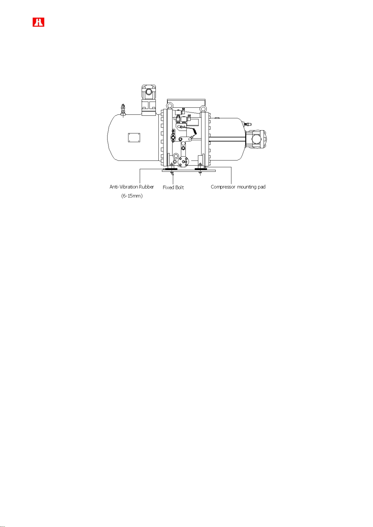
The compressor must be installed horizontally and in order to prevent excessive vibration transferred by the
structure and piping of the chiller while in operation, the cushion or anti-vibration pad should be installed. The
installation of the anti-vibration pad is shown in the figure below. The screws should only be tightened until slight
deformation of the rubber pad is visible.
Attention on the compressor piping works
The unsuitable piping works done to the compressor could cause abnormal vibration and noise which might
damage the compressor. Take notice to the following points to prevent this situation:
1. Cleanliness of the system should be kept after welding the piping to avoid any swarf or debris contained inside
the system as it may cause serious damage to the compressor during operation.
2. In order to reduce the vibration on the piping tubes, it is recommended to use copper tube to be the suction and
discharge piping tubes. Copper tubes are better to minimize the vibration in the piping while the compressor is in
operation. In case steel tubes are used in piping system, then the suitable welding works are very important to
avoid any stress in the piping. This inner stress can cause harmonic vibration and noise which will reduce the
compressor life. If a large-caliber copper tube is not easily accessible and a steel tube is used instead in suction
port, Hanbell recommends using a copper tube in discharge port to minimize abnormal vibration and noise.
3. Remove the oxidized impurities, swarf or debris caused by welding in the piping tubes. If these foreign matters
are sunk into the compressor, the oil filter might be clogged resulting in the malfunctioning of lubrication system,
bearings and capacity control system.
4. Suction and discharge flanges are forged steel and it can be welded directly with piping connectors. After
welding the flanges and pipes, it must be cooled down by ambient air. Do not use water to cool it down. Water
quenching is prohibited.
Page 44
43
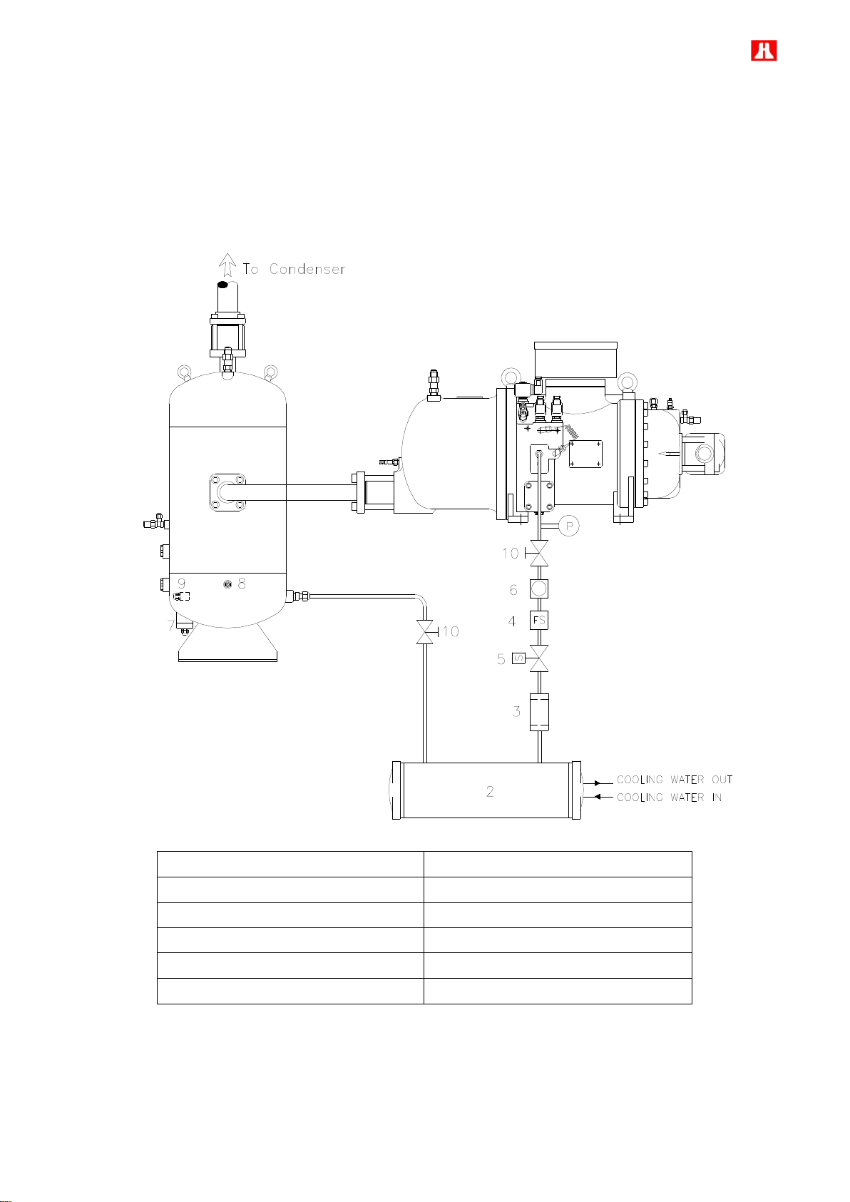
Model : RC2-100F、RC2-140F、RC2-180F
1. External oil separator
7. Oil level switch
2. Oil cooler
8. Oil temperature sensor
3. Oil filter
9. Oil heater
4. Lubricant flow switch
10. Stop valve
5. Solenoid valve
11. Compressor
6. Sight glass
(1) Installation of lubricant circuit
To obtain high oil filtering efficiency, low pressure drop and non-interruption with lubricant supply system, the oil
separator is built outside the compressor. The installation of lubricant circuit is a very important issue during the
installation of the compressor. So before starting, make sure to read carefully all the instructions contain inside
this manual, and make sure that each step is done in accordance with the specification.
Note:Please refer to the selection software for the capacity of liquid injection or oil cooler and following
recommendation to install oil cooler, oil injection system and economizer.
Page 45

44
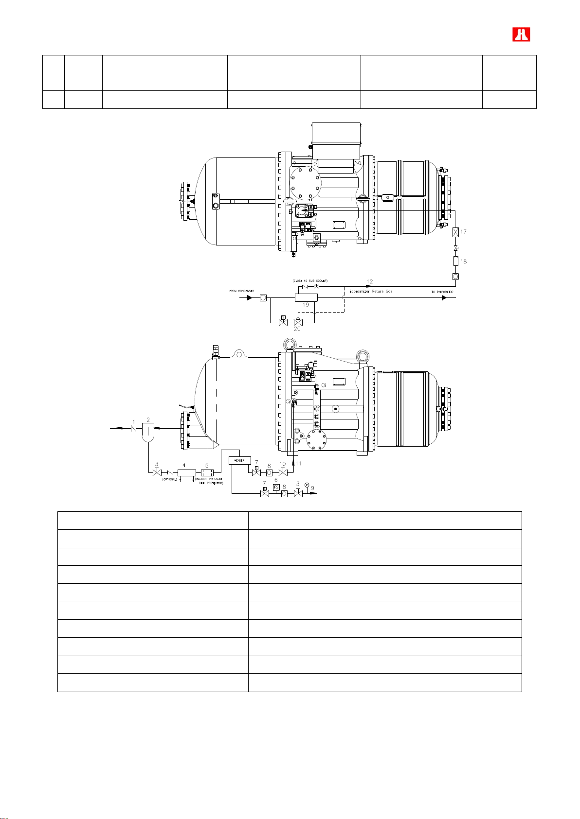
Item
Oil
cooler
Oil injection into
compression chamber
Liquid injection into
compression chamber
Liquid injection for cooling
motor winding
Economizer
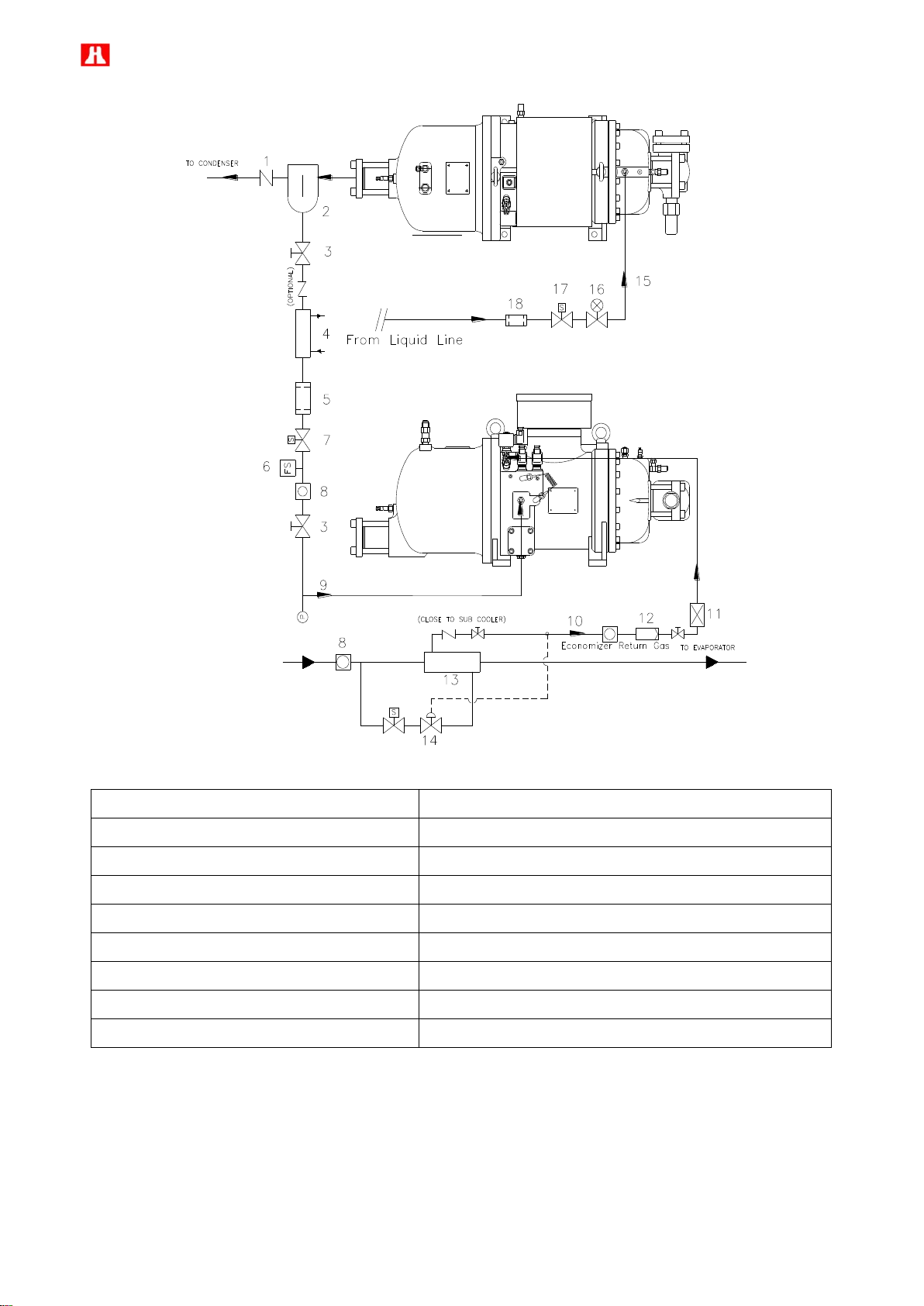
A
-
- - -
O
Ci
Oi
Ei
Li
1. Check valve
8. To principal return oil port Oi
2. External oil separator
9. To medium pressure (Economizer return port) Ei
3. Stop valve
10. Oil cooler
4. Oil filter
11. Muffler
5. Lubricant flow switch
12. Suction strainer
6. Oil solenoid valve
13. Expansion valve
7. Sight glass
14. Sub-cooler
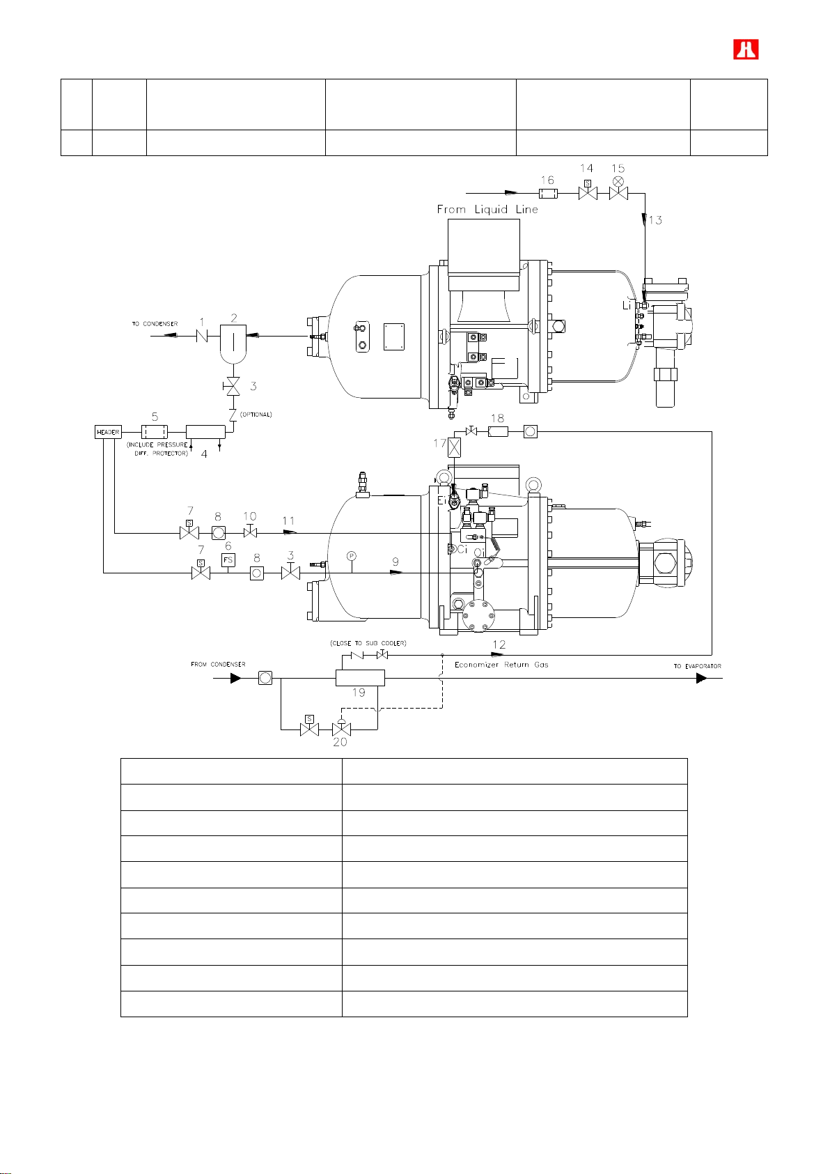
(2) Lubricant circuit, Liquid injection system and economizer connection diagram
Page 46

45
Item
Oil
cooler
Oil injection into
compression chamber
Liquid injection into
compression chamber
Liquid injection for cooling
motor winding
Economizer
B
O
O - O
O
Ci
Oi
Ei
Li
Page 47

46
It
Oil
cooler
Oil injection into
compression chamber
Liquid injection into
compression chamber
Liquid injection for cooling
motor winding
Economizer
C
O
-
O
O
O
1. Check valve
11. Cooling compressor’s chamber port Ci
2. External oil separator
12. To medium pressure (economizer return port) Ei
3. Stop valve
13. Liquid injection to motor winding port Li
4. Oil cooler
14. Liquid injection solenoid valve
5. Oil filter
15. Liquid injection expansion valve
6. Oil flow switch
16. Liquid line filter
7. Oil solenoid valve
17. Muffler
8. Sight glass
18. Strainer
9. To principal oil return port Oi
19. Sub-cooler
10. Adjustable flow valve
20. Expansion valve
Page 48

47
Ci
Oi
Ei
Li
1. Check valve
12. To cooling down compression chamber port Ci
2. External oil separator
13. Liquid line filter
3. Stop valve
14. Liquid injection to motor winding port Li
4. Oil cooler
15. Liquid injection solenoid valve
5. Oil filter
16. Liquid injection expansion valve
6. Lubricant flow switch
17. Liquid line filter
7. Oil solenoid valve
18. To medium pressure (economizer return port) Ei
8. Sight glass
19. Muffler
9. To principal return oil port
20. Strainer
10. Liquid injection solenoid valve
21. Sub-cooler
11. Liquid injection expansion valve
22. Expansion valve
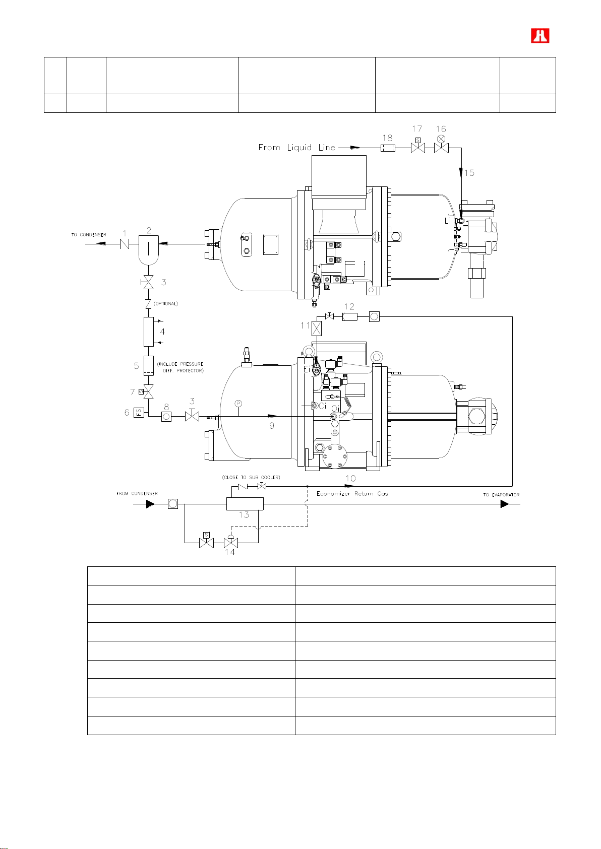
Item
Oil
cooler
Oil injection into
compression chamber
Liquid injection into
compression chamber
Liquid injection for cooling
motor winding
Economizer
D
O
-
-
O
O
Page 49
48
1. Check valve
10. To medium pressure (economizer return port) Ei
2. External oil separator
11. Muffler
3. Stop valve
12. Strainer
4. Oil cooler
13. Sub-cooler
5. Oil filter
14. Expansion valve
6. Lubricant flow switch
15. Liquid injection to motor winding port Li
7. Oil solenoid valve
16. Liquid injection to expansion valve
8. Sight glass
17. Liquid injection to solenoid valve
9. To principal return oil port Oi
18. Liquid line filter
Ci
Oi
Ei
Li
Page 50
49
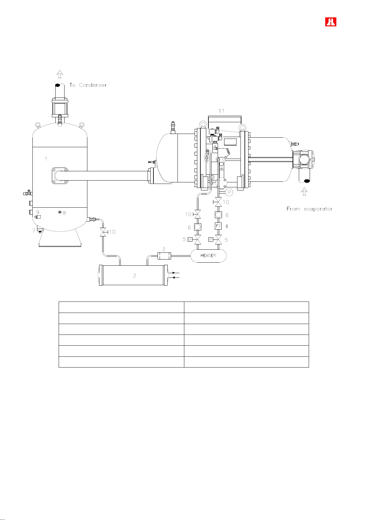
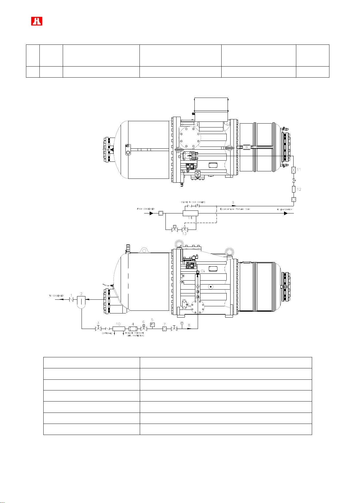
Model : RC2-200F ~ RC2-620F
1. External oil separator
7. Oil level switch
2. Oil cooler
8. Oil temperature sensor
3. Oil filter and cartridge
9. Oil heater
4. Lubricant flow switch
10. Manually adjustable flow valve
5. Oil solenoid valve
11. Compressor
6. Sight glass
(1) Installation of lubricant circuit
Page 51
50
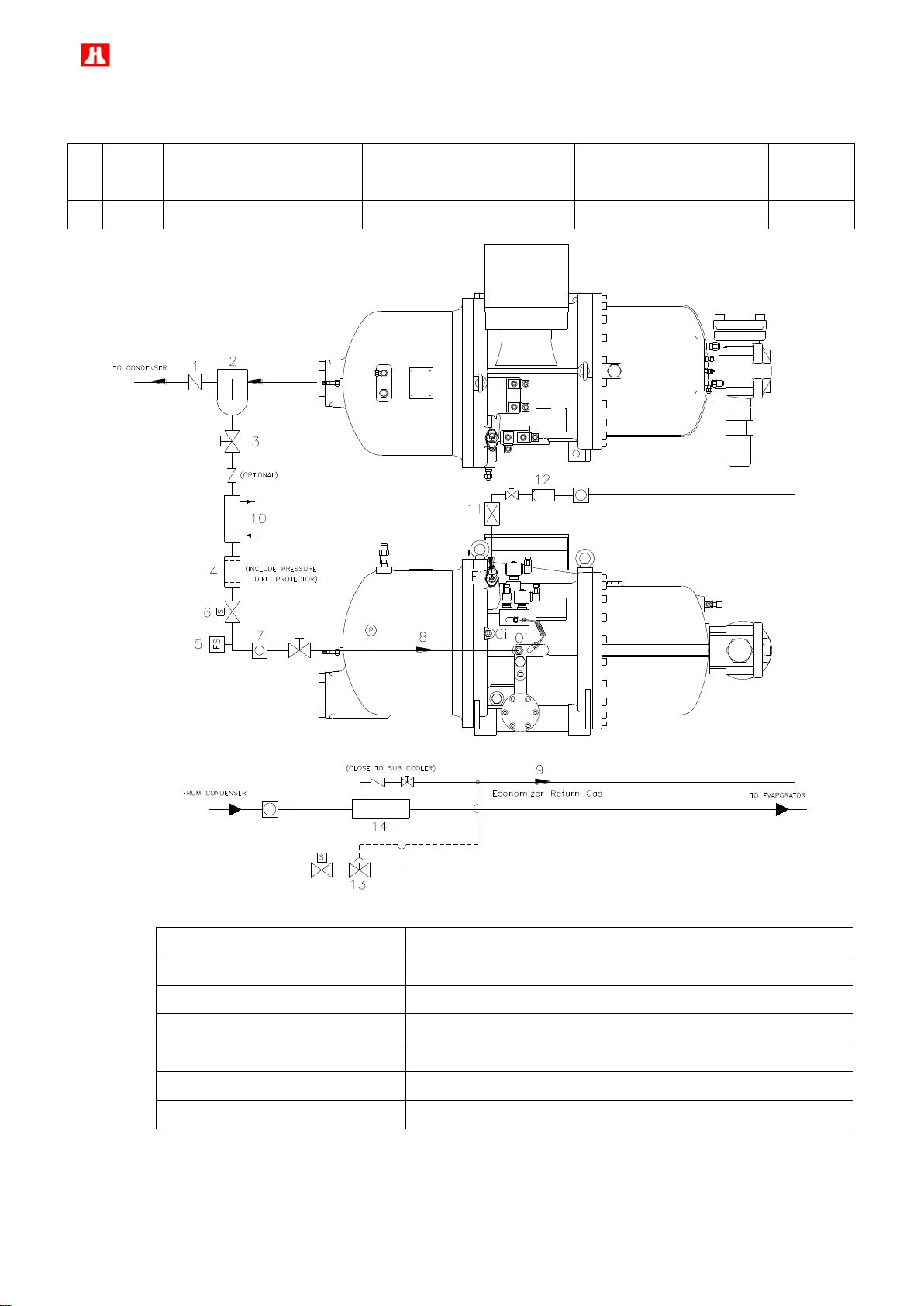
Item
Oil
cooler
Oil injection into
compression chamber
Liquid injection into
compression chamber
Liquid injection for cooling
motor winding
Economizer
A
-
- - -
O
1. Check valve
8. To principal return oil port Oi
2. External oil separator
9. To medium pressure (Economizer return port) Ei
3. Stop valve
10. Oil cooler
4. Oil filter
11. Muffler
5. Lubricant flow switch
12. Suction strainer
6. Oil solenoid valve
13. Expansion valve
7. Sight glass
14. Sub-cooler
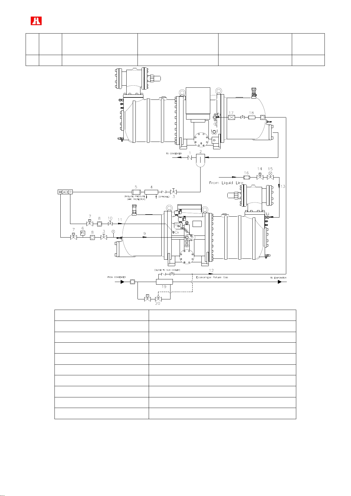
(2) Lubricant circuit, Liquid injection system and economizer connection diagram
Page 52
51
Item
Oil
cooler
Oil injection into
compression chamber
Liquid injection into
compression chamber
Liquid injection for cooling
motor winding
Economizer
B
O
O - O
O
1. Check valve
11. Cooling compressor’s chamber port Ci
2. External oil separator
12. To medium pressure (economizer return port) Ei
3. Stop valve
13. Liquid injection to motor winding port Li
4. Oil cooler
14. Liquid injection solenoid valve
5. Oil filter
15. Liquid injection expansion valve
6. Oil flow switch
16. Liquid line filter
7. Oil solenoid valve
17. Muffler
8. Sight glass
18. Strainer
9. To principal oil return port Oi
19. Sub-cooler
10. Adjustable flow valve
20. Expansion valve
Page 53

52
Item
Oil cooler
Oil injection into
compression chamber
Liquid injection into
compression chamber
Liquid injection for cooling
motor winding
Economizer
C
O - O
O
O
1. Check valve
12. To cooling down compression chamber port Ci
2. External oil separator
13. Liquid line filter
3. Stop valve
14. Liquid injection to motor winding port Li
4. Oil cooler
15. Liquid injection solenoid valve
5. Oil filter
16. Liquid injection expansion valve
6. Lubricant flow switch
17. Liquid line filter
7. Oil solenoid valve
18. To medium pressure (economizer return port) Ei
8. Sight glass
19. Muffler
9. To principal return oil port
20. Strainer
10. Liquid injection solenoid valve
21. Sub-cooler
11. Liquid injection expansion valve
22. Expansion valve
Page 54
53
Item
Oil
cooler
Oil injection into
compression chamber
Liquid injection into
compression chamber
Liquid injection for cooling
motor winding
Economizer
D
O
-
-
O
O
1. Check valve
10. To medium pressure (economizer return port) Ei
2. External oil separator
11. Muffler
3. Stop valve
12. Strainer
4. Oil cooler
13. Sub-cooler
5. Oil filter
14. Expansion valve
6. Lubricant flow switch
15. Liquid injection to motor winding port Li
7. Oil solenoid valve
16. Liquid injection to expansion valve
8. Sight glass
17. Liquid injection to solenoid valve
9. To principal return oil port Oi
18. Liquid line filter
Page 55

54
1. External oil separator
7. Oil level switch
2. Oil cooler
8. Oil temperature sensor
3. Oil filter and cartridge
9. Oil heater
4. Lubricant flow switch
10. Manually adjustable flow valve
5. Oil solenoid valve
11. Compressor
6. Sight glass
Model : RC2-710F ~ RC2-930F
(1) Installation of lubricant circuit
Page 56

55
(2) Lubricant circuit, Liquid injection system and economizer connection diagram
Item
Oil
cooler
Oil injection into
compression chamber
Liquid injection into
compression chamber
Liquid injection for cooling
motor winding
Economizer
A
-
- - -
O
1. Check valve
8. To principal return oil port Oi
2. External oil separator
9. To medium pressure (Economizer return port) Ei
3. Stop valve
10. Oil cooler
4. Oil filter
11. Muffler
5. Lubricant flow switch
12. Suction strainer
6. Oil solenoid valve
13. Expansion valve
7. Sight glass
14. Sub-cooler
Page 57
56
Item
Oil
cooler
Oil injection into
compression chamber
Liquid injection into
compression chamber
Liquid injection for cooling
motor winding
Economizer
B
O
O - O
O
1. Check valve
11. Cooling compressor’s chamber port Ci
2. External oil separator
12. To medium pressure (economizer return port) Ei
3. Stop valve
13. Liquid injection to motor winding port Li
4. Oil cooler
14. Liquid injection solenoid valve
5. Oil filter
15. Liquid injection expansion valve
6. Oil flow switch
16. Liquid line filter
7. Oil solenoid valve
17. Muffler
8. Sight glass
18. Strainer
9. To principal oil return port Oi
19. Sub-cooler
10. Adjustable flow valve
20. Expansion valve
Page 58

57
Item
Oil cooler
Oil injection into
compression chamber
Liquid injection into
compression chamber
Liquid injection for cooling
motor winding
Economizer
C
O - O
O
O
1. Check valve
12. To cooling down compression chamber port Ci
2. External oil separator
13. Liquid line filter
3. Stop valve
14. Liquid injection to motor winding port Li
4. Oil cooler
15. Liquid injection solenoid valve
5. Oil filter
16. Liquid injection expansion valve
6. Lubricant flow switch
17. Liquid line filter
7. Oil solenoid valve
18. To medium pressure (economizer return port) Ei
8. Sight glass
19. Muffler
9. To principal return oil port
20. Strainer
10. Liquid injection solenoid valve
21. Sub-cooler
11. Liquid injection expansion valve
22. Expansion valve
Page 59

58
Item
Oil
cooler
Oil injection into
compression chamber
Liquid injection into
compression chamber
Liquid injection for cooling
motor winding
Economizer
D
O
-
-
O
O
1. Check valve
10. To medium pressure (economizer return port) Ei
2. External oil separator
11. Muffler
3. Stop valve
12. Strainer
4. Oil cooler
13. Sub-cooler
5. Oil filter
14. Expansion valve
6. Lubricant flow switch
15. Liquid injection to motor winding port Li
7. Oil solenoid valve
16. Liquid injection to expansion valve
8. Sight glass
17. Liquid injection to solenoid valve
9. To principal return oil port Oi
18. Liquid line filter
Page 60

59
Model : RC2-1020F ~ RC2-1530F
1. External oil separator
7. Oil level switch
2. Oil cooler
8. Oil temperature sensor
3. Oil filter and cartridge
9. Oil heater
4. Lubricant flow switch
10. Manually adjustable flow valve
5. Oil solenoid valve
11. Compressor
6. Sight glass
(1) Installation of lubricant circuit
Page 61
60
Item
Oil
cooler
Oil injection into
compression chamber
Liquid injection into
compression chamber
Liquid injection for cooling
motor winding
Economizer
A
-
- - -
O
1. Check valve
7. To principal return oil port Oi
2. External oil separator
8. To medium pressure (Economizer return port) Ei
3. Stop valve
9. Oil cooler
4. Oil filter
10. Muffler
5. Lubricant flow switch
11. Suction strainer
6. Oil solenoid valve
12. Expansion valve
7. Sight glass
13. Sub-cooler
(2) Lubricant circuit, Liquid injection system and economizer connection diagram
Page 62
61
Item
Oil
cooler
Oil injection into
compression chamber
Liquid injection into
compression chamber
Liquid injection for cooling
motor winding
Economizer
B
O
O - O
O
1. Check valve
11. Cooling compressor’s chamber port Ci
2. External oil separator
12. To medium pressure (economizer return port) Ei
3. Stop valve
13. Liquid injection to motor winding port Li
4. Oil cooler
14. Liquid injection solenoid valve
5. Oil filter
15. Liquid injection expansion valve
6. Oil flow switch
16. Liquid line filter
7. Oil solenoid valve
17. Muffler
8. Sight glass
18. Strainer
9. To principal oil return port Oi
19. Sub-cooler
10. Adjustable flow valve
20. Expansion valve
Page 63

62
Item
Oil cooler
Oil injection into
compression chamber
Liquid injection into
compression chamber
Liquid injection for cooling
motor winding
Economizer
C
O
-
O
O
O
1. Check valve
12. To cooling down compression chamber port Ci
2. External oil separator
13. Liquid line filter
3. Stop valve
14. Liquid injection to motor winding port Li
4. Oil cooler
15. Liquid injection solenoid valve
5. Oil filter
16. Liquid injection expansion valve
6. Lubricant flow switch
17. Liquid line filter
7. Oil solenoid valve
18. To medium pressure (economizer return port) Ei
8. Sight glass
19. Muffler
9. To principal return oil port
20. Strainer
10. Liquid injection solenoid valve
21. Sub-cooler
11. Liquid injection expansion valve
22. Expansion valve
Page 64
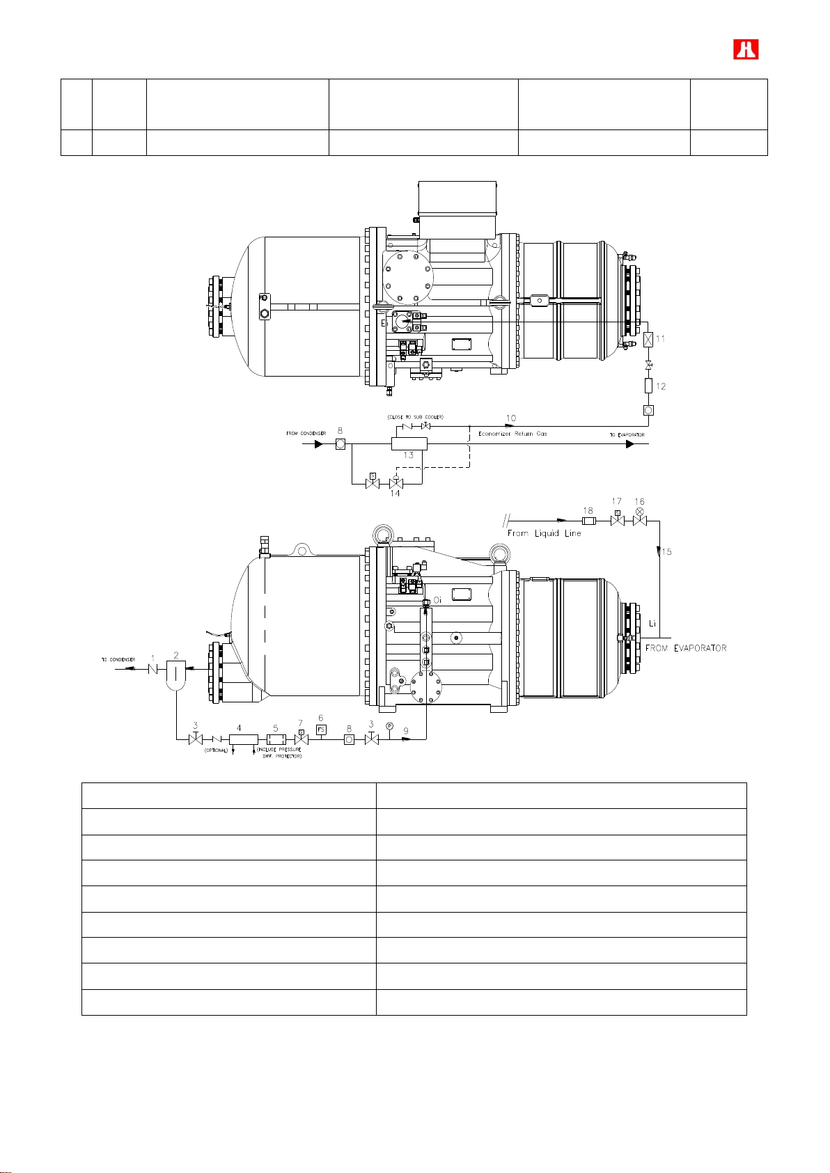
63
Item
Oil
cooler
Oil injection into
compression chamber
Liquid injection into
compression chamber
Liquid injection for cooling
motor winding
Economizer
D
O
-
-
O
O
1. Check valve
10. To medium pressure (economizer return port) Ei
2. External oil separator
11. Muffler
3. Stop valve
12. Strainer
4. Oil cooler
13. Sub-cooler
5. Oil filter
14. Expansion valve
6. Lubricant flow switch
15. Liquid injection to motor winding port Li
7. Oil solenoid valve
16. Liquid injection to expansion valve
8. Sight glass
17. Liquid injection to solenoid valve
9. To principal return oil port Oi
18. Liquid line filter
Page 65

64
smm /
2
4. Lubricant
The main functions of the lubrication oil in the screw compressor are lubrication, internal sealing, cooling,
silencing and capacity control. The positive oil pressure in the cylinder pushes the piston and the slide valve which
are connected by a piston rod to move forward and backward in the compression chamber. The design with
positive pressure differential lubrication system in the RC2-F series is available to omit an extra oil pump in most
of applications. However, in some special applications (Pd-Ps<4 bar), it is still necessary to install an extra oil
pump to the compressor for safety.
Bearings used in RC2-F compressor require a small but steady quantity of oil for lubrication; the oil injection into
the compression chamber creates an oil sealing film between screw rotors which secures the volumetric efficiency
and absorbs a part of compression heat. In order to separate the oil from the refrigerant or gas, an oil separator is
required to ensure the least amount of oil carried into system. High oil carryover to the system will reduce the heat
exchanger performance or simply block the pipe. For synthetic oil, it has high tendency to react with water, acid
and metal particle and generates slurry. Compressor operates without sufficient oil supply will lead to high
discharge temperature, bearing failure or screw rotor jam. Pay more attention to the oil temperature, which has a
very significant factor to the compressor’s bearing life. High oil temperature will reduce the oil viscosity and cause
the poor lubrication and heat absorption in the compressor as well. Too much refrigerant dissolved in the oil will
also reduce the oil viscosity which might become the root cause of bearing failure in the future. The oil viscosity is
recommended at 10
condition(low evaporating temperature/high condensing temperature), an extra oil cooler will be needed.
High viscosity oil is recommended to be applied in the strict working condition (heat pump/ air-cooled). User
should take notice on the oil level in the oil separator because if the oil return from the evaporator is less than the
oil carryover to the system from oil separator, the oil separator will loss oil gradually and comes to the system stop
in the end. Therefore, when users find oil return problem in the system, a fine oil separator is highly recommended
to be installed between the oil separator discharge port and condenser. Flooded chiller or DX type chiller with long
distance piping is also recommended to be installed with a fine oil separator to reduce the oil carryover into
system.
Low viscosity oil is recommended to be applied in the low evaporating temperature (SST< -20℃). Selecting an oil
which can maintain at least 10 cSt for its viscosity under operating. Miscibility of oil with refrigerant is usually an
important index for the selection of oil. The oil with good miscibility with refrigerant should have low miscibility
at any temperature. If the compressor operates under the critical working
value at high working temperature and high miscibility value at low working temperature to ensure the oil viscosity
not declined too much at different working condition.
4.1 Pre-cautions in changing of oil
The following points should be noted to ensure good oil characteristics:
1. Use only qualified oil and do not mix different brand of oil together. Different kinds of refrigerant should match
different kinds of oil, note that some synthetic oil are incompatible with mineral oil.
Page 66

65
2. For the chiller system using synthetic oil, make sure not to expose the oil to atmosphere for a long time. It is
necessary to vacuum the system completely when installing the compressor.
3. If the customer wants to use special type of oil, confirm with the compressor manufacturer is necessary.
4. In order to vaporize the water in the system, it is suggested to heat the system and vacuum the system as long
as possible after changing of new oil in the system
5. If the system encounters a compressor motor burned, the acidity debris will remain inside the system, so follow
the procedures mentioned above to overhaul the system is necessary. It is also important to check the oil acidity
after 72 hours operation and change it again until the oil acidity is within the standard value.
4.2 Changing of oil
Lubrication oil is one of the most important factor to the compressor system in order to maintain the good
operation, lubrication, cooling, sealing and capacity control. The following points should be taken into
consideration to ensure good oil management.
1. Oil contamination caused by debris or swarf might clog the oil filter and cause compressor bearing failure. In
order to prevent the clogging of oil filter, an optional pressure differential switch is recommended to be installed.
The switch will trip when the oil pressure differential reaches the setting point. The compressor will shut down
automatically to prevent the bearing away from getting damage by lacking of lubrication.
2. Acidified system due to the moisture will cause the reduction of bearing and motor’s life. Check the oil acidity
periodically and change the oil if the oil acidity value is lower than PH6. Change the deteriorated dryer periodically
if possible to keep the system dryness. Refer to the oil changing procedure especially after overhauling the
system due to motor burned out, check the oil quality monthly or periodically and change the oil if the oil is out of
standard specs. It is necessary to take care of the oil quality and system cleanliness and dryness periodically.
3. Compressor running at high discharge temperature for a long time will cause the change of oil property and
short the bearing life. If the compressor’s discharge temperature keeps at high stage (approaching the critical
point) then the oil will spoil gradually in a short time. Check the oil characteristic every 2 months if possible. It is
necessary to change the oil if the characteristics of the oil are out of the specification. In case if the oil
characteristics cannot be checked periodically, change the oil after 1 years of operation. For the first operation of
the compressor, it is recommended to check oil and clean oil filter after running 200 hours. Because the piping
debris or swarf could be accumulated inside the system after continuous operation, it is necessary to check the oil
after 2,000 hours or after 6 months of running. Good oil management can ensure the system operating under
good condition.
Page 67
66
SPECIFICATION
UNITS
HBR -B10
HBR -A02
HBR -A04
HBR -B09
HBR -B02
HBR -B01
COLOR, ASTM
1.5
L1.0
L1.0
SPECIFIC GRAVITY
0.883
0.914
0.925
0.95
1.01
1.05
VISCOSITY
40℃
mm2/s (cSt)
56.0
54.5
96.5
175
168
298
100℃
7.0
6.07
8.12
16.5
20.2
32.0
FLASH POINT
℃
220
188
198
265
290
271
POUR POINT
℃
-40
-35
-25
-30
-43
-35
T.A.N
mg KOH/g
0.01
0.00
0.01
COPPER STRIP
100℃/3hr
1a
1a
1a
MOISTURE
ppm
15
20
20
FLOC POINT
℃
-75
-45
-35
DIELETRIC STRENGTH
(2.5mm)
kV
75
50
50
46.6
SPECIFICATION
UNITS
HBR -B05
HBR -B08
HBR -B09
HBR -B04
COLOR, ASTM
SPECIFIC GRAVITY
0.945
0.94
0.95
0.95
VISCOSITY
40℃
mm2/s (cSt)
64
131
175
215.9
100℃
8.9
14.53
16.5
20.8
FLASH POINT
℃
266
254
265
271
POUR POINT
℃
-43
-36.5
-30
-25
T.A.N
mg KOH/g
COPPER STRIP
100℃/3hr
MOISTURE
ppm
FLOC POINT
℃
DIELETRIC STRENGTH
2.5mm
kV
46.6
4.3 Lubricants table
Applicable oil types (R22)
Applicable oil types (R134a, R404A, R407C, R507)
Page 68

67
5. Electrical data and design
Full load Amper
Starting Current
Time
I
Y- shift time 0.25~0.5msec
5.1 Motor design
HANBELL RC2-F series screw compressors are fitted with Y-Δ motor as standard. But Δ/ΔΔ motor (Part Winding
Starting – PWS) is also available for model RC2-100F ~ RC2-580F.
i.e.
● RC2-100F ~ RC2-580F both Y-Δ motor and Δ/ΔΔ motor are available.
● RC2-620F ~ RC2-1530F only Y-Δ motor are available.
Y-Δ Starting
Y-Δ motor connects motor coil by Y connection during starting therefore reducing voltage on coils to 1/√3 of input
voltage and reconnects motor coil by △ connection after starting. By doing so, we can decrease starting current
thorough voltage drop, i.e., so-called voltage-drop starting.
In Y connection, MCM、MCS are inductive while motor leads Z,X,Y are tied together as a neutral connecting as Y
fashion. A few seconds later ( 3 ~ 5 sec is recommended), MCM, MCS become deductive. Around 0.25 sec later,
MCM,MCD are inductive,it turns out △ run connection. Y-Δ motor connection method is shown in the following
motor wiring diagram:
Please pay attention : After Y start,MCM & MCS are deductive for 0.25msec and then MCM & MCD are inductive
for Δ run. Within as transient as 0.25msec, pseudo short circuit might occur due to inappropriate action of
contactors, causing trip of compressors. When it occurs, we recommend usage of adjustable Y-Δ dedicated Timer
or slightly lengthen span of time for MCM, MCS deduction - MCM,MCD re-induction from 0.25 msec to 0.5 msec
max directly in micro controller or PLC program. Please refer to Y-Δ shift time diagram for details. Because motor
is not powered during Y-Δ shift, shorter Y-Δ shift span is suggested to prevent second start due to decreased
rotation speed. However, if Y-Δ shift span is too short, aforementioned pseudo short circuit might occur.
Page 69

68
Full load Amper
Starting Current
Time
I
(AMP)
sec
PW2:7,8,9
B:Pt100Ω / Pt1000Ω
(Option)
PW1:1,2,3
93
A:PTC
2 8
Earth Bolt
71
A
B
Y-Δ Starting features
1. Starting current in Y connection is 1/3 of lock rotor ampere.
2. Starting torque in Y connection is 1/3 of lock rotor torque.
3. Acceleration of motor rotor becomes smaller at full-load starting,,therefore compressors require starting at
partial load.
Δ/ΔΔ (PW) starting
RC2-100F ~ RC2-580F are available to be fitted with PWS motor for customer’s application as an optional
accessory。
Please refer to the follow diagram for the wiring of PWS motor.
The selection of both of the motor contactors (k1 / k2) is each for approx. 60% of the max. running current. The
recommended time delay of the switching relay k1 is to be set at 0.5 second and not more than 1 second.
Page 70

69
PWS Starting features
A:PTC
B:Pt100Ω / Pt1000Ω
Earth Bolt
W
V
U
(Option)
Y
X
Z
A
B
Protection device
Set point
Remark
Motor wiring temperature protector (PTC sensor)
Cutout 120℃, Cut in 75℃
Standard
Discharge temperature protector (PTC sensor )
Cutout 110℃, Cut in 60℃
Standard
Phase reversal protector (INT69 HBY)
Optional
Phase failure protector (INT69 HBY)
Optional
Oil level switch
Optional
Oil filter pressure differential switch
Cutout 2.5Kg/cm2G
Optional
Oil flow switch
Optional
PT100Ω or PT1000Ω for liquid injection to motor chamber.
Solenoid valve open 85℃ , Solenoid valve close 75℃
Optional
1. The starting current is around 40% ~ 70% of full-winding Locked Rotor Current. It depends on the design and
motor size.
2. Low starting torque.
Direct On Line start
Besides Y-Δ and PWS start, if there were any inquiry of Direct on line start、Soft start、Inverter start or Series
reactance reduced voltage start, please contact Hanbell for further.
5.2 Compressor protection devices
The table below shows the list of protection devices which are essential to protect the compressor and operate
safely. Follow the protection devices listed in the below table to ensure the compressor running under normal
condition.
The motor thermister and discharge thermister are the temperature sensors with quick response while the
temperature approach to their set point; the thermisters must be connected in series to a controller (INT69HBY) in
terminal box as a guardian to protect the compressor. Alarm lamp for this protector is required to be embedded on
the control panel as indicator. Any intention to short the controller for startup the compressor is prohibited
especially in Hanbell. It is beyond Hanbell’s responsibility to keep the warrantee of compressor if there is any
above action found.
5.3 Power supply
Page 71

70
(maximum voltage deviation from average voltage)
(average voltage)
1. Limitation of supply power
a. Voltage limitation
Long term running : rated voltage ±5%
Instant running : rated voltage ±10%
b. Frequency : Rated frequency ±2%
Note that in the region where the electricity power is unstable, install an additional Hi-Low voltage protector
with ± 5% under and over tolerance outside the normal voltage to ensure the safe running of the compressor.
2. Unbalanced voltages :
Unbalanced voltages usually occur because of variations in the load. When the load on one or more of the
phases is different than the other(s), unbalanced voltages will appear. This can be due to different
impedances, or type and value of loading on each phase. Unbalanced voltages can cause serious problems,
particularly to motor.
NEMA defines voltage unbalance as follows :
Percent voltage unbalance = 100 x
NEMA states that polyphase motors shall operate successfully under running conditions at rated load when
voltage unbalance at the motor terminals does not exceed 1%. Further, operation of a motor with above a 5%
unbalance condition is not recommended, and will probably result in damage to the motor.
Unbalanced voltages at motor terminals cause phase current unbalance ranging from 6 to 10 times the
percent voltage unbalance for a fully loaded motor. This causes motor over current resulting in excessive heat
that shortens motor life, and hence, eventual motor burnout. If the voltage unbalance is great enough, the
reduced torque capability might not be adequate for the application and the motor will not attain reated speed.
Some of the more common causes of unbalance voltages are :
Unbalanced incoming utility supply
Unequal transformer tap settings
Large single phase distribution transformer on the system.
Open phase on the primary of a 3 phase transformer on the distribution system
Faults or grounds in the power transformer
Open delta connected transformer banks
A blow fuse on 3 phase bank of power factor improvement capacitors
Unequal impedance in conductors of power supply wiring
Unbalanced distribution of single phase loads such as lighting
Heavy reactive single phase loads such as welders
An 3 phase unbalanced voltages protector is upon request as optional accessory. Please contact with Hanbell
Page 72

71
2 8
(Option)
A:PTC
B:Pt100Ω / Pt1000Ω
PW2:7,8,9
PW1:1,2,3
3 9
Earth Bolt
1 7
B
A
Grounding Terminal
for more detail.
5.4 Selection of magnetic contactor
Please refer to AC3 specification, compressor selection program and design conditions of system to choose suitable
contactor.
5.5 Grounding
There’s a grounding terminal inside cable box. Please accurately connect it to grounding of control panel for the
system.
Suggestion:
a. The regular setting of electric leak protection should be greater than 50mA; for a humid location, 25mA is
better.
b. Grounding voltage of casing should be no greater than 50V; for a humid location, the limit is 25V.
c. Grounding resistance should be no greater than 500 Ohm.
d. Air cut board (ACB) is regularly equipped with electric leak protection. Please refer to related settings for its
normal action.
e. If electric leak protection is active, please check if insulation of equipments is normal and if its wiring and
setting are correct. Please make sure nothing is wrong before turning on the power. If there are any questions,
please contact the supplier of equipments.
Page 73

72
Model
RC2 - F
&
Accessory
100
140
180
200
230
260
300
310
320
340
370
410
430
470
510
550
580
620
710
790
830
930
1020
1130
1270
1530
Steps or Step-less capacity control system
● ● ● ● ● ● ● ● ● ● ● ● ● ● ● ● ● ● ● ● ● ● ● ● ● ● Compatible Steps& step-less capacity control system
△ △ △ △ △ △ △ △ △ △ △ △ △ △ △ △ △ △ △ △ △ △ △ △ △
△
Discharge check valve
● ● ● ● ● ● ● ● ● ● ● ● ● ● ● ● ● ● ● ● ● ● ● ● ● ● Suction & discharge connection bushings
● ● ● ● ● ● ● ● ● ● ● ● ● ● ● ● ● ● ● ● ● ● ● ● ●
●
Suction & discharge stop valves
△ △ △ △ △ △ △ △ △ △ △ △ △ △ △ △ △ △ △ △ △ △ △ △ △
△
PTC temp. sensor
● ● ● ● ● ● ● ● ● ● ● ● ● ● ● ● ● ● ● ● ● ● ● ● ●
●
INT69HBY controller
● ● ● ● ● ● ● ● ● ● ● ● ● ● ● ● ● ● ● ● ● ● ● ● ●
●
IP54 cable box
● ● ● ● ● ● ● ● ● ● ● ● ● ● ● ● ● ● ● ● ● ● ● ● ●
●
Oil drain valve
△ △ △ △ △ △ △ △ △ △ △ △ △ △ △ △ △ △ △ △ △ △ △ △ △
△
Liquid injection system (solenoid valve + expansion valve)
△ △ △ △ △ △ △ △ △ △ △ △ △ △ △ △ △ △ △ △ △ △ △ △ △
△
Liquid injection system (solenoid valve + stop valve)
△ △ △ △ △ △ △ △ △ △ △ △ △ △ △ △ △ △ △ △ △ △ △ △ △
△
Horizontal check valve
△ △ △ △ △ △ △ △ △ △ △ △ △ △ △ △ △ △ △ △ △ △ △ △ △
△
External oil separator
△ △ △ △ △ △ △ △ △ △ △ △ △ △ △ △ △ △ △ △ △ △ △ △ △
△
External oil filter
△ △ △ △ △ △ △ △ △ △ △ △ △ △ △ △ △ △ △ △ △ △ △ △ △
△
Oil flow switch
△ △ △ △ △ △ △ △ △ △ △ △ △ △ △ △ △ △ △ △ △ △ △ △ △
△
Economizer
△ △ △ △ △ △ △ △ △ △ △ △ △ △ △ △ △ △ △ △ △ △ △ △ △
△
Economizer connection stop valve
△ △ △ △ △ △ △ △ △ △ △ △ △ △ △ △ △ △ △ △ △ △ △ △ △
△
Oil cooler
△ △ △ △ △ △ △ △ △ △ △ △ △ △ △ △ △ △ △ △ △ △ △ △ △
△
Oil pump
△ △ △ △ △ △ △ △ △ △ △ △ △ △ △ △ △ △ △ △ △ △ △ △ △
△
Oil filter pressure differential switch connector
△ △ △ △ △ △ △ △ △ △ △ △ △ △ △ △ △ △ △ △ △ △ △ △ △
△
Safety valve
△ △ △ △ △ △ △ △ △ △ △ △ △ △ △ △ △ △ △ △ △ △ △ △ △
△
Explosion proof accessories
△ △ △ △ △ △ △ △ △ △ △ △ △ △ △ △ △ △ △ △ △ △ △ △ △
△
Mounting pad
△ △ △ △ △ △ △ △ △ △ △ △ △ △ △ △ △ △ △ △ △ △ △ △ △
△
Lubricant oil
△ △ △ △ △ △ △ △ △ △ △ △ △ △ △ △ △ △ △ △ △ △ △ △ △
△
Micro controller
△ △ △ △ △ △ △ △ △ △ △ △ △ △ △ △ △ △ △ △ △ △ △ △ △
△
Sound jacket
△ △ △ △ △ △ △ △ △ △ △ △ △ △ △ △ △ △ △ △ △ △ △ △ △
△
Temperature sensors
△ △ △ △ △ △ △ △ △ △ △ △ △ △ △ △ △ △ △ △ △ △ △ △ △
△
Pt100 or Pt1000 – for motor coil temp. monitoring
6. Compressors accessories
6.1 Compressors standard and optional accessories
●:Standard, △ :Optional, Χ:No need
Note : The accessory chart is just for customers’ reference only. Actual specification and accessories enclosed
might vary with different quotation & agreement. If any optional accessory is required and out of the above
mentioned standard accessory, please contact with Hanbell for detail specification and price of accessory.
Page 74
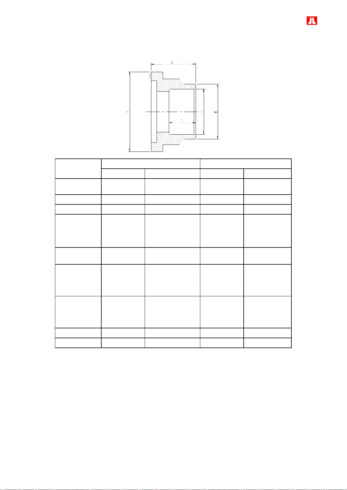
73
6.2 Description of accessories
Model
Standard Discharge Flange Bushing
Standard Suction Flange Bushing
Steel pipe
Copper pipe
Steel pipe
Copper pipe
RC2-100F/140F
1 1/2
1 5/8”
2
2 1/8”
RC2-180F
1 1/2
1 5/8”
2
2 1/8”
RC2-200F
2
2 1/8”
2 1/2
2 5/8”
RC2-230F/260F
RC2-300F/310F
RC2-320F
2 1/2
2 5/8”
3
3 1/8”
RC2-340F/370F
2 1/2
2 5/8”
4
4 1/8”
RC2-410F/430F
RC2-470F/510F
RC2-550F/580F
3
3 1/8”
4
4 1/8”
620F/RC2-710F
790F/RC2-830F
930F
4
4 1/8”
5
5 1/8”
RC2-1020F/1130F
4
4 1/8”
6
N/A
RC2-1270F/1530F
5
5 1/8”
8
N/A
a. Suction and discharge connection bushings
Page 75

74
Model
Discharge / Suction port
Materials and Sizes of pipes
Dimension of flanges bushing
A B C
D
E
RC2-100F
RC2-140F
Discharge
Copper
1 5/8"
50
90
30
41.6
55
2 1/8"
54.3
65
2 5/8"
67
74
Steel
1 1/2"
49.3
60
2"
61.3
74
Suction
Copper
1 5/8"
50
90
30
41.6
55
2 1/8"
54.3
65
2 5/8"
67
74
Steel
1 1/2"
49.3
60
2"
61.3
74
RC2-180F
RC2-200F
Discharge
Copper
1 5/8"
50
90
30
41.6
55
2 1/8"
54.3
65
2 5/8"
67
74
Steel
1 1/2"
49.3
60
2"
61.3
74
Suction
Copper
2 1/8"
60
110
35
54.3
65
2 5/8"
67
77
3 1/8"
79.8
90
Steel
2 1/2"
77.2
90
RC2-230F
RC2-260F
RC2-300F
RC2-310F
RC2-320F
Discharge
Copper
2 1/8"
60
110
35
54.3
65
2 5/8"
67
77
3 1/8"
79.8
90
Steel
2 1/2"
77.2
90
Suction
Copper
2 1/8'
66
120
45
54.3
65
2 5/8"
67
77
3 1/8"
79.8
90
Steel
2 1/2"
77.2
92
3"
90.2
103
RC2-340F
RC2-370F
Discharge
Copper
2 1/8"
60
110
35
54.3
65
2 5/8"
67
77
3 1/8"
79.8
90
Steel
2 1/2"
77.2
90
Suction
Copper
3 1/8"
76
145
50
79.8
87
3 5/8"
92.4
103
4 1/8"
105.1
116
Steel
3"
90.2
105
3 1/2"
102.8
117
4"
115.6
128
RC2-410F
RC2-430F
RC2-470F
RC2-510F
RC2-550F
RC2-580F
Discharge
Copper
2 1/8"
66
120
45
54.3
65
2 5/8"
67
77
3 1/8"
79.8
90
Steel
2 1/2"
77.2
92
3"
90.2
103
Suction
Copper
3 1/8"
7
6
145
50
79.8
90
3 5/8"
92.4
103
4 1/8"
105.1
116
Steel
3"
90.2
105
3 1/2"
102.8
117
4"
115.6
128
RC2-620F
RC2-710F
RC2-790F
RC2-830F
RC2-930F
Discharge
Copper
3 1/8"
7
6
145
50
79.8
90
3 5/8"
92.4
103
4 1/8”
105.1
116
Steel
3
90.2
105
3 1/2"
102.8
117
4"
115.6
128
Suction
Copper
4 1/8"
80
174
35
105.1
121.2
5 1/8"
75
130.5
146.5
Steel
5"
75
141.3
154
RC2-1020F
RC2-1130F
Discharge
Copper
4 1/8”
80
174
35
105.1
121.2
5 1/8”
75
130.5
146.5
Steel
5”
80
141.3
154
Suction
Steel
6”
75
215
40
166.7
196
RC2-1270F
RC2-1530F
Discharge
Steel
6”
75
215
40
166.7
196
Suction
Steel
8”
75
260
40
218
241
Specification and dimension of optional flange bushing
Page 76
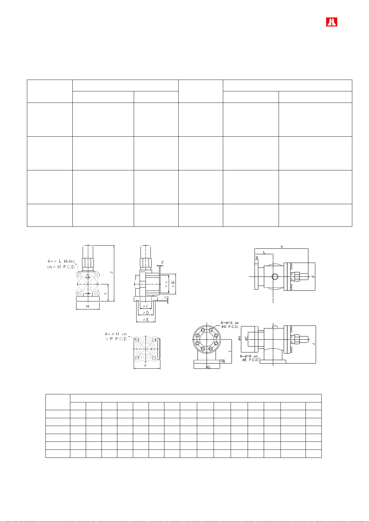
75
b. Suction and discharge stop valves
Model
Stop Valve Size
Model
Stop Valve Size
Discharge
Suction
Discharge
Suction
RC2-100F/140F
2
2
RC2-410F/430F
RC2-470F/510F
RC2-550F/580F
3
4
FC2-180F/200F
2
2 1/2
RC2-620F/710F
RC2-790F/830F
RC2-930F
3
4
RC2-230F/260F
RC2-300F/310F
RC2-320F
2 1/2
3
RC2-1020F
RC2-1130F
4
6
RC2-340F/370F
2 1/2
4
RC2-1270F
RC2-1530F
6
8
Dia.
Dimensions unit: mm
A B C D E F G H I J K L M N P
1 1/2
60
75
36
59
76 6 5
106
75
256
115
18
105
M16x2
105
2”
70
90
60
69
91 6 5
122
86
280
128
18
120
M16x2
120
2 1/2
90
110
67
89
111 6 5
137
95
307
153
18
140
M16x2
140
3
100
120
80
99
121 6 5
154
117
398
177
22
160
M20x2.5
160
4
125
145
105
124
146 6 5
171
130
445
201
22
185
M20x2.5
185
5
30
30
126
194
194
248
230
230
214
338
474
161
--
--
--
For maintenance and service of compressor, it is recommended to install the suction and discharge stop valves.
Please refer to following detail of Hanbell stop valves
Dimensions for 1 1/2”~4” stop valves Dimensions for 5” stop valve
Note: Please contact Hanbell for specification of 6” and 8” stop valves.
Page 77
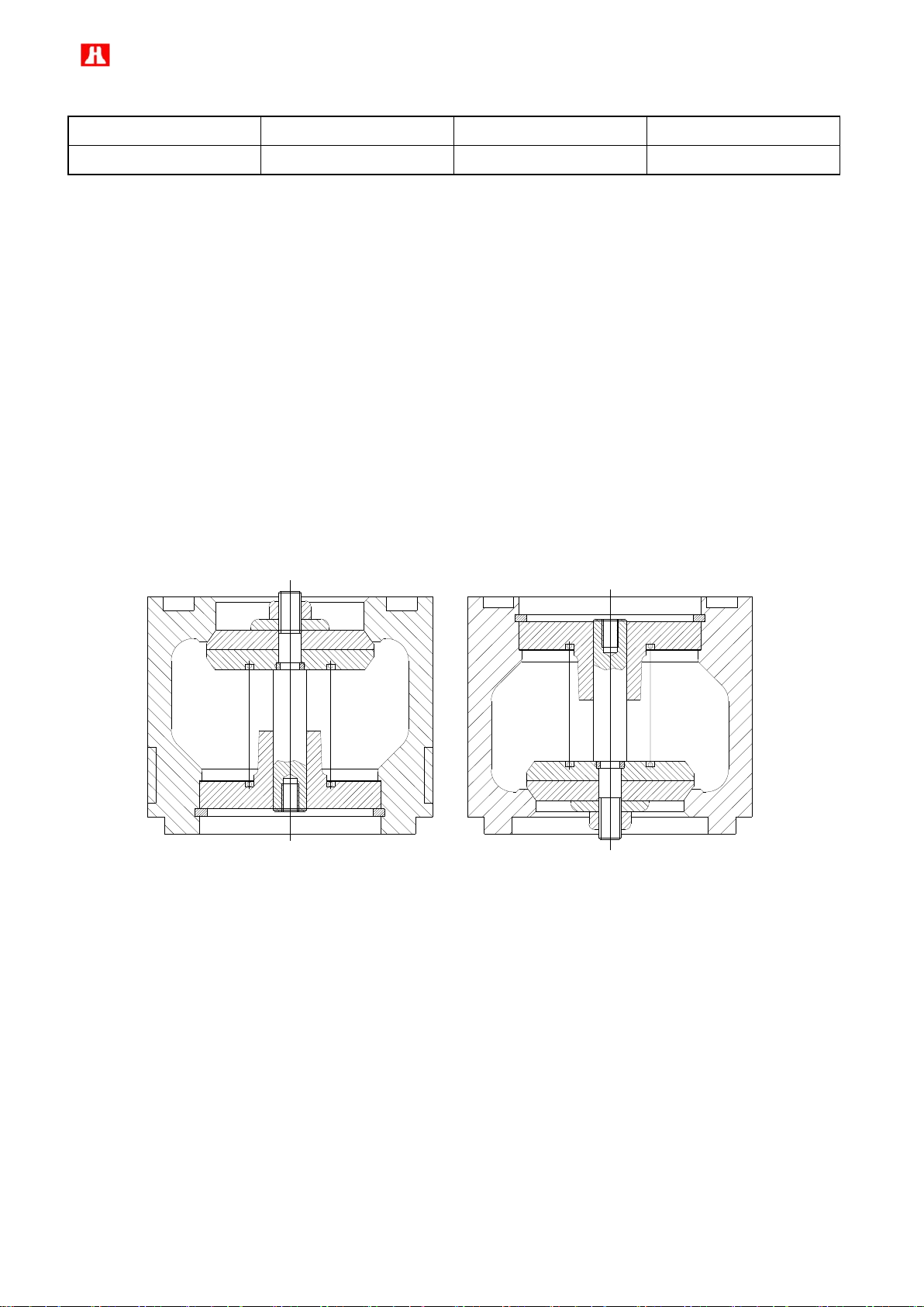
76
Maximum working pressure
Hydrostatic pressure test
Refrigerant
Temperature range
28 kg / cm² G
42 kg / cm² G
HFC, HCFC
40˚C~150˚C
Suction check valve Discharge check valve
* Specification of stop valve
c. Suction and discharge check valve
Hanbell designs a complete series of suction and discharge check valves for customer’s application. Suction
check valves are widely used in the refrigeration system (SST< -10℃) or system which has big pressure
differential between suction and discharge side. With the help of suction check valve, it can help to reduce the
reversal run time after compressors stop to protect bearings. For a parallel system, a discharge check valve on
the oil separator outlet is necessary. With an additional suction check valve installed on each compressor, it can
help to separate the suction pressure from discharge pressure if a common oil separator is used in the system.
Besides, suction check valve can prevent the unwanted refrigerant enters the suction port of non working
compressor because of head of height (potential energy).
The inner structure of suction check valve is opposite to the inner structure of discharge check valve which you
can see from the figures below. Users can contact Hanbell representative to get more information on the suction
and discharge check valves.
d. Oil temperature sensor
Oil temperature sensor is used to detect the oil temperature and control the oil heater. When oil temperature
reaches the setting value, oil heater will be off to save the energy. The oil heater and temperature sensor operate
with each other regardless whether the compressor is operating or not. Hanbell recommends keeping oil
temperature above 30 ℃ for a safe and easy start-up.
e. Oil level switch
Hanbell recommends installing an oil level switch on the external oil separator to ensure oil supply to the
compressor. To prevent from oil level switch trip caused by oil foaming or surging in the sump, a time delay
around 15 ~ 30 seconds is recommended before shut down the compressor.
Page 78

77
Max. contact capacity= 50VA DC/AC
*Flow Rate: max 50 (l/m)
*Weight:1.4KG/Set
*Working Pressure: 40 bar
(the weight is not including element)
*Material: Aluminum alloy
*Operating Temp.: from -25℃to 110℃
*Seal: VITON
Compressor Model
Material Code
Inlet Size
Outlet Size
RC2-100/140/180/200
230/260/300/310/320/340
/410/430/470/510
3130-3240AA
5/8”
5/8”
RC2-550/580/620/710/790
/830/930/1020/1130/1270/
1530
3131-3240AA
3/4”
3/4”
3130-3240AA
3131-3240AA
Initial contact resistance=150mΩ(Max.)
Switching voltage = 600V DC
Max. voltage = 300V DC/AC
Max. current = 0.5A DC/AC
Oil level switch on an external oil separator
f. External oil filter
External oil filter is optional accessory of external oil separator. It is suggested to install external oil filter in oil
return line before suction port of compressor for safe running of compressor.
External oil filter
Page 79
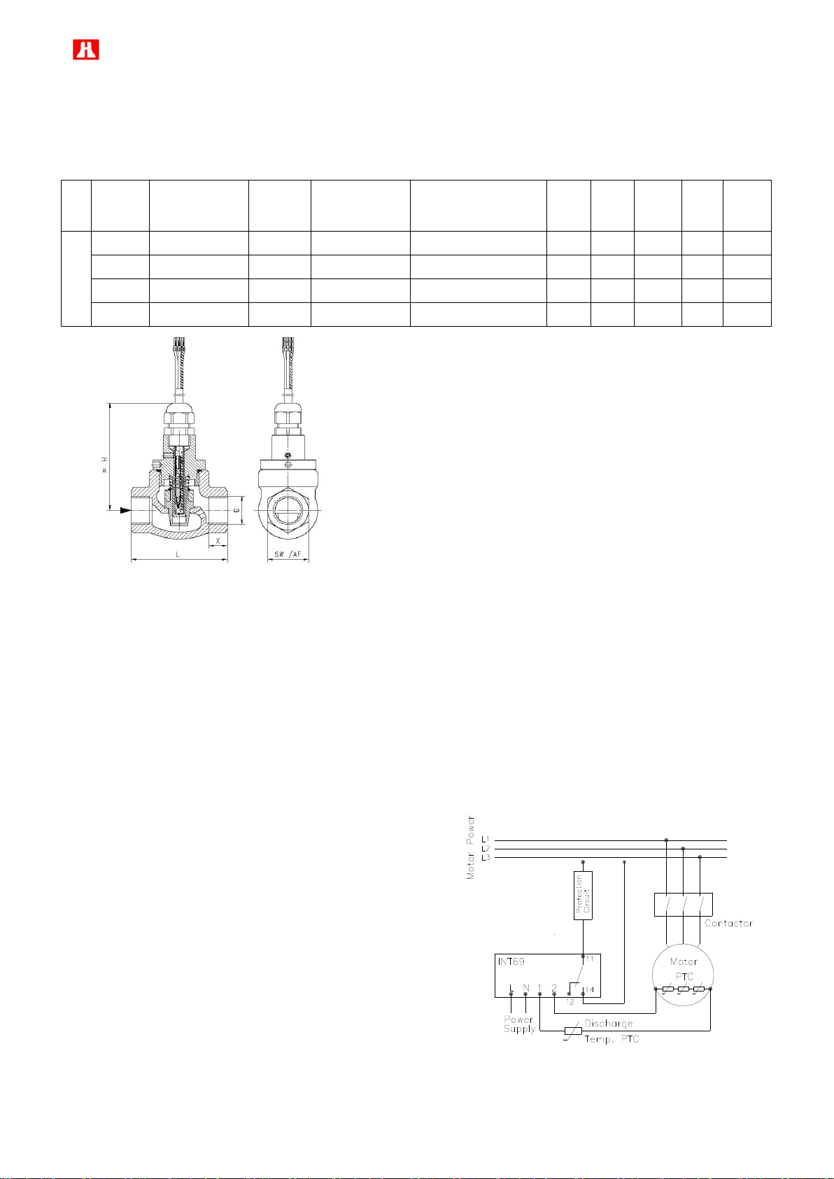
78
G
Type
PN
bar
Qmax. Recom.
l/min
switch value l/min
selectable range for
fixed switch
L
mm
H
mm
SW
mm
X
mm
Weight
kg
bronze
G 3/8
FF-010GR010
200
15
0.4-10
68
79
29
12
0.6
G 1/2
FF-015GR012
200
20
0.4-12
68
79
29
13
0.6
G 3/4
FF-020GR025
25
40
0.6-25
73
79
32
11
0.7
G 1
FF-025GR040
25
60
1.5-40
87
90
41
14
1
(1)Tolerance: ±0.3l/min
(2)Media temperature: max 110 ℃
(3)Average pressure loss: 0.4 bar at Qmax
(4)Hysteresis:depending on switch value minimum 0.4 l/min
Note: Switch value is indicated for horizontally decreasing flow
g. Oil flow switch
Oil flow switch is widely used on external oil circuit. With the installation of oil flow switch, user can ensure
sufficient flow rate of lubricating oil. Specifications are shown below.
Specification:
Outline drawing
h. INT69 control module and PTC temperature sensor
In order to protect compressor, each RC2 series compressor has been installed three PTC temperature sensors
inside motor coil and another one at the discharge side of compressor. These sensors are connected to an INT69
control module to monitor the motor coil temperature and discharge temperature as well. If the temperature in one
of the positions monitored exceeds the nominal response temperature of the respective PTC thermistor, the
sensor resistance increases and the INT69 control module output relay trips. The module resets when the
temperature drops below the response temperature by approx. 5K. The output replay provides a potential-free
change-over contact and is energized as long as the nominal response temperature is not exceeded.
Technical data of INT69
● Supply voltage
220V ~ 240V ±10%, 3VA , 40 ~60 Hz
115V -15% ~ +10%, 3VA , 50/60 Hz
● Ambient temperature
-30 ~ +70 ℃
● Relay output
Switch voltage AC 250V
Continuous current max. 6A
Page 80

79
i. INT69Y motor protector
V/2
W/3
U/1
X/8
Y/9
Z/7
A
B
B Set:PT100Ω/PT100Ω(Optional)
A Set:PTC
In addition to the temperature monitoring function of INT69, Hanbell also supplies INT69Y motor protector with the
monitoring functions of phase loss, phase sequence, motor temperature, discharge temperature as an optional
accessory.
INT69Y connection diagram PT100Ω/PT1000Ωconnection diagram
Note:Electric plate with PT100Ω/PT1000Ω connection (B) shown in above diagram is optional accessory. Only
when customer chooses PT100Ω/PT1000Ω function, Hanbell will supply this type of electric plate.
Phase loss, phase sequence:
Phase sequence and phase loss monitoring functions are active during a 5s window 1s after compressor start
( power on L1-L2-L3). If one of these parameter is incorrect, the relay locks out ( contacts M1-M2 are open). The
lockout can be cancelled by mains reset of approx. 5s (disconnect L-N)
Note: To make sure phase loss and phase sequence protection function well, please connect L1, L2 and L3 to
motor side as figure shown above.
Motor temperature:
Motor temperature is constantly measured by a thermistor (PTC) loop connected on S1-S2. If any thermistor
exceeds its response temperature, its resistance increases above trip level and the output relay trips ( contacts
M1-M2 are open ). After cooling down below the response temperature, a 5min time delay is activated. After the
delay has elapsed, the relay pulls in again (The contact M1-M2 is closed). The time delay can be cancelled by
mains reset of approx. 5s (Disconnect L-N)
Note: When choosing aforementioned INT69 or INT69Y motor protection, Hanbell strongly recommends adding
“Shutdown Lock-out” function and restarting by manual reset after abnormal trip and troubleshooting to prevent
too frequent cycle of “abnormal trip → auto reset → restart.”
Technical data of INT69Y
● Supply voltage ● Relay output
115V ~ 240V -15% ~ +10% 3VA , 50/60 Hz Switch voltage AC 240V, max. 2.5A, C300
Page 81

80
V/2
W/3
U/1
X/8
Y/9
Z/7
A
B
V/2
W/3
U/1
X/8
Y/9
Z/7
A
B
B Set:Pt100Ω/Pt1000Ω(Optional)
A Set:PTC
● Ambient temperature ● Phase sensor
-30 ~ +60 ℃ 3 AC, 50/60Hz, 200 ~ 575 V ± 10%
j. INT69HBY motor protector
Hanbell develops an optional accessory, INT69HBY motor protector, of which major functions are the same with
those of INT69Y: monitoring of phase loss, phase sequence, motor temperature, discharge temperature but with
manually reset function.
INT69HBY & PTC temperature sensors connection diagram
Other major functional descriptions are as follow:
1. When supply voltage is applied, the output relay pulls in after an initialization period of approx. 3 seconds,
provided all thermistors lie below their rated response temperature.
2. 1 to 9 PTC thermistors with varied rated response temperatures can be connected in series to the input
terminals.
3. If any thermistor resistance increases above trip level the relay drops out. This failure results in a lockout. (5
minutes delay for 1st PTC failure, 60 minutes delay for 2nd failure, lockout for 3rd failure.)
4. If a rapid temperature increase is detected (locked rotor condition), the output relay drops out. This failure results
in a lockout.
5. The phase monitoring function is active 1 second after motor start during a 10 second window. Incorrect phase
sequence results in lockout trip. Phase loss results in lockout trip.
6. Lockout and time delay can be cancelled by mains reset of approx. 5 seconds.
7. To avoid nuisance tripping due to reverse running after shutdown (pressure equalization), the phase monitoring
function is only re-enabled approx. 20 seconds after motor stop.
8. A twin LED (red / green) provides operational information.
9. The relay is fed out as a N/O dry contact, which is closed under good conditions.
10. Sensor and supply circuits are galvanic isolated.
11.The motor protector is not suitable for use with frequency converters.
Technical data of INT69HBY
●Supply voltage ●Relay output
Page 82
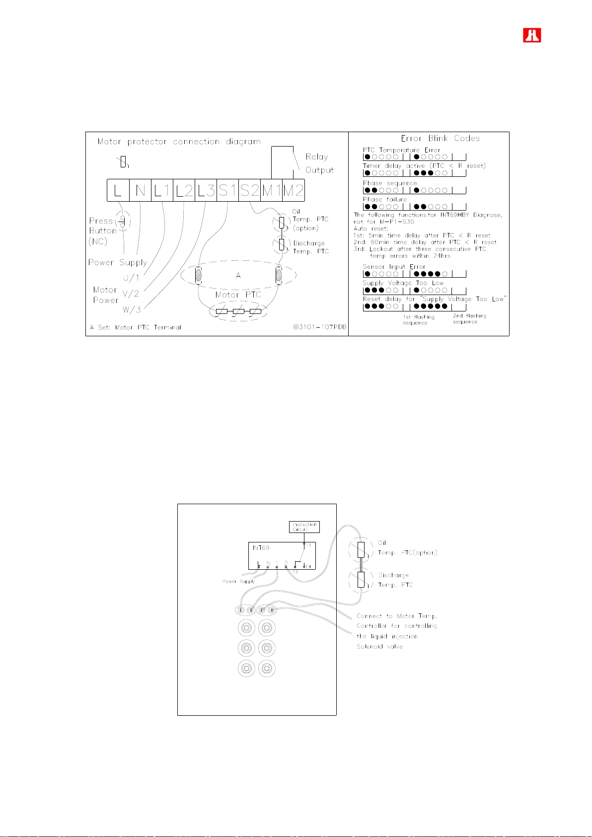
81
AC 50/60 Hz 115/120V-15 …+10% 3VA max. AC 240V, max. 2.5A, C300
indicates PTC sensor exceeds
its response temperature
V/2
W/3
U/1
X/8
Y/9
Z/7
A
B
B Set:Pt100Ω/Pt1000Ω(Option)
A Set:PTC
AC 50/60 Hz 230/240V-15…+10% 3VA min. > 24V AC/DC, >20 mA
●Ambient temperature ●Phase monitor
-30 … +70 ℃ 3 AC, 50/60Hz, 200 ~ 575 V ± 10%
k. Temperature sensors Pt100Ω or Pt1000Ω
PT100 or PT1000 is a kind of “built-in” type temperature sensor installed in the motor coil. Please connect it to
microcontroller of system and use for motor temperature display, setpoint of alarm & trip (lockout), and precisely
controlling liquid injection solenoid valve in order to properly protect Hanbell compressor.
LA-1090,1280 & 1520 compressor adopts independent liquid injection cooling system to motor. Other models
utilize suction return gas to cool motor coil. To effectively detect temperature of motor coil and adequately adjust
volume of liquid injection by measured temperature, Hanbell specially mounts PT100 or PT1000 sensor on motor
coil as an standard accessory for LA-1090,1280 & 1520 and optional accessory for others.
Page 83

82
Model
Type
Oil Volume (Liter)
Range of application based on
Displacement (m3/hr)
(Recommended)
Shell
Diameter
High level
Low level
OS40
Vertical
17
9
205
14”
OS50
Vertical
22
12
206~270
16”
OS65
Vertical
31
18
271~440
18”
OS80
Horizontal
33
20
441~705
20”
OS100
Horizontal
40
27
706~1120
20”
OS125
Horizontal
50
30
1121~1310
24”
OS150
Horizontal
60
36
1311~1835
24”
Recommended max. meas. Current for heat
coefficient <0.1K - DC 1 ~ 3 mA
Heating coefficient - 10mΩ/K
Sensor resistance at 0℃ - 100Ω±0.12Ω
Change of resistance 0 ~ 100℃ - 0.385Ω/K
Insulation test voltage U is – AC 1.5kV
Recommended max. meas. Current for heat
coefficient < 0.1K – DC0.2 ~ 2mA
Sensor resistance at 0℃ - 1000Ω±1.20Ω
Change of resistance 0 ~ 100℃ - 3.85Ω /K
Insulation test voltage U is – AC 1.5kV
Specification :
PT100 sensor
PT1000 sensor
l. External oil separator
Hanbell specially designs a complete series of external oil separators – OS series with characteristics of high
filtration efficiency and low pressure drop. The following table shows details of OS series:
Note : It is recommended to install a buffer before the external oil separator to avoid noise and vibration which
caused by resonance.
1. Technical data:
Page 84

83
2. Accessories:
No.
Description
OS40
OS50
OS65
OS80
OS100
OS125
OS150 1 Refrigerant inlet
1 1/2”
2”
2 1/2”
3”
4”
5”
6” 2 Refrigerant outlet
1 1/2”
2”
2 1/2”
3”
4”
5”
6”
3
Oil outlet
5/8” Flare
5/8” Flare
5/8” Flare
1” PF
1” PF
1 1/4”
PF
1 1/4”
PF
4
Oil charge valve
1/4” Flare
5
High oil S.G.
1 PCS
6
Low oil S.G.
1 PCS
7
Oil level switch
1 PCS
8
Oil heater
150W
150W
150W
150W
150W
300W
300W 9 Oil drain valve
1/4” Flare
10
Oil temp. protection
(option)
1/8” NPTF
11
Safety valve (option)
1/2”
1/2”
1/2”
1”
1”
1 1/2”
1 1/2”
No.
OS40
OS50
OS65
OS80
OS100
OS125
OS150
A
930
1050
1110
1227
1637
1829
2229
B
505
585
595
650
1000
1080
1480
C
240
275
300
568
354
409
409 D 300
350
350
300
300
400
400 E 18
22
22
23
23
23
23 F 320
360
360
688
698
830
830
3. Dimensions:
Vertical External Oil Separator-OS40, OS50, OS65
Page 85
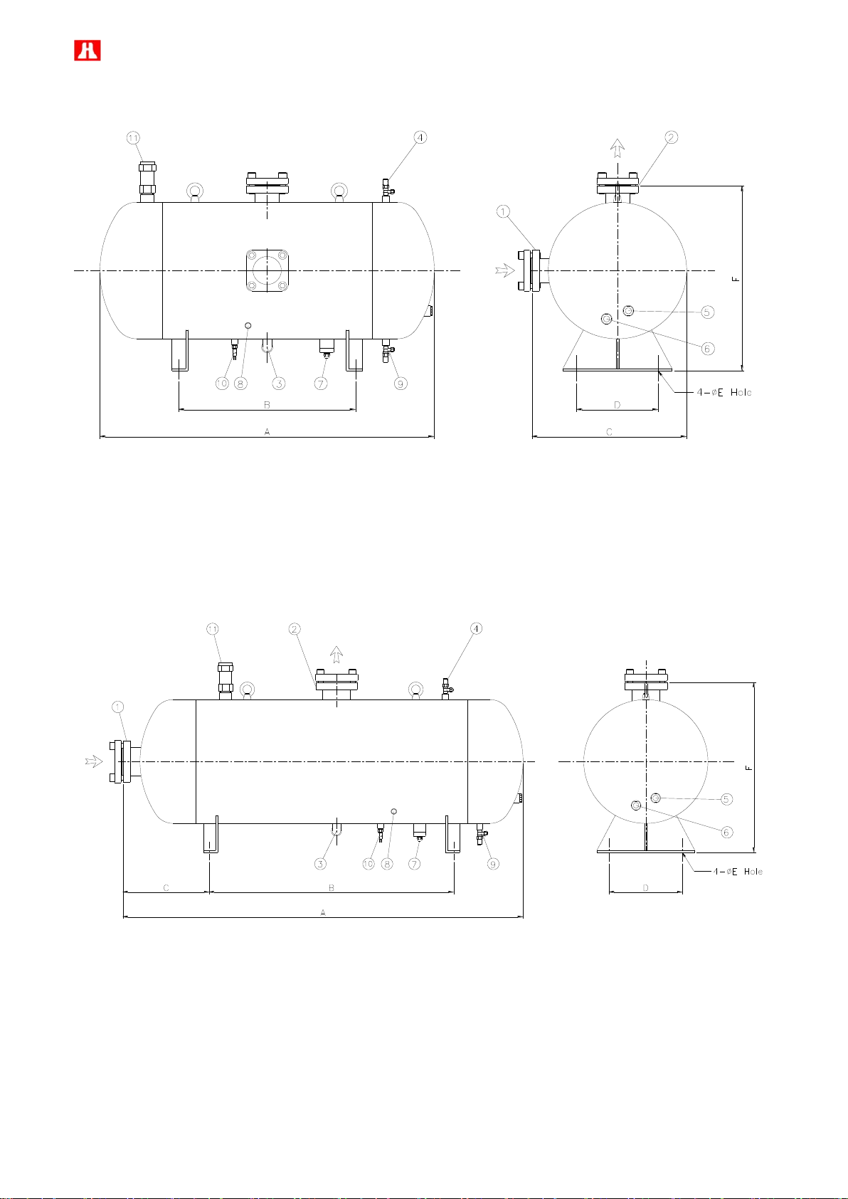
84
Horizontal External Oil Separator-OS80
Horizontal External Oil Separator-OS100, OS125, OS150
Page 86
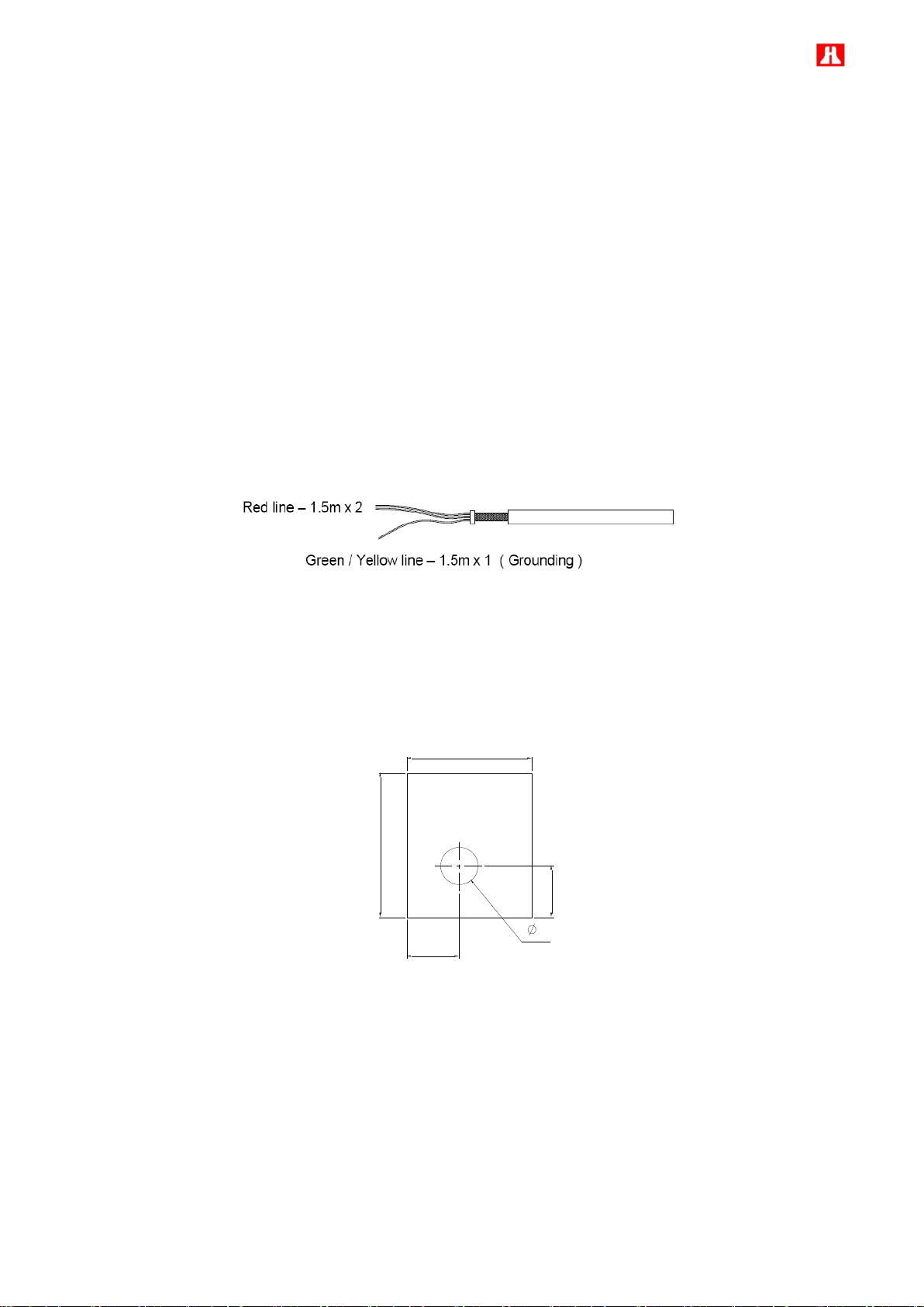
85
m. Oil heater
A
E
B
C
D
Oil heater is used to maintain the oil temperature in the oil separator during shutdown cycles. It can help to get a
safe start-up especially when the ambient temperature is low. Oil heater should be energized only when the
compressor unit is not in operation and should not be energized when there is no oil in the reservoir. The selection
of oil heater depends on total quantity of oil.
Before restart of compressor after shutdown for a long time, please turn on oil heater at least 8 hours to make the
temperature inside compressor higher than system temperature and ambient temperature and then it can prevent
condensation of refrigerant inside oil sump of compressor which may result in liquid compression in next start and
poor lubrication due to too low viscosity. In addition, Hanbell also offers 300W oil heater to keep adequate
lubricant temperature for large external oil separator and applications in areas with low ambient temperature.
Specification : 150W, 300W, 110V or 220V, IP 54, UL approval
150W , 300W oil heater
n. Mounting pad
To avoid extra vibration and noise resulted from direct contact between compressor footings and the base on
which compressor is mounted, it is recommended to add mounting pads in between as the drawing below shown.
Page 87

86
Model
A B C D E
Thickness
RC2-100F
RC2-140F
RC2-180F
RC2-200F
RC2-230F
RC2-260F
RC2-300F
RC2-310F
25
70
60
25
18
15 mm
RC2-340F
RC2-370F
RC2-410F
RC2-430F
RC2-470F
RC2-510F
RC2-550F
RC2-580F
RC2-620F
RC2-710F
RC2-790F
RC2-830F
RC2-930F
35
110
85
30
22
15 mm
RC2-1020F
RC2-1130F
RC2-1270F
RC2-1530F
42.5
105
85
41
22
15 mm
Page 88

87
7. Operation and trouble shooting
Items
Things to be checked
States or standard values
1. Accessories
1. Oil level
2. Oil heater
3. System valves status
4. Solenoid valves
5. Capillary
1. Higher than the middle line of oil level sight glass
2. Should be kept energizing after compressor shut
down.
3. Opened
4. Fixed
5. No serious distortion or damaged
2. Electrical system
1. Voltage of main power
2. Voltage of control circuit
3. Insulation resistance value of the
motor between phase to phase and
phase to ground.
4.
terminal connection.
5. Grounded
6. Capacity of electrical accessories
7. Settings of switches, sensors and
controllers.
Electricity voltage should be kept within 5 to
the rated voltage, instant maximum voltage drop
while starting should be less than 10% to the
rated voltage.
If there is other demand, contact HANBELL.
3. Insulation resistance value should be above
5M.
4. Power terminals are firmly fixed on terminal block
and well insulated. Keep wire cables away from
heat source and sharpened metal. Power
terminals are fixed firmly and well insulated.
Terminal screw and block are both required.
5. (Ruled by the local Electricity Regulations.)
6.
designer.)
7.
designer.)
3. Piping system
1. Outer piping system
2. Leakage test
3. Bolts to fix the compressor.
1. Fixed firmly.
2. No leakage.
3. Fix the compressor tightly.
4. Safety devices
1. Motor coil sensor (thermister)
2. Discharge sensor (thermister)
3. Controller
1. Connected in series with discharge sensor to
controller.
2. Connected in series with motor sensor to
controller.
3. Closed circuit with N.C. & N.O.
7.1 Compressor start-up
PRE-START CHECKING Table below shows the required procedures and checkpoints before starting-up the
compressor during commissioning or initial operation of the unit.
Note:
1. Don’t start compressor under vacuum.
2. Check the rotating direction of screw compressor by checking its suction and discharge pressure. The correct
rotating direction is: suction pressure drops immediately and the discharge pressure increases at the same
time.
3. It is necessary to pay more attention to the auxiliary facilities while the chiller is commissioning at the job-site
and the periodic maintenance after the initial start-up.
4. Danger or severe damage to compressor is possible if the compressor is flooded with oil during standstill.
5. Check that all the settings on each pressure switch are correct.
6. Oil foaming can be generated during starting phase, but it should reduce when the compressor is under stable
Page 89

88
operating conditions. Otherwise this can indicate excessive liquid in the suction gas.
7. Avoid touching the compressor surface during compressor operation.
8. Don’t remove any parts of compressor before release the compressor inner pressure.
9. The discharge temperature of compressor is recommended to be controlled at 80 ℃ for R22 and HFC
application. Normally the discharge temperature doesn’t increase quickly after starting. If it increases quickly
during commissioning, user should review the oil supply situation and additional cooling status.
10. The supply oil temperature should be kept below 60 ℃ for R22 and HFC application.
11. The oil level in oil separator might slightly drop after the start-up. A lower level happened by gas or air spot
which is existed in oil circuit. If the level continuously goes down, an oil separator problem should be assumed.
User should check the working condition and find out the problem during the commissioning.
12. During the commissioning, user should listen if any abnormal noise comes from compressor’s bearing seat or
compression casing. Normally a middle tone of rhythmical sound can be obtained. Irregular, high tone and
metallic noise show some abnormal conditions that the compressor is passing through. User should stop the
compressor immediately and find out the root cause of abnormal noise.
13. Vibration shall be checked carefully by using a vibration analyzer on compressor casing, the surface of the
base frame and piping. Compressor itself doesn’t generate excessive vibration if mechanical condition and
shaft alignment are normal. Therefore, resonance should be often the cause of vibrations.
14. Normally the pressure drop at oil filter should be around 0 to 0.5 bar. If the pressure drop is continues rising
and reaches 1 bar. The oil filter cartridge should be cleaned or replaced to ensure a sufficient oil supply.
15. Normally the pressure drop at suction strainer is around 0 to 0.2 bar. If the pressure drop is continues rising
and reaches 0.5 bar. The suction strainer should be cleaned or replaced immediately.
16. Check sight glass on liquid line to see the supply condition of refrigerant.
17. Check suction gas superheat not only at 100% capacity, but also 75%, 50% and 25% capacity to ensure
sufficient superheat for system operation.
18. Avoid slugging compressor with liquid refrigerant. Make certain that adequate superheat or properly size
suction accumulator is applied to avoid dumping liquid refrigerant into compressor. Keeping liquid injection
valves properly adjusted and in good condition to avoid flooding compressor with liquid.
19. The whole plant, especially the pipelines and capillary tubes must be checked for abnormal vibrations.
Contact HANBELL or local distributor if any abnormal vibrations or noise found while the compressor is
running.
20. The running condition of compressor after commissioning at the job-site should be adjusted as; the discharge
temperature will be at least 20K above the saturated condensing temperature and the suction vapor
superheat should be within 10K to the saturated evaporating temperature.
21. Regularly check-up the plant according to national regulations and the following items should also be
checked:
- Operating data of the machine
- Check the lubrication/level of oil
- All compressor monitoring parts
- Check electrical cable connections and tightness
Page 90

89
7.2 System adjustment
This session is mainly focused on system adjusting besides compressor. The information here is based on
general type or common situation. Any special design or different case should be reviewed separately with
Hanbell representative
Liquid/Oil injection to chamber
Liquid/Oil injection to chamber is widely used for the controlling of discharge temperature. In the case of using
Liquid/Oil injection to chamber for the discharge temperature control, the Liquid/Oil line should be controlled by a
liquid line solenoid (Normally Closed type). The liquid line solenoid is suggested to be energized when the
discharge temperature reaches 80 ℃ (HFC and HFC application). On the Liquid/Oil line, there should be a
regulation valve after the solenoid to adjust the injection flow rate. Before the start-up of compressor, user should
completely close the regulation valve. When the system is running and the discharge temperature exceeds the
set-point, the N.C. solenoid will be energized and user can open the regulation valve gradually to see the variation
of discharge temperature. Try to adjust the regulation valve to the position that the discharge temperature starts to
decrease to the setting point then keep the valve at this position for a while. When the discharge temperature
down to 75 ℃ (HFC and HFC application), the liquid line solenoid can be off to stop the injection. Normally the
discharge temperature will start to increase after the stop of Liquid/Oil injection. Therefore, user should observe
the working situation for some time to ensure the proper work of Liquid/Oil injection.
Note: The adjustment of Liquid/Oil injection regulation valve should be executed at all operating conditions,
including partial load.
ECO function
ECO is often used in the refrigeration system to get higher cooling capacity. Compared with using 2 compressors
at a 2-stage compression system, using ECO can save the initial investment and simplify the system design. The
information below should be noted when user applies ECO in the system.
1. There should be a muffler connected to the ECO port directly to absorb the pulsation caused by high speed
refrigerant/gas flow. Sight glass is recommended to be used on the ECO pipe to know whether liquid exists or
not. If liquid refrigerant enters the compression chamber, this will cause damage to screw rotors and bearings.
Accumulator can be used in this line to avoid liquid compression.
2. In a regular start procedure with ECO application, ECO line solenoid (Normal Close Type) should be
energized after the slide valve reaches its minimum ECO working position and should be energized all the
time during the compressor working period. Running compressor without sufficient cooling might cause
severe damage to compressor.
3. Before stop the compressor, the controlling program should unload the slide valve to its initial position
(minimum capacity). ECO line solenoid should be off when the slide valve position is below minimum ECO
working position.
Page 91

90
2
/cmkg
2
/cmkg
Discharge bypass line
Discharge bypass line is widely used to reduce the pressure differential between low and high pressure side. In
this kind of application, the discharge check valve is normally installed on the oil separator outlet which can isolate
the high pressure side (condenser) from the oil separator side. Because a suction check valve is usually installed
on the compressor’s suction port, the pressure in oil separator and compressor will be equalized in the end. Using
a discharge by pass line which connects the oil separator and the suction pipe line can reduce the pressure in the
oil separator to ensure a light-duty-start of the compressor.
Oil cooler
Oil cooler is often used to control the oil temperature at desire setting. The proper oil temperature can ensure the
oil viscosity and lubricity and can provide necessary help for chamber cooling and discharge temperature control.
Because the oil temperature in the beginning of system running is not high (normally around 20 to 30 ℃), oil
cooling will not be necessary during this period. By pass the oil at oil cooler can help to increase the oil
temperature faster to the desired temperature and having system stabilized. When the oil temperature reaches
the setting, oil cooler can start to work to control the oil temperature for the system.
Oil cooler should be installed as close as possible to the compressor and preferably below the level of compressor
/ oil separator to avoid gas pads or any drainage of oil into the oil separator during standstill.
Oil filter
Oil filter is usually installed on the oil line. User should consider installing a pressure differential protector which
helps to monitor the pressure drop between both sides of oil filter. When oil pressure drop reaches 1 to
1.2
supply to compressor. Insufficient oil supply leads to severe damage to internal moving parts and malfunction of
capacity control.
Oil pump
When pressure differential between main oil inlet port and suction side is less than 4
oil pump for the oil circuit becomes important. The oil pump should start and stop simultaneously with the
compressor to ensure sufficient oil supply.
Oil return valve (for fine/secondary oil separator)
, this means the oil filter is clogged by debris or dirt and user should clean it to ensure sufficient oil
, it means using an
In the case of using fine/secondary oil separator, an oil return line from the bottom of fine/secondary oil separator
to compressor’s suction side is very important. The control of oil return valve can be simply by a solenoid valve
with a regulation valve or using a floating ball as a trigger and be opened only after the compressor starts. User
should adjust the flow volume during the initial start up to ensure a steady oil return to the system.
Pressure regulation valve
Pressure regulation valve is suggested to be installed on the exit of the external oil separator when oil pump is not
applied in the system. With its help, the oil pressure can be built up quickly to ensure sufficient oil supply to
Page 92

91
compressor. User should use suction pressure as reference and make sure the valve opened when the discharge
2
/cmkg
pressure is 4
temperature condition.
7.3 Compressor stop
Compressor stop should be executed under regular procedure. The controlling program should unload the
compressor gradually to its minimum capacity and stop the compressor after it reaches the minimum load. Oil line
solenoid and oil pump (if apply) should be closed at the same time when the compressor stops. ECO line should
be closed when the slide valve position is below 50%. Oil/Liquid injection line should be closed 3 to 5 seconds
before the compressor stop. For the first start-up, check and clean the suction strainer and oil filter after the
commissioning is very important to ensure the future operation.
In case of emergency stop, the oil/liquid injection line, oil line, and ECO line should be closed immediately. If
discharge bypass line is designed in the system, it should be opened to balance the pressure differential between
high and low pressure side then close itself for the next running. With the help of suction check valve and
discharge bypass line, the reverse running time can be limited to a few seconds. If the reverse running doesn’t
stop in about 10 seconds, the leakage at suction check valve and the malfunction of discharge bypass line can be
assumed, User should check them during the stop of compressor. Before starting the compressor next time, user
higher than the suction pressure. This is essential especially in the low condensing
should correct the problem first then energize all solenoid valves to help the slide valve back to its initial position.
For a short period of non-operation, the oil heater power should be kept on to keep the oil temperature at proper
temperature for the next start up.
For a long period of non-operation or overhauls, the power source for main and oil pump should be cut off. The oil
heater power should be switched off, too. The control panel should be kept power on to resist moisture. All the
stop valves related to the system should be closed. Cooling water supply should be stopped and the cooling water
in the condenser and oil cooler must de drained completely.
Note: Start and stop of compressor should not be repeated more than 4 times per hour.
Page 93

92
PROBLEMS
PROBABILITY CAUSES
REMEDY / CORRECTIVE ACTION
Sudden trip of motor
thermister / sensor
Low suction pressure cause low refrigerant flow rate
Install liquid injection to motor coil
Refrigerant shortage
Charge refrigerant
Suction filter clogged
Clean filter
High suction temperature
Install liquid injection to motor coil
High suction superheat
Adjust the superheat less than 10°K
Unstable electricity system or failure
Check electricity power supply
Motor overload
Bad motor coil causing temperature rising rapidly
Compressor unable
to load
Low ambient temperature or high oil viscosity.
Turn on the oil heater before compressor start.
Capillary clogged.
Clean or replace capillary
Modulation solenoid valve clogged or solenoid valve coil burnt.
Clean / purge solenoid valve core or replace the
solenoid valve coil
Internal built-in oil line clogged.
Check and clean the compressor oil circuit
Piston stuck-up.
Change piston or piston ring
Oil filter cartridge clogged.
Clean oil filter (replace if needed)
Too small the high-low pressure differential.
Minimum pressure differential is 4 bar. Consider to
install an oil pump.
Compressor unable
to unload.
Modulation solenoid valve clogged or burnt.
Clean or replace the solenoid valve
Piston rings worn off or broken, or cylinder damaged resulting leakage.
Change piston (if cylinder damaged severely, change
the cylinder)
Lubrication oil insufficient
Check the oil level of the compressor if enough, add
some oil if necessary
Leakages at internal discharge cover plate end side.
Check or replace the gasket and tighten the bolts.
Solenoid valve voltage misused.
Check the control voltage
Piston stuck-up.
Change the piston set, and check the cylinder and slide
valve.
Capacity control logic unsuitable.
Check
Poor insulation of
motor
1. Bad compressor motor coil.
Check the coil or change the motor stator
2. Motor power terminal or bolt wet or frosty.
3. Motor power terminal or bolt bad or dusty.
4. Bad insulation of magnetic contactors.
5. Acidified internal refrigeration system.
6. Motor coil running long time continuously under high temperature.
7. Compressor restart counts too many times.
7.4 Troubleshooting
The table below shows some problem that might encounter in the jobsite during commissioning or upon operation
of compressor. This table will only serve as a guide for the Engineer to understand the situation once the problem
occurred in the site.
Page 94

93
PROBLEMS
PROBABILITY CAUSES
REMEDY / CORRECTIVE ACTION
Compressor starting
failure or Y-Δ starter
shifting failure
Slide valve piston unable to go back to its lowest % original position.
Check if the unloading SV is energized once the
compressor shut down.
Unload the compressor before shot down.
Voltage incorrect.
Check the power supply
Voltage drop too big when starting the compressor or magnetic
contactor failure or phase failure.
Check the power supply and the contactor.
Motor broken down
Change the motor
Motor thermister sensor trip.
See “sudden trip of motor sensor” above
Incorrect supply power connection.
Check and re-connect
Y-Δ timer failure.
Check or replace.
Discharge or suction stop valve closed.
Open the stop valve
Improper connection between node terminals of Y-Δ wiring.
Check and re-connect the wiring
Rotor locked
Check and repair
Earth fault
Check and repair
Protection device trip
Check
Abnormal vibration
and noise of
compressor
Damaged bearings.
Change bearing.
Phenomenon of liquid compression.
Adjust proper suction superheat
Friction between rotors or between rotor and compression chamber.
Change screw rotors or/and compression chamber.
Insufficient lubrication oil.
Check the oil level of the compressor if enough, add
some oil if necessary.
Loosen internal parts.
Dismantle the compressor and change the damaged
parts.
Electromagnetic sound of the solenoid valve.
Check
System harmonic vibration caused by improper piping system.
Check the system piping and if possible improve it
using copper pipe.
External debris fallen into the compressor.
Dismantle the compressor and check the extent of the
damage.
Friction between slide valve and rotors.
Dismantle the compressor and change the damaged
parts.
Motor rotor rotates imbalance.
Check and repair.
Compressor does not
run
Motor line open
Check
Tripped overload
Check the electrical connection
Screw rotors seized
Replace screw rotors, bearings etc….
Motor broken
Change motor.
High discharge
temperature
Insufficient refrigerant.
Check for leaks. Charge additional refrigerant and
adjust suction superheat less than 10°K
Condenser problem of bad heat exchange.
Check and clean condenser
Refrigerant overcharge.
Reduce the refrigerant charge
Air / moisture in the refrigerant system
Recover and purify refrigerant and vacuum system
Improper expansion valve.
Check and adjust proper suction super heat
Insufficient lubrication oil.
Check the oil level and add oil.
Damaged bearings.
Stop the compressor and change the bearings and
other damaged parts.
Improper Vi value.
Change the slide valve.
No system additional cooling (Liquid injection or oil cooler)
Install additional system cooling (liquid injection or oil
cooling or both base on working condition limitation)
Page 95

94
PROBLEMS
PROBABILITY CAUSES
REMEDY / CORRECTIVE ACTION
Compressor losses
oil
Lack of refrigerant
Check for leaks. Charge additional refrigerant.
Improper system piping
Check and correct the piping or install an external oil
separator
Refrigerant fills back
Maintain suitable suction superheat at compressor
Low suction pressure
Lack of refrigerant
Check for leaks. Charge additional refrigerant.
Evaporator dirty or iced
Defrost or clean coil
Clogged liquid line filter drier
Replace the cartridge
Clogged suction line or compressor suction strainer
Clean or change suction strainer
Expansion valve malfunctioning
Check and reset for proper superheat
Condensing temperature too low
Check means for regulating condensing temperature
Note: The replacement of compressor internal parts should be perform only by a qualified / certified service
technician with full knowledge of HANBELL screw compressor or it should be a Service Engineer from
HANBELL.
Page 96

95
7.5 Compressor checking list
Please fill out the compressor checking list and send it to Hanbell, if any failure of compressor happened. Hanbell
will reply and suggest the solution to resolve the failure.
Page 97
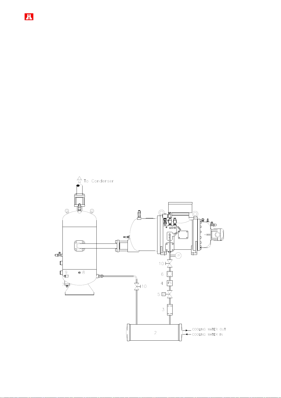
96
gcmkg2/
2
/cmkg
8. System applications
8.1 General application
Compressor is the heart of the chiller/refrigeration system. To ensure a long trouble free operation, the following
design factors need to be considered during the design stage for the system designer.
a. Oil circulation
Compare with traditional reciprocating compressor using oil pump for oil circulation, Hanbell screw compressor
uses pressure differential as the pushing force for oil circulation. To ensure the capacity control function and good
oil supply to compressor, minimum 4
is necessary. System designer should consider installing the necessary pressure sensors to get the pressure
values at main oil inlet port and suction side and use them as reference to monitor the oil supply condition.
For compressor working with R22 and HFC refrigerant, a general oil circulation diagram can be referred to the
picture below. The pressure drop at oil cooler and oil filter should be recorded as reference. Once the pressure
drop increases more than 1
good heat exchange at oil cooler and sufficient oil supply to compressor.
, regular maintenance on oil cooler and oil filter should be executed to ensure
pressure differential between main oil inlet port and suction side
Oil circulation design for R22 and HFC refrigerant
Page 98

97
2
/cmkg
If the oil pressure differential can’t reach 4
should be assigned to build up the necessary oil pressure for oil circulation. User can follow the figure below for
design reference. In the oil pump section, an oil filter can be found before the oil pump. It is installed to protect the
oil pump away from debris and piping dirt. A pressure regulator can be seen parallel to the oil pump line. It is used
to control the maximum oil pressure. The function of check valve is letting oil pass through it when the oil pressure
is enough. Under such condition the oil pump won’t need to work and oil can be supplied from the oil separator to
the compressor directly. The other function is to prevent back-flow of oil when oil pump works
between main oil inlet port and suction side, an oil pump
Oil pump application
When the evaporator is far away from the compressor, system designer should consider designing proper suction
line to help the oil flow back from the evaporator. From the outlet of the evaporator, the suction line should always
drop vertically downward or run horizontally at a downward slope (1 cm per m) to a point where it then drops
vertically downward. When the line comes to a risen part, a trapping technique similar to that for the discharge line
is used. Please refer to the figure below for details.
Suction line design for risen part
Page 99

98
For system with flooded evaporator at HFC and R22 application, a separate oil rectifier from the evaporator or the
low-pressure receiver is required. Basically the oil/refrigerant mixture should be drawn off at several points in the
oil-rich phase of the liquid level. Using means of heat exchange to evaporate the refrigerant fraction (e.g. in a
counter flow with the warm refrigerant liquid) then feed back the oil via the suction gas line. Checking the oil level
in the external oil separator is required to ensure sufficient miscibility (oil/ refrigerant) under the corresponding
operating conditions in the evaporator or oil separator. When the oil circulation problem cannot be solved, a
secondary oil separator is required to minimize the oil carryover to the system.
b. Piping arrangement
In the case of single compressor, the suction line design before compressor should have a sufficiently large
volume and should not be angled towards the compressor. Please refer to figure below for details.
In the case of parallel compounding, the suction line runs below the level of compressor is recommended to
provide the maximum possible safety. In system where liquid slugging cannot be avoided (e.g. system with long
standstill under a pressure difference, hot gas defrost), the suction header shall able to take over the function of a
liquid separator. Please refer to figures below for design reference.
Suction line design before compressor (single compressor)
Suction line design before compressors (parallel compounding)
Page 100

99
Suction line design before compressors (parallel compounding)
Suction line design from suction header to compressors (parallel compounding)
When suction header has to be positioned above compressor level, the following design reference has to be
considered for safety operation.
Design reference when suction header runs above the compressors
 Loading...