

Page 1
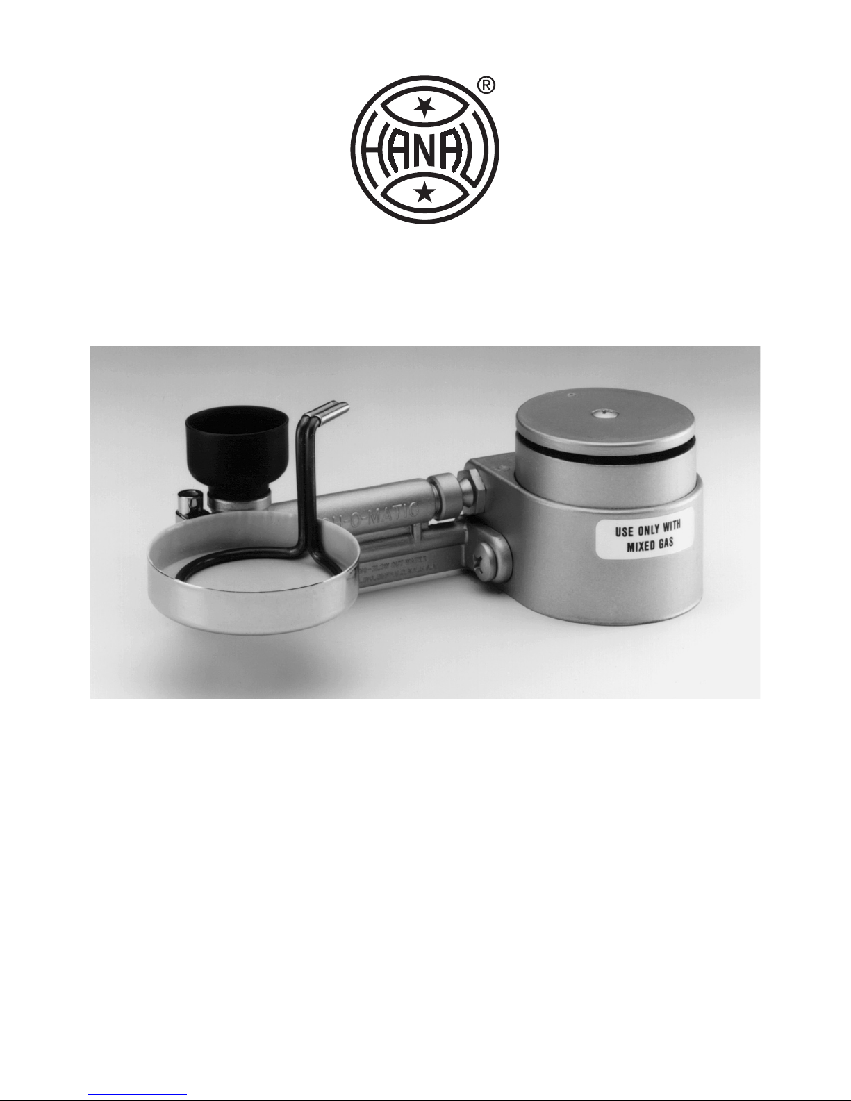
HANAU™ TOUCH-O-MATIC®
BUNSEN BURNER
Read all instructions before using the Touch-O-Matic®.
Save these instructions for future reference.
The Touch-O-Matic® bunsen burner is a gas burner. The burner
can operate on five types of gas: butane, propane, natural gas,
mixed gas or manufactured gas, depending on the nozzle installed
in the Touch-O-Matic® bunsen burner. The Touch-O-Matic® can be
used for a wide variety of lab applications. The pilot light makes it
convenient for intermittent use.
Page 2
Important Safety Information
Warning
DO NOT USE AROUND FLAMMABLE MATERIALS.
Misuse of the burner can cause an explosion or fire and
result in burns and property damage.
DO NOT USE FUEL OTHER THAN THE ONE SPECIFIED ON THE LABEL AND NOZZLE. Use with an
improper fuel may cause dangerous operation. See
the “Gas Conversion” section for operation with other
gases.
DO NOT USE THE BURNER WITH ACETYLENE.
CONNECT THE BURNER TO THE GAS SUPPLY WITH
A HOSE APPROVED FOR THE GAS USED AND A
SHUTOFF FOR THE GAS. Verify the ON-OFF Platform is in the intermittent (OFF)
position before turning on the gas supply to the burner.
USE A GAS PRESSURE REGULATOR WHEN USING THE BURNER FOR PROPANE OR BUTANE. Pressure regulators, not supplied with the burner, must be
connected between the gas supply and the burner. Without the regulator, the
flame size cannot be controlled.
DO NOT LEAVE THE BURNER ON WHILE IT IS UNATTENDED. This includes the
Pilot Light. If the Pilot Light or flame goes out, gas will accumulate and may create an explosion hazard.
KEEP ALERT FOR THE SMELL OF GAS WHEN THE BURNER IS USED. Do not
operate the burner if parts are missing or the unit has been damaged. If Touch-OMatic® is dropped, check it carefully for cracks or other damage. Be alert for any
improper operation. Return the unit to Whip Mix for examination and repair if any
problem is encountered.
DO NOT USE THE NEEDLE VALVE AS AN ON/OFF VALVE. Turn the burner off by
shutting off the gas supply valve. The Needle Valve does not control gas to the
Pilot Light.
DO NOT TAMPER WITH SCREWS (4) LOCATED INSIDE VALVE HOUSING.
IF PROPANE IS USED, DO NOT STORE PROPANE TANKS INDOORS.
WARNING
Page 3
Installation
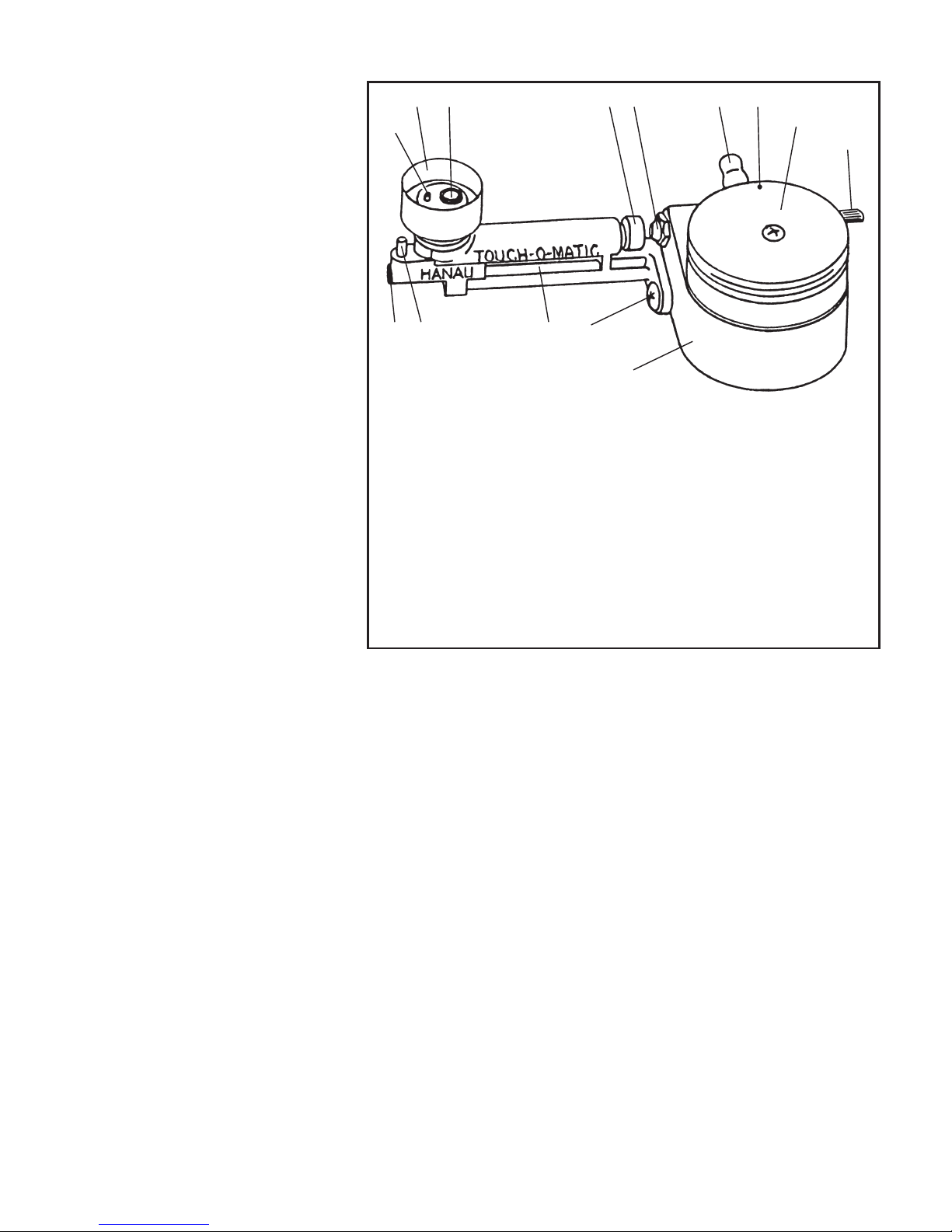
Securely attach an approved
gas hose (not supplied)
from the gas cock of your
fuel source to the Gas Hose
Intake Connector -. Slip
the Pilot Light Shield 1 on
to protect the Pilot Light
2
flame from accidentally
being blown out by air
movement.
Pilot Light
Adjustment
Turn on the gas supply and
light the Pilot Light 2 with
a match or lighter. NOTE:
When lighting the Pilot
Light, it may be necessary
to allow gas to flow for a
few seconds before ignition
occurs. Using a small slotted
screwdriver, turn the Pilot
Flame Adjustment Screw 4
to increase or decrease the height of the Pilot Light flame. Adjust the height of the
flame to be low, yet functional and not likely to be blown out. Unless the Pilot flame
is used for the optional Waxing Cup t and Loop Heat Conductor y (see Figure 3),
a 1/4” (6 mm) flame is typically used.
When using the Waxing Cup t, it may be necessary to set the Pilot Light 2 flame
higher to keep the wax in the wax cup soft or in a liquid state. See the Waxing Cup
and Loop Heat Conductor section for more information.
To Adjust The Air-Gas Mixture
Light the Pilot Light 2 as directed above, then depress the ON-OFF Platform 9
and turn the platform clockwise, or counterclockwise, slightly so it remains in the
down (ON) position. This permits the burner to operate with a continuous flame.
Adjust the volume of the gas and the height of the flame by opening or closing the
Gas Adjustment Thumbscrew 8. Turn the Air-Intake Adjustment q until a bright
blue flame with a blue inner cone is obtained. Readjust the fuel and air, if desired.
1 r q = - 0
9
8
2
4 3 5 6
7
Figure 1: Touch-O-Matic
®
1 Pilot Shield
2 Pilot Light
3 Post for Waxing Cup
4 Pilot Flame Adjustment
Screw
5 Burner Assembly
6 Screw for Detaching Burner
Assembly
7 Valve Housing
8 Gas Adjustment Thumbscrew
(needle valve)
9 ON-OFF Platform
10 Intermittent/Continuous
Flame Indicator
11 Gas Hose Intake Connector
12 Gas Nozzle
13 Air-Intake Adjustment
16 Burner Tube
Page 4
Operation
Turn on the gas and light the Pilot Light 2 and adjust the air-gas mixture as
directed above. Operate with an intermittent or continuous flame as directed below.
Intermittent Flame
Locate the small dot, Intermittent/Continuous Flame Indicator 0, on the ON-OFF
Platform 9. When this is aligned with the Gas Hose Intake Connector -, the
burner is ready for intermittent operation. Depressing the platform releases gas to
the main burner where it is ignited by the Pilot Light 2 flame. Removing pressure
from the platform shuts off the supply of gas to the main burner.
Continuous Flame
Depress the ON-OFF Platform 9 and turn it slightly clockwise, or counterclockwise, until it locks and remains in the down position. The flame will burn
continuously until the platform is returned to its original OFF (up or intermittent)
position with the Intermittent/Continuous Flame Indicator 0 oriented toward the
Gas Hose Intake Connector -. Turn the ON-OFF Platform back to the intermittent
(OFF) position before turning off the gas.
To remove wax drippings, remove the Screw for Detaching the Burner Assembly 6
from the Valve Housing 7. Detach the Burner Assembly 5 from the Valve Housing,
and place the Burner Assembly in boiling water. DO NOT place the Valve Housing in
water. The “O” Ring (14) does not have to be removed, but be careful not to lose it.
Use care to not bend the Pilot Inlet Tube.
Care and Cleaning
To remove wax
drippings, remove
the Screw for
Detaching the
Burner Assembly
6
from the Valve
Housing 7.
Detach the Burner
Assembly 5 from
the Valve Housing,
and place the
Burner Assembly
in boiling water.
DO NOT place
the Valve Housing
in water. The “O”
Ring w does not have to be removed, but be careful not to lose it. Use care to not
2
5
6
7
Figure 2: Disassembly for Cleaning
BOIL
r
q
=
e
w
Page 5
bend the Pilot Inlet Tube e. Before reattaching the Burner Assembly, blow out all
water from the Pilot Inlet Tube, Air-Intake Adjustment q, Burner Tube r and the
Pilot Light 2. Make sure that the “O” Ring for the Pilot Inlet Tube is replaced if it
was removed.
CAUTION: DO NOT submerge the Valve Housing 7 in water. Water will prevent
gas from freely passing through the housing into the Burner Assembly
5
and
the flame may be erratic or extinguished and release gas into the room. Keep
the orifice of the Gas Nozzle
=
open and free of wax. If necessary, remove the
Gas Nozzle with 9/16” wrench, then clean it with hot water.
If Gas Odor Is Detected
See Figure 2 on previous page. An unlit Pilot Light 2 can allow gas to accumulate
in the room when the unit is left with the gas supply turned on. If the Pilot Light fails
to stay lit, adjust it to a larger flame, or eliminate the draft blowing it out.
Leakage will result if the “O” Ring w is missing. Check to verify the “O” Ring is
installed if the leak occurs following cleaning or disassembly for other reasons.
If gas leakage is noted at the Gas Adjustment Thumbscrew 8 or at the Gas Nozzle
=
, gently tighten the parts with a wrench to snugly seal them against the body of
the Valve Housing 7. Do not over tighten, this may cause damage to the housing
itself.
If leakage continues after securely tightening the Gas Nozzle =, or if the burner
flame fails to shut off automatically when ON-OFF Platform 9 is released, return
the Touch-O-Matic® bunsen burner to Whip Mix for repair.
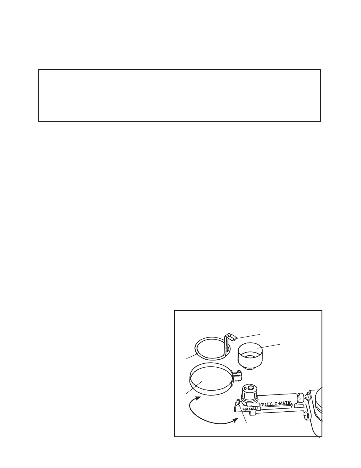
Use of Waxing Cup and
Loop Heat Conductor
The Waxing Cup t and the Loop Heat
Conductor y are optional accessories.
Remove the Pilot Shield 1 and
connect the small loop built into the
outer circumference of the Waxing Cup
over the Post for the Waxing Cup 3.
The Loop Heat Conductor is placed
into the Waxing Cup, circular side
down, and the Loop Heat Conductor
Stem u is positioned above the
Pilot Light, or main burner, flame to
transfer heat down into the wax cup for
softening and keeping wax at a desired
consistency. Replace the Pilot Shield
after attaching the Waxing Cup.
1
y
t
3
u
Figure 3: Use of Waxing Cup
and Loop Heat Conductor
R
O
T
A
T
E
Page 6
Gas Conversion
Should you desire to operate your Touch-O-Matic® bunsen burner on a gas source
other than the one identified on the body of the Touch-O-Matic® burner and the
Gas Nozzle =, order and install a replacement nozzle. The Gas Nozzles available
are: “BUT” for Butane Gas, Part No. 002835-000; “PRO” for Propane Gas, Part No.
002836-000; “NAT” for Natural Gas, Part No. 002837-000; “MIX” for Mixed Gas,
Part No. 002838-000; and “MFG” for Manufactured Gas, Part No. 002839-000.
WARNING: USE THE TOUCH-O-MATIC® ONLY WITH THE FUEL TYPE STAMPED
ONTO THE GAS NOZZLE AND SPECIFIED ON THE LABEL. DO NOT USE
ACETYLENE. WITH PROPANE OR BUTANE, USE A PRESSURE REGULATOR.
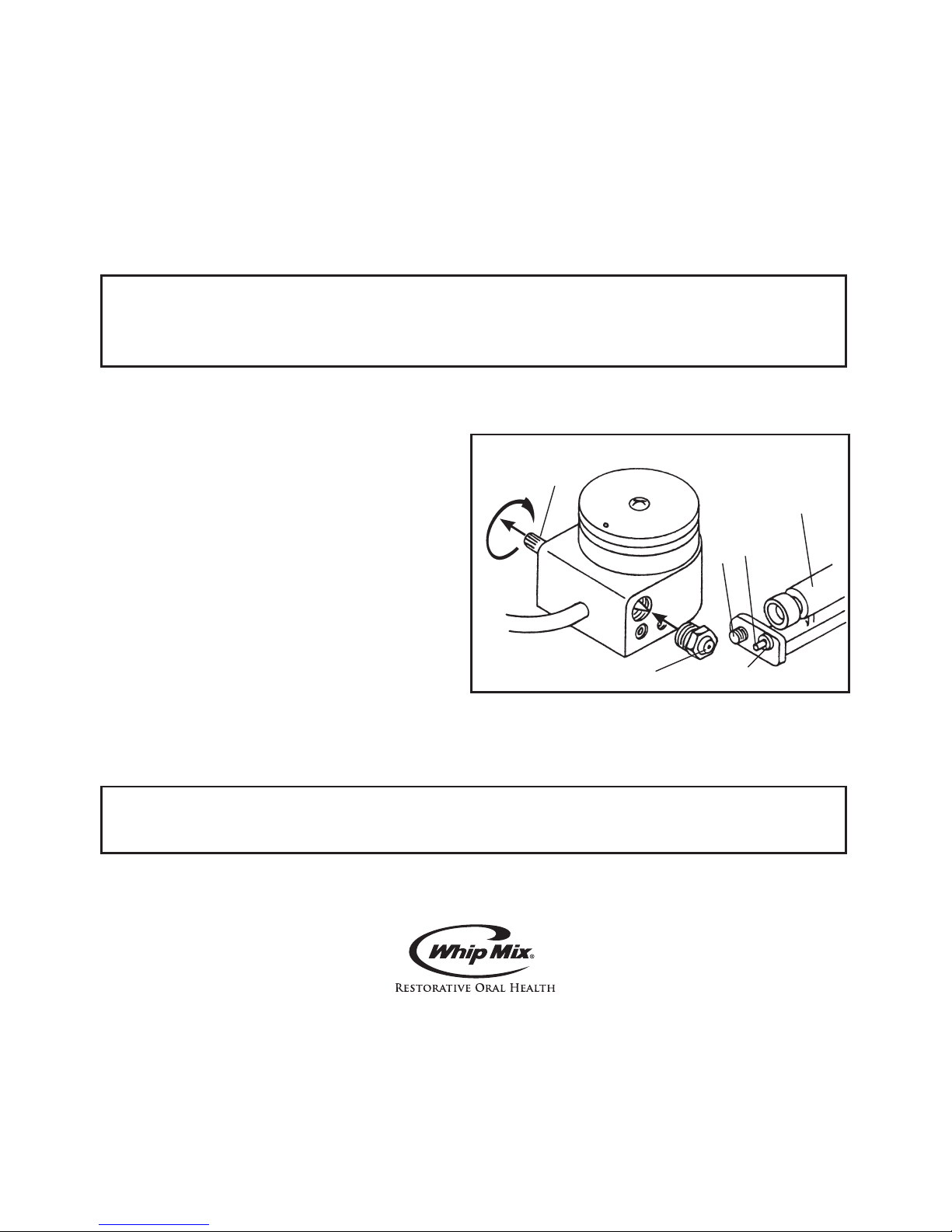
Replacing the Gas Nozzle
Turn the gas supply off and disconnect
the burner from the gas line. Turn
the Gas Adjustment Thumbscrew 8
counterclockwise to its stop. This backs
the needle valve away from the orifice of
the Gas Nozzle = and helps assure that
it will not be damaged while another gas
nozzle is installed. Use care to not bump
the exposed tip of the needle.
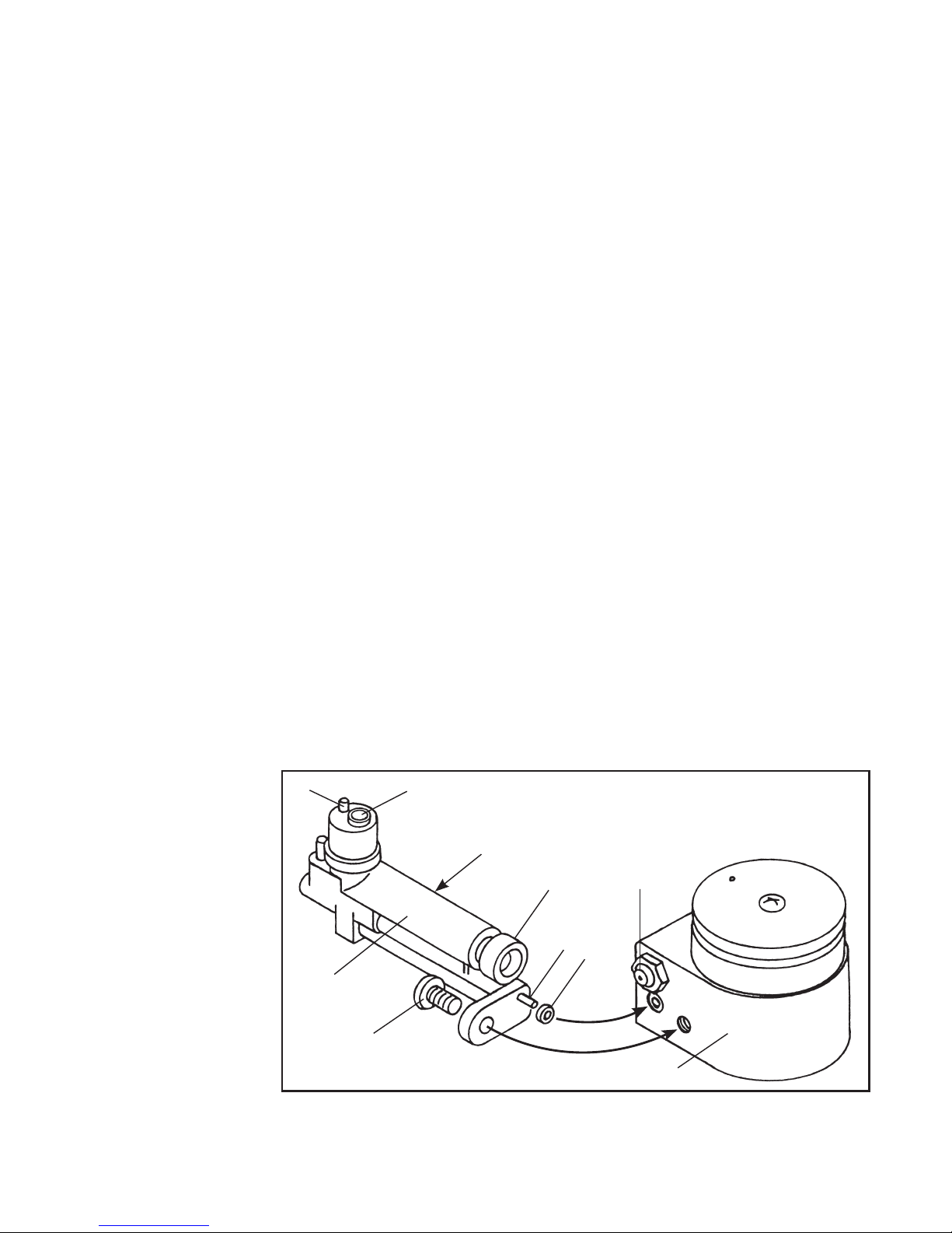
Remove the Screw for Detaching the
Burner Assembly 6 and separate the
Burner Assembly 5 and the Valve
Housing7. Use a 9/16” wrench to unscrew the Gas Nozzle = and replace the old
Gas Nozzle with the new Gas Nozzle. Reattach the Burner Assembly to the Valve
Housing.
WARNING: Make certain the “O” Ring w on the Pilot Inlet e is in place,
otherwise the burner will leak gas.
Place a new label that identifies the type of gas to be used with the burner over the
original label on the burner.
Whip Mix Corporation - West
1730 East Prospect Rd., Suite 101
Fort Collins, CO 80525
Toll-Free: 800-201-7286
Fax: 970-472-1793
www.whipmix.com
Whip Mix®, Touch-O-Matic®, and logos are registered trademarks and Hanau™ is a
trademark of Whip Mix Corporation.
©2008 Whip Mix Corporation FN 339303-F AD R0808
Figure 4: Replacing the Gas Nozzle
8
=
w
6
5
e
 Loading...