

Page 1
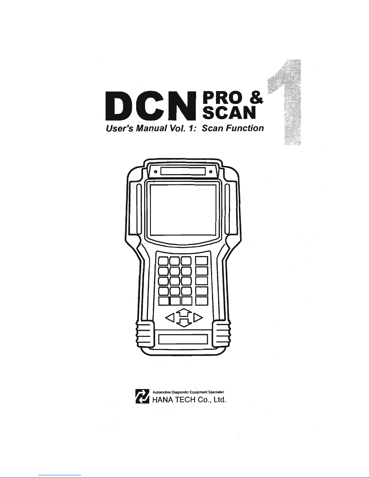
DCN
PRO
&
seAN
User's Manual Vol. 1: Sean Funetion
i
01
. lo
Page 2

DCN
PRO
&
seAN
User's
Manual
Vol. 1: Sean
Funetion
o I I o
0000
0000
0000
0000
DDDO
<]-0[>
~
Page 3
SAFEn
ANO
WARRANTY
1.
SAFETY
INSTRUCTIONS
1 - 2
11.
SAFETY
PRECAUTIONS
1 - 4
111.
WARRANTY
SERVICE
1 - 6
Page 4
8 HANATECH CO., LTD.
Safety
and
Warranty
About this Manual
AII
rights reserved by HAN A TECH Co., Ud., Gumi, Korea.
The contents
of
this manual are the result of cOntributions by dozens
of individuals all who have added their vital expertise and experience to
the evolution of the contents of this manual.
The information contained
in
this manual may contain printing errors
and is subject to change without notice according to product upgrade.
HANA TECH shall not be liable
for
errors contained herein
or
for
incidental or consequential damage
in
connection with the furnishing,
performance, or use of this material.
No part of this manual may be photocopied, reproduced, or translated
to another laRguage
in
any way without the prior written consent of
HANA TECH Co
.,
Ud.
Using this Manual
It
is
recommended that the user become familiar with the
operating procedures, terminologies and information contained
within this user's manual. This will help to increase the user's
effectiveness with this equipment.
Vehicle system familiarity
While this equipment provides very powerful functions with extensive
vehicle coverage, it cannot replace knowledge and skill.
To
get the
most out of this equipment, a full understanding of vehicle systems
is
required.
It
is
recommended that the equipment be used
in
conjunction
with the original service manual for the vehicle being tested.
The equipment
is
designed for use by trained service personnel and
this manual assumes that the service technician who is going to use this
equipment has a familiarity with vehicle electronic control systems,
however, the latest service manuals and bulletins should always be
referenced before using this equipment.
Chapter 1 - 1
Page 5

For DeN Scanners
1.
SAFETY INSTRUCITONS -----------------------
Thank you for purchasing DCN scanners.
To
get the maximum performance of
the equipment, please carefully read this manual first, and keep it at hand.
On delivery inspection
When the equipment is delivered, a check should be made for any damaged or
missing components. If the unit
is
damaged or fails to operate according to the
specifications, contact your local distributor or the manufacturer, HANA TECH CO.,
LTD., Hana bldg. , 80-1 Songjung-dong, Gumi-shi, Kyung-buk Republic of Korea 730-
090.
In
the unlikely event the equipment requires shipping back to the manufacturer,
please use the original packing material.
Safety symbols
The following symbols are used throughout this manual :
&
This mark means that dangerous consequences may
DANGER
arise, with the possibility of death or serious injury
to
the
user, if the machine
is
handled incorrectly.
This mark means dangerous consequences may arise,
&
WARNING
with the possibility of somewhat serious injury to the user
and or damage
to
the machine and facilities, if the
equipment is handheld incorrectly.
SYMBOL Description
This symbol
is
affixed
to
locations on the equipment where
&
the operator should consult corresponding topics
in
this
manual (which are also marked with the
'!\
symbol) before
using relevant functions
of
the equipment.
In
the manual,
this
symbol indicates
explanations
that are particularly
important that the user
is
expected to read the manual before
using the equipment.
---
This symbol represents
DC
(Direct Current)
Chapt
er 1 - 2
,
Page 6

8
HANATECH
CO.,
LTD.
Safety
guideline
In
order to ensure proper operation and satisfactory performance, observe the
cautions listed below.
& DANGER
This equipment
is
designed
to
comply with IEC61
01
O~
1 safety standards, and
has been tested for safety prior to shipment. Excessive high voltage measurement
or improper operation could result
in
personal injury, as well as damage to the
equipment or the vehicle. Please read this manual carefully and be sure that you
understand its contents befare using the equipment.
The manufacturer disclaims all responsibility for any accident except for that
resulting due to defect
in
its product.
~--
--
----.----
-----------
---------------------------~
-----
-
----
!i
\ WARNING
L~
For safety reasons, this equipment should not be used
to
measure circuits carrying more than 30Vrms or 42.4 V peak.
To
avoid electrical accident that could result
in
injury or
death , do not measure voltage
in
excess
of
these limitations.
Maximum rated measurable voltage
is
30Vrms or 42.4V
peak.
Ch<1pter 1 - 3
Page 7

For DeN Scanners
11.
SAFETY PRECAUT10NS -----------------------
DANGER
When an engine is running, keep the workshop area WELL
VENTILATEO or attach a building exhaust removal system
to
the
engine exhaust system. Engines produce carbon monoxide, an
odorless and poisonous gas that causes slower reaction time
and may lead to serious injury or death.
WARNING
Brakes and wheel blocks
Apply the hand brake and block the wheels before using the test
equipment.
It
is
highly recommended
to
block the wheels on
front-wheel drive vehicles beca use the hand brake does not hold
the driving wheels.
Orive Test
Do not drive the vehicle and operate the test equipment at the
same time. Any distraction may cause an accident. Have one
person operate the test equipment
while the other person drives
the vehicle.
-------
--
r~
Never place the test equipment
in
front of you when driving the vehicle because the
test equipment
may
hit your body and cause serious injury when
the air bag inflates.
Do not try to test the SRS air bag system while driving the
vehicle as unintended air bag inflation may result.
Chapt
er 1 - 4
Page 8

8 HANATECH CO.,
LTD.
Engine Compartment
Maintain sufficient clearance between moving components or
belts while using the test equipment
in
the engine compartment.
Moving components and belts may catch loose clothing, test
cables or a part of your body and cause damage or personal
injury.
Electrical Components
Always turn the ignition key OFF when connecting or disconnecting electrical
components unless otherwise instructed.
Vehicle Battery
DeN
equipments are designed to prevent damage from reverse polarity battery cable
connection, however, it is always highly recommended to always ensure correct
polarity terminal connection.
Never lay the test equipment on vehicle battery.
You
may short the terminals and may
cause damage to your body, the test equipment or the battery.
To
avoid damaging the test equipment or displaying false data, make sure the vehicle
battery
is
fully charged and the connections
to
the electronic control module are clean
and tight.
The warning messages aboye and the safety messages contained hereinafter cover
situations Hana Tech
is
aware of. Hana Tech cannot know, evaluate or advise you as
to
al!
of the possible hazards.
You
must make sure that any conditions
or
service
procedures encountered do not jeopardize your personal safety.
Chapter
1 - 5
Page 9

For DeN Scanners
III.
WARRANTY SERVICE
Warranty Period
In
principie, DCN products are warranted
to
the consumer to be free of defects
in
material and workmanship for the period of 3 years after the date
of
purchase.
If the product
is
found defective during this period, the product can be returned to
Hana Tech and will be repaired or replaced free
of
charge.
Freight and repair Cost
For the repair
of
head unit, Hana Tech covers the freight cost for the service during
one year from the date
of
purchase, and you can send the troubled unit
to
your local
distributor without having
to
pay the freight cost.
You
should consult with your local
distributor about the validity
of
remaining warranty period before sending the unit.
For the remaining two years, you are liable for any international cost incurred. Repair
or replacement will be provided free
of
charge.
When the warranty period
is
expired after three years, the customer must pay the
round trip freight and the repair or replacement cost.
Upon delivery
Hana Tech inspects all the ordered product parts and components are included
in
the
package before shipment, and includes the original copy
of
pre-shipment inspection
report
in
the box. As soon as the product
is
delivered to you, please ensure
everything you ordered is properly checked and included referring
to
the pre-shipment
inspection report. If there is anything missing or damaged, you must notify the local
distributor immediately within 3 working days from the delivery date for free
of
charge
replacement
of
the parts.
In
case
of
trouble
If you encounter any malfunction or trouble with the equipment, please refer to the
Trouble Shooting chapter
in
this manual. If the problem cannot
be
solved, please
contact your local distributor for assistance . For early identification
of
a fault or error,
Chélpt
er 1 - 6
Page 10
8
HANATECH
CO.,
LTD.
your local distributor will require the following details:
1.
Symptom
of
problem you are experiencing
2. Serial number of the head unit
3.
Vehicle information: Which specific car were you testing when the problem
occurred - Model name, Model year and system
ID
number if available (for Mitsubishi,
Subaru and Suzuki only: Refer
to
Japanese car chapter for details)
Warranty Void
Even
in
the effective warranty period, if the problem
is
found to be caused by any
of
the followings, Hana Tech charges the cost for round trip freight and actual cost for the
service
to
the customer, and the shipment back
to
the customer will be suspended
until the customer's payment
is
duly made
1.
Evidence
of
improper use
or
application
of
the product ignoring the cautions and
warnings stipulated
in
the
user
's manual
2. Infenfional damage
or
modifications
fo
fhe producf
or
user's attempt
fo
repair
without proper authorization
3.
Any
damage caused
by
Force Majeure including
war
and natural disaster
4.
L08S
of
time, inconvenience and other consequential damage
or
108S
Warranty void seal
In
addition to the above mentioned warranty void conditions, warranty service
is
not
provided
in
case the warranty void seal
is
broken or removed.
If you remove the head unit safety boot, you will see a yellow round sticker covering
one
of
the screw holes
in
the back. Please be careful not to break this seal and never
try
to
open the head unit without direct authorization from the manufacturero
Bought
in
other countries
Only the products properly supplied by the contracted authorized local distributors are
recognizable for free
of
charge warranty service. Any equipment bought outside the
contracted national territory
of
your local distributor will be charged for service.
Chapt
er 1 - 7
Page 11

Page 12
SPECIFICATION
ANO
PARTS
1.
SPECIFICATION
......
... oo'
..........
..
2-1
11.
PART LlST
.................
oo
..
2-3
A.
Head unit and basic supplies
2-3
B.
Basic supplies for DCN-PRO
2-6
C.
Diagnostic Adapters
2-9
D.
Software Cartridges
2 - 16
E.
Spare Parts
2
-17
F. Optional Supplies
2
-18
Page 13

Page 14

______
B_H_A_N_A_T_E_C_H_C_O_",_LT_D_"_--'
__
Specification
and
Parts
1.
S p ec ifi ca
ti
on -----------------------------------
A.
Hardware
CPU: 16bit, 33MHz
RAM: 1 Mbyte (SRAM)
Program Cartridge Memory: 128Mbytes Flash Memory
16M bytes cards for optional packages
Display:
320x 240 Monochrome Graphic LCD with Back Light
Key Pad:
24
membrane keys, embossing type
Serial Port: RS232
Printer: General PC printer
Power: DC 8-18V, 800mA or higher
B.
Environmental Specification
Indoor use only
Operating temperature: Max
50
oC
/ 122°F
Maximum relative humidity: 80% (up to
31
°C/88°F) and 50% (40°C/104°F or
higher)
Installation overvoltage categories: CAT
TI
Maximum measurable voltage:
DC
30V Max
Pollution degree 2
Max" Altitude:
Up
to 2000m
Chapter
2 - 1
Page 15

For DCN Scanners
C.
Oscilloscope Specification
(DCN-PRO
only)
4 Channel
Voltage Division: 0.1V - 20V Div
Time Division: Normal
25/.15
- 20sec
Sampling Rate: 500KHz
/2
channel
Measurable Voltage :
OC
±150V Max
D. Multi-meter Specification
(DCN-PRO
only)
Voltage:
OC
30V Max
Frequency: 1 Hz -
100KHz
Out y Cycle:
O - 99.9%
Current:
±128Amp
Voltage Output:
OC
0.00 - 5.00V
Frequency/Duty Cycle Output: 1.0Hz - 1.0KHz
E.
Mechanical Dimensions
Length: 302.
1111U1
/ 12.1"
Width:
171.91i101
/6.8"
Height: 75 .
7U101
/3.1"
Weight:
1.61
<:g
/
3.51b
(head unit only)
Body Color: Dark Grey
Safety Boot Color: Yellow / Blue / Red
AII
specifications are subject to change without notice for the purpose
of
product
and quality improvement.
Chapter
2 - 2
Page 16

________
__
_
~_
.
_H_A_N_A_T_E_C_H_C_O_.,_U_D_.
___
~
11.
Part
List -----------------------------------------
A.
Head
unit and basic supplies
1.
Head Unit (P/N. 1000-0005)
Made
of
strong ABS resin, each unit has
passed internal impact test before shipment.
As the inner surface
is
coated with anti-
electromagnetic interference material,
it
neither interferes the other electronic
devices nor gets interfered by the other
equipments.
2.
Safety Boot (P/N. 2002-0030)
Flexible plastic cover that protects the head unit from physical,
chemical and electrical damage
Yellow boots are used for DCN-PRO, and blue and red boots are
also available upon distributor's demando
\
/
)
C
hapt
er 2 - 3
Page 17

For
DeN
Scanners
3.
Carry Case (P/N. 3003-0003)
Provides convenient transportation
and the protection
of
the head unit
and other components from outer
physical
impact during
the
transportation and storage. Carry
case
is
provided when purchasing the
head unit and at least one software
package together.
and
dial lock
In
cludes keys
4.
Main Data Link Cable (P/N. 3001-0001)
Connects vehicle side OLC and
OCN
head unit for data transmission.
Connecting parts
on
both ends
are exactly same, therefore,
simply put any one end
to
the
head unit, and then hook the
other end to the vehicle side
OLC after connecting
an
appropriate adaptor
5. Power Cable 1 - Cigarette Lighter (P/N. 3000-0004)
Supplies power to the head unit
from the cigarette lighter socket.
Used when OLC
is
located near
the driver or passenger seat and
power is not
supplied through
OLC.
LEO lights on both ends turn ON
when power is properly supplied.
The metal plunger part
in
the end
of
cigarette lighter connector
is
Ch
apter
2 - 4
Page 18

removable by unscrewing for the fuse replacement.
It
may
become
loose over repeated use, therefore, it
is
highly recommended
to
check if
it
is
tightly screwed frequently . A set
of
plunger parts are included
in
the
basic supplies. Refer to spare parts section hereinafter.
The rated voltage and current for this power cable are 12V a
nd
less than
2A
.
6.
Power
cable 2 - Vehic1e Battery (P/
N.
3000-0005)
Supplies power from the vehicle battery when the OLC is located
in
the engine bay or when using the oscilloscope or multi-meter
functions
Connect each
of
the two
alligator clips
to
the battery
terminal
of
the correct
polarity with caution.
Must be used together with
the Power
Cable 1 . Insert
the cigarette lighter adaptor
of
the Power Cable 1 into the socket,
and connect the other end to the head unit.
Red LEO light turns ON when power
is
properly supplied from the
vehicle battery.
Chapter 2 - 5
Page 19

For DCN Scanners
B.
Basic supplies for
DCN-PRO
l. 4 Channel Oscilloscope Adapter (P/N. 3000-0007)
Collects and delivers electrical
signal from the probes to the
head unit for . oscilloscope,
multimeter and ignition pattern
analysis functions.
Refer to the manual book
2 for
further information
2.
Probes (P/N. 3000-0001)
Obtains and transmits voltage signal from electrical wire or sensor
terminal
to
the main unit for the Oscilloscope, Multimeter and
Primary Ignition Pattern
Analysis functions.
Since DCN-PRO supports up
to 4 channels, 4 probes are
provided together for the
maximum utilization of the
function.
Each probe has rubber bands
of
same color
on
both ends for easier
distinction.
These probes directly get voltage signal by applying a probe needle
into the electric wire, which you have to handle with care. Refer
to
the following warning message.
C
hapt
er 2 - 6
Page 20
_-----8--H-A-N-A-T-E-C-H-C-O-o,-L-T-D-o
------
~...
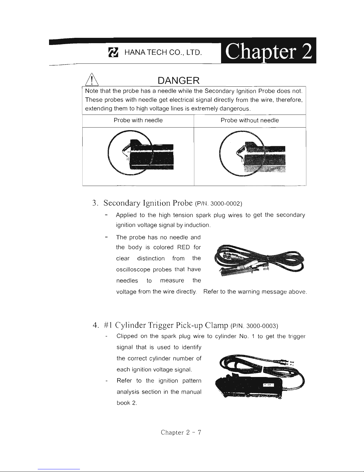
DANGER
Note that the probe has a needle while the Secondary Ignition Probe does no!.
These probes with needle get electrical signal directly from the wire, therefore,
extending them to high voltage lines
is
extremely dangerous o
Probe with needle Probe without needle
3 o
Secondary
Ignition Probe
(P
/N. 3000-0002)
Applied to the high tension spark plug wires to get the secondary
ignition voltage signal by induction.
The probe has no needle and
the body
is
colored RED for
clear distinction from the
oscilloscope probes that have
needles to measure the
voltage from the wire directly. Refer to the warning message
aboye .
40
# 1
Cylind
er Trigger Pick-up
Clamp
(P/
N.
3000-0003)
Clipped on the spark plug wire to cylinder No. 1 to get the trigger
signal that is used to identify
the correct cylinder number of
each ignition voltage signa!.
Refer to the ignition pattern
analysis section
in
the manual
book 2.
Chapter 2 - 7
Page 21
For
DeN
Scanners
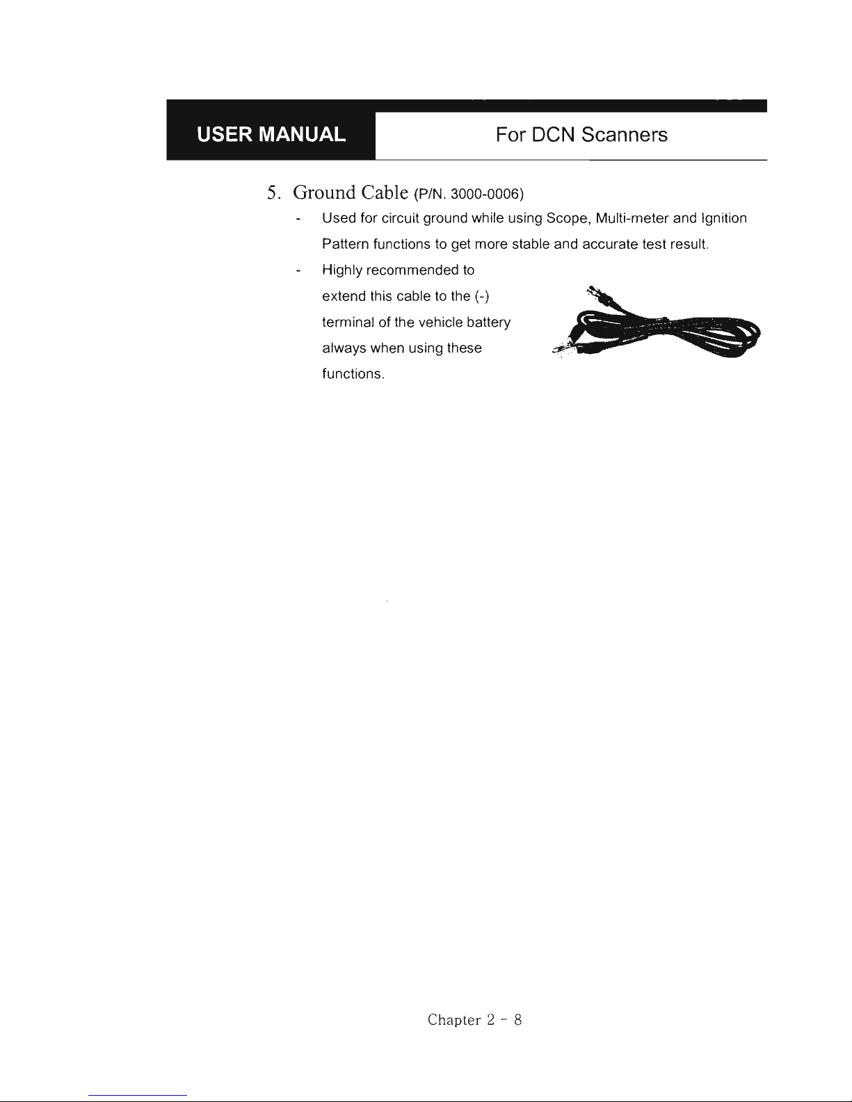
5.
Ground Cable (P/N. 3000-0006)
Used for circuit ground while using Scope , Multi-meter and Ignition
Pattern functions to get more stable and accurate test result.
Highly recommended to
extend this cable to the (-)
terminal of the vehicle battery
always when using these
functions.
Chapter 2 - 8
Page 22

:_---------~--
.
-H-A-N-A-T-E-CH--C-O-.,-U-D-.--~~-
~..
c.
Diagnostic Adapters
Oiagnostic adapters are sold separately, therefore check if all the adapters
you ordered are included
in
the package upon delivery.
There are two types
of
adapters: capsulated and wired types.
Most
of
OCN adapters are capsulated for better durability and storage ,
however, sometimes it
is
difficult or almost impossible to connect the
capsulated adapter to vehicle side OLC when it is located deep inside .
beneath the dashboard. We use wire type adapters for the cars such
as
Hyundai and Kia that we were reported
to
have such connecting difficulties.
Capsule type
l.
OBD2 Standard Adapter
(P/N . 3001-0010)
Used for all OBO generation 2 and EOBO
compatible vehicles . Vehicle side OLC is
generally located near the driver's seat and
most frequently found beneath the dash panel.
2. Toyota / Lexus l7Pin Rectangular
Adapter
(P/N. 3001-0011)
Used for the diagnosis of Toyota and Lexus
of
OBO generation
1.
Vehicle side OLC
of
this type is generally located
in
the engine
compartment.
Chapter 2 - 9
Wire type
Page 23

For DeN Scanners
3. Toyota/Lexus 17Pin Semi-circular Adapter (P/N. 3001-0012)
Also used for the diagnosis
of
Toyota and
Lexus
of
OBO generation 1.
The vehicle side OLC
is
generally found
beneath the dashboard.
Refer to the following warning message
WARNING
.
.'
...
J:
1;-. .-...
~
..
..
f.4
-
:/_
. -
-~--
'
' ,'
........
-'-
.:
.
"" ---
...
..
The appearances of this adapter and
MAZDA
17Pin
adapter
are exactly
same, however, the internal wiring and circuit are different.
Clleck
the
engraved
name
and the
body
color
of the adapter carefully before use.
Improp
er
adapter
connection
may
result
in
serious
malfunction
of
either
control
system
and
DeN
head
unit.
4. Honda 3 Pin Adapter and 2 Pin Jump Wire
(P/N. 3-pin: 3001-0014, 2-pin wire: 3001-0023)
3-pin adapter
is
used for the diagnosis of Honda
cars
of
OBO generat ion 1 that support OTC
read and erase as well
as
data stream.
Older Honda cars have 2-pin OLC that supports
OTC read onl
y.
The jump wire
is
used for these
older cars
to
bridge the 2-pin OLC terminals.
The vehicle s
id
e OLC
is
generally located under
the dashboard or the glove bo
x.
Chapte r 2 -
10
~7.
;""-
Page 24
8 HANATECH ca.,
LTD.
--
----------
------
----------------------------~
5.
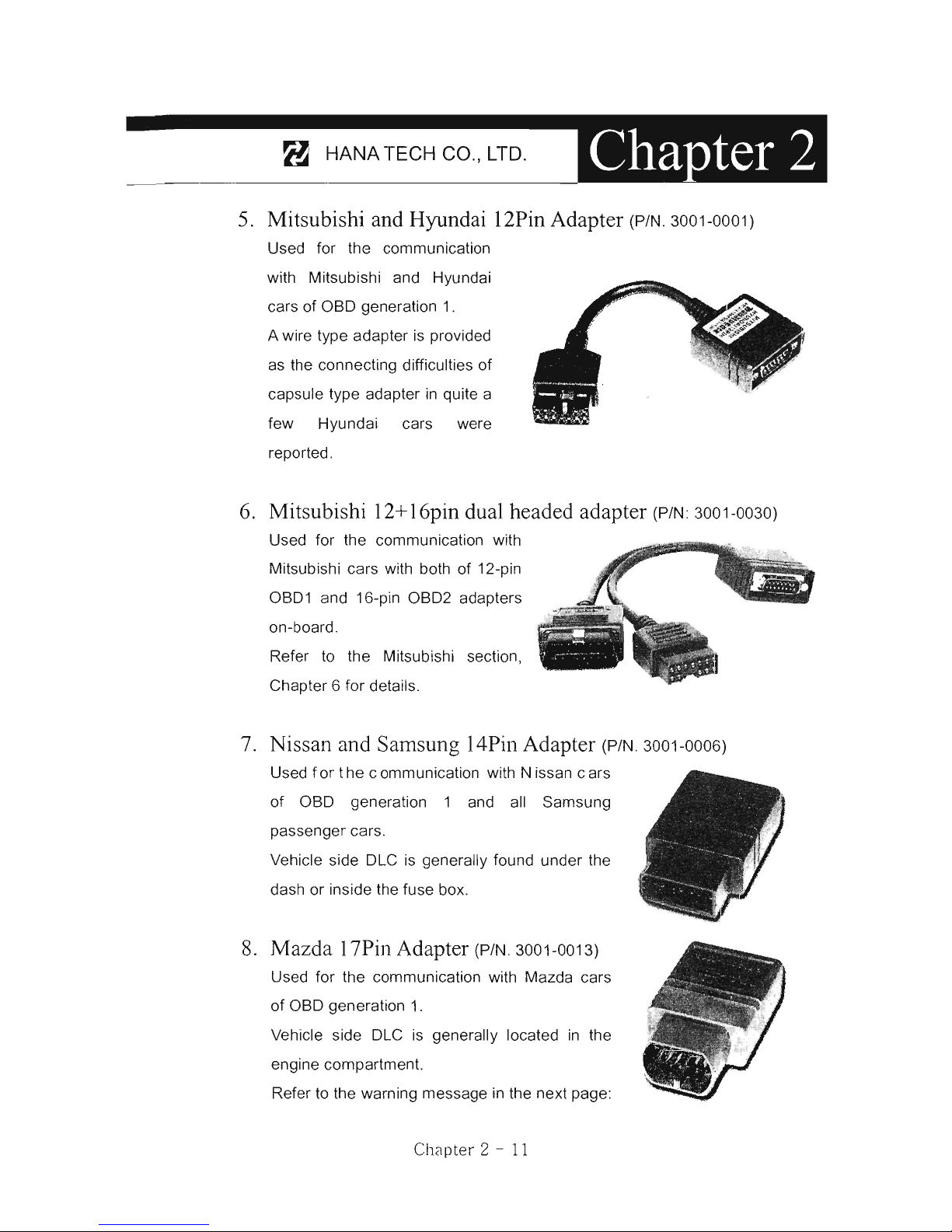
Mitsubishi and Hyundai 12Pin Adapter (P/N. 3001-0001)
Used for the communication
with Mitsubishi and Hyundai
cars
of
OBO generation
1.
A wire type adapter
is
provided
as the connecting difficulties
of
capsule type adapter
in
quite a
few Hyundai cars were
reported.
6.
Mitsubishi 12+16pin dual headed adapter (P/N: 3001-0030)
Used for the communication with
Mitsubishi cars with both
of
12-pin
OB01 and 16-pin
OB02
adapters
on-board.
Refer to the Mitsubishi section,
Chapter 6 for
details.
7.
Nissan and Samsung 14Pin Adapter (P/N. 3001-0006)
Used f or t he e ommunication with N issan e ars
of
OBO generation 1 and all Samsung
passenger cars.
Vehicle side OLC
is
generally found under the
dash or inside the fuse box.
8.
Mazda 17Pin Adapter (P/N. 3001-0013)
Used for the communication with Mazda cars
of
OBO generation
1.
Vehicle side OLC
is
generally located
in
the
engine compartment.
Refer to the warning message
in
the next page:
Chélpter 2 -
11
Page 25

For
DeN
Scanners
WARNING
The appearances
of
this adapter and Toyota
17Pin
SEMI-CIRCULAR
adapter
are exactly same, however, the internal wiring and circuit are different. Check
the
engraved
name
and the
body
color
of the adapter carefully before use.
Improper
adapter
connection
may
result
in
serious
malfunction
of
either
control
system
and
DCN head
unit
8.
Subaru 9Pin Adapter (P/N. 3001-00)
Used for the communication with Subaru cars
of
OBO generation
1.
The vehicle side OLC
is
generally located
beneath the dashboard.
9.
GM Daewoo 12Pin Adapter
(P/N. 3001-00)
Used for the communication with Oaewoo cars
of OBO generation
1.
The vehicle side OLC
is
generally located
beneath the glove box, door side.
10. Kia 6Pin Adapter (P/N. 3001-0003)
Used for the communication with old
Kia cars
of
OBO generation 1 .
Only the Diagnostic Trouble Code
reading function
is
available for the
cars with this type
of
adapter as only
the slow pulse signal
is
transmitted
through the vehicle side OLC .
.
~J
,_0
__
~
. -
.
"~
~,,:-~/
,:,
= :
:.
~~,
..
The split wire
of
the adapter
is
to be connected to the ground terminal of
the vehicle side OLC .
Chapt
er 2 - 12
Page 26

__
---------
~---H-A-N-A-T-E-C-H-C
-
O
-.,
-
L-T-D-.
--~
~--
~
••
11.
Kia
20Pin Adapter (P/N. 3001-0004)
Used for the communication with Kia cars
of
OBO generation
1.
OTC read & erase and data stream
functions are available for the cars
with this type
of
adapter.
Refer to the following warning
message.
& WARNING
The appearances
of
Kia 20Pin
adapter
and
Ssangyong
20Pin
Rectangular
I
adapter
are exact ly same, however, the internal wiring and circuit are different. !
Check the
engraved
name
and the
body
color
of
the adaptel· carefully before i
use.
Improper
adapter
connection
may
result
in
serious
malfunction
of
either
control
system
and
DeN
head
unit
12. Ssangyong
20Pin Rectangular Adapter (P/N. 3001-0005)
Used for Ssangyong cars of OBO
generation
1.
Vehicle side OLC
is
located
in
the
engine compartme nt.
Refer to the warning aboye.
13. Ssangyong 14Pin Circular Adapter
(P/N.3001-0007)
Used for old Ssangyong cars of OBO
generation 1.
Vehicle side OLC
is
located
in
the engine
compartment.
Ch;\pt er:2 - 13
Page 27

For
DeN Scanners
14.
Holden 6 Pin
Adapter(P/N.
3001-0023)
Used for Australian Holden
of
OBO
generation
1.
Japanese cars such as Toyota and Nissan
assembled
in
Australia with Holden built
engines
may
have this type of adapter, too.
Vehicle side OLC
is
generally located
beneath the glove box
to
the center facia.
15
. GM Opel 1
OPin
Adapter
(P/N
. 3001-0019)
Used for the communication with
Opel cars
of
OBO generation 1.
Also available with OCN Australian
Holden, South American Opel and
European
packages.
Vauxhall
software
Vehicle side OLC
is
generally
located
in
the fuse box beneath the dashboard or near the parking brake.
16.
Ford 20 Pin
Adapter(P/N.
3001-0020)
Used for the communication with Ford cars
of OBO generation 1, including Australian
and British Fords.
Vehicle side OLC
is
generally located
in
the
fuse box beneath the dashboard.
Chapter
2 - 14
Page 28
8 HANA TECH ca., LTD.
-
----------
--------------------------------
~
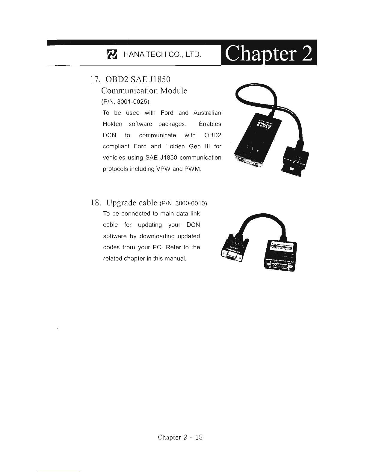
17.
OBD2
SAE
11850
Cornmunication Module
(P/N.3001-0025)
To
be used with Ford and Australian
Holden software packages. Enables
DeN
to
communicate with
0802
compliant Ford
and
Holden Gen
111
for
vehicles using SAE
J 1850 communication
protocols including VPW and PWM .
18. Upgrade cable (P/N. 3000-0010)
To
be connected to main data link
cable for updating your
DeN
software by downloading updated
codes from your
pe
. Refer to the
related chapter
in
this manual.
Chapter
2 - 15
Page 29

For
DCN
Scanners
D.
Software Cartridge
Contains vehicle information and operating software for DCN
scanners.
The appearance and measurements for DCN cartridges
complies
with standard PCMCIA, however, inner circuits are
of
Hana Tech's
own designo Therefore, you can neither use it with the other
equipment nor copy its contents to the other standard
PCMCIA .
Various software packages are available on demand by the
combination
of
a variety
of
software. Therefore, please check if each
software cartridge provides the vehicle coverage you have ordered.
WARNING
MAKE
SURE
TO TURN POWER OFF BEFORE REMOVING OR INSERTING
A CARTRIDGE . It
is
extremely dangerous to insert or remove a PCMCIA card
while the head unit
is
turned on. Both PCMCIA card and head unit can be
critically damaged and break down. Always turn power
off
by pressing the
[POWER] key or removing power supply cable from the head unit befare
inserting or removing a PCMCIA card
..
Chapt er 2 - 16
Page 30

_-----B--H-A
-
N-A-T-E-C-H-C-O-.,-L-T-D-.
______
iII'"
E.
Spare Parts
1.
DeN-seAN
Extra
fu
ses
(P/N. 3008-0003)
For the replacement of the fuse located inside
the_
cigarette lighter power cable.
You
can also replace
it
with a fuse
of
which rated current
is
2 Ampere or
less.
Spare
cigarette
lighter
power
cable
plunger
parts
A set
of
spare parts for replacement when
the original parts are lost.
2.
DeN-PRO
Wrench
for
probe
needle
replacement
(P/N. 3008-0002)
•••
A screw driver type
hexagon wrench used
for the
replacement of
the probe needle.
------------
....
1 -
-
Extra
probe
needles
(P/N. 3008-0001)
A couple of short spare needles and
extended needle units.
You
can use any metal sawing
needle when you run out of spare
needles.
Chapter
2 - 17
Page 31

For DeN Scanners
F.
Optional Supplies
l. Current Ampere Meter Clamp
(P/N.3000-0008)
Sold separately for measuring current
ampere . Made by Summit, Korea.
2.
Printer Cable (P/N. 3000-0009)
To
be connected between head unit
RS232 port and printer to enable direct
interface with a PC printer.
Compatible with the printers that support
PCL mode, and Hewlett Packard ® is
highly recommended.
3.
Host-Pro PC Interface Package
Consisted
of
a software installation CD (P/N. 3005-0002), 5 meter
USB cable (P/N. 3000-0014) and communication module (P/N.
3000-0013) that converts RS232 communication to USB.
Enables realtime PC interface
of
DeN
scanners . Refer to
the PC interface section of this
manual and the separate
HOST-PRO user manual for
further information.
Chapt
er 2 - 18
Page 32
OPERATING
DeN-PRO
1.
GETTING STARTED
..........
".o
..
.o
.o
..
3-1
A.
Head unit
3-1
B.
PCMCIACard
3-2
C.
Main OLC Cable
3-4
o. Power Supply
3-5
E. Contrast
3-7
11.
CONTROL KEYS
............
.o
.o.
3-8
A.
Key pad
3-8
B.
Making Selection
in
the menu
3-8
C.
Function keys
3-9
111.
CONFIGURATION
.......................
3 -
11
A.
Software Information
3 -
11
B.
System Test
3
-12
C. Speci
al
Functions 3 - 13
Page 33

Page 34
_---
--
8-
'
_H_A_NA_TE_C
_
H_C_O_"_,
L_T_D_" _--'_
Operating
DeN-PRO
1.
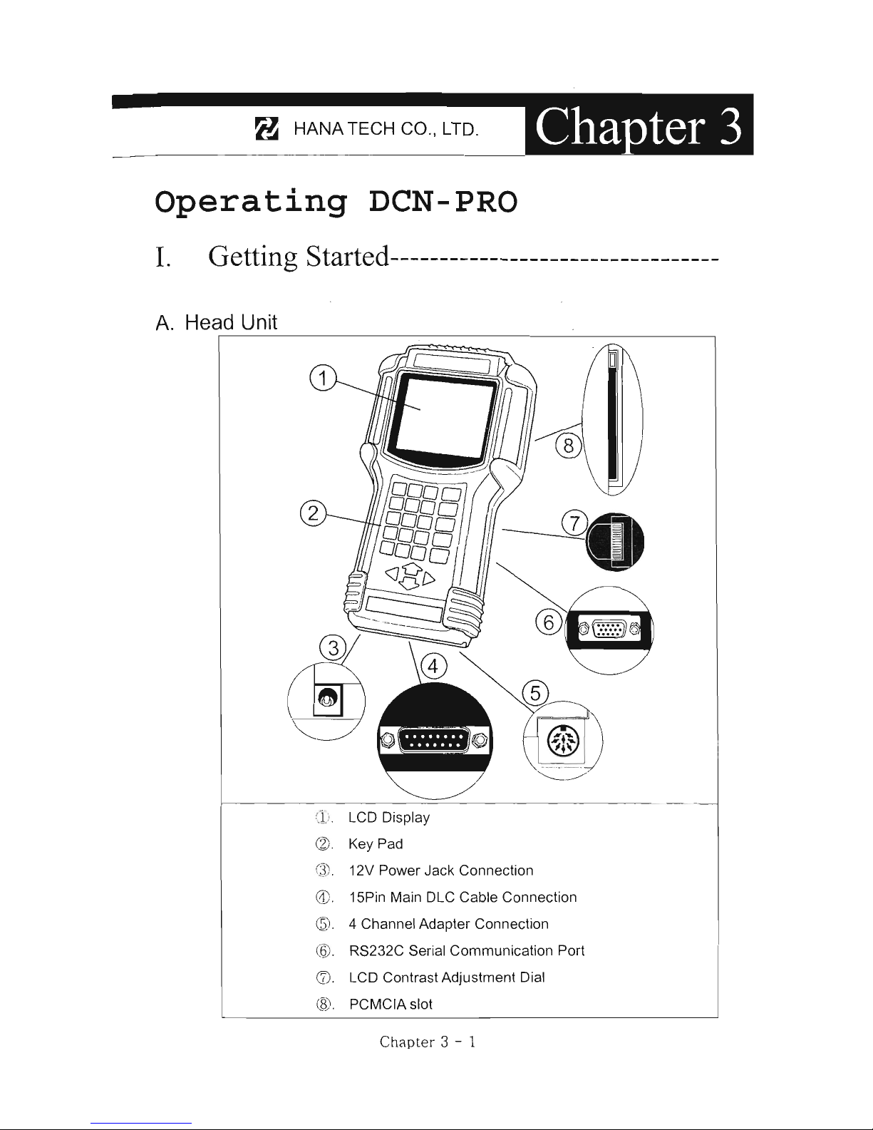
Getting Started---------------------------------
A.
Head Unit
Oí
LCD Display
@ Key Pad
C
J}
12V Power Jack Connection
®
0)
. 15Pin Main DLC Cable Connection
(5:
1. 4 Channel Adapter Connection
(6)
" RS232C Serial Communication Port
(f). LCD Contrast Adjustment Dial
(S).
PCMCIA slot
Ch
apter
3 - 1
Page 35

For DCN Scanners
B.
PCMCIA card
WARNING
Insert or remove PCMCIA card when DCN-PRO power
is
turned
OFF
Serious damage to head unit and PCMCIA card may occur in case of
insertion or removal
of
PCMCIA card while DCN-PRO
is
operating.
l.
Inserti
on
Slowly insert the PCMCIA card into the slot and press firmly until it clic
ks
into
place.
WARNING
Make sure not to insert the PCMCIA card upside down.
The card will not fit into the place when inserted upside down, however, if
you press it too hard applying excessive power, the frame and
connecting pins inside
DCN-PRO may be broken or bent.
Free
of
charge warranty service
is
not provided
in
this case.
Chapter 3 - 2
Page 36

_---
- -8-'
_H_A_N_A_T_E_C_H_C_O_.,_L_T_D
_.
__
2.
Removal
1. Press the eject buUon to release the PCMCIA card from the tight connection with
the inside frame and pins.
2.
Hold the PCMCIA card gentiy and pul! it slowly out
of
the slot.
Chapter 3 -
;\
Page 37
For
DCN Scanners
C.
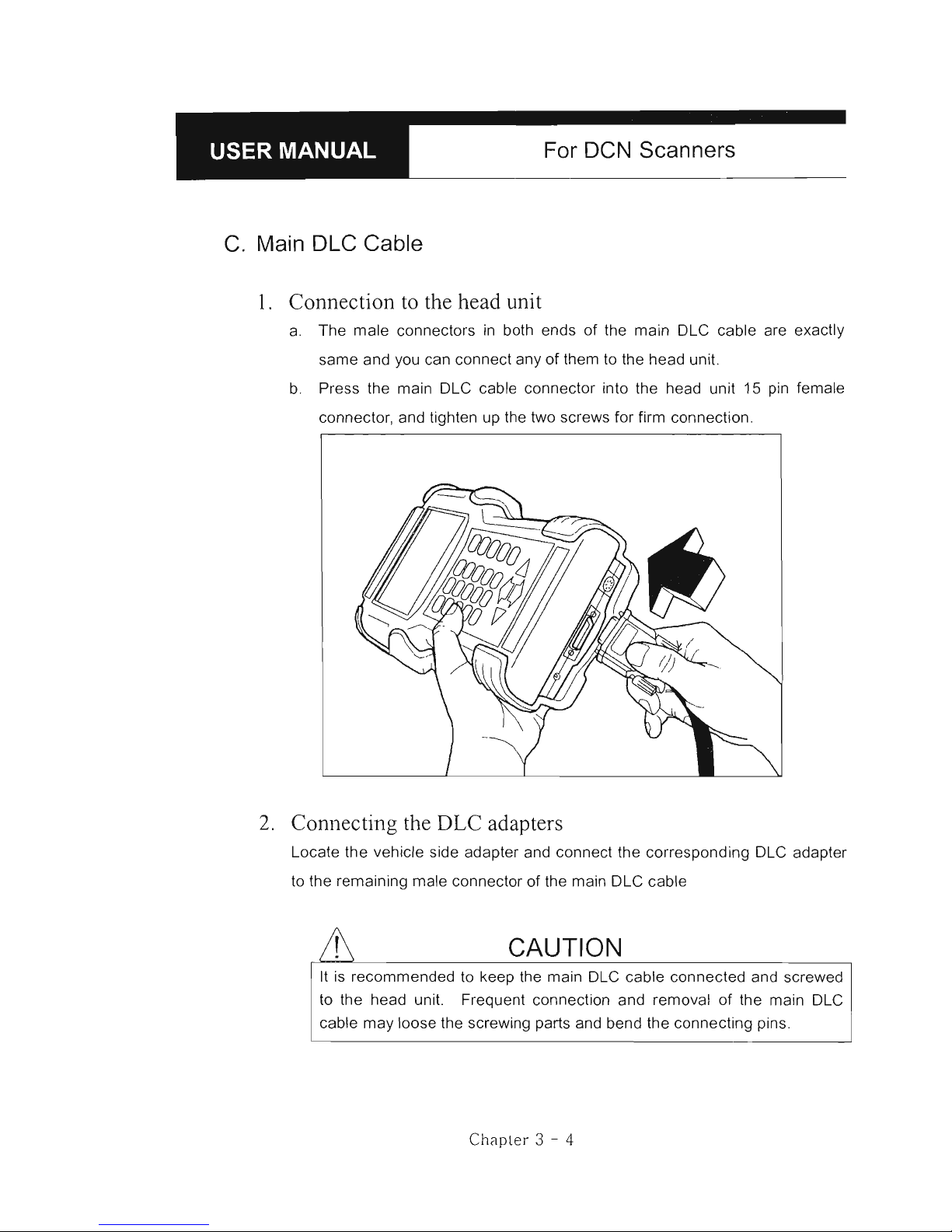
Main DLC Cable
1.
Connection to the head unit
a.
The male connectors
in
both ends
of
the main
OLe
cable are exactly
same and you can connect any
of
them
to
the head unit.
b. Press the main OLe cable connector into the head unit 15 pin female
connector, and tighten up the two screws for firm connection.
2.
Connecting the DLC adapters
Locate the vehicle side adapter and connect the corresponding
OLe
adapter
to
the remaining male connector
of
the main
OLe
cable
CAUTION
It
is
recommended to keep the main OLe cable connected and screwed
to the head unit. Frequent connection and removal
of
the main OLe
cable may loose the screwing parts and bend the connecting pins.
Chapler 3 - 4
Page 38

2
__
----8--H-A-NA-TE-C-H-C-O-.-'
L_T_D_.
__
_
D.
Power supply
l.
Power supplied through DLC adapter
12V battery power
is
supplied through all OLC adapters except GM/Oaewoo
1
OPin
and Mitsubishi/Hyundai 12Pin adapters
2.
Cigarette hghter
a.
Use the cigarette lighter cable when power
is
not supplied through the
OLC adapter.
b. Insert the cigarette lighter connector into the socket, and check
if
the red
LEOs
in
both ends
of
the cable are ON.
c.
Insert the metal power jack into the head unit power socket.
Chélpt er
:3
- 5
Page 39
For
DeN
Scanners
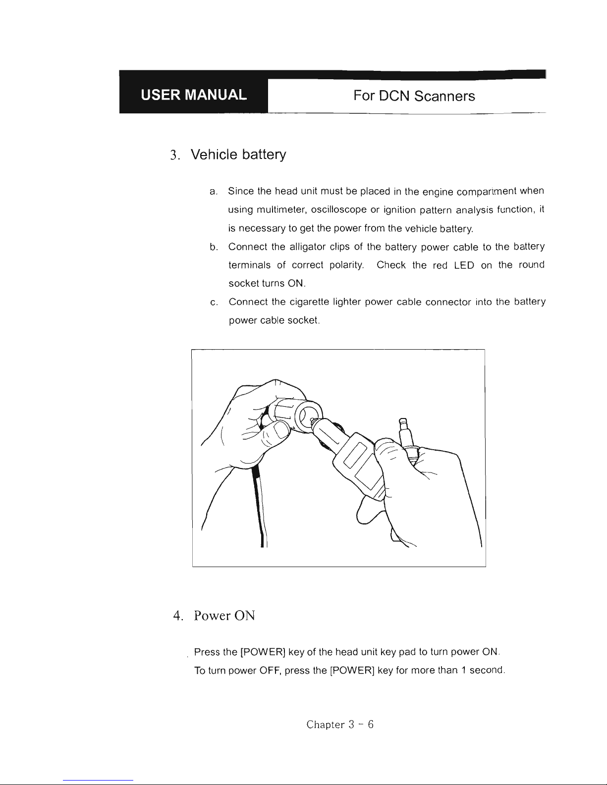
3. Vehicle battery
a. Since the head unit must be placed
in
the engine compartment when
using multimeter, oscilloscope or ignition pattern analysis function,
it
is necessary to get the power from the vehicle battery.
b.
Connect the alligator clips of the battery power cable to the battery
terminals
of
correct polarity. Check the red LED
on
the round
socket turns ON.
c.
Connect the cigarette lighter power cable connector into the battery
power cable socket.
4.
Power
ON
Press the [POWER) key
of
the head unit key pad to turn power ON.
To
turn power OFF, press the [POWER) key for more than 1 second.
Chapter
3 - 6
Page 40
:_-----8
-'
_H_A_N_A_T_E_C_H_C_O_.,_L_T_D_.
------'_
E.
Contrast
a.
The Leo display is sensitive to the temperature.
It
becomes too faint when it
is
cold and too dark when it is hot.
b. If the screen
is
too faint or too dark to read, you can adjust the contrast by
turning the contrast dial in the right side
of
the head unit.
c.
In
case of any trouble with the display, please refer to the Trouble Shooting
chapter
in
this manual.
Chapt
er
3 - 7
Page 41

For DeN Scanners
11.
Control Keys -----------------------------------
A.
Keypad
The keypad is made of chemistry
proofing PVC material that
prevents contamination and
damage from hazardous oily
workshop environment.
The membrane keypad
is
designed and tested
to
maintain
its normal operation over
million time key press for each.
Each key is raised for better
tactile feel. The keypad has total
of
24
keys.
B.
Making selection
in
the menu
1.
Numeric
Keypad
a.
Simply press the corresponding number
b. This
is
available only when you are selecting
an
item
of
which number
is
9 or less. For more than 10, you should locate the highlight ed bar
on
the desired item and press the [ENTER]
key.
Chapter 3 - 8
Page 42
:_-----~-H-A-N-A-T-E-C-H-C-O-.,-LT-D-.---'-
2.
Arrow keys
Page Up/Down
Seroll Up/ Down
a. Seroll up and down the highlighted bar
in
the menu by pressing Up/Down
arrow keys and press
the
[ENTER] key to eonfirm theseleetion.
b. If the menu has more than
12
items, you may have to seroll
up
or down
the pages to make seleetion.
You
do not have to pound
on
Up/Down
arrow keys to seroll the whole page. Simply pressing the Left or Right
arrow key will shift page to page. Move the highlighted bar by pressing
the up/down keys when the desired item appears on the sereen, and
press the [ENTER] key.
C.
Functían keys
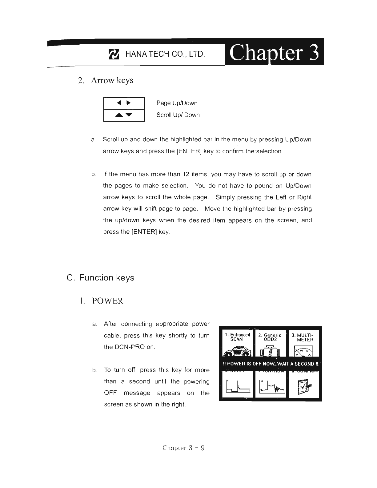
1.
POWER
a. After eonneeting appropriate power
cable, press this key shortly to turn
the
DeN-PRO
on.
b.
To
turn off, press this key for more
than a seeond until the powering
OFF message appears
on
the
sereen as shown
in
the right.
C
hC1pt
er 3 - 9
1. Enhllnced
2. Generic
3.
MULTI·
seAN
0802
METER
Page 43

For
DeN
Scanners
2.
Back light
[-:9:-
]
a. LCD module
of
DCN-PRO has an illuminating back panel for better
legibility in dark or shady places.
b. Press this button to turn the back light ON and OFF.
3.
ESC
Used to abort an operation
of
DCN-PRO or move to the upper level menu.
4.
HELP
a. DTC Read
When a trouble code
is
detected, you can press this key to view the
detailed information
of
the DTC.
DTC definition, DTC registration conditions and check points are
provided (For Korean and
Malaysian cars only as
of
May, 2003)
b.
Service Data (Data Stream)
While live data
is
being displayed
on
the screen, select a live data
item by moving the highlighted bar, and press this key to view the
detailed information about the selected item.
Standard
value and technical explanations are provided. (For
Korean and Malaysian cars only as of May, 2003)
5.
PRlNT
a.
When a printer
is
connected to DCN-PRO via printer cable, press this
key to print out the current display : DTC list, a set
of
data stream,
oscilloscope waveform or ignition pattern.
b. Refer to the
Optional Parts section for detailed information on the printer
cable.
Cha
pt
er 3 - 10
Page 44

:
__
---------~---H-A-N-A-T-EC-H--C-O-.,-U-D-.--~~
II!.
Configuration ----------------------------------
Press the [6] key from the initial function menu to proceed to the configuration
menu. You can check the version numbers
of
the software packages contained
in
the PCMCIA card, test the keypad and LCO, set up sound and language
options and download software updates
in
the configuration menu .
1. Enhanced
2.
Generic
3.
MULTI-
seAN
0802
METER
6&I
ID
~
V A
4.
seOPE
5.IGNITION
6.
eONFIG
bb
~
~
CONFIGURATION
l .
SOFTWARE
INFORMATION
2.
SYSTEM
TEST
3.
SPECIAL
FUNCTIONS
System Informatlon
Serial
No
......
70000-000
Model ....... ... DCN-PRO
Languaqe
.......
English
Memory
Card
....
16
MByte
Bootstrap
Code
. . Ver .
300
[2003.4.201
Operating
Code
. . Ver .3 10 [2003.4 .
201
ESC.
HAIN
FUNCTION
[CUSTOHER)
A.
Software Information
When you select [1. SOFTWARE INFORMATION]
in
the configuration menu, a
list of software packages contained
in
the PCMCIA card will appear as below:
SOFTWARE
INFORHATI
ON
SCOPE
V.310
GENERAL
0802
V.201
HYUNDAI
{DOMESTIV.550
HYUNDAI
{NON
USAV.150
KIA
(DQMESTICS)
V.550
KIA
(NON
USA)
V.l50
DAEWOO
VEHICLES
V.550
SSANGYONG
VEHlC
V.550
SAMSUNG
VEHICLE
V.550
2003 .04.20
2003 .04.
1B
2003 .04.29
2003 .
04.29
2003.04 .
21
2003.04.21
2003.04 .
21
2003 .04.
21
2003.04.21
Should you get any update files from your local distributor or from Hana Tech
website , please compare the version number and last update date to check if the
update is necessary.
Chapter 3 -
11
Page 45
For
DeN
Scanners
B.
System Test
You
can test the proper operation of keypad and LCD display.
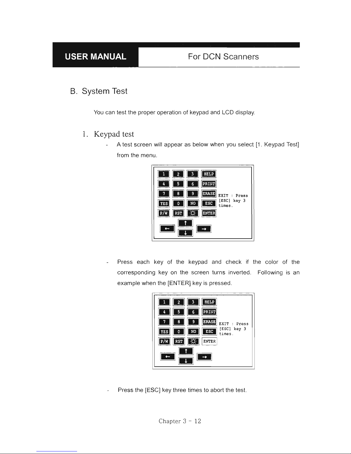
1.
Keypad test
A test screen will appear as below when you select [1. Keypad Test]
from the menu.
Press each key
of
the keypad and check if the color of the
corresponding key on the screen turns inverted. Following
is
an
example when the [ENTER] key is pressed.
Press the [ESC] key three times to abort the test.
Chapter 3 - 12
Page 46
:_------
---
~---H-A
-
N-A-T-E
-
C-H-C
-
O
-
.
t
-U-D-.--~~
2.
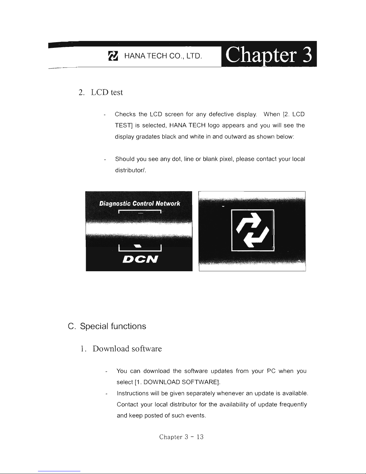
LCD test
Checks the LCO screen for any defective display. When [
2.
LCO
TEST] is selected, HANA TECH logo appears and you will see the
display gradates black and white in and outward as shown below:
Should you see any dot, line or blank pixel, please contact your local
distributor/.
C.
Special functions
l.
Download software
You can download the software updates from your PC when you
select [1. OOWNLOAO SOFTWARE].
Instructions will be given separately whenever
an
update
is
available.
Contact your local distributor for the availability
of
update frequently
and keep posted
of
such events.
Chapte r 3 - 13
Page 47
For DeN Scanners
2.
Language
3.
Sound
You can select provided language. English and Spanish languages
are available for selection as
of
May, 2003.
Hana Tech
is
translating the menu and messages of DCN-PRO
to
various local languages such as Russian, Arabic and Chinese for
convenience
of
non-English speaking customers, and the each
language will be provided as
an
update when the translati
on
is
completed.
You
can toggle ON and OFF the key sound.
4.
Save Configuration
If you have made any change
in
this [Special Function) menu, you
have to save the configuration
to
make such changes effective.
Press the [4] key to save the changes
in
configuration
Chapter 3 - 14
Page 48

DCN-PRO
FUNCIIONS
1.
DIAGNOSTIC TROUBLE CODE
.............
4-1
A.
DTC Read
4-1
B. DTC Erase
4-4
C.
DTC Help Tips
4-5
11.
CURRENT DATA
.............
4-6
A.
Pulse Signal Type
4-6
B. Serial Communication Type
4-6
C.
Data Freeze
4-7
D.
Data Graph
4-8
E.
Help Tips 4 -
10
111.
ACTUATION
TEST
.............
4 -
11
IV. BLACK BOX
4
-14
V.
CONNECTOR LOCATION
4
-20
Page 49

Page 50
8 HANATECH CO.,
LTD.
DeN-PRO
Functions
The functions you can choose when all the test vehicle details are selected
properly are explained
in
this chapter of the manual. The actual list of
available functions may be différent according to the vehicle you want
to
test.
1.
Diagnostic Trouble Code---------------------
A.
OTC Read
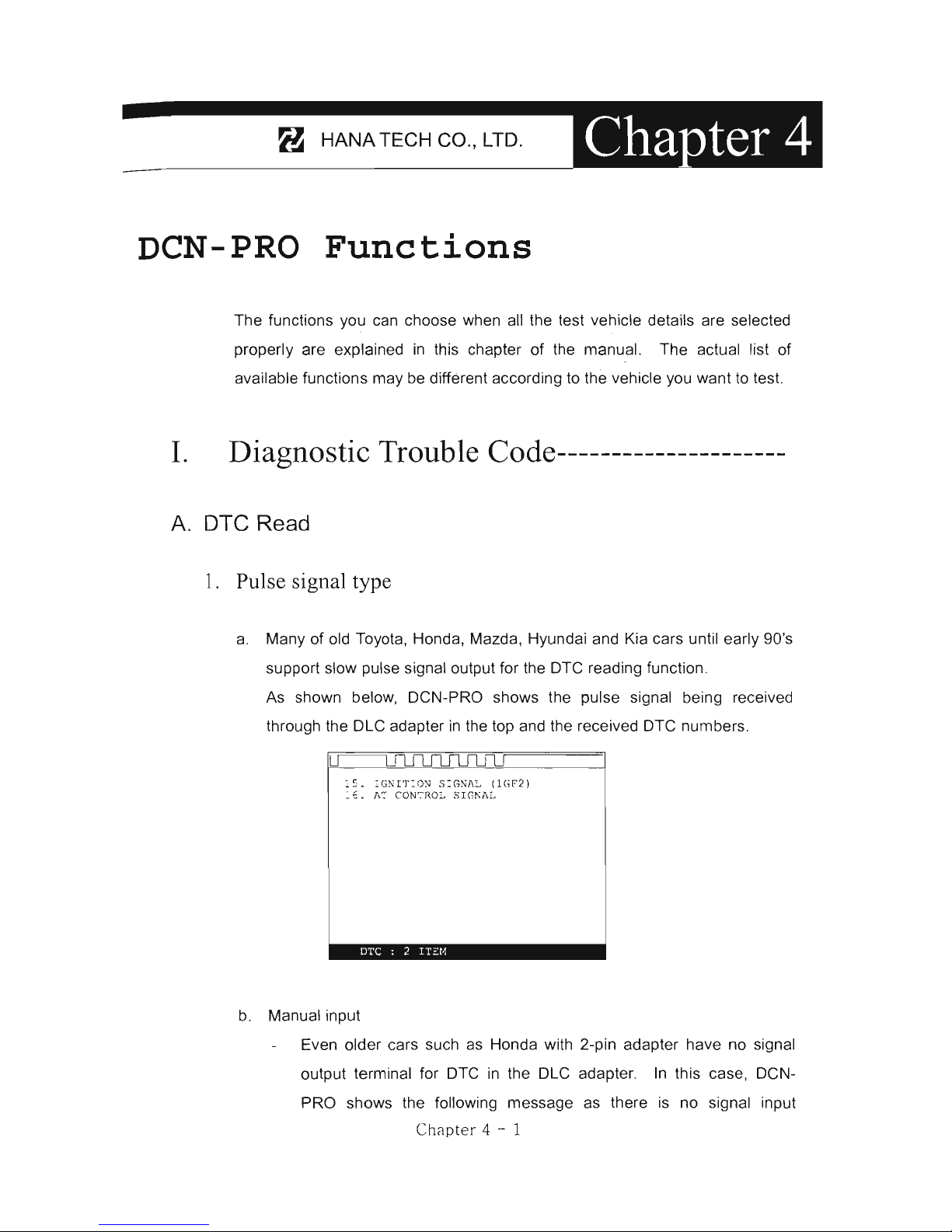
l. Pulse signal type
a.
Many of old Toyota, Honda, Mazda, Hyundai and Kia cars until early 90's
support slow pulse signal output for the DTC reading function .
As shown below, DCN-PRO shows the pulse signal being received
through the DLC adapter
in
the top and the received DTC numbers .
'-5. :GNIT:ON
S:GNi\L (1(;,2)
_~. A
~
CON7ROL
5IGKAL
DTC : 2
n=:N
b.
Manual input
Even older cars such as Honda with 2-pin adapter have no signal
output terminal for DTC
in
the DLC adapter.
In
this case, DCN-
PRO shows the following message as there
is
no signal input
Chapter 4 - 1
Page 51

For DeN Scanners
through the adapter.
Rea
d Fl a
sh Code
as
belo
w:
l . I
nsert Diagnostic
Connector.
2 .
Tur
~
Vchicle
Ignition OK.
3.
Read
Oash
Lig~t rlashi~g.
- No OTC: M
ay
be
~o
blir.king
or
b l
inking
fa~
t
4. Inp
ut 2 digit
DTC code
ro
CONTINü~
,
PRESS
(~NTERJ
OTC:
I72r~
•
You
have to count the MIL flashing
on
the dashboard and manually
input the DTC number to DeN-PRO to view the details as below :
INP~T
OTC
N~MBER
: l e
15
. I GNITION
SIGN1IL (lG
F2 )
OTC : 1
1:'
::[,1
Long flash signals count for tens and short signals for ones . Input
two digits for tens and ones
in
sequence using the numeric keypad.
A flash signal for
acode
is
followed by another if there are multiple
trouble
codeso
Blinking signals for all trouble codes flash
in
sequence, and repeat after a pause.
Long signal: X10
Short signal:
X1
I
~
ON
ON
ON
-
-
-
'--
OTe No.
12
Chapter 4 - 2
Page 52

:_-----8-
'
_H_A_N_A_T_EC_H_C_O_"
_LT_D_,
___
_
c. Others
Generally DCN-PRO reads DTC pulse signal from the diagnostic
adapter and shows the DTC number, title and details automatically.
2,
Serial Cornmunication type
a. Most
of
the cars built
in
1990's or later support serial communication with
a scanner, and the DTC
is
read by bi-directional communication.
b. DCN-PRO sends a command
to
the control module to reply with the DTC
numbers stored
in
memory, and the control module replies thereupon.
Chapter
4 - 3
Page 53

For DCN Scanners
B.
DTC Erase (Clear fault code)
l.
Pulse signal type
a.
Pulse signal type does not support bi-directional serial communication,
therefore, a scanner is unable to send a command to the control module
to erase the DTC information from memory.
These old cars require you to remove battery terminal to clean up
diagnostic information from control module memory.
~5. :G~!'r:ox
S:G~A:,
(lG~2)
_
-::.
. l'
..
'"::
cor,l
~I{.O=-. ':;JC~':¡\:,
~~~;()
'./~.; ~.'\~":}-,~,Y
- :-r,HJl. i N.·
\[
t'
O,,:
:~.
~";I:".co
>,;:~
<~.
DTC
: 2 ITEM
Removing the battery terminal wil! get rid
of
al!
information contained
in
the car stereo and other electronic devices. And it may not effectively
erase the fault codes
in
some cars. Refer to the original repair manual
for further information.
Check if DTC information
is
properly removed by reading the trouble
code again after erasing the codeo
2.
Serial communication type
a. DCN-PRO sends a command to the control module
to
erase DTC
information stored
in
memory, and the control module replies thereupon.
b. Check if DTC information
is
properly removed by reading the trouble
code again after erasing the code
Chapter 4 - 4
Page 54

8 HANA TECH
ca
., LTD.
C.
OTC Help tips
a. Help tips are provided when you press the [HELP] key after locating the
highlighted bar on one of the detected trouble code(s). This function
is
available when DCN-PRO detects one or more trouble code(s)
b. Help tips including trouble code definition, conditions and check points
are provided for all Korean cars and Malaysian cars as of May 2003.
Wiring diagrams are
al
so provided for Korean cars
of
2000 model-year or
older.
DIAG~OSTIC
TRO~BLE
CODE
D
.T.C.
~lc.:
IP0
336)
DTe :-:cndi:-.
i(Jn
~
:
Whcn IG
~cy
ON,
cranklng
i s
possib~e
bu~
thc
rcfc
rcncc mark
lS
~ot
withi~
s:.andard
r~ngc whc~
~o:c
tta~
20GRPM
Fails
afc:
Feedbac~
~o~t:ol
sus
pend~
Icile
s~ccd ad
ap~
atlo~
contro
l s t
ops
(R
c~cr~
:0
che
actua
l
val~Q)
U
s~s
~can
val~c
:nste
ad
of id: e
spcc
¿
char
actc
ris
~lc
curve
.
~slng adap~cd ~arget
a~r vo:~~c
~5
prchih
i~cd(Re
fcr~
to the
a
ct~a:
valu
e )
c. Press the [ESC] key to return
to
DTC list.
Chapter 4 - 5
Page 55

For
DCN
Scanners
II.
Current Data -----------------------------------
(= Data Stream, Live Data, Service Data)
A.
Pulse Signal Type
a. Data stream
is
not generally supported for this type
of
old cars because the
speed
of
pulse signal communication
is
too slow to read the data stream
variables.
b.
Some
of
old Toyota cars using
17
-pin rectangular adapter exceptionally
support data readings as the system supports relatively high speed pulse
signal communication.
B.
Serial Communication Type
a.
Most of control systems with serial communication support data stream
function. Select [Current data] from the menu, then the data readings follow.
b.
Some systems like SRS or ABS may be designed not to support data stream
intentionally by the car make while the other systems are supported. A
scanner
is
a passive tool that reads information from the control system, and
it is unable
to
actively generate information that the system does not provide.
C
hCl
pte
r 4 - 6
Page 56

~
___
------_~--_H_A_N_A_T_E_C_H_C_O_.,_L_T_D.----~
C.
Data Freeze
The [Data Freeze] function places the selected data stream variable
on
top
of
the
LeO
screen so that the user can check and compare desired sensor
values continually without having to scroll up and down.
This function
is
different from 'Freeze Frame Data' function
of
Generic OBD2.
1) Step One
Select a desired sensor using the
[~][
~
1 and the
[A][T]
keys.
2) Step Two
Press the [ENTER] key
to
freeze the selected sensor.
i.e
.,
when
02
sensor and MAP sensor are selected and frozen, these
sensor values will
be
placed at the top of the display as below :
SEI(VIC
F.
C
.~T!·
.
02 SENSOR - - - - - -
---
... -
--
~A
P
SE
NSOR --
----------
02
SENSOR - - -
--------
- -
MAP
SENSOR
------------
946
hIR
TE~P SENSOR
-------
1PS
SENSROR
-----
----
- -
SIEP MOTOR
----
- - - - - - - -
BAT~ERY
VOLTAGE ------
-
IGNIT:ON
S:G
NhL
---
- - - -
COOI,~NT
TE~P
SEN
SOR
---
ENG!NE
RP~
------
- - ----
SHOHI
TEr
·:~·~
rUE
L
TR:~'1
- -
~'lrW
39
.
:"
¡,
13
. 2
\1
OFF
82
"C
'!oOr pm
1O
~
1 : GRl,PH 2 : FUL L
ENTER:
F7X
3) S tep Three
Up to five sensors may be frozen at a time. For example, if the Injection
Tim
e,
which can be shown when scrolled down,
is
selected and frozen,
Injection Time value will be placed below the previously frozen
02
and MAP
sensor.
Chapter
4 - 7
Page 57

D.
Data Graph
For
DeN
Scanners
SERVICE
DlITr,
02 SENSOR
-------------
~~p
SENSOR
------------
INJECTIO:-¡ TIHE --- -
----
ENGINE
RPM
-------- - - - -
SHORT
TERM
FUEL
TRIM
- -
LONG TERM
FL:E:"
TRIM
- - -
I
DLE SWITCH -------
- -
--
?OW
ER
STE
ERI
NG
SWITCH
-
lIIR CONCITINER
SWITCH
-
~8:nV
9/J
6
O.2mS
"7
(;0
r'p:~
101
86
8
FF
•
O
FF
OFF
INJECTION
TIME
--------
O.2mS
3TDC
------------
-
-----
lIIr
CONDITIONER
RELlIY
-
1 : GIU, PH 2 :
FULL ENTER
~
O
FF
FIX
DCN PRO provides the [Data Graph) function for more efficient data
analysis.
a When you press the
[1)
key after locating the highlight bar on the desired
sensor, the sensor data graph will be displayed as shown below.
b You can display up to 3 graphs
in
a screen by choosing the sensors as
previously explained [Data Freeze) procedure - Press the [Enter) key
after locating the highlight bar
on
the desired sensor, and then press the
[1)
key.
When
more than 4 sensors are selected, the graphs of upper
three sensors will be displayed.
02 SENSO
R
.........
....
6J
5
mV
,~.
~,
.",n,
,..,n.
J1l\nnutr
THROTTLE
POSmON SEN
SOR
·
425
mV
~~
I
ENGINE
RPM
............
82
7
rpm
--..A
.AI1.ht
'--
1
:
LINE / DOT
PAGE:
1~317
Chapter
4 - 8
Page 58

~
____
------~--_H_AN_A_T_E_C_H_C_O_.,_~_D_.--~~
e For ea
eh
sensor data graph, the name
of
the sensor and its eurrent
value will be simultaneously displayed together.
d To ehange the sensor, go baek to the previous Serviee Data display by
pressing the [Ese] key, and then ehoose other sensors.
e To halt the graph output, press the [ENTER] key. It will resume when
you press the [ENTER] keyagain .
C
hapt
er 4 - 9
Page 59

For
DeN
Scanners
E.
Help
tips
a When you press the [HELP] key after locating the highlight bar
on
a
certain data stream variable, the help message will be displayed. This
works the same for detected Trouble Codes
in
[Self Diagnosis] function.
b Detailed information including conditional standard range on the selected
sensor will be displayed as shown below.
02
SENSOR
-
---
-------
--
523mV
Idlir.g
dgr.t
after
er.gine
sta!"t
(O,'EN
:'002
)
:Approx.450mV-9~OmV
Idling
after
'.'a t·m-
t.:
p (CLOS ED LOOP )
:
Changes
bet',¡eer
. l
OOmV
-
9~OmV
e Press the [ESC] key to go back to the data stream display.
Chapter 4 - 10
Page 60

:_-----8-
,
_H_AN_A_T_E_C_H_C_O_.,_LT_D_._----'_
111.
Actuation Test ---------------------------------
The actuation test
is
a very helpful function that temporarily activates
or stops a certain actuator such as an injector, a motor or a solenoid
by force, so
that
the user can evaluate the system's condition or the
part's normal operation by observing its reaction
Signals from various sensors are input
to
a control unit, and the
actions are taken by controlling to actuators . Sensors and
actuators are causes and effects
in
a control system.
While the data stream function
is
useful to observe if the sensors are
working properly and the control unit
is
collecting correct data from
the sensors without problem, the actuator test
is
helpful
to
examine if
the actuators are working
in
normal conditions and the control unit
is
commanding proper control over the system.
Some
of
the cars such as Nissan or Toyota provide even more
advanced actuation tests by letting the user observe the reaction of
overall control system when manually adjusting the sensor input
values.
Ch
apter
4 -
11
Page 61
For DeN Scanners
A.
Menu Selection
a Choose [ACTUATION TEST] from the function Selection Menu
b The name
of
the actuator to be tested, test method and the test condit i
on
are shown
in
the display. Available actuators , test methods and
conditions may differ
in
each vehicle.
B.
Test Start
l. Selecting Test Item
a Choose an actuator
to
test from the menu by using the [
....
l a
nd
['Yl
keys.
b Check the test conditions and press the [ENTER] key when all the
conditions are met.
I\.CTUI\.TION
TEST
I
r
.CTUATOR
:
#1
IN
.7EC
TOR
I
I ME:THODS
]
S':'OP
FOR
6
SEC
ONDS
J
I
CON
DITIONIK
EY
ON,
ENGINE
R
UN
I
ENTER:
S71\R':'
TES
'l
¡ :
S
EL,,-CT
ITE~
2.
Testing
a [TESTING
...
] message will be displayed during the actuation test
Test method means how the actuation test will be performed. Check
the actual reaction of the actuator
Chap t
er
4 - 12
Page 62

:_- -
--
-B
-
H-A-N-A-T-E-C-H-C-O-.,-LT-D-.---
b
In
the example below , the injector will stop injecting fuel for 6 seconds
while engine is idling, and
it
will make engine stall or unstable.
c Testing a fan or
an
injector
is
easy
to
check the proper reaction as
it
generates distinctive changes
in
vehicle condition such as fan whining or
unstable idling. However, valves or motors are generally tested while
engine is stopped and all you can hear may be a small and unclear
electric buzzing sound. Test
in
a quite place and observe the test
results carefully.
l\CTt)!·.TION TES T
I
~·Ic.:T¡;OCS
J
f.·:-
OP , O R 6
SE.:::ON::J~
:
I
I
CO'DIT:ON[KEY ON, E
NG:
XC
RUX
[
.¡ f. ST '
NG ...
.
I
tETIlOCS
.J
ST
OP F OR 6
SEC
ONDS [
I
coxuITION
I KEY ON, ENG:¡NC RUN I
ENTER: STl\
RI
TES! 1 :
5
EL~C:-
:TE~
d When the test is completed, the [TEST COMPLETE] message will be
displayed. You can choose other actuators by using the [ ... ] and
[T]
keys. Press the [ESC] key
to
quit test mode.
Chapter 4 - 13
Page 63

For DCN Scanners
IV. Black
Box
--------------------------------------
Just like the 'Black Box' or a 'flight recorder'
of
an aircraft, DCN-PRO can
'record' data stream during the vehicle drive test and the recorded data can
be
'retrieved' later for intensive analysis of vehicle's condition.
This Black Box function
is
available with Korean cars only as
of
May 2003,
and scheduled
to
expand its applicable range to all car makes befo re the end
of
year 2003. Please contact your local distributor for the availability of the
update.
A.
Capacity
a During a normal test, the [Data Stream] frames pass by
in
rapid
succession, and cannot be recalled unless the data has been saved.
Thanks to its extensive internal memory, DCN PRO can record up to 700
frames
of
Data Stream for multiple cars.
b By loading the recorded data, you can diagnose sensor data frame
to
frame without missing a single critical momento
c Choose
[#. Black
Bo
x Data] from the [Function Selection Menu].
l.
SEL? CI
AGN
OSIS
2.
SE,W:
CS
DAr l\
] .
i\CT
\':
I\TIO
~
TEST
4.
BLACKBOX
DATA
Ch
apte
r 4 - 14
Page 64
:_----8-
'
_H_A_N_A_T_E_C_H_C_O_.,_L_TD_.
__
_
B.
Memory Check
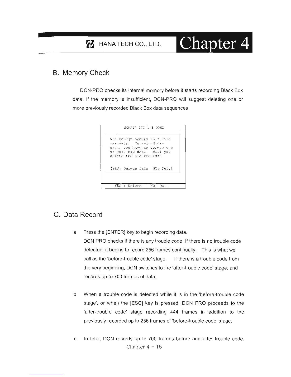
DCN-PRO checks its internal memory befo re it starts recording Black Box
data . If the
memory
is
insufficient, DCN-PRO will suggest deleting one or
more previously recorded Black Box data sequences.
C.
Data Record
SO
NA
el,
1:
1
~
.
8 DOEC
~~:. e~u~g~l
nlem u
ty
t_~ !~C0
;C
;le
w
da~a.
To
record
¡~
e w
a~!·._l~
,
::{D
L:
LA'o/e :
:0 deJe
:.t!
r..JI:~
"!
I
:'~
::".c-
::e
<.."
-1·j
tinta
. ':Ji.i..l
yc~
ci~let.
e
L
hé
oi.
d
t'e~'
(;(ds
?
(Y~3:
Ce l
ete
C
d~a
NU:
Qu:~
)
NO:
QL.:i
L
a Press the [ENTER] key to begin recording data.
DCN PRO checks if there
is
any trouble
codeo
If there
is
no trouble code
detected, it begins to record
256 frames continually. This
is
what we
call
a5
the 'before-trouble eode' 5tage. If there
is
a trouble eode from
the very beginning, DCN switches
to
the 'after-trouble code' stage, and
record s up to 700 frames
of
data.
b When a trouble code is detected while it is
in
the 'before-trouble code
5tage', or when the [ESC] key
is
pressed, DCN PRO proceeds
to the
'after-trouble eode' stage recording 444 frames
in
addition to the
previou51y recorded
up
to 256 frames
of
'before-trouble code' 5tage.
c
In
total,
DeN
record5 up to 700 frames before and after trouble codeo
Ch8pter 4 - 15
Page 65

For
DeN
Scanners
When it reaches 700 frames it automatically stops recordin
g.
BL/\CK
BOX
DI\T/\
02
SENSOR
--------------
624
mV
t17
,¡>
S~l\SOR
----------
- - .-
~16
mr:::J:,¡
/\!R
T
~MP
SENSOR ---
---
- -
3~
' C
TI'S ---
-------------..
- - -
12
¡n'.!
S:SP
MOTOR ----
-------
- -
32
.~\
BI\TTERY
VOLTI\GE --- - - -
--
: 2 .
3V
I
GN!TION SIGNI\L
------
- -
~
FF
COOLANT
TS~:P
SE!,SOR ---
- 92 'C
ENG!NE
RPM --- -
---
- - - - - - 1 10 rpm
IJLE
SWITCH
-------
-----
OK
BEFCRE:
256
/\FTER: 157
DTC
NUM:
2
~SC
: ST
OP
EN':'E
R :
S~LECT
•
d When the frame number reaches 700 or when you press the [ESC) key,
dialog box appears and asks you
to
input the date.
Enter the date and press the [ENTER] key to save the recorded data
to
DCN-PRO memory. Pressing the [ESC) key cancels saving data.
Date format
is
YYYY-MM-DD(Y-year , M-month, D-day), and only
numeric values are available.
BU<:K
BOX
Cl\'1.'1
INPl:-:-
Dr,TA
g
•
MOCEL:
SOIolI\TA
rTI
1.8
DO
EC
DE
VIes:
ENGINE
CONTROL
Di\T
;;:
:
20C3YO
':'
Y03D
oEFORE:
256
I'I\GE
AFT5:R:
2C2
PAGE
Dre
NU~
IBER:
2
t:
~~OVE
SNTER:
SI\
VE
Ese :
CANCE
L
,
~
~
-
'
t'
I J
LE
SWI T
CH
-------
- - -
--
O
~
BEFCRE:
25€-
/\FTE,,:
202
DT
C
N:!M:
2
I
~SC
:
STOP
SNTER : SELSCT
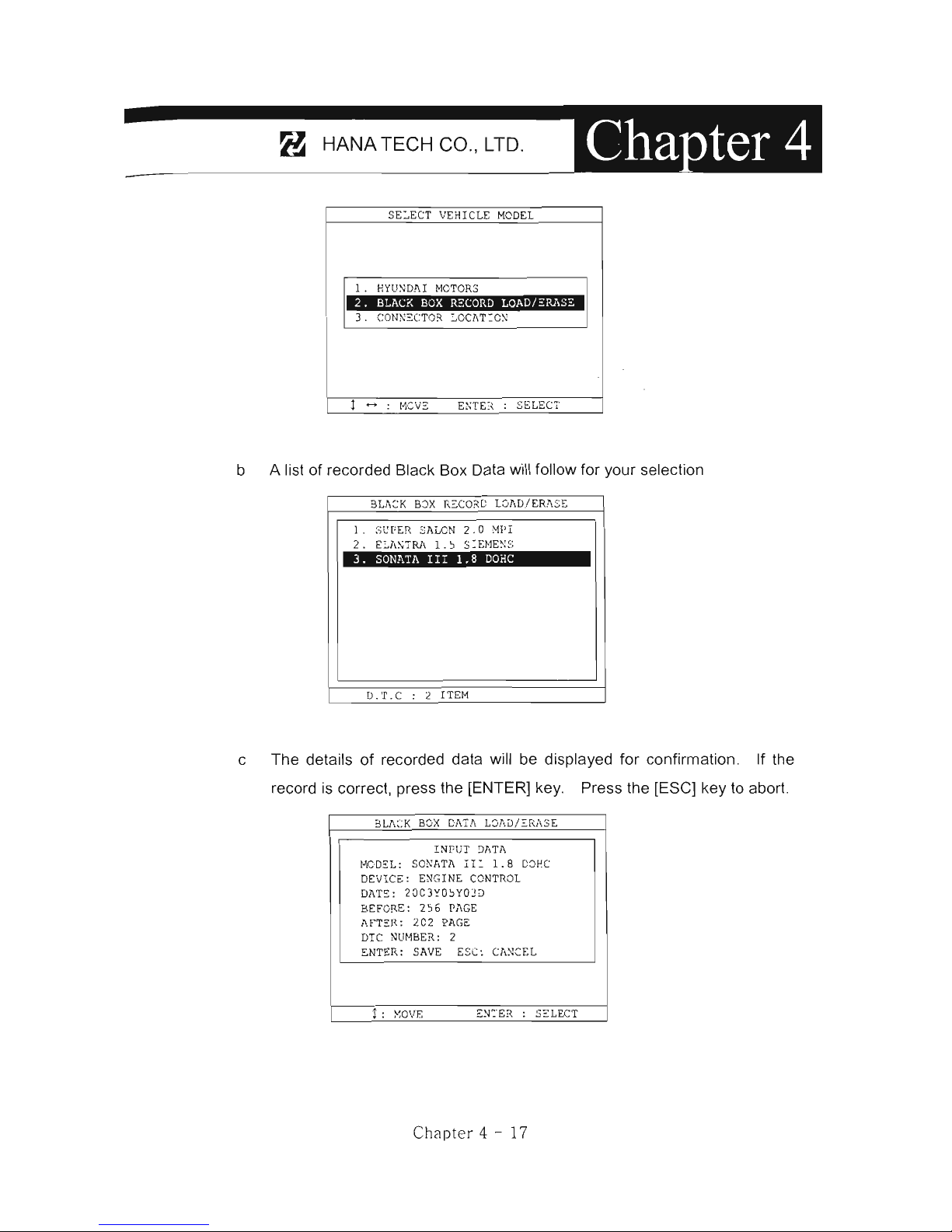
D.
Black Box Data Load
a You can retrieve the saved data by choosing [BLACKBO X RECORD
LOAD / ERASE] from the [Vehicle Model Selection] menu as shown
below:
Chapter
4 - 16
Page 66
:_-----8-
-
H-A-N-A-T-E-C-H-C-O-.,
_LT_D
_.
_----'_
SEL
ECT
VEHICLE
MO
DE:L
l . HYllNDAI
MOTOR
S
2 .
B~ACK
BOX
RECORD
LOAD/~RJ,SZ
E:;TE
7\
SE
LECT
b A list of recorded Black Box Data will follow for your selection
3U\2K
BOX E
CORD
LOl,D/ ER!\
SE
l .
,>U
FER S
ALeN 2.
()
~!PI
2 .
ELM,TRlI
l.
J
S=EJ.1E~:S
3.
SONAéA
IIr
1.8
DOHe
D . T . C 2 1 TEI
"!
c The details
of
recorded data will be displayed for confirmation. If the
record
is
correct, press the [ENTER] key. Press the [ESC] key to
aborto
BL!,~:K
BOX
C1\Tl\
L:::,r,D/!:RlI
SE
INPUT
Dl,TA
HOD"L:
S01>Il,TA
n:
1.8
DOHC
DE:
vrCE:
ENG
I NE CONTR
OL
DlIT
,,:
20C3YO"YOD
BEFORE
:
256
Pl\GE
!\.F"T~R
:
202 P
AGE
DIC
Nm·IBER : 2
ENTER
:
SAVE
Ese:
C
A~KEL
¡ :
}'~OVE
EN:
'ER
:
S"LECT
Chapter
4 - 17
Page 67
For
DeN
Scanners
E.
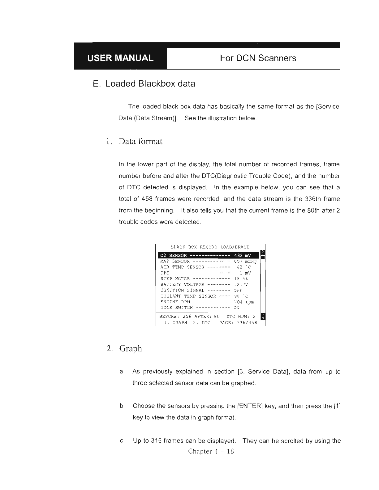
Loaded Blackbox data
The loaded black box data has basically the same format as the [Service
Data (Data Stream)]. See the illustration below.
l.
Data format
In
the lower part
of
the display, the total number
of
recorded frames, frame
number before and after the DTC(Diagnostic Trouble Code), and the number
of
DTC detected
is
displayed.
In
the example below, you can see that a
total
of
458 frames were recorded, and the data stream is the 336th frame
from the beginning.
It
also tells you that the current frame
is
the 80th after 2
trouble codes were detected.
2.
Graph
02
SENS
OR
--------------
432
mV
1111
I'
SENSOR
-------
-----
-
69
¡
m:c.'-l"
A!~
TEMP
SENSOR ---
----
-
~2'C
TrS ---
-----------------
1
mV
S:~P ~C:OR
-------------le.
5\
31,TTE
" Y VDLT
JI.
GE ------- -~ 2 .
IV
I GNi TION SI
GNAL
- -
------D?P
CCOL
AN!
TSXP
SE~SOR
----
98
' C
EN
GINE
R~ M
---
- -
---
- - - --
701
rpm
IJ~E
SW!TCE -----------_.
OX
3EFCR2:
2~6
AFTE",
80 DTe
N:J
H, 2
•
a As previously explained
in
section [3. Service Data], data from
up
to
three selected sensor data can be graphed.
b Choose the sensors by pressing the [ENTER] key , and then press the [1]
key to view the data
in
graph format.
c Up to 316 frames can be displayed. They can be scrolled by using the
Chapt er 4 - 18
Page 68

:_---------~--
.
-H-A-N-A-T-E-CH--C-O-.,-~-D-.--~~
[Al
and
[~l
keys.
d The dotted line indicates from which frame the sensor values are being
displayed. You can move it left and right with the
[~l
and
[~l
keys.
The frame number
is
indicated at the bottom.
02 SENS
OR
.. .......
....
615
mU
nrn
..
",,"'
..........
, • .inrn
••
no
THR
OTILE Posm
ON SENSOR·
4
25
mU
;tt,
I
•
"
ENGINE RPM
.
...
........
827
rpm
I-.A
JJ\""
}vI.""
1
:
LlHE
/ DOr
PAGE
: 187/.317
e To return to the Black Box Data Display , press the [ESC] key.
Chapter 4 - 19
Page 69

For DeN Scanners
V. Connector Location ---------------------------
a The vehicle side
OB02
adapter
is
easy to find as the location
is
quite
regular - under the dash, however, the old vehicle side OLC adapters of
OBO generation 1 are located quite randomly and sometimes
it
is
very
difficult to find.
OCN-PRO has the vehicle side adapter location maps for each car make
to aid the user
in
locating the adapters.
The locations suggested
in
this function are purely from HANA TECH's
experience, therefore, it may contain incorrect information .
It
is
always
highly recommended to refer to the original repair manual published by
the
car
manufacturers for correct information.
SEL
ECT VEHI CLE
~IODEI.
l.
HYU':DAI
MOTOR
S
2 . BLlICK
BOX
RECORD LCII.D! E R1IS:::
3.
CONNECTOR
LOClITION
!
<->
110VE
E~\:ER
SELECT
b Select [CONNECTOR LOCATION] from the vehicle selection menw if the
adapter
is
not found
in
the place where it
is
supposed
to
be .
A drawing indicating the location
of
the vehicle side adapter follows.
In
the right bottom
of
the display, the total number
of
location maps for the
selected car make
is
indicated. The example below is when Hyundai
motors is selected, and it tells there are total 5 maps.
Chap ter 4 - 20
Page 70
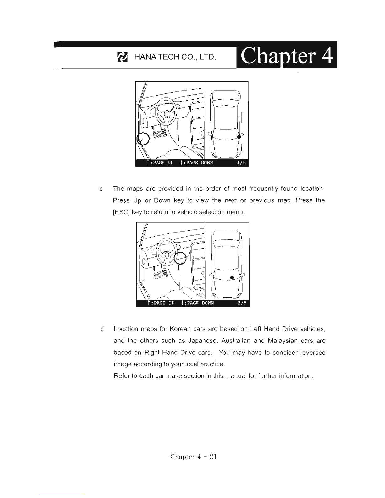
:_-----8-
'
-H-A-N-A-T-E-C-H-C-O-",-LT-D-"---'-
c The maps are provided
in
the order
of
most frequently found location.
Press Up or Oown key to view the next or previous map. Press the
[ESC] key to return
to
vehicle selection menu.
f '
¡'
I
.
__
- - I
d Location maps for Korean cars are based on Left Hand Orive vehicles,
and the others such as Japanese, Australian and Malaysian cars are
based on Right Hand Orive cars.
You
may have
to
consider reversed
image according to your local practice.
Refer
to
each car make section
in
this manual for further information.
Chapler 4 - 21
Page 71

Page 72
GENERle
OBD2
1.
LITERAL DEFINITION
OF
08D2
...... ........
5-1
11.
MORE PRACTICAL NOTES
.............
5-2
A.
Technical meaning of
OB02
5-2
B. Generic and Enhanced
OB02
5-3
111.
DCN-PRO and
08D2
.............
5-5
Page 73

Page 74

:_----~-
.
_H_A_N_A_T_E
C_H_C
0_,_,
L_T_D_, ______
_
Generic
OBD2
1.
Literal definition
of
OBD and OBD2-------
OBO
is
an abbreviation for
On
Board Oiagnostics. OBO-1 is'
in
reference
to
Title
13
California Code 1968 titled "Malfunction and Oiagnostic System for
1988 and Subsequent Model Year Passenger Cars, Light-Outy Trucks, and
Medium-Outy Vehicles with Three-Way Catalyst Systems and Feedback
Contro!." filed on 11-15-85. This required cars sold
in
California to have an
on-board computer processor for on-board self-diagnostics of computer
sensed emission related components, fuel metering device and EGR
(exhaust gas recalculation system). A partial or total malfunction that
exceeded exhaust emission standard would illuminate a
MIL (malfunction
indicator light) and provide on-board identification of the malfunction
location.
To
provide malfunction location information, codes are stored in on-
board computer memory.
To
read codes manufactures use methods, such
as flashing MIL light or various serial data protocols.
OBO-2 is
in
reference to Title
13
California Code 1968.1 titled "Malfunction
and Oiagnostic System Requirements-1994 and Subsequent Model-Year
Passenger Cars, Light-Outy Trucks, and Medium-Outy Vehicles and
Engines. Filed on 8-27-90 to Air Resouce Board (ARB)
This requires a standard electrical connector, open source standardized
diagnostic trouble codes
(OTC), data, and communication protocol with more
specific self-diagnostic on-board monitoring of emission malfunctions.
Chap
ter
5 - 1
Page 75

For DeN Scanners
JI.
More practical notes --------------------------
A.
Technical meaning
of
0802
l.
Standardization
a For the technicians and scan tool engineers,
OB02
has its technical
meaning as bringing the standardized methods
of
vehicle diagnosis
to
the chaotic aftermarket where dozens
of
car make use different
diagnostic adapters and communication protocols
of
their own.
b The 16-pin trapezoid diagnostic adapter and a few
of
most influential
communication protocols including
IS09141-2,
KWP2000, and SAE
J 1850 VPW and PWM form the standard
0802
specifications.
c Trouble codes and Data stream variables were also standardized and
opened to public, so that all the scanners that support aforementioned
standard communication protocols through the 16-pin
OB02
adapter can
always get the same readouts.
2. Purpose
of
OBD and OBD2
a.
OBO and
OB02
are the names of regulation that were legislated
in
USA
for the emission control.
b. On board diagnostics was implemented
to
monitor malfunction or failure
of the emission related parts and components to minimize the possibility
of excessive exhaust gas emission by letting the driver know that the car
has a problem and the technician immediately perceive what
is
the
problem when any trouble
is
detected
in
the emission control system.
And
OB02
became effective later to increase the efficiency of OBO by
standardization.
Chapter 5 - 2
Page 76

:_---
--
8-
'
_H_A_N_A_T_EC_H_C_O_.,_LT
_
D_._---"_
8. Generic
0802
and
Enhanced
0802
1.
Generic
OBD2
a.
OB02
was implemented for the emission control. Therefore, the
standardization
is
limited to powertrain system
that, is
directly related
to
emission control.
It
is
not mandatory for the other systems such
as
ABS
and SRS
b.
Not all the trouble codes and data stream variables are standardized,
also. A list
of
trouble codes and data stream variables that are closely
related to emission control are defined as
OB02
standards, however,
it
al
so allows more codes and variables reserved for car make's own
definition and usage. These standardi zed parts
of
trouble codes and
data stream variables are so called Generic
OB02
. Generic
OB02
application
is
limited to emission related systems and so is the diagnostic
readouts
2. Enhanced
OBD2
a.
Generic
OB02
has limited availability for overall diagnosi
s,
how
ever, an
actual car has a lot more than this. The control systems other than
powertrain are not included
in
the mandatory
OB02
regulations, and
each car make has different trouble code and data stream definitions for
the reserved non-standard fields
of
powertrain system.
b, The scope
of
on board diagnostic system that
OB02
standard features
do not cover
is
called Enhanced
OB02
,
3. Manufacturer
's
OBD
a. Many
of
Non-USA cars
of
1996 model-year or later have an
OB02
16Pin
adapter, however the communication with scanners does not follow
standardized
OB02
protocols.
b. These car makes maintain their own communication features that are not
Chapt
er
5 - 3
Page 77

For
DeN
Scanners
much different from OBO generation 1 but only the appearance
of
diagnostic adapter. This
is
so called MOBO or manufacturer's OBO.
c.
In
DeN-PRO
, MOBO communication
is
supported for all car makes that
are included
in
the coverage list.
Chapter
5 - 4
Page 78

:_---
-8-
'
_H_A_N_A_T_E_C_H_C_O_,,_LT_D_,
__
_
III.
DeN-PRO
and OBD2 ------------------------
A,
Generic
0802
in
DeN-PRO
1,
General OBD2
a You will find General OBD2 category
in
the top
of
the
car
make selection
menu
in
each PCMCIA card
of
OC
N-PRO as shown below,
APPLlCATION
l .
GENERAL
OBD2
V20 1
2.
TOYOTA/LEXUS
V260
3.
HONDA/ACUR!!.
V240
4 .
NISSAN/INFINITI
V2S0
S,
MITSUBISHI
E30
0
6 .
MAZDA
V240
7 .
SUBARU
VIl
O
Ese:
RETURN
TO
ABOVE
b Selecting [1. General OBD2) will be followed by the diagnostic adapter
suggestion. Press the [ENTER) key to proceed .
OBD
11 DIAGNOSTTCS
GENERAL
OBCo
Il DIIIGN
OSTlCS
USE OBD
Il
16PIN
CONNECTOR
PRESS
[ENTEn)
KEY
DE'fERHHJE
cmU"¡~NICl'\TIO:'J
I:'JTERFl\CE
e DCN-PRO then automatically tries to establish communication with the
powertrain control module using standard OBD2 communication
protocols
in
turno
Chapter
5 - 5
Page 79

For
DeN
Scanners
OSD
TI
OTAGNOSTTCS
OSD
11
DIAGNOSTICS
TEST
J18~O
11.6Kbps P
WM
DETERMINE COMWJNICATION INTERFACE DETERMINE
COMMUNICATION
INTERFACE
OSD
TI
DIAGNOSTICS
OBD
JI
DIAGNOSTICS
TEST
T
S09Hl-)
DETERMINE
COMMUNICATION
INTERFACE
DETERMINE
COMMUNICATION
INTERFACE
d When succeeded
in
communicating with the control module with any of
these 4 standard protocols,
DeN
-PRO report s the successful
establishment
of
communication and waits for your comma
nd
to
commence generic OBD2 diagnosis as below:
OBD
JI
DIAGNOSTICS
T
ES
T
J
18~C ~1.6
K bps
?
WM
1 N': 1 A :
.: %1-:
Ol-
iI:- r 1
s~:c:n:é;:
,
Pf{f
:~;::
; : Ul'I'r
::-~
1
Kf
:Y
DETERNINE
COHMUNIC2\TION
INTERFACE
e Available functions for the generic OBD2 system is listed as shown
below:
Chapter 5 - 6
Page 80

:_-
----
8--H
-
A
-
N
-
A-T
-
E
-
C-H-C-O-.,-L-T
-
D.-~---
iI!'
..
OBD
TT
DI AGNOSTICS
l.
SELF
DIAG
RESU~T
(D.T.C)
2 .
C~EAR
OIAG IN FO
RMATION
3 . CC
RRE
NT Ol\TI,
1 . FREEZ E FRI
Ü'1E
DJI.TA
~.
READ
I NE
SSS TES
T
6.
82 SENSO
R TEST
RESU
~ T
<.
..
~10VF:
f
In
case the control module does not respond after trying all OBD2
standard protocols,
DeN-PRO
shows the failure report and check points
as below:
2.
When
to select
OBO
11
DIAGNOSTICS
!!
COrTl",:"ur.icai t.'"Jr . Tc:.";":
'.
Failc
d
!!
~
.
Vcrity
tha~
th
c
~gr:~t~0
~
],5
ON.
2 .
C ~cck
t h c
E~is
fiio
~
labcl c =
V~
~
ic~c ~c
rvi=c i~fo
rma~~o~ ~
~a~
~
he v~t'~í']Q ~~ :~n:
11 cqcipp
eci .
3 .
Check that thc TDol i s
con~~~t
Qd t o
~
h c
v~~i
c~~ ~0~1"0~~:
y.
Do
yo u
wa~
~
:.=y
agai
~
'!
(y(:~
! Ne )
DETERMINE
COMMUNICATION
INTERFACE
You
may
select this General OBD2 when you are sure that the test vehicle
is
OBD2 compliant but not included
in
the vehicle coverage list.
3. E
OBD
a Even though
DeN-PRO
does not include many European cars
in
its
coverage as
of
May, 2003,
it
is
frequently reported that General OBD2 of
DeN-PRO
works well with EOBD vehicles.
Ch
¡:¡pte
r 5 - 7
Page 81

For
DeN
Scanners
b
In
Europe, EOBD has become mandatory from January
1,
2001, and
all
the cars built
in
Europe since then
on
must have been generic OBD2
compliant.
e
You
may select General OBD2 of DCN-PRO for the diagnosis of these
brand new European cars for the powertrain system .
Chapter 5 - 8
Page 82

JAPANESE
CARS
1.
TOYOTA and LEXUS
6-2
11.
HONDA
6
-20
111.
NISSAN
6 -
31
IV. MITSUBISHI
6-39
V.
MAZDA
6-
52
VI. SUBARU
6-
58
Page 83

Page 84

=_-----B--H-A-N-A-T-E-C-H-C-O-,,-LT-D-,----'-
Japanese
Cars
DCN-PRO software package for Japanese cars
is
provided separately
in
a 16MB
flash memory PCMCIA
cardo
A few selected international regions have both
Japanese and Korean car makes features together
in
one PCMCIA card,
The Japanese car PCMCIA card contains a software packag\3 comprising of the
following software groups .
./
TOYOTA / LEXUS USA or TOYOTA / LEXUS NON-USA
./
HONDA
./
NISSAN
./
MITSUBISHI
./
MAZDA
./
SUBARU
./
Generic OBD2
The instructions
in
this manual are based
on
DCN-PRO, when a typical
Non-USA software PCMCIA card
is
inserted.
Loading software
Select
[1
.SCAN] from the initial function selection, and then the list of Japanese car
makes will follow. The detailed menu selection queries will guide you to the correct
diagnostic readouts.
1.
Enhllnced
2. Generic
SCAN
OB02
~
W
4. SCOPE 5.IGNITION
lb
~
3.
MULTIMETER
~
V A
6. CONFIG
Et
Chapter 6 - 1
APPLICATION
.
1.
.GEN¡¡;¡VU.
OB92
2 .
TOW'fA/
LEXUS
J . HONDA! ACURA
4 .
NISSAN/INFINITI
5 .
MITSUBISHI
6 . MJ\.ZDA
7 . SOBARO
-ll2.!H:
-- - ..
V260
V240
V250
EJOO
V240
VllO
Page 85

For DeN Scanners
I. TOYOTA and LEXUS -----------------------
Toyota and Lexus cars share the same scanner communication method s
from a scanner's viewpoint.
DCN-PRO does not separate Toyota and
Le
xus
in
the car make menu
beca use the detailed menu selection procedure and other features are
exactly same for both marques.
You
can select either Toyota or Lexus
in
the
next step.
This chapter covers Toyota cars.
You
can also refer to this section for
diagnosing Lexus cars.
A.
Menu Selection
Toyota software
of
DCN-PRO follows the exactly same menu selection procedur e
as
the manufacturer's original equipment.
l. Select TOYOTA/LEXUS
Select
TOYOTAI
LEXUS from the car make menu.
APPLICATION
l .
GEN
ERAL OBD
2 V20 l
2 .
TOYOTA/LEXUS V260
3 .
HONDA/ ACU
RA
4 . N
ISSAN/
INFINITI
5.
MI TSUBI SHI
6 .
MAZD
A
7 .
SUBI\RU
ESC:
RETURN
TO
ABOVE
V240
V250
E
300
V2
40
VllO
Chap ter 6 - 2
APPLlCATION
l . G
ENERAL
OBD2
V20l
2 . TOYOTA/LEXUS
V260
3 .
HONDA/ACURA
V240
LOAD TOYOTA/LEXUS
V
ER 2.60
2003
/02/
06
ESC :
RETURN
TO
ABOVE
Page 86

:_----8--H
-
A
-
N-A-T-E-C-H
-
C-O-.,-LT
-
D
-.-~
-
2.
Select Model Name
You
can select between Toyota and Lexus at this stage.
Toyota
non-USA
version
is
applicable to all Toyota cars outside North
America.
It
covers 32 different model variants.
SELECT VEHICLE
MODEL
l.
TOYOTA
2.
LEXUS
3.
CONNECTOR
LOCATION
t-
:
MOVE
ENTER: SELECT
3.
Select model code
SELECT VEHICLE
MODEL
l.
4Runner
2.
99L.O
3.
AVALO
N
1.
AVENSIS
5.
CAMRY
6.
CARINA
7.
CE:"ICA
8.
C"NTURY
9.
COROLLA
10.
CORONA
11.
CRESSIDA
12.
CRO\oJN
t-
:MOVE
ENTER: SELECT
You have to select the exact model code
of
the vehicle model (i.e. MCV10,
MCV20, SXV10 a
nd
SXV11
for Camry)
Ea
ch model code represents a significant difference
in
overall system from
other model
codeso
l . MCV10
2.
MCV20
3.
SXV10
1.
SXVll
5.
SXV20
6.
VCV10
t-
:
MOVE
ENTER: SELECT
Chélpter
6 - 3
Page 87

For
DeN Scanners
4.
Select model year and other detailed model specifications
DCN-PRO
may
ask for your selection for a few more steps including model
year, manufacturing plant and the existence
of
02
sensor or immobilizer
system
to
specify the exact vehicle details for precise and accurate result
s.
CAr~RY
1.TMC
PRODUCT
2.0THER
S
1-: MOVE
ENTER: SELECT
1.POWERTRAIN
CONTROL
MODULE
2.ANTI
LOCK
BRAKE
SYSTEM
3 ,CRUI SE CONT
ROL
SYSTEM
4.IMMOBILI
ZER
5
.SRS
AIR
BAG
1-
:MOVE ENTER: SELECT
Chapte r 6 - 4
1.EUROPE
2.0THER
1-: MOVE
ENTER: SELECT
D
1 .
BE
FORE
9708
2
.
9708
-
9808
3.
9808 -9908
4 .
9908 -0009
5.
AFTER
0009
1-: MOVE
ENTER: SELECT
Page 88

:
__
---B-H-A
-N-A-
T_EC_H_C_O_.,_LT
_
D_.
_~e.I_"
B.
Why
so complicated
f
CA~
When selecting
a Camry
l
MCV10
MCV20
1-
with model code MCV20
SXV11
SXV20
VCV10
r
produced by
I TMC Product 1
To
yota Motor Compa ny
Others
I
I
Europe
r-
in Europe
Others
I
Before Aug.97
Aug.
97-Aug.98
AUQ
.98-AUQ.99
I
Aug.
99-Sep.OO
1-
After Sep.
OO
.-
__
i
with Traction
I
With Traction
Control System
W/O Traction
I
I
in the period
Aug 1999
p
2000
f
ro
m
to Se
r
I
Engine ABSITRC CCS IMM SRS
The flow chart shows the menu selection procedure presented above for Camry
as an example.
Many
of
aftermarket scanners have a very simple selection procedure for Toyota
cars by only selecting the diagnostic adapter type. Indonesian Tamaraw and
Le
xus
RX300
are considered same for these scanners.
However, the Toyota OE tool has a very detailed vehicle selection procedure up to
5 or 6 steps . The selection procedure
of
DeN-PRO
is
also designed to provide
reliable and diversified diagnosis at OE toollevel for each specific vehicle.
Chapter 6 - 5
Page 89
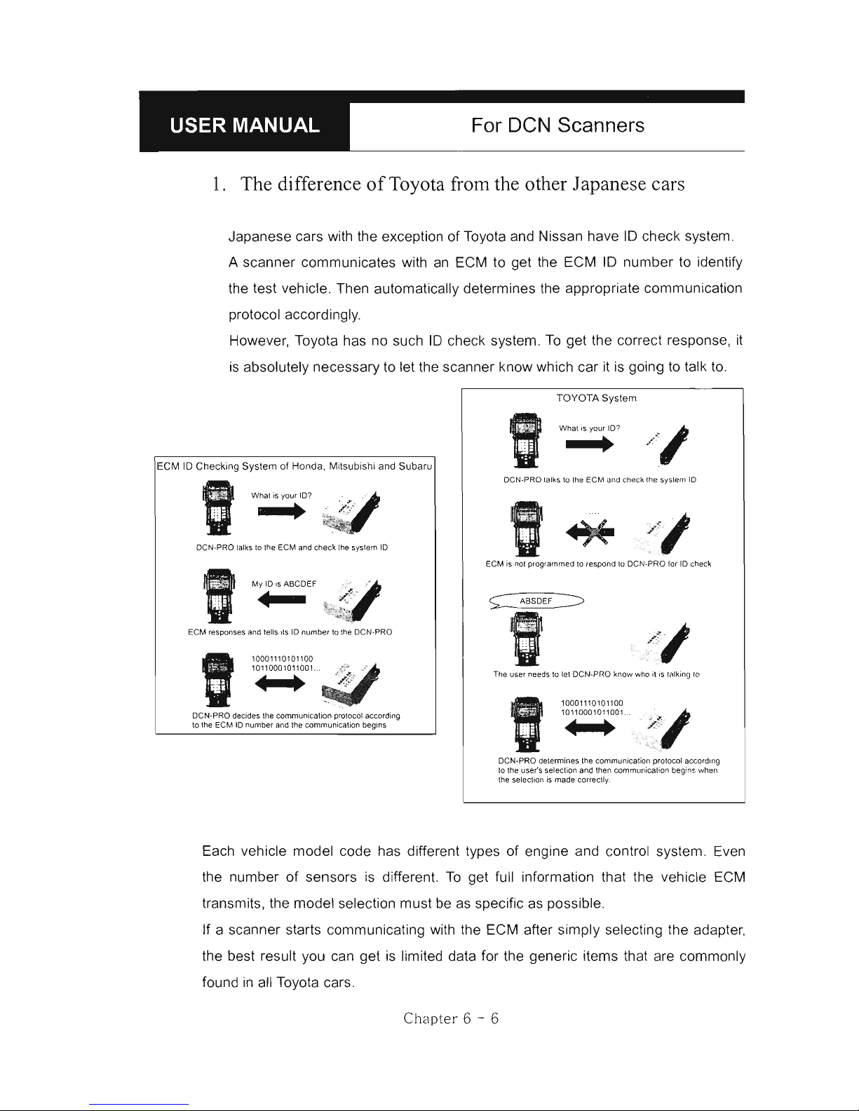
For
DeN
Scanners
l. The difference
of
Toyota from the other J apanese cars
Japanese cars with the exception of Toyota and Nissan have
ID
check system.
A scanner communicates with
an
ECM to get the ECM
ID
number
to
identify
the test vehicle. Then automatically determines the appropriate communication
protocol accordingly.
However, Toyota has no such
ID
check system.
To
get the correct response,
it
is
absolutely necessary to let the scanner know which car
it
is
going
to
talk to.
ECM
ID
Checking System
01 Hon
da. Mitsubis
hi
and Subaru
_
_ h • . i?
Whal is yo
ur
ID? q
,',
, ...
..
~a.
.
~~.
"f:
DC
N.P
RO tat
ks
to
the ECM and check the system
tD
I
~~
"
My tD 's AB
CDE
F
•
ECM responses and teUs lIs ID number lo (he De N-PRO
I
10001110101100
10
11
000 10
11
001... ,
;!
:._
~
. .
,¡¡,
De
N-PRO decides Ihe comrnunicati
on prolocol accordi ng
lo the ECM ID numbe r and the co
mmu
nication
begins
TOYOTA System
"
What is your ID?
/1
..
.
D
eN-PRO talk
s lo Ihe ECM and check Ihe sys lem ID
;//,.
"
ECM is nol programmed
lo
respond lo
DeN-PR
O for ID check
~ ,--:
~
_'",_E
F_
~
The user needs
lO
let De N-PRO know who
il
is lalking lo
"
1000
111
0101100
1011 000101 1001. . /
s1
h
..
n.
II1II
l1li
/..
.:,'
,
.:
..
:
DeN-PRO determines
(h
e communication prolocol accordmg
lo Ih e use
r'
s selection and then
communicat i
on
begins when
the se!ection
is
made co rrect!y.
Each vehicle model code has different types of engine and control system. Even
the number of sensors
is
different.
To
get full information that the vehicle ECM
transmits, the model selection must
be
as specific as possible.
If a scanner starts communicating with the ECM after simply selecting the adapter,
the best result you can get
is
limited data for the generic items that are commonly
found
in
all Toyota cars.
Chapter 6 - 6
Page 90

:_-----B--H-A-N-A-T-E-C-H-C-O-.,
_LT_D_.
_--.J_
2.
How to get the detailed specifications
a Model Code (Chassis number)
Open the engine hood and find the model code stamped into the vehicle
specification tag, attached
to
firewall on the
drivE;lr's
side.
b Model year and manufacturing plant
Model year and manufacturing plant information
is
contained
in
the
Vehicle Identification Number. Refer to the manufacturer's manual
book for the details of VIN translation
c Equipped System
Some models may require you
to
confirm the existence
of
a certain
system like immobilizer or traction control. You can check this from the
warning lamps displayed
in
the dash panel right after turning the ignition
key ON.
3.
[33.0thers]
You will find this category
in
the end
of
the Toyota vehicle model list.
You
may select this when you cannot find the model name
in
the list or when you
do not want
to
make
selections for all the details.
Only the adapter type selection menu will follow, and then DCN -PRO will
begin to communicate with the ECM.
As mentioned aboye, it will work just like an ordinary aftermarket tool does,
and limited data for the common generic items will be available
in
this mode.
Chapt
er 6 - 7
Page 91
For DeN Scanners
4.
Incorrect Adapter
a No match
in
the list
Despite detailed vehicle selection procedure
of
DCN-PRO, you may
encounter a situation where you cannot find the correct vehicle details
in
the list. If you select a similar vehicle model code or other details from
the menu, an incorrect adapter may be suggested.
For
example , when you select AB-CD1 model code while the actual
vehicle
is
AB-CD2 which
is
not included
in
the list, DCN-PRO may ask
you
to
use 17 pin rectangular adapter even though the vehicle has the
17
pin semi-circular adapter.
The communication may fail
in
this case.
You
are recommended to
select [33. Others] to test the car
in
generic mode.
b Multiple adapters
If DCN-PRO suggests to use a diagnostic adapter that is different from
the one that you found
in
the
car,
the suggested adapter may be found
elsewhere in the caro
Some Japanese cars have multiple DLC adapters, and generally each
of them covers different systems.
Refer to the adapter
location maps below, and check the car for the
suggested adapter.
Chapter 6 - 8
Page 92
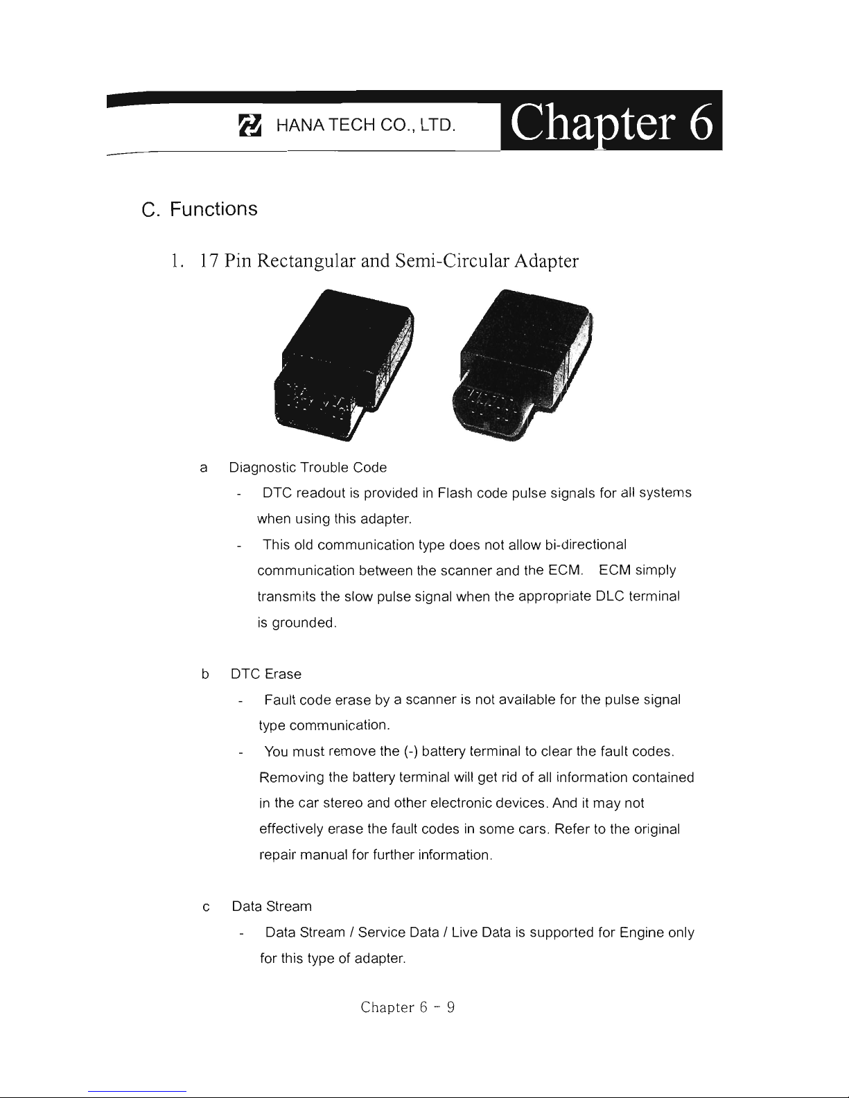
:_-----8-
;
-HA-N-A-T-E-C-H-C-O-.,-L-TD-.-
.-...-J
-
c.
Functions
l.
17
Pin Rectangular and Semi-Circular Adapter
a Diagnostic Trouble Code
DTC readout
is
provided
in
Flash code pulse signals for all systems
when using this adapter.
This old communication type does not allow bi-directional
communication between the scanner and the ECM. ECM simply
transmits the slow pulse signal when the appropriate DLC terminal
is
grounded.
b DTC Erase
Fault code erase by a scanner
is
not available for the pulse signal
type communication.
You
must remove the (-) battery terminal to clear the fault codeso
Removing the battery terminal will get rid of all information contained
in
the car stereo and other electronic devices. And it may not
effectively erase the fault codes
in
some cars. Refer to the original
repair manual for further information.
c Data Stream
Data Stream / Service Data / Live Data
is
supported for Engine only
for this type of adapter.
Chapter 6 - 9
Page 93

For
DeN
Scanners
d Supported systems
Rectangular Adapter: Generally only Engine and SRS systems are
supported with this type
of
adapter.
For the other systems such as ABS, TCS and Cruise Control, only
the flash code manual reading
is
available by counting the relevant
Malfunction Indication Lamp blinking when the adapter is connected
to the vehicle side DLC.
Semi-Circular Adapter: When the vehicle has 17 Pin Semi-Circular
adapter, all systems including Engine and SRS are supported
through this adapter.
2.
16
Pin OBD2 Adapter
a Diagnostic Trouble Code
Fault code read and erase are both
available when using the OBD2 adapter
Neither manual flash code reading nor
battery terminal removal
is
necessary
for code read and erase.
b Data Stream
Service data / Data stream / Live data is available for most systems
Suspension and Cruise control systems
of
a few mode
ls
may
support DTC pulse signal only. Data stream
is
not available for
these exceptional models.
c Actuation test
Actuation test is available for various systems when using this
adapter.
Ch
apte
r 6 - 10
Page 94

:_-----B-H-A-N-A-T-E-C-H-C
-O-
o,-LT-D-o---
D. Diagnostic Adapter Location
The OLC adapter location drawings are purely from the experience
of
Hana Tech
and provided for your reference only.
The drawings are based
on
Right Hand
Orive cars, therefore, you may have
to
consider the mirror image for any Left
Hand Orive carso
You
can view these drawings
on
the oc N-
PRO screen by selecting
[3
.Connector
Location] after selecting [2. Toyota / Lexus]
from the car make list.
17 Pin Rectangular Adapter
16 Pin
0802
Adapter
Ch
apt
er 6 -
11
SELECT VEHICLE
MODEL
lo
TOYOTA
2 .
LEXU
S.
3.
CONNECTo,R
LOCATION
t-
:
MOVE
ENTER: SELECT
17P Semi-Circul ar Adapter
17 Pin Rectangular Adapter
Page 95

For
DeN
Scanners
17 Pin Rectangular Adapter
17 Pin Rectangular Adapter
17 Pin Rectangular Adapter
17 Pin Rectangular Adapter
Chapter 6 - 12
Page 96
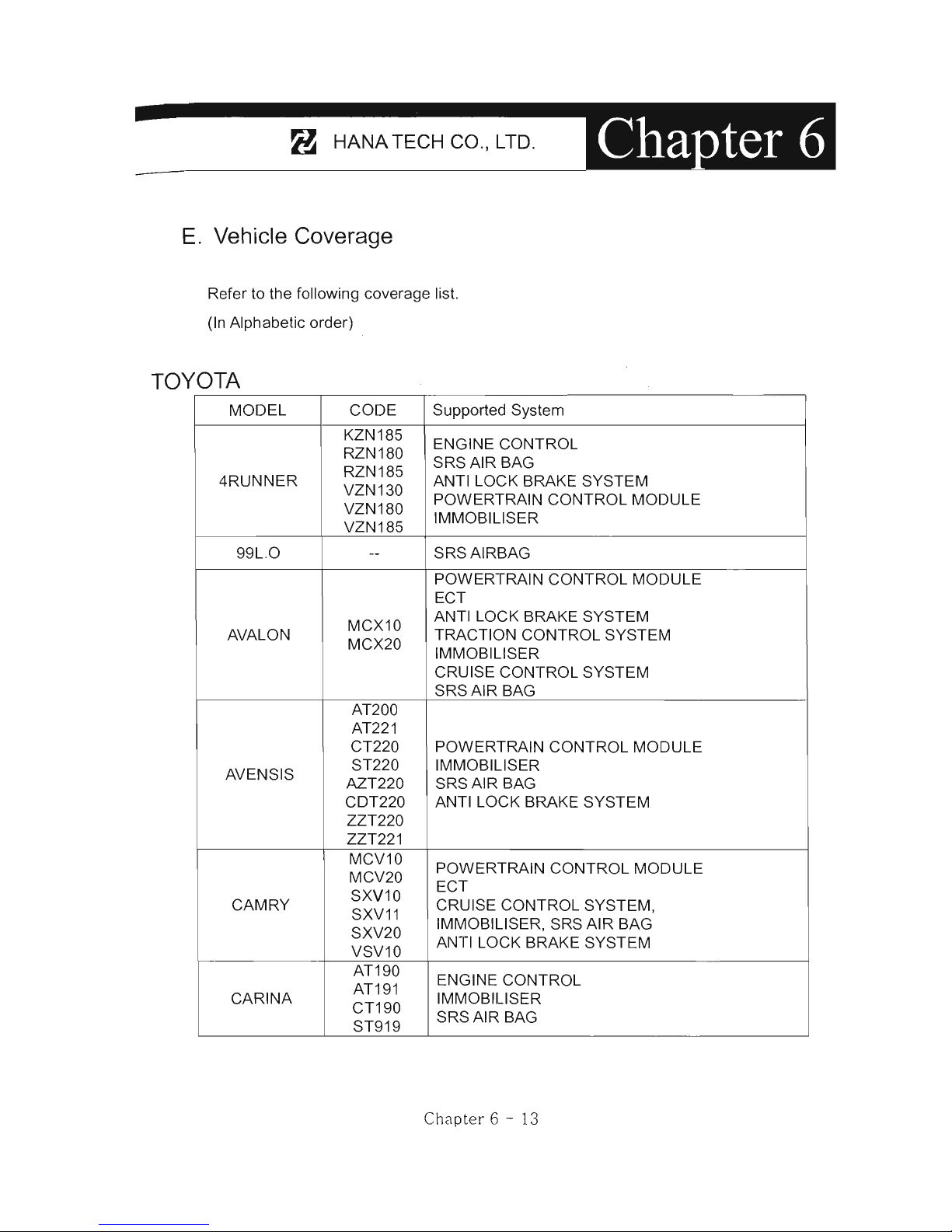
:_---
--
8-
·
_H_AN_A_T_E_C_H_C_O_",
_
LT_D_"_---.J_
E"
Vehicle Coverage
Refer to the following coverage list.
(In Alphabetic order)
TOYOTA
MODEL
CODE Supported System
KZN185
ENGINE CONTROL
RZN180
SRSAIR
BAG
4RUNNER
RZN185
ANTI LOCK BRAKE SYSTEM
VZN130
VZN180
POWERTRAIN CONTROL MODULE
VZN185
IMMOBILlSER
99L .O
--
SRSAIRBAG
POWERTRAIN
CONTROL
MODULE
ECT
MCX10
ANTI LOCK BRAKE SYSTEM
AVALON
MCX20
TRACTION
CONTROL
SYSTEM
IMMOBILlSER
CRUISE CONTROL SYSTEM
SRSAIR
BAG
AT200
AT221
CT220
POWERTRAIN CONTROL MODULE
AVENSIS
ST220 IMMOBILlSER
AZT220
SRSAIR
BAG
CDT220 ANTI LOCK BRAKE SYSTEM
ZZT220
ZZT221
MCV10
POWERTRAIN
CONTROL
MODULE
MCV20
SXV10
ECT
CAMRY
SXV11
CRUISE CONTROL SYSTEM,
SXV20
IMMOBILlSER, SRS AIR BAG
VSV10
ANTI LOCK BRAKE SYSTEM
AT190
ENGINE CONTROL
AT191
CARINA
CT190
IMMOBILlSER
ST919
SRSAIR
BAG
Chapt
er 6 - 13
Page 97

For
DeN Scanners
AT180
AT200
ST182
ST184 POWERTRAIN CONTROL MODULE ,
CELlCA
ST185
IMMOBILlSER
ST202
SRSAIR
BAG
ST204 ANTI LOCK BRAKE SYSTEM
ST205
ZZT230
ZZT231
ENGINE CONTROL
AIR SUSPENSION,
CENTURY GZG50 CRUISE CONTROL SYSTEM
IMMOBILlSER
SRS AIR BAG, BODY CONTROL
BB50
COASTER
BB58
POWERTRAIN CONTROL
RZB40 ANTI LOCK BRAKE SYSTEM
RZB50
LF6X ,8X
ENGINE CONTROL
CONDOR RZF80
IMMOBILlSER
RXF85
AE100
AE101
AE102
AE103
AE110
AE111
AE112
AE115
AE92 POWERTRAIN CONTROL MODULE
CE110
IMMOBILlSER
COROLLA EE101
SRSAIR
BAG
EE104 ANTI LOCK BRAKE SYSTEM
EE111
EMPS
CDE110
NZE120
NZE121
WZE110
ZZE111
ZZE112
ZZE121
ZZE122
Chapter
6 - 14
Page 98

:_-----8-H-A-N-A-T-E-C-H-C-O-",-LT-D-"-------
iII'- •
AT190
AT210
AT220 POWERTRAIN CONTROL MODULE
CORONA
CT220 ANTI LOCK BRAKE SYSTEM
ST171
IMMOBILlSER
ST191 SRS AIR BAG
ST210
ST220
ENGINE CONTROL
CRESSIDA
ANTI LOCK BRAKE SYSTEM
--
CRUISE CONTROL SYSTEM
ECT
POWERTRAIN CONTROL MODULE
CRUISE CONTROL SYSTEM
GS151 ANTI LOCK BRAKE SYSTEM
CROWN
JZS1 33 VSC, ECT, SRS AIR BAG
JZS155 AIR CONDITIONING SYSTEM
JZS17 5
IMMOBILlSER
BODY1/2/3, D/P DOOR,
SLlDE
ROOF, TILT &
TELESCO , METER, COMBINATION SW ITCH
RZU100
BU213
BU223
XZU300
POWERTRAIN CONTROL MODULE
DYNA
XZ
U320
ANTI LOCK BRAKE SYSTEM
XZU330
XZ U340
XZU342
XZ
U4XX
Ch
Clpt
er 6 - 15
Page 99
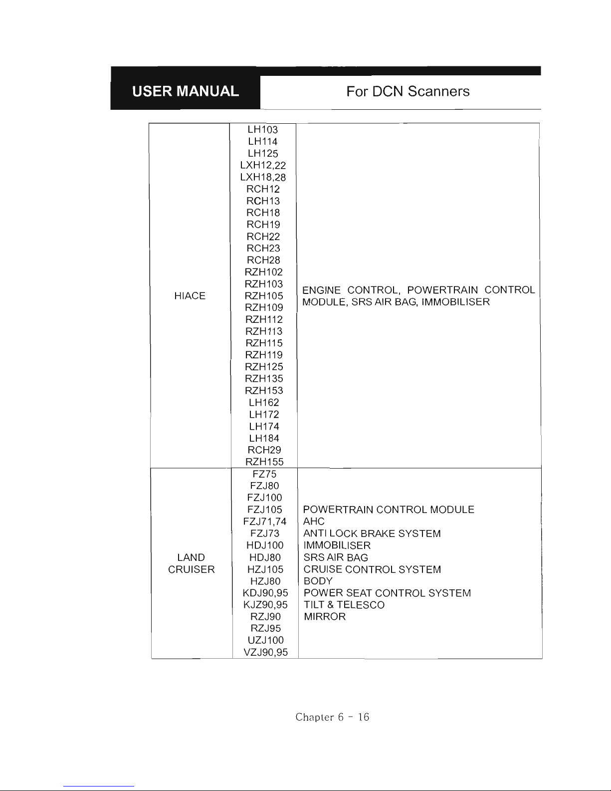
For
DeN
Scanners
LH103
LH114
LH125
LXH12,22
LXH18,28
RCH12
RCH13
RCH18
RCH19
RCH22
RCH23
RCH28
RZH102
RZH103
ENGINE CONTROL, POWERTRAIN CONTROL
HIACE RZH105
RZH109
MODULE, SRS AIR BAG, IMMOBILlSER
RZH112
RZH113
RZH115
RZH119
RZH125
RZH135
RZH153
LH162
LH172
LH174
LH184
RCH29
RZH155
FZ75
FZJ80
FZJ100
FZJ105
POWERTRAIN
CONTROL
MODULE
FZJ71 ,74 AHC
FZJ73
ANTI LOCK BRAKE SYSTEM
HDJ100
IMMOBILlSER
LAND HDJ80
SRSAIR
BAG
CRUISER HZJ105
CRUISE CONTROL SYSTEM
HZJ80
BODY
KDJ90,95
POWER
SEAT CONTROL SYSTEM
KJZ90,95
TILT
& TELESCO
RZJ90 MIRROR
RZJ95
UZJ100
VZJ90,95
Chapter
6 - 16
Page 100

:_------
---
8---H-AN
-
A-T-E-C-H-C-O-
.,
-~-D-.---~
LN14X
LN15X
LN16X
LN17X
LN19X
RN106
RN110
RN85
RXN142
RZN144
POWERTRAIN CONTROL MOQULE
HILUX
RZN149
IMMOBILlSER
RZN147
SRSAIR
BAG
RZN1 48
RZN154
RZN168
RZN169
RZN173
RZN174
RZN193
RZN194
KZN165
KZN190
KF72
KIJANG
KF8 2
ENGINE CONTROL
RZ
F71
RZ
F81
CR42
POWERTRAIN CONTROL MODULE
LlTEACE
KR42
SRSAIR
BAG
SR40
IMMOBILlSER
YR22,29
POWERTRAIN CONTROL MODULE
SRSAIR
BAG
MR2
SW
20 IMMOBILlSER
ZZW30
ANTI LOCK BRAKE SYSTEM
EHPS
SEQUENTIAL MT
ENGINE CONTROL
PASEO
EL54
SRSAIR
BAG
IMMOBILlSER
CXM10
POWERTRAIN CONTROL
PICNIC IMMOBILlSER
SXM10
SRSAIR
BAG
TCR10,11
POWERTRAIN CONTROL MODULE
SRSAIR
BAG
PREVIA
TCR20 ,
21
IMMOBILlSER
ACR
30
ANTI LOCK BRAKE SYSTEM
CLR30
CRUISE CONTROL MODULE
C
h;:¡pt
er 6 - 17
 Loading...