


Hamworthy Trigon
ST1 Solar Pump Station
Installation, Commissioning,
Operation & Service Instructions
IMPORTANT NOTE
THESE INSTRUCTIONS MUST BE READ
AND UNDERSTOOD BEFORE INSTALLING,
COMMISSIONING, OPERATING OR
SERVICING EQUIPMENT

Customer After Sales Services
Telephone: 01202 662555 E-mail: service@hamworthy-heating.com Fax: 01202 662522
Technical Enquiries
To supplement the detailed technical brochures, technical advice on the application and use of products in the Hamworthy
Heating range is available from our technical team in Poole and our accredited agents.
Site Assembly
Hamworthy offer a service of site assembly for many of our products where plant room access is restricted. Using our trained staff
we offer a higher quality of build and assurance of a boiler built and tested by the manufacturer.
Commissioning
Commissioning of equipment by our own engineers, accredited agents or specialist sub-contractors will ensure the equipment is
operating safely and efciently.
Service Contracts
Regular routine servicing of equipment by Hamworthy service engineers inspects the safety and integrity of the plant, reducing the
risk of failure and improving performance and efciency. Service contracts enable you to plan and budget more efciently.
Breakdown service, repair, replacement
Hamworthy provide a rapid response breakdown, repair or replacement service through head ofce at Poole and accredited
agents throughout the UK.
Spare Parts
We offer a comprehensive range of spare parts, providing replacement parts for both current and discontinued products. Delivery
options are available to suit you. Please refer to our website for more details.

Hamworthy Trigon
ST1 Solar Pump Station
Installation, Commissioning,
Operation & Service Instructions
NOTE: THESE INSTRUCTIONS MUST BE READ AND UNDERSTOOD BEFORE
INSTALLING, COMMISSIONING, OPERATING OR SERVICING THIS EQUIPMENT.
THE TRIGON ST1 SOLAR PUMP STATION COMPLIES WITH ALL RELEVANT EUROPEAN DIRECTIVES.
PUBLICATION NO. 500001281
ISSUE ‘A’
JUNE 2013
HAMWORTHY HEATING LTD
Page
TRIGON SOLAR THERMAL
i
1
500001281/A

HAMWORTHY TRIGON
INSTALLATION AND
OPERATION MANUAL
SOLAR PUMP STATION ST1
Customer Service Centre
Hamworthy Heating Limited
Fleets Corner, Poole,
Dorset BH17 0HH l
0DNO0201 Installation-Operation ST1 Solar Pump Station 1

1 General information
Item no. 0DNO0201
Translation of the original instructions
We reserve the right to make technical changes without notice!
Printed in Germany – Copyright by Hamworthy
2 Installation-Operation ST1 Solar Pump Station 0DNO0201

1 General information
Contents
1
General information ......................................................................................................... 4
1.1 About these instructions ............................................................................................... 4
1.2 About this product ........................................................................................................ 4
1.3 Designated use ............................................................................................................ 5
Safety instructions ........................................................................................................... 6
2
3
Assembly and installation [installer] .................................................................................. 8
4
Commissioning [installer] ............................................................................................... 11
4.1 Flushing and filling the solar circuit ............................................................................. 12
4.2 Preparations before flushing ....................................................................................... 14
4.3 Flushing and filling ..................................................................................................... 14
4.4 Setting the solar installation (only for standard solar pumps) ...................................... 17
Maintenance [installer] ................................................................................................... 18
5
5.1 Draining the solar installation ..................................................................................... 18
5.2 Disassembly ............................................................................................................... 18
Spare parts [installer] ..................................................................................................... 19
6
6.1 ST1 Solar Pump Station ............................................................................................. 19
Controller extension .............................................................................................................. 20
20
Technical data
7
..............................................................................................................
.
7.1 Pressure drop characteristics ST1 Solar Pump Station .............................................. 21
Function check valves [installer] ..................................................................................... 22
8
9
Commissioning report ....................................................................................................
2
4
0DNO0201 Installation-Operation ST1 Solar Pump Station 3

1 General information
1 General information
Carefully read these instructions before installation and commissioning. Save these
instructions in the vicinity of the installation for future reference.
.1 About these instructions
1
These instructions describe the installation, commissioning, function and operation of the
TRIGON ST1 Solar Pump Station. The chapters called [installer] are intended for installers only.
For other components of the solar thermal system such as collectors, tanks, expansion vessels
and controllers, please refer to the instructions for that component.
.2 About this product
1
The station is a premounted fitting group checked for leakage used to circulate the solar fluid in
the solar circuit. It is mounted on a wall bracket and fixed with clips. The solar station is
optionally equipped with a controller. It contains important fittings and safety devices for the
operation of the installation:
• Ball valves in the flow line (1.1) and return line (5.1)
• Check valves in the flow (1.1) and return ball valves (5.1)
• Thermometers in the flow (5.2) and
return line (1.2)
• Pressure gauge to display the installation pressure (1.6)
• Flowmeter to display the flow rate (3.3)
• Ball valve to reduce the flow rate (3.1)
• Solar pressure relief valve (1.3)
• De-aerator to easily vent the solar circuit (4.2)
• Drain (3.2) and fill valves (1.4) with hose connectors
4 Installation-Operation ST1 Solar Pump Station 0DNO0201

1 General information
1.3 Designated use
The solar station may only be used as a pump station in the solar circuit taking into
consideration the technical limit values indicated in these instructions. Due to its design the
station must be mounted and operated as described in these instructions!
Improper usage excludes any liability claims.
Flow
1.3
5.2
4.2
Return
1.4
5.1 1.1
1.6
1.5
1.2
2
3.2
3.1
4.1
3.3
3.4
When the sun shines, the collector can become very hot. The solar fluid
in the circuit can heat up to more than 100 °C.
Only flush and fill the solar circuit when the collector temperatures are
below 70 °C.
0DNO0201 Installation-Operation ST1 Solar Pump Station 5

2 Safety instructions
2 Safety instructions
The installation and commissioning as well as the connection of electrical components require
technical knowledge commensurate with a recognised vocational qualification as a fitter for
plumbing, heating and air conditioning technology, or a profession requiring a comparable level
of knowledge [installer]. The following must be observed during installation and commissioning:
• relevant local and national regulations
• accident prevention regulations of the professional association
• instructions and safety
• use appropriate personal and protective equipment eg safety glasses, gloves, etc...
instructions mentioned in this manual
WARNING
Danger of scalding due to vapour escape!
With pressure relief valves there is risk of scalding due to vapour escape. During
installation, check the local conditions and if a discharge line must be connected
to the safety group.
Observe the instructions regarding the pressure relief valve.
The pressures calculated by the installation planner for the expansion
vessel and the operating pressure of the installation must be set.
CAUTION
Risk of burns!
The valves, fittings and the pump may heat up to more than 100 °C during
operation.
The shell must remain closed during operation.
6 Installation-Operation ST1 Solar Pump Station 0DNO0201

2 Safety instructions
CAUTION
Personal injury and damage to property due to overpressure!
By closing the two ball valves in the primary circuit you isolate the pressure relief
valve from the heat exchanger. A rise in temperature in the storage tank will
cause high pressures and could result in personal injury or damage to property!
Only close the ball valves for service and maintenance.
NOTICE
Material damage due to mineral oils!
Mineral oil products cause lasting damage to seals made of EPDM, whereby the sealant
properties are lost. We do not assume liability nor provide warranty for damage to property
resulting from sealants damaged in this way.
It is imperative to avoid that EPDM gets in contact with substances containing mineral
oils.
Use a lubricant based on silicone or polyalkylene and free of mineral oils such as
Unisilikon L250L and Syntheso Glep 1 of the Klüber company or a silicone spray.
0DNO0201 Installation-Operation ST1 Solar Pump Station 7

3 Assembly and installation [installer]
3 Assembly and installation [installer]
NOTICE
Material damage due to high temperatures!
Install the at a sufficient distance from the collector field, since the solar fluid may
be very hot near the collector. It may be necessary to install an intermediate tank in order to
protect the expansion vessel.
pump station
1. Remove the station from the packaging.
2. Remove the insulating front shell.
3. Copy the mounting holes of the solar station besides
the thermometers to the mounting surface.
4. Drill the holes and mount the solar station to the wall
with the enclosed wall plugs and screws.
8 Installation-Operation ST1 Solar Pump Station 0DNO0201

3 Assembly and installation [installer]
5. Connect the solar station to the installation:
5.1 flow from the collector field
1.1 return to the collector field
4.1 flow to the storage tank
3.4 return from the storage tank
6. Connect the pipe for the expansion vessel below the
pressure gauge [1.5] and fix the bracket for the
expansion vessel.
7. Pressurise the expansion vessel as specified by the
manufacturer and connect the expansion vessel.
Observe the separate instructions regarding the
expansion vessel!
8. Check all screw connections and tighten them if
necessary.
Optionally available!
0DNO0201 Installation-Operation ST1 Solar Pump Station 9

3 Assembly and installation [installer]
WARNING
Risk to life and limb due to electric shock!
Prior to commencing electrical work on the controller, disconnect the mains
plug from the mains
Only after completing all installation work, flushing and filling, plug the
mains plug of the controller into a socket! This avoids an unintentional start
of the motors.
9. Connect the pump and the sensors to the controller.
The assembly of the solar station is completed and you
can put the station into operation.
10 Installation-Operation ST1 Solar Pump Station 0DNO0201

4 Commissioning [installer]
4 Commissioning [installer]
Observe the following safety instructions regarding the commissioning of the station:
WARNING
Risk of burning and scalding!
The fittings can heat up to more than 100 °C. Therefore, do not clean or fill the
system with the collectors heated (intense sunshine). Please note that hot solar
fluid can leak from the pressure relief valves in case of too high system pressure!
During venting the solar fluid may escape as vapour and cause scalding!
Only flush and fill the installation when the collector temperatures are
below 70 °C when wearing appropriate personal and protective equipment.
NOTICE
Risk of frost!
It often happens that the solar thermal system cannot be completely drained after flushing.
Thus, there is risk of frost damage when flushing with water. Therefore, do only use the solar
fluid used later to flush and fill the solar installation.
Use a water and propylene glycol mixture with max. 40% of propylene glycol as a solar
fluid.
NOTICE
Note regarding the commissioning sequence
When putting the system into operation, first fill the heating circuit and then the solar circuit.
This guarantees that heat that may possibly be absorbed by the collectors during
commissioning can be dissipated.
NOTICE
Note regarding the expansion vessel
To prevent that the dirt particles in the solar thermal system are flushed into the expansion
vessel, some manufacturers recommend to disconnect the expansion vessel from the solar
circuit before flushing and filling. Please observe the instructions of the manufacturer.
0DNO0201 Installation-Operation ST1 Solar Pump Station 11
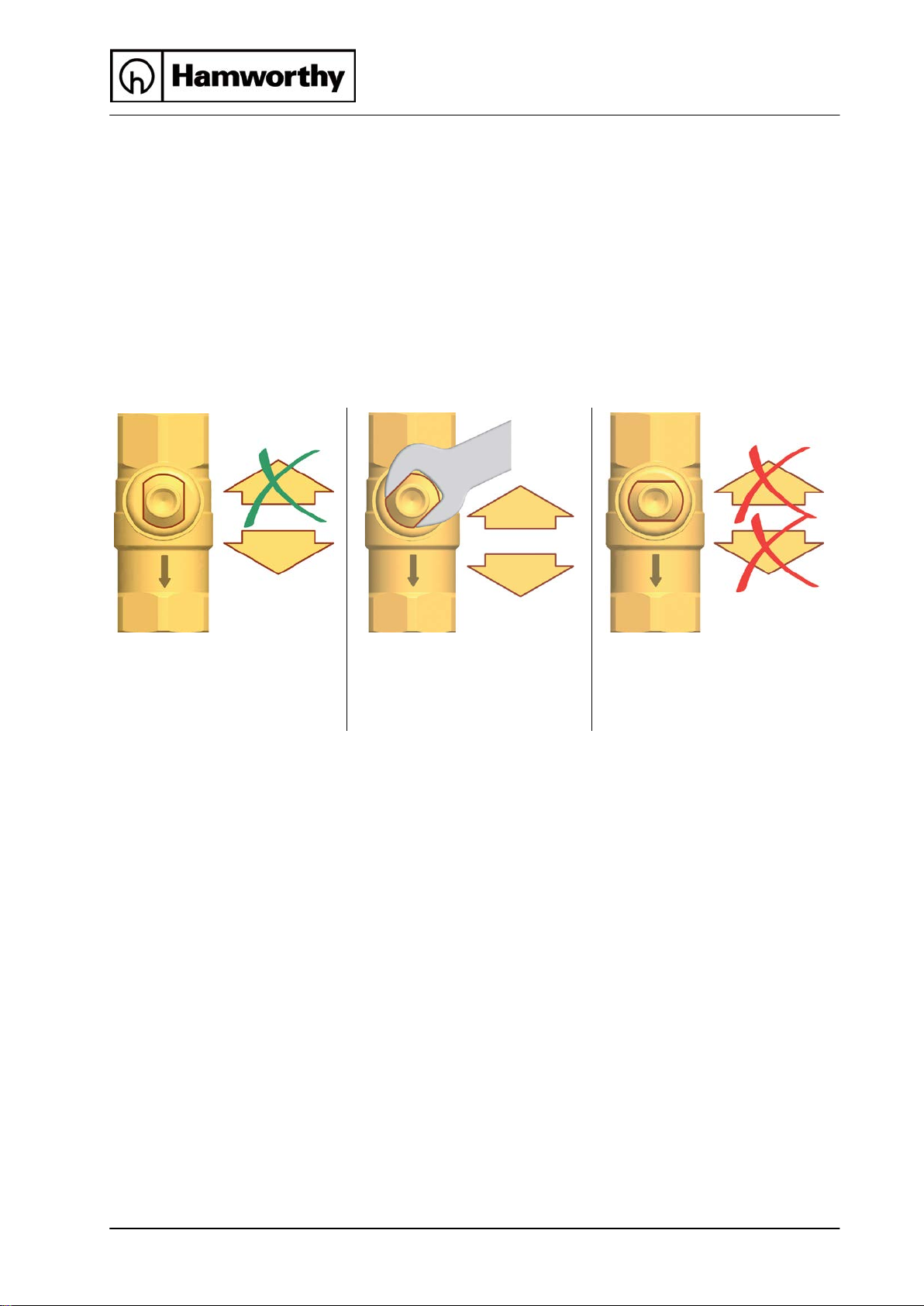
4 Commissioning [installer]
flow only in flow direction.
flow in both directions.
no flow.
4.1 Flushing and filling the solar circuit
The fill and drain valves required to flush and fill are integrated in the solar station.
To flush the dirt particles out of the installation, only use flush and fill stations with fine filters.
Ball valve with integrated flow check valve (1.2 and 5.2)
(normal flow direction in the figure below: downwards)
0° 45° 90°
Check valve is operating,
Check valve is not operating,
Ball valve closed,
12 Installation-Operation ST1 Solar Pump Station 0DNO0201

4 Commissioning [installer]
De-aerator
The de-aerator with manual vent valve is used to vent the solar
installation. To ensure perfect deaeration of the solar circuit, the flow
velocity must be at least 0.3 m/s in the flow line.
Pipe diameter [mm] Flow rate at 0.3 m/s
∅ outside ∅ inside l/h l/min
15 13 ~ 143
~ 2.4
18 16 ~ 217 ~ 3.6
22 20 ~ 339 ~ 5.7
The air liberated from the solar fluid is collected in the upper part of the de-aerator and can be
released at the vent plug [4.2].
WARNING
Danger of scalding due to vapour escape!
The escaping fluid can have a temperature of more than 100 °C and cause
scalding.
Carefully open the vent plug and close it again, as soon as medium
escapes.
enting the solar installation after commissioning
V
At the beginning, vent the solar installation daily and then weekly or monthly,
depending on the vented air quantity. Thus, an optimum operation of the solar
installation is ensured. Check the system pressure after venting and increase it to the
specified operating pressure, if necessary.
0DNO0201 Installation-Operation ST1 Solar Pump Station 13

4 Commissioning [installer]
4.2 Preparations before flushing
4.3 Flushing and filling
The solar circuit is flushed in the direction of
flow.
1. Disconnect the expansion vessel from the
solar installation. Please observe the
instructions of the manufacturer.
2. Turn the check valve in the flow ball
valve [5.2] to operating position
(0°, see page 12).
3. Close the return ball valve [1.2]
(90°, see page 12).
4. The ball valve [3.1] must be open.
5. Connect the filling pump to the solar
station:
- Pressure hose to the fill valve [1.4]
- Flush hose to the drain valve [3.2]
1. Open the fill and drain valves [1.4|3.2].
2. Put the flush and fill station into operation
and flush the installation until clear solar
fluid exits.
Vent the solar installation several times at
the vent plug of the de-aerator [4.2] until
the solar fluid exits without bubbles
(see page 13).
14 Installation-Operation ST1 Solar Pump Station 0DNO0201

4 Commissioning [installer]
3. To vent the pump stroke, slowly open the
return ball valve [1.2] (0°, see page 12).
4. Close the drain valve [3.2] with the filling
pump running and increase the system
pressure to max. 5 bars. The system
pressure can be read on the pressure
gauge. Close the fill valve [1.4] and switch
off the pump of the flush and fill station.
Consider the pressure relief valve (6 bars)!
5. Check the pressure gauge to see whether
the system pressure reduces and eliminate
leaks where necessary.
6. Reduce the pressure at the drain
valve [3.2] to the operating pressure.
7. Connect the expansion vessel to the solar
circuit and set the operating pressure of the
solar system by means of the flush and fill
station (for the required operating pressure,
see instructions of the expansion vessel).
8. Close the fill and drain valves [1.4|3.2].
9. Turn the check valve in the return ball
valve [1.2] to operating position
(0°, see page 12).
0DNO0201 Installation-Operation ST1 Solar Pump Station 15

4 Commissioning [installer]
WARNING
Risk to life and limb due to electric shock!
Check if the sensors and the pumps are properly connected to the
controller and if the controller housing is closed. Only then should the
mains plug of the controller be plugged into a socket.
10. Connect the optional controller to the mains and
set the solar circuit pump in the manual mode to
Max. according to the controller instructions. Let
the solar circuit pump run at maximum rotation
speed for at least 15 minutes.
Meanwhile vent the solar installation several times
at the vent plug of the de-aerator until the solar
fluid exits without bubbles (see page 12).
If necessary, increase the system pressure to the
11. Remove the hoses of the flush and fill station and
screw the sealing caps onto the fill and drain
valves.
The sealing caps only serve to protect the valves
against dirt. They are not designed to take up high
system pressures. The ball valves must be closed.
12. Only for standard solar pumps:
Continue at point "4.4 Setting the solar installation"
only for PWM pumps:
Mount the insulating front shell. Switch the
controll
er to automatic mode (see controller
instructions).
16 Installation-Operation ST1 Solar Pump Station 0DNO0201
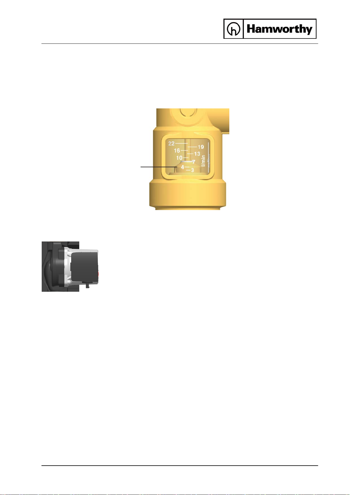
4 Commissioning [installer]
Scale DN 20:
Round edge
Example:
about 4 l/min
Three speed solar pump
4.4 Setting the solar installation (only for standard solar pumps)
Observe the specifications of the collector manufacturer for the correct adjustment of the
flow rate.
3 – 22 l/min
Reading edge =
of the float
Optional controllers:
1. Set the pump P1 to Max. in the manual mode of
the controller to set the maximum flow rate. The
controller sets the corresponding rotation speed.
If necessary, the flow rate can be adjusted at the
ball valve [3.1].
2. Mount the insulating front shell to the station.
3. Switch the controller to automatic mode
DeltaSol BS/2 (Standard controller)
(see controller instructions).
DelatSol M (Advanced controller)
The commissioning of the solar installation is now complete. Please fill in completely the
commissioning report on page 25.
0DNO0201 Installation-Operation ST1 Solar Pump Station 17

5 Maintenance [installer]
5 Maintenance [installer]
5.1 Draining the solar installation
1. Switch off the controller and make sure that a
restart is not possible.
2. Open the check valves in the flow and return ball
valve [5.2|1.2], by turning them to a 45° position
(45°, see page 12).
3. Connect a heat-resistant hose to the lowest drain
valve of the solar installation (or to drain valve [3.2]).
Make sure that the solar fluid is collected in a heatresistant container.
WARNING
Danger of scalding due to hot solar fluid!
The escaping fluid may be very hot.
Place and fix the heat-resistant collecting container so that people
standing nearby are not endangered when the solar installation is being
emptied.
4. Open the drain valve at the lowest point of the solar thermal system.
5. To accelerate draining of the solar circuit, you can open the bleeding device,
if present, at the highest point of the solar thermal system.
6. Dispose of the solar fluid observing the local regulations.
.2 Disassembly
5
1. Drain the solar thermal installation as described above.
2. Disconnect the pipe joints with the solar thermal system.
3. To remove the solar station from the mounting plate, pull
the clips to the side using a screwdriver.
4. Pull out the station towards the front.
18 Installation-Operation ST1 Solar Pump Station 0DNO0201
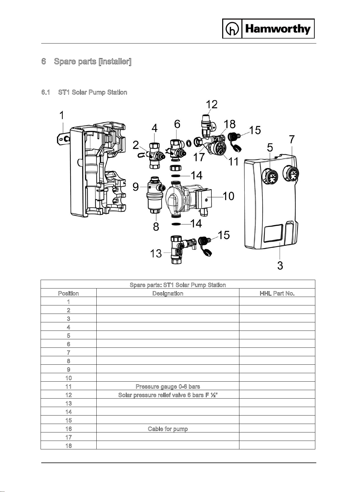
6 Spare parts [installer]
Spare parts: ST1 Solar Pump Station
Position
Designation
HHL Part No.
1
Wall bracket
073336
2
Fixation clip (x 5)
073071
3
Front and back insulating shell made of EPP
073786
4
Ball valve with check valve, return from collector
073085
5
Thermometer, return from collector (red)
073787
6
Ball valve with check valve, flow towards collector
073072
7
Thermometer, flow towards collector (blue)
073788
8
De-aerator
073344
9
Vent plug
073789
10
Pump Wilo Star-ST 15/7 ECO-3
073068
11
Pressure gauge 0-6 bars
073790
12
Solar pressure relief valve 6 bars F ½"
073404
13
Flowmeter 3-22 l/min ST1
073792
14
Sealing set ST1
073347
15
Drain connection
073346
16
Cable for pump
073348
17
Counter cross
18
Fill and drain valve
6 Spare parts [installer]
In case of a complaint, please send us the completely filled commissioning report on page 25.
.1 ST1 Solar Pump Station
6
n.c.
n.c.
0DNO0201 Installation-Operation ST1 Solar Pump Station 19

7 Technical data
Dimensions ST1 Solar Pump Station
7 Technical data
Height (with controller extension)
560 mm
Height (without controller extension) 383 mm
Width (with insulation) 334 mm
Depth (with insulation) 150 mm
Centre distance flow/return 100 mm
Pipe connections ¾" internal thread
Connection for expansion vessel ¾" external thread, flat sealing
Outlet pressure relief valve ¾" internal thread
Operating data
Max. admissible pressure PN 10
Max. operating temperature 120 °C
Max. short-time temperature 160 °C, < 15 minutes
Max. propylene glycol content 40 %
Equipment
Pressure relief valve 6 bars
Pressure gauge 0 – 6 bars
Check valves 2 x 200 mm wc, can be opened
Flowmeter 3-22 l/min
Material
Valves and fittings Brass
Gaskets EPDM
Check valves Brass
Insulation EPP, l = 0.041 W/(m K)
0DNO0201 Installation-Operation ST1 Solar Pump Station 20

7
Technical data
7.1 Pressure drop characteristics ST1 Solar Pump Station
Pressure [m wc]
Flow rate [l/h]
Pressure [kPa]
Installation-Operation ST1 Solar Pump Station 0DNO0201
21

8 Function check valves [installer]
8 Function check valves [installer]
Within their application range, the check valves in this station prevent unwanted gravity
circulation. The efficiency of the check valves depends on:
• the installation height
• the temperature difference between the storage tank and the collector
• the type of heat transfer medium
In the diagram below you can see whether the check valves integrated in the station are
sufficient. If the check valves are not sufficient, you need to install additional components to
prevent gravity circulation. You can mount components such as syphons ("heat traps"), 2-way
valves (zone valves) or additional check valves.
Example:
• The station comprises two check valves (2 x 200 mm wc = 400 mm wc).
• You use a mixture of water and 40% of propylene glycol as a solar fluid.
• The installation height between the collector and the storage tank is 10 m.
Circulation
Installation height in m
Solar fluid
Result:
The check valves prevent gravity circulation up to a temperature difference of about 62 K.
If the temperature difference between the collector and the tank is larger, the difference in
density of the solar fluid will be so large, that the check valves are pushed open.
Temperature difference storage tank/collector in K
0DNO0201 Installation-Operation ST1 Solar Pump Station 22

8 Function check valves [installer]
Do you need to know it exactly?
The density of the solar fluid decreases with rising temperature. In high installations with large
temperature differences, the difference in density will cause gravity circulation. This circulation
can cool down the storage tank.
Calculation example: Δp = Δρ * g * h
Collector temperature: 5 °C Density solar fluid ρ1 = 1042 kg/m³
Storage tank temperature: 67 °C Density solar fluid ρ2 = 1002.5 kg/m³
Δρ = ρ1 - ρ2 = 39.5 kg/m³
g = 9.81 m/s²
Installation height h = 10 m
Δp = 3875 Pa = 395 mm wc
The two check valves in the station (2 x 200 mm wc) are sufficient for an installation height of
10 m and a temperature difference between the collector and the tank of up to 62 K.
23 Installation-Operation ST1 Solar Pump Station 0DNO0201

9 Commissioning report
Installation operator
Location of installation
Collectors (number / type)
Collector surface m²
9 Commissioning report
Installation height m
(Difference in height between
station and collector field)
Pipes ⌀ = mm l = m
Venting (collector field) Manual vent valve Automatic deaerator
No Vented
De-aerator
(station) Vented
Solar fluid (type) % glycol
Antifreeze tested up to: °C
Flow rate l/m
Station
Serial numbers
Pump (type)
Pump speed level (I, II, III)
Controller
System pressure mbars
Software version
Expansion vessel (type)
Initial pressure mbars
Pressure relief valve Checked
Check valves Checked
Plumbing company Date, signature
Restrictor
position:
0DNO0201 Installation-Operation ST1 Solar Pump Station 24

10 Commissioning report
0DNO0201 Installation-Operation ST1 Solar Pump Station 25

10 Commissioning report
26 Installation-Operation ST1 Solar Pump Station 0DNO0201

10 Commissioning report
0DNO0201 Installation-Operation ST1 Solar Pump Station 27


Hamworthy Heating Accredited Agents
Southern Ireland (Sales & Service)
HEVAC Limited
Naas Road, Dublin 12, Ireland
tel: 00 353 141 91919 fax: 00 353 145 84806
email: info@hevac.ie
Northern Ireland (Sales & Service)
HVAC Supplies Limited
Unit A6, Dargan Court, Dargan Crescent, Belfast BT3 9JP
tel: 028 9077 7737
email: hvacsupplies@btconnect.com
Scotland (Sales & Service)
McDowall Modular Services
2 Penson Road, Queenslie Industrial Estate, Glasgow, G33 4AG
tel: 0141 336 8795 fax: 0141 336 8954
email:
MMS.McDowallModularServices@hamworthy-heating.com
North East England (Service)
Allison Heating Products
12 Sunnyside Lane, Cleadon Village, Sunderland SR6 7XB
tel: 0191 536 8833 fax: 0191 536 9933
email: allison.heating@gmail.com
Hamworthy Heating Customer Service Centre
Sales
tel: 01202 662552
email: sales@hamworthy-heating.com
Technical Enquiries
tel: 01202 662505
email: technical@hamworthy-heating.com
Servicing
tel: 01202 662555
email: service@hamworthy-heating.com
Spares
tel: 01202 662525
email: spares@hamworthy-heating.com
British engineering excellence from Hamworthy Heating;
the commercial heating and hot water specialists.
Customer Service Centre
Hamworthy Heating Limited,
Wessex House,
New Fields Business Park,
Stinsford Road,
Poole,
Dorset,
BH17 0NF
Telephone: 01202 662500
Fax: 01202 662522
Email: service@hamworthy-heating.com
Website: www.hamworthy-heating.com
Hamworthy reserves the right to make changes and improvements which may necessitate alteration to the specication without prior notice.
 Loading...