

Hamworthy Purewell VariHeat he, PV125he, PV85he, PV65he, PV105he Installation, Commisioning And Maintenance Instructions
Page 1
IMPORTANT NOTE
THESE INSTRUCTIONS MUST BE READ
AND UNDERSTOOD BEFORE INSTALLING,
COMMISSIONING, OPERATING OR
SERVICING EQUIPMENT
Page 2

HAMWORTHY HEATING LTD
Page
PUREWELL VariHeat he
500001155/F
1
i
NOTE: THESE INSTRUCTIONS MUST BE READ AND UNDERSTOOD BEFORE
INSTALLING, COMMISSIONING, OPERATING OR SERVICING EQUIPMENT.
THE PUREWELL BOILER IS INTENDED FOR USE AS A COMMERCIAL APPLIANCE AND IS
NOT CERTIFIED FOR USE IN DOMESTIC APPLICATIONS.
THIS BOILER IS FOR USE ON GROUP H NATURAL GAS (2
ND
FAMILY) I2H PLEASE
ENSURE RELEVANT INFORMATION REQUIRED WITHIN DOCUMENT IS FOUND
BEFORE FIRING BOILER.
THIS BOILER COMPLIES WITH ALL RELEVANT EUROPEAN DIRECTIVES.
PRODUCT IDENTIFICATION No.
PUBLICATION NO. 500001155
ISSUE ‘F’
January 2007
Purewell VariHeat he Boilers
Cast Iron, Pre-mix, Modular Boilers with Automatic
Ignition for Heating and Domestic Hot Water Installations
Installation, Commissioning
and Servicing Instructions
MODELS - PV65he, PV85he, PV105he & PV125he
NATURAL GAS
I
2H
Page 3

HAMWORTHY HEATING LTD
Page
PUREWELL VariHeat he
500001155/F
2
ii
CONTENTS
PAGE
1.0 INTRODUCTION.................................................................................................................................1
2.0 SUPPLY AND DELIVERY ..................................................................................................................2
3.0 SIZE AND SPACE REQUIREMENTS................................................................................................4
4.0 SITE LOCATION AND PREPARATION ............................................................................................6
4.1 Site Location
4.2 Gas Supply
4.3 Flues
4.4 Water Supply
4.5 Electrical Supply
5.0 BOILER ASSEMBLY........................................................................................................................11
5.1 Flue Pipe
5.2 Water Connections
5.3 Electrical Connections
6.0 PRE-COMMISSIONING....................................................................................................................13
6.1 Gas Supply
6.2 Ventilation
6.3 Pipework, Valves and Pump
6.4 Flue
6.5 Electrical
7.0 CHECKS PRIOR TO LIGHTING ......................................................................................................14
7.1 Boiler Gas System Leak Check
7.2 Checks Prior to Lighting the Boiler
7.3 Initial Lighting
7.4 Combustion Checks
7.5 User Instructions
8.0 CONTROLS OPERATION................................................................................................................19
8.1 Starting Up
8.2 Standby
8.3 Pump Kick
8.4 Lockout
8.5 Heat Demand
8.6 Data Logging
8.7 Display Screen ..................................................................................................................................28
9.0 FAULT FINDING...............................................................................................................................33
10.0 SERVICING.......................................................................................................................................33
11.0 REPLACEMENT OF FAILED COMPONENTS................................................................................35
11.1 Igniter and Flame Probe Assembly
11.2 Temperature Limiter
11.3 Main Gas Valve
11.4 Combustion Fan
12.0 RECOMMENDED SPARES..............................................................................................................39
Page 4

HAMWORTHY HEATING LTD
Page
PUREWELL VariHeat he
500001155/F
3
iii
PAGE
APPENDICES
APPENDIX A GAS DATA .............................................................................................................................40
APPENDIX B ELECTRICAL CONNECTIONS AND CONTROLS ...............................................................41
APPENDIX C FLUE DATA............................................................................................................................43
APPENDIX D VENTILATION ........................................................................................................................46
APPENDIX E WATER DATA ........................................................................................................................48
PICTORIAL AND DIAGRAMATICAL DATA
Figure 2.1 Boiler Delivery ...........................................................................................................................2
Figure 2.3 Boiler Package Dimensions ......................................................................................................3
Figure 2.5 Header Kit Package Dimensions ..............................................................................................3
Figure 3.1 Dimensions and Clearances .....................................................................................................4
Figure 3.2.1 Manifold Dimensions for a 2 Boiler Installation.........................................................................4
Figure 3.2.2 Manifold Dimensions for a 3 Boiler Installation.........................................................................5
Figure 3.2.3 Manifold Dimensions for a 4 Boiler Installation.........................................................................5
Figure 4.2 Gas Connection Point ...............................................................................................................6
Figure 4.3 Flue Connection Point...............................................................................................................7
Figure 4.4 Water Connection Points ..........................................................................................................8
Figure 4.5.1 Boiler Condensate Pipework Installation ..................................................................................9
Figure 4.5.2 Position Of Condensate Connection On Boiler ........................................................................9
Figure 4.5 Electrical Connections ............................................................................................................10
Figure 5.2.1 Rear Water Connections.........................................................................................................11
Figure 7.1.1 Test Point Locations On Gas Valves ......................................................................................12
Figure 7.1.2 Gas System Leak Check ........................................................................................................12
Figure 7.2.1 Gas Isolating Valve .................................................................................................................15
Figure 7.3.1 Boiler Fascia Display ..............................................................................................................15
Figure 7.3.2 Start Up Display Sequence .....................................................................................................16
Figure 7.4.1 Removal of Sample Point Plug ...............................................................................................17
Figure 7.4.2 Combustion Analyser Probe setting .......................................................................................17
Figure 7.4.3 Fan Assembly PV65he & PV85he ..........................................................................................18
Figure 7.4.4 Fan Assembly PV105he & PV125he ......................................................................................18
Figure 8.0 Boiler Fascia Panel .................................................................................................................19
Figure 8.1 Burner Control Logic Diagram ................................................................................................20
Figure 8.5.1 Priority Heat Demands ............................................................................................................21
Figure 8.5.2 Temperature Offset and Hysteresis........................................................................................22
Figure 8.5.2.3 Cascade Sequence.................................................................................................................23
Figure 8.5.2.4.1 Dividing Cascade Power.........................................................................................................24
Figure 8.5.3.1 Flow Temperature Control ......................................................................................................25
Figure 8.5.3.2 Power Control .........................................................................................................................25
Figure 8.5.4 CH Heat Curve ........................................................................................................................26
Figure 8.5.7.2 Control of Flow Temperature Gradient ...................................................................................26
Figure 8.5.7.3 Step Modulation Control .........................................................................................................27
Figure 8.7 Display Status Screens...........................................................................................................29
Figure 8.7.1.2 Water Temperature Sensor Screen........................................................................................30
Figure 8.7.1.3 Fan Speed and Flame Ionisation Screen ...............................................................................30
Figure 8.7.1.4 Remote Control Input Status Screen ......................................................................................30
Figure 8.7.1.5 Cascade Status Screen ..........................................................................................................30
Figure 8.7.1.6 Cascade Information Screen ..................................................................................................31
Figure 8.7.2.1 Access Status Screen.............................................................................................................31
Figure 9.0 Boiler Wiring Schematic..........................................................................................................32
Figure 11.1 Hot Surface Igniter and Flame Sensing Probe Positions ......................................................36
Figure 11.3 Gas Valve Assembly ..............................................................................................................36
Figure 11.4 Combustion Fan Assembly ....................................................................................................37
Figure 11.5 Casing Assembly ....................................................................................................................37
Figure 11.6 Heat Exchanger Assembly .....................................................................................................38
Page 5

HAMWORTHY HEATING LTD
Page
PUREWELL VariHeat he
500001155/F
4
iv
FIGURES PAGE
Figure A1 Gas Data .................................................................................................................................40
Figure B1.1 Electrical Supply......................................................................................................................41
Figure B1.2 External Control Wiring for Multiple Boiler Installation............................................................42
Figure C1 Flue Data.................................................................................................................................43
Figure C1.1 Flue Resistance ......................................................................................................................45
Figure C1.2 Open Flue (Natural Draught) B23 Flue System......................................................................45
Figure D1 Mechanical Ventilation Flow Rates.........................................................................................47
Figure E1 Water Data ..............................................................................................................................48
Figure E1.1 Cold Feed and Vent Pipe Sizes ..............................................................................................48
Figure E1.2 Typical Piping Layouts ............................................................................................................49
Figure E1.3.1 Schematic for Single Boiler System........................................................................................51
Figure E1.3.2 Schematic for Single Boiler, Primary Circuit System ..............................................................51
Figure E1.3.3 Schematic for Multiple Boiler (0~10V) Primary Circuit System...............................................52
Figure E1.3.4 Schematic for Multiple Boiler (Cascade) Primary Circuit System ...........................................52
Page 6

HAMWORTHY HEATING LTD
1
PUREWELL VariHeat he
500001155/F
1.0 INTRODUCTION
1.1 A competent person holding ‘CORGI’ registration
or equivalent must install this boiler. All installations
MUST conform to the relevant Gas Safety and
Building Regulations. Health & Safety requirements
must also be taken into account when installing any
equipment. Failure to comply with the above may
lead to prosecution.
1.2 These instructions are for Group H Natural Gas
(2nd Family) only. The information relating to Natural
Gas firing is to be found in Appendix ‘A’. Boilers MUST
NOT use gas other than that for which they were
designed and made.
1.3 The Purewell VariHeat he is a fully modulating,
pre-mix, gas fired boiler manufactured from horizontal
cast iron sections.
The boiler is floor mounted and is intended for the
heating of Commercial and Industrial premises. It
may also be used to supply hot water for these
premises via an indirect cylinder.
1.3.1 Each boiler module has a dedicated
microprocessor based boiler management system,
controlling and monitoring all safety and functional
aspects of the boiler performance and it’s integration
with external system controls.
1.3.2 The Purewell VariHeat he boiler is delivered to
site fully assembled fitted with it’s casing and
controls. Care should be taken when manoeuvring
the boiler into position to avoid damage.
1.3.3 Each of the boiler models is designed for direct
connection to a flue system. The flue outlets from
more than one unit may be connected to a single
chimney. No draught diverter is fitted to the boiler nor
is a fixed diverter required in the flue system.
However a draught stabiliser is recommended for
some installations—see Appendix ‘C’ (Page 43).
1.3.4 The Purewell VariHeat he has a low water
content and minimum flow rates MUST be maintained
above the recommended levels shown in Appendix
‘E’ (Page 47)
1.4 If the boiler is to be connected to an un-vented
(pressurised) heating system, care must be taken to
ensure all extra safety requirements are met and that
the relevant interlocks will shut down the boiler(s)
should a high or low pressure fault occur.
The pressurisation unit must also incorporate a low
level water switch, which protects the water pumps,
and will directly or indirectly shut down the boiler
plant should a low water condition occur.
Consideration should also be given to the maximum
working pressure of the boiler as given in Appendix
‘E’. Consult Hamworthy Heating Technical
Department for help or assistance if in doubt.
1.5 The Purewell VariHeat he boiler is not suitable for
direct connection to domestic hot water supplies or
gravity fed heating systems.
1.6 The Purewell VariHeat he boiler can be installed
with either reverse return water flow layout or with
single pipe header layout (non HHL supply). See
Appendix E for typical schematic layout.
1.7 It is good practice in all heating installations to
use some form of water treatment to reduce
formation of lime scale and black iron oxide sludge.
The high efficiencies produced by the Purewell
VariHeat he Boiler can easily be reduced by lime
scale formation. If a pressurisation unit is used, it is
prudent to include an hours run meter to give an
indication of pump running time and hence raw water
make-up. Any leaks should be attended to as soon as
possible to avoid scale build up within the boiler's
waterways.
1.8 Each Purewell Variheat he module is supplied
with volt free contact outputs for Normal Run,
Overheat and General Fault, and 0~10v analogue
control input compatibility. In addition, the control
system allows the connection of multiple boilers on
an RS485 bus connection to enable Cascade control
of up to 8 multiple boilers by the selection of Master/
Slave configuration.
1.9 Options
1.9.1 Optional reverse return header kits are
available in 2, 3 & 4 boiler configuration covering
models 65he - 85he & 105he - 125he. These kits
incorporate all necessary valves and interconnecting
pipework. Refer to individual kit instructions for
details.
1.9.2 Controls peripherals
1.9.2.1 External Sensor - For single boiler
installations, an external air temperature sensor is
available to allow direct weather compensation on the
boiler.
For multiple boiler installations under Cascade control
from the boiler controls, the same sensor may be
connected to the Master to provide direct
compensation on the Cascade.
1.9.2.2 Cascade Control kit - For multiple boiler
installations under Cascade control, a mixed flow
sensor is supplied to influence the modulation of the
Cascade against the setpoint.
Page 7
HAMWORTHY HEATING LTD
2
PUREWELL VariHeat he
500001155/F
2.0 SUPPLY AND DELIVERY
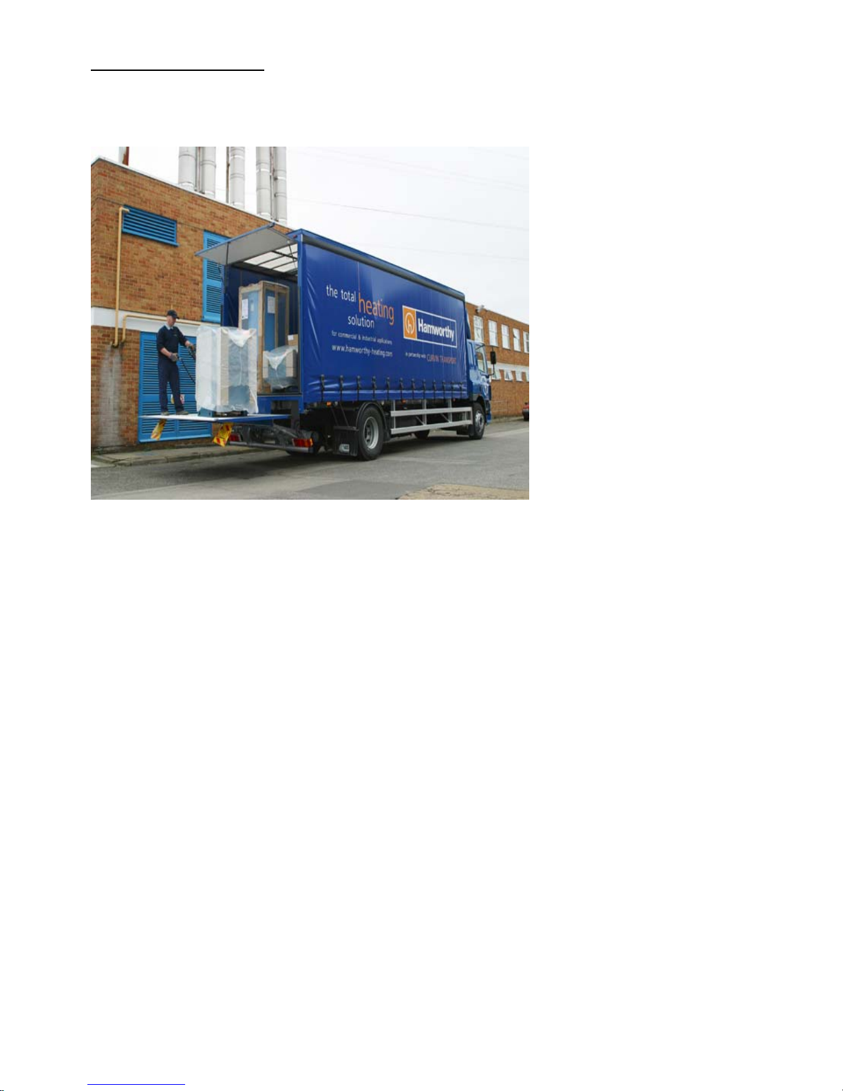
Your boiler is despatched to site as a pre-assembled and tested unit. Each boiler is delivered by a tail lift vehicle
and lowered to ground level. It is the installers responsibility to convey the boiler to the plantroom.
The base of each boiler is specially designed to accept a standard pallet truck. This allows the boiler to be
manoeuvred into position without any pallets to remove. Additionally the boiler is designed to pass through a
standard doorway where access is restricted.
NOTE: The boiler is supplied with cardboard corner protection and shrink wrapped for protection during handling.
However, when manoeuvring the boiler, care must be taken to avoid damage to the casing.
The boiler must be kept upright during handling. Care must be exercised to avoid toppling the boiler as this will
result in damage.
The flue connection & condensate trap to the boiler are packaged separately to avoid damage. The flue
components consist of an adaptor elbow, gasket and straight length of 150mm diameter flue pipe. The condensate
trap is supplied loose beneath the front cover.
Figure 2.1 - Boiler Delivery
Page 8

HAMWORTHY HEATING LTD
3
PUREWELL VariHeat he
500001155/F
Model Depth Width Height Weight
Purewell VariHeat he 65
1090mm 550mm 1310mm
205kg
Purewell VariHeat he 85
Purewell VariHeat he 105
Purewell VariHeat he 125
277kg
Figure 2.3 - Boiler Packaged Dimensions
Delivery Verification
When taking delivery please ensure that you have received the correct number of boilers and ancillary packages to
fulfil your order. If any item is missing please contact our after sales service team. Please provide details of your
order such as order number and contract number as well as a detailed description of the missing item.
Reverse Return Header Sets
Where reverse return header sets are used these are packaged separately from the boilers.
Ancillary items such as isolation valves and flexible boiler connectors are packaged in a cardboard box on the
same pallet. The whole is shrink wrapped for security and basic protection.
Model Configuration Length
mm
Weight
kg
65 - 85 he 2 boilers 1250 57
65 - 85 he 3 boilers
1784 95
65 - 85 he 4 boilers
2318 133
105 - 125 he 2 boilers
1250 112
105 - 125 he 3 boilers
1784 178
105 - 125 he 4 boilers 2318 300
Figure 2.5 - Header Kit Packaged Dimensions
Page 9
HAMWORTHY HEATING LTD
4
PUREWELL VariHeat he
500001155/F
3.0 SIZE AND SPACE REQUIREMENTS
3.1 The Purewell VariHeat he boiler range has been designed to utilise minimum floor space, therefore it is important the
plantroom has sufficient ceiling height to allow for installation and connection to the flue system.
A minimum distance of 50mm must be maintained from easily flammable materials
Also important is allowance for sufficient access at front, sides and rear of boiler for flue and pipework connections.
Ensure a minimum height of 150mm above the boiler for removal of the covers.
Do not run cabling through the top or display covers.
See Figure 3.1 below.
3.2 The Hamworthy Heating Ltd water manifold kit is designed to provide a compact solution for connecting the boilers to
the gas supply and flow and return water connections. (Refer to the Manifold Kit Installer’s Guide for specific details.)
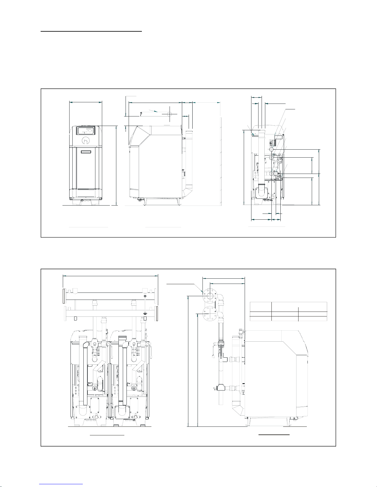
Figure 3.1 - Dimensions and Clearances
Figure 3.2.1 – Manifold Dimensions for a 2 Purewell VariHeat he boiler installation
393
150
71
260
1233
16
9
100 FLUE
330
515
456
1311
460
171
11 6
865
534
DATA LABLE
150 (MI N REC OMM END ED)
RETURN R 2" (PV105/125he)
FLOW R2" ( PV105/125he)
WARN ING LAB LE
F RONT VIEW A LL MODELS
SIDE V IEW ALL MOD ELS
REAR VIEW ALL MODELS
GAS R 1"
(AL L M ODE L S)
FLOW R2" ( PV65/ 85he)
RE TURN R 2" (PV65/85he)
PIPEWORK
570
470
12 90
C
D
Dimens ion
(mm)
C
D
PV 65/ 85h e
1650
1400
PV105/125he
1780
1540
Boiler Model
REAR ELE VATION
END ELEVATIO N
DN PN80 16
Page 10
HAMWORTHY HEATING LTD
5
PUREWELL VariHeat he
500001155/F
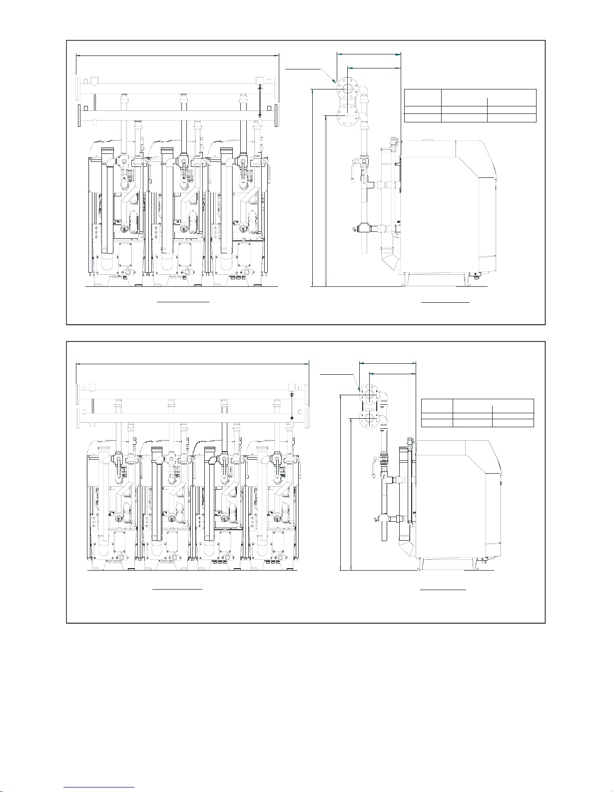
Figure 3.2.2 – Manifold Dimensions for a 3 Purewell VariHeat he boiler installation
Figure 3.2.3 – Manifold Dimensions for a 4 Purewell VariHeat he boiler installation
Safety Valve: As each kit is provided with a 3 port isolating valve for use on the flow pipe, individual safety valves are not
required on each module and a common valve can be fitted in the combined flow pipe. However, each boiler has a Rp1”
connection (plugged) in the rear of the boiler heat exchanger assembly for use on applications where module isolating
valves are not of the 3 port type..
47 0
C
23 5 8
D
RE AR ELEVAT ION
END ELEVATION
Dimension
(mm )
C
D
PV65/85he
1650
1400
PV105/125he
1780
1540
Boiler Model
57 0
DN PN
80 16
470
C
D
1824
REAR ELEVATION
END ELEVATION
D imension
(mm)
C
D
PV65/85he
1650
1400
PV 105/125he
1780
1540
Boiler Model
57
0
DN PN
80 16
Page 11
HAMWORTHY HEATING LTD
6
PUREWELL VariHeat he
500001155/F
4.0 SITE LOCATION AND PREPARATION
4.1 Site Location.
• The floor or plinth for the boilers and water manifold kit must be both flat and level to
ensure correct alignment of fittings and connections.
• The floor or plinth must be sufficiently strong to support the weight of both the boilers
and manifold kit where used.
• The floor or plinth must be fireproof in accordance with BS 6644.
• The plantroom must have sufficient space for installation of boilers, manifold kits,
pipework, pumps, controls, flues, ventilation, access and servicing, and other items of
plant.
4.2 Gas Supply.
• Gas supply pipes must be in accordance with BS 6891 or IGE/UP/2
• Gas supply connection to the boiler must not be smaller than the connection on the
boiler - R1”
• Gas installation must be soundness tested to BS 6891 or IGE/UP/1 & IGE/UP/1A.
• Gas installation must be purged to BS 6891 or IGE/UP/1 & IGE/UP/1A.
• Inlet gas pressure to boiler should be nominal 20mbar (minimum 17.5mbar) dynamic at
the connection to the boiler.
• Boiler house gas isolation valve must be clearly identified and installed close to the
entrance / exit.
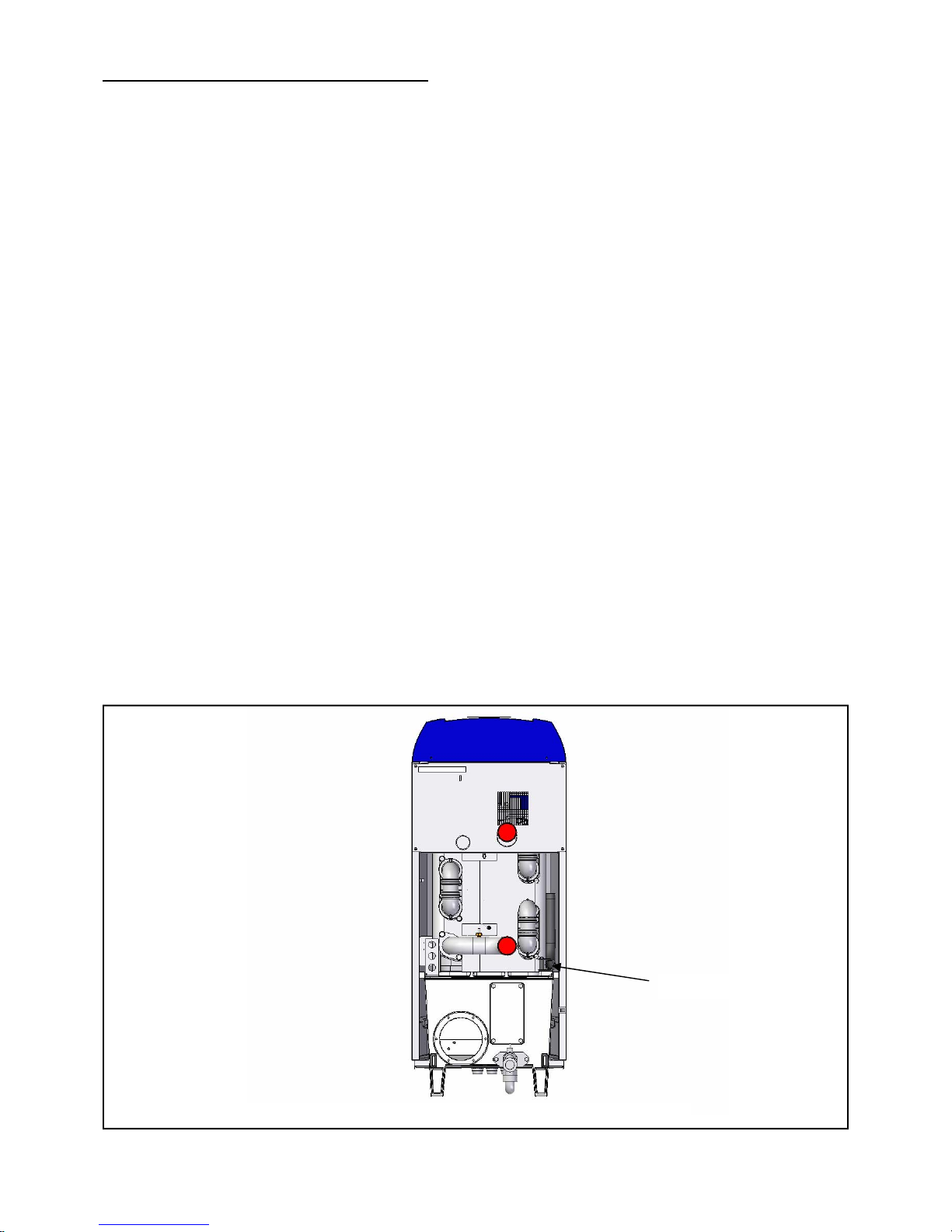
Figure 4.2 – Gas Connection Point
R 1” Gas Connection
Page 12
HAMWORTHY HEATING LTD
7
PUREWELL VariHeat he
500001155/F
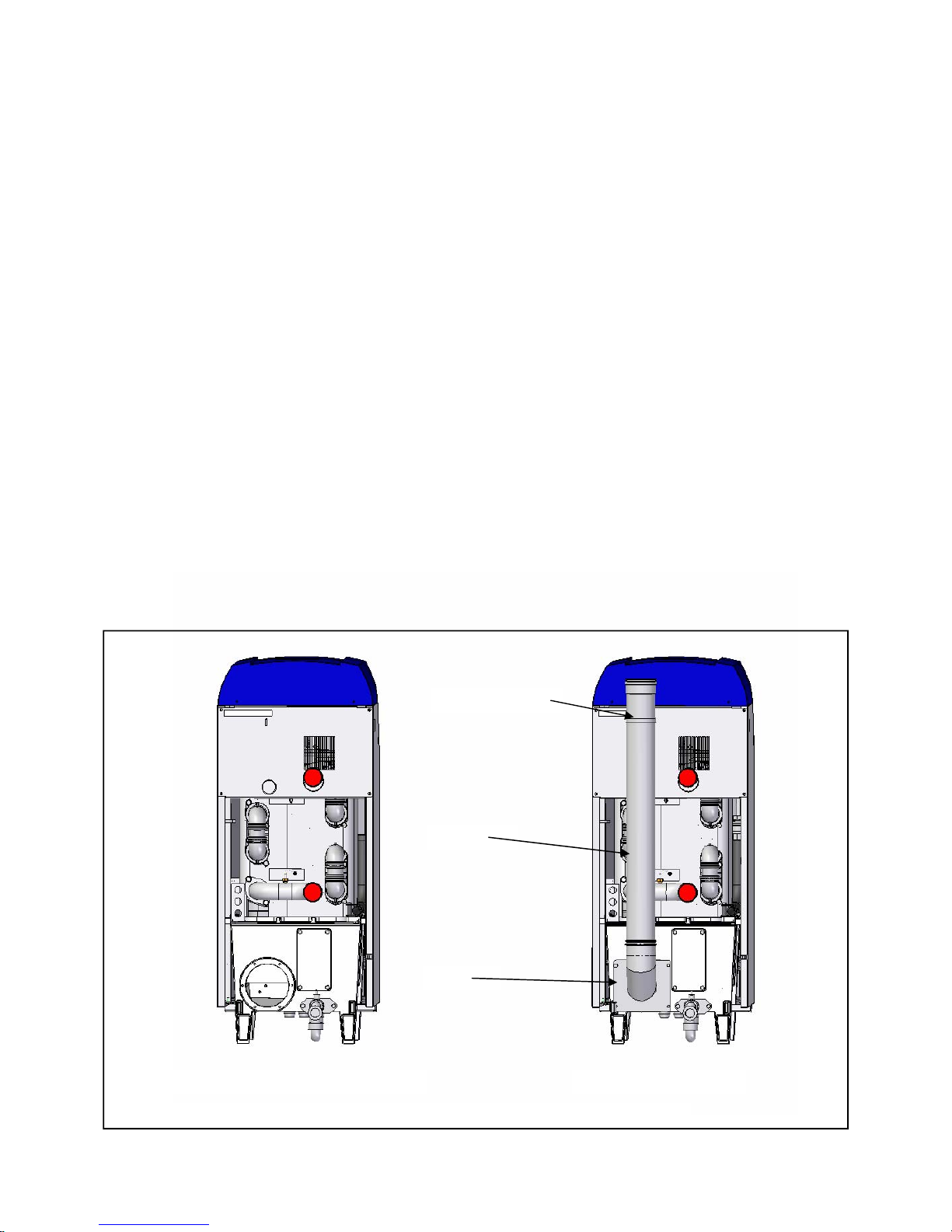
Figure 4.3 – Flue Connection Point
Flue Connection as delivered
4.3 Flues
•
Flue termination, routing and construction must comply with the requirements of the
Clean Air Act 1993—Chimney Memorandum, BS 6644 BS 5440 and IGE/UP/10.
•
Any flue must be self supporting and separable from the boiler for servicing
requirements.
•
Due to the possible flue gas temperature, 60 — 190°C, consideration must be given to
the construction and material of the flue system with fully sealed joints due to pressure
and condense in flue.
•
Flue construction is recommended of a twin wall, insulated type to maintain buoyancy
within the flue.
•
Care should be taken to ensure that the flue system is installed in such a way that any
condensation produced on start up, will drain away naturally.
•
Horizontal flue runs must be kept as short as possible and be inclined at minimum 2°
towards the termination.
•
The flue system must be designed acknowledging that there may be a positive pressure
generated by the boiler combustion fan. Refer to Appendix C - Fig C1.
• Connecting flue systems may be smaller in internal diameter than the boiler
connection. Refer to Hamworthy Heating Technical Dept for assistance.
Flue Connection fitted
Flue fixing bracket
Flue Pipe
Elbow
Page 13
HAMWORTHY HEATING LTD
8
PUREWELL VariHeat he
500001155/F
4.4 Water Supply
• Feed and Expansion tanks to comply with static height requirements of BS6880 &
BS6644.
• Cold feed and open vent pipes to comply with requirements of BS 6644.
• Pressurised system to comply with BS 7074.
• It is recommended that the system pipework is flushed twice before water
treatment.
• In hard water areas precautions such as water treatment should be implemented to
prevent the build up of sludge and scale.
• Leaks in the system pipework should be fixed to prevent dilution of water treatment.
• Maximum working water pressure is 7 bar.
• For minimum water pressure see Appendix ‘E’ - Water Data (Page 47)
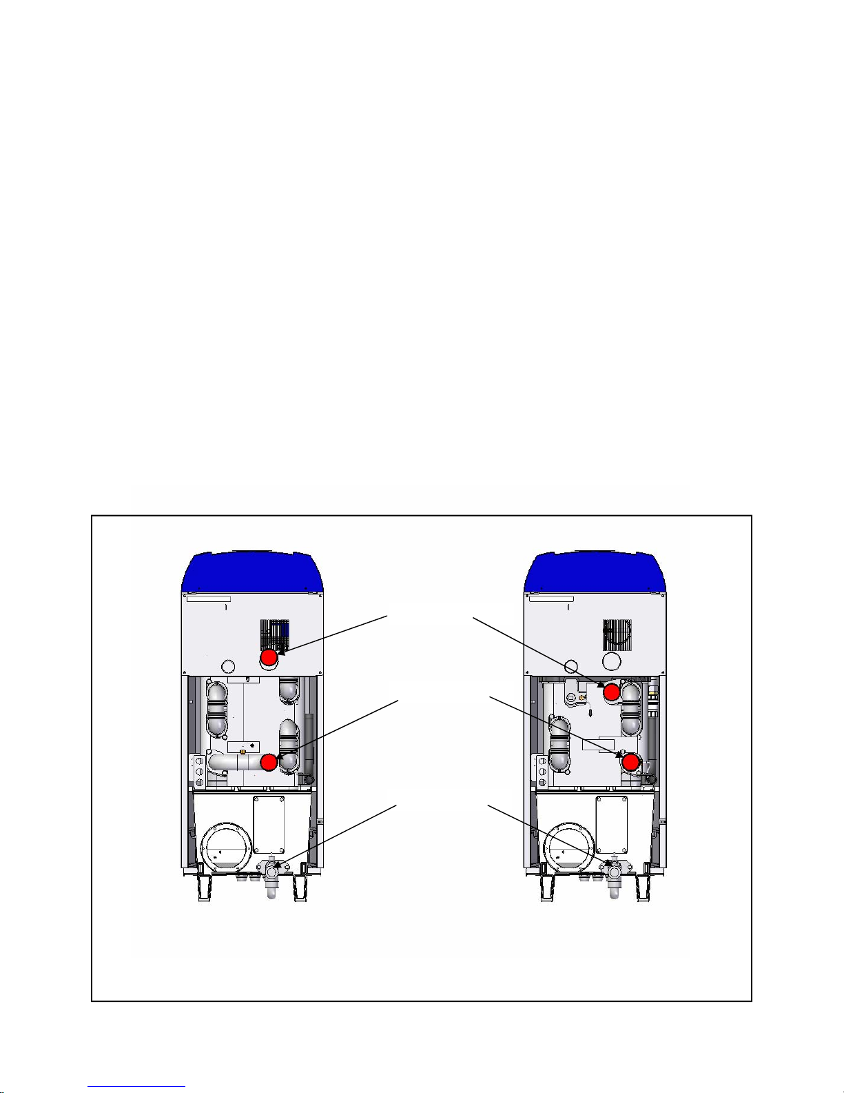
Flow Connection
Figure 4.4 – Water Connection Points
Return Connection
Model Type
PV65he & 85he
Model Type
PV105he & 125he
Condensate Take-Off
Page 14
HAMWORTHY HEATING LTD
9
PUREWELL VariHeat he
500001155/F
4.5 Condensate Connections
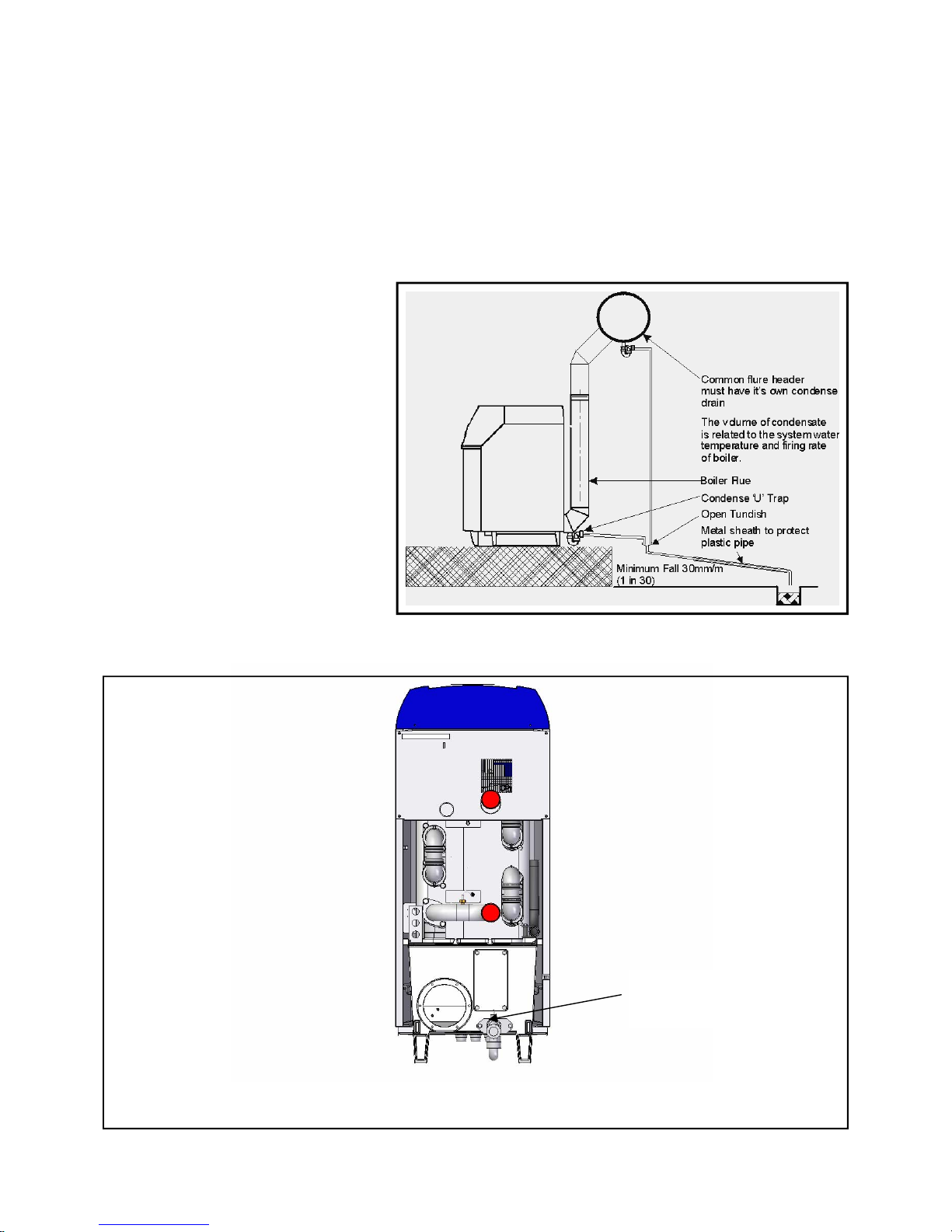
•
Provision must be made for removal of condensate from the boiler and flue system.
• Condense is mildly acidic, typically pH 3 - pH 5.
• Condense pipework must be non-corrosive and not copper. Hamworthy recommend
32mm dia. Plastic waste pipe.
• Condense may be discharged to a standard drain subject to National or Local
regulations.
Boiler Condensate
Connection
(32mm o/d)
Figure 4.5.1 - Boiler Condensate Pipe Work Installation
Figure 4.5.2 – Position Of Condensate Connection On Boiler
• Location of condense
pipework should prevent
freezing within
tundishes, traps and
pipework.
• Do not allow blockage or
damage to the
condensate trap.
• The connection to the
boiler condense drain
accepts a straight pushfit coupling for 32mm i.d.
plastic waste pipe.
Page 15
HAMWORTHY HEATING LTD
10
PUREWELL VariHeat he
500001155/F
4.5 ELECTRICAL SUPPLY
WARNING! THIS APPLIANCE MUST BE EARTHED IN ACCORDANCE WITH IEE
REGULATIONS
• Boiler electrical supplies must not be switched by a time clock.
• Boilers are suitable for 230Volt, 50Hz supply.
• External fuses should be rated for 6 amps
• Wiring must be completed in heat resistant cable size 1.0mm² csa.
• Each module should have individual means of isolation.
• Electrical isolators must facilitate complete electrical isolation.
• Electrical isolators must have contact separation of minimum 3mm in all poles.
• Electrical isolators must be installed in readily accessible locations.
• Electrical supplies to boiler modules should only serve the boiler.
• Where volt free contacts are used, these too must be individually isolatable.
• Time clock control should be via the boiler modules Remote On/Off circuit (30V DC).
Any circuit connected to the Remote On/Off MUST be volt free
ADDITIONAL INFORMATION REGARDING ELECTRICAL SUPPLIES IS GIVEN IN BS
EN60335, Part 1.
NOTE: The appliance must be isolated from the electrical supply if electric arc welding is
carried out on connecting pipework.
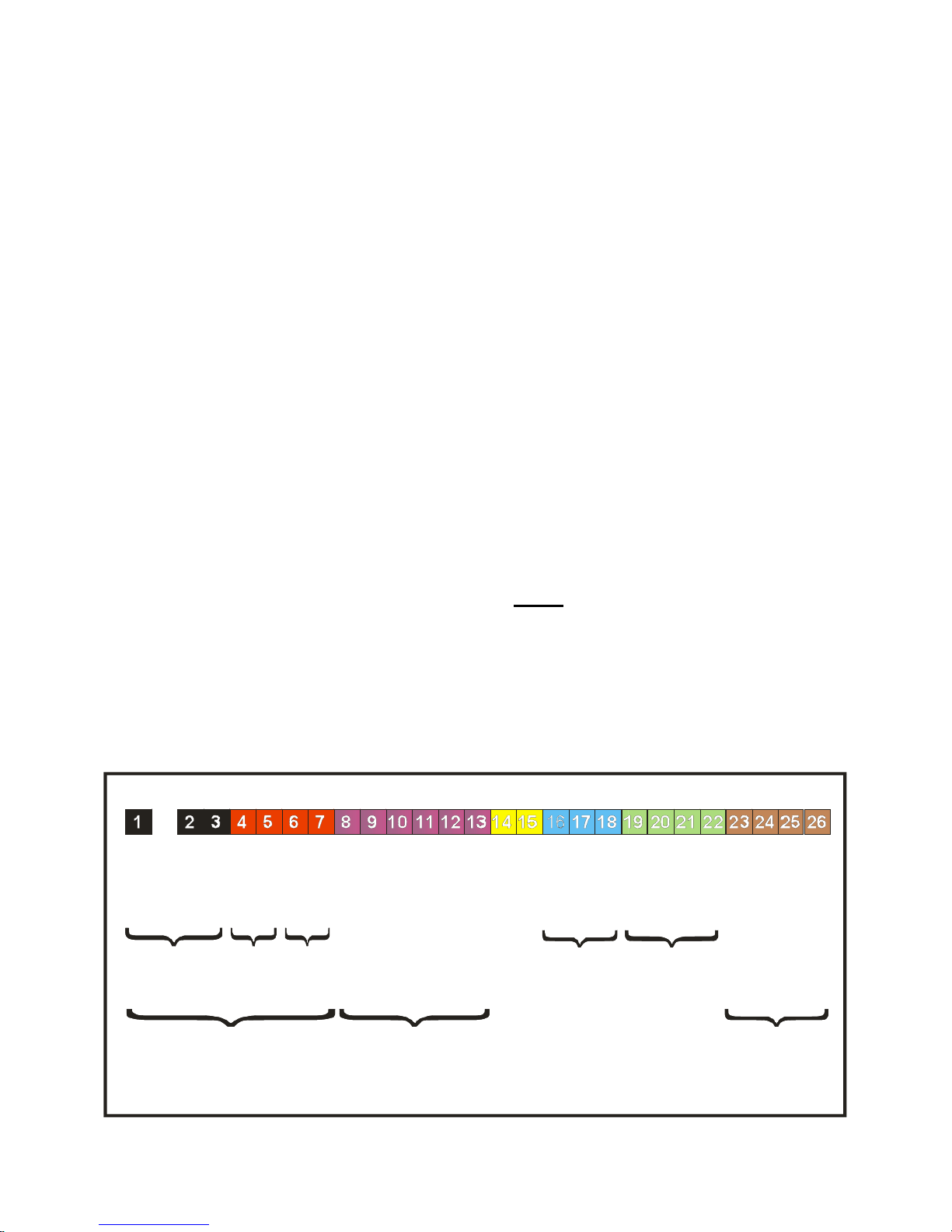
FOR DETAILED WIRING INSTRUCTIONS SEE SECTIONS 5.3, 9.0 & APPENDIX B
Figure 4.5 - Electrical Connections
Earth
Neutral
Neutral
Neutral
Live
Live
Live
Overheat
Overheat
Normal Run
Normal Run
Common Fault
Common Fault
0~1 0v
Sig nal
Outside
Sensor
Sens or
Master Screen
Slave S creen
Ca scade
Ground
Ground
Rem ote On/ Off
Remote On/Off
Mains
6A
Signal
Sensors
230v~50Hz
Volt free contacts
Max 230 v 2A
Cascade
Shunt
Pump
Output 1A
Primary
Pump
Output 1A
4~20mA
Page 16
HAMWORTHY HEATING LTD
11
PUREWELL VariHeat he
500001155/F
5.0 BOILER ASSEMBLY
General
Boilers are despatched to site as fully assembled units. The flue pipe, condensate drain connection and pipework
manifold set (where applicable) are the items that will need assembling on site.
During assembly it is important to take care to prevent damage to the boiler casing. DO NOT STAND ON THE
CASING PANELS.
Boiler positioning must allow the minimum clearances detailed in Section 3.0 to facilitate access for flue and
pipework connections as well as maintenance. Boilers can be positioned side by side, no clearance is necessary.
5.1 Flue Pipe
So as to avoid damage, the flue connecting pipe is supplied separately.
Fit the elbow to the base of the boiler and secure using the gasket and 4 - M8 x 16 Hex Head Screws. Moisten the
lip seal and engage the flue pipe into the elbow. Secure the flue pipe to the boiler casing using the bracket
supplied.
5.2 Water Connections:
Connecting pipework must be self-supporting to avoid stress on the boiler connections. Local unions are
recommended in the pipework to facilitate future servicing requirements.
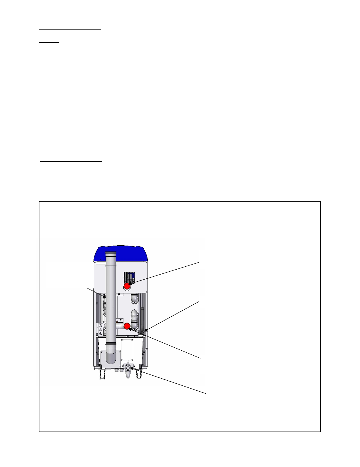
The following connections are provided on each boiler module;
Figure 5.2.1 - Rear Water Connections
Flow R2” Male thread. Indicated by a
red dot on boiler.
Gas R1” Male thread.
Return R2” Male thread. Indicated
by a blue dot on boiler.
Rp1”
Safety Valve
(behind flue pipe)
Condensate Trap
Page 17

HAMWORTHY HEATING LTD
12
PUREWELL VariHeat he
500001155/F
Open Vented Systems
Boilers must not be capable of isolation from the vent pipe. Valves between boiler and vent pipe to be three way
type such that when boiler is isolated from vent pipe it is open to atmosphere. Safety valves should be mounted
on the boiler using the connection provided.
Sealed Systems
Boilers must not be capable of isolation from the safety valve. Valves between boiler and safety valve to be three
way type such that when boiler is isolated from safety valve it is open to atmosphere. Hamworthy Heating Ltd
provide a connection on the boiler for the safety valve .
Where using Hamworthy Heating Ltd pipework kits, assembly of these is detailed in the Instruction manual
supplied with kit.
5.3 Electrical Connections:
The following electrical connections are provided on each module on a rail at the base of the front of the boiler.
• Supply: Live, Neutral and Earth. See Section 4.6 for details.
• Live and Neutral connections for Shunt pump or Primary Pump
• Boiler Overheat Fault Alarm Signal Output
• Common Fault ie A Boiler Ignition Lockout Or Fault Alarm Signal Output
• Boiler Normal Run Signal Output
• Remote On/Off
• 0-10v Analogue Control Signal Input
• External sensors
• Cascade Management of Multiple Boiler Installations
Page 18

HAMWORTHY HEATING LTD
13
PUREWELL VariHeat he
500001155/F
6.0 PRE-COMMISSIONING
The following checks must be carried out before the boiler is commissioned.
6.1 Gas Supply.
Ensure that gas installation pipework and meter have been soundness tested and purged to IGE/UP/1 or IGE/
UP/1A as appropriate. Test and purge certificates should be available for viewing.
6.2 Ventilation
Ensure that ventilation and air supply to plantroom is correct - refer to Appendix D (page 46). Air supply around the
rear of appliance is unobstructed.
6.3 Pipework, Valves and Pump
Ensure that;
• Pipework and valve arrangement is installed to Hamworthy Heating recommendations.
• Circulating system is full of water, vented and pressurised appropriately.
• Circulation pump is fitted, working and interlocked where required.
• Pipework connections to boiler are fitted correctly.
• All necessary isolation valves are open.
• Safety valve is correctly sized and located.
• Heat load is available.
6.4 Flue
Ensure that;
• Flue system is correctly designed and installed to suit boilers.
• Flue passages to chimney are clear.
6.5 Electrical
Ensure that;
• Electrical connections are correct and isolatable.
• External controls are operational.
WARNING: IF THE FRONT COVER IS REMOVED WHILST THE BOILER IS OPERATIONAL,
CARE MUST BE TAKEN WITH ELECTRICAL COMPONENTS AND ACCESS TO PRIMARY
INSULATION.
Page 19
HAMWORTHY HEATING LTD
14
PUREWELL VariHeat he
500001155/F
7.0 CHECKS PRIOR TO LIGHTING
IMPORTANT: BEFORE PROCEEDING TO LIGHT THE BOILER, ENSURE THAT THE PRE-
COMMISSIONING CHECKS HAVE BEEN CARRIED OUT AND THE RESULTS SATISFACTORY.
7.1 Boiler Gas System Leak Check
Ensure that the appliance manual gas service valve is in the OFF position. Although the boiler receives a gas
leak check and gas train component integrity check prior to leaving the factory, transport and installation may
have caused disturbance to unions.
A procedure guide is given below. Care must be taken not to allow leak detection fluid on or near any electrical
parts or connections.
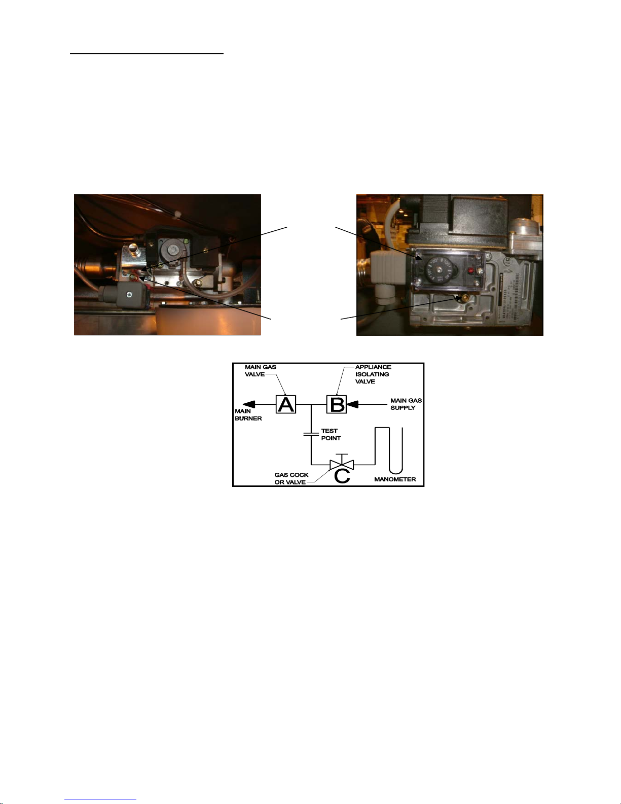
Figure 7.1.2 - Gas System Leak Check Diagram
Note: - Main gas supply pressure - G20 - 20mbar
To Check Valve B
1) Turn off the electrical power and gas to the appliance.
2) By unscrewing screw at Position X of Figure 7.1.1 remove the red gas pressure switch (L.H.S picture) or loosen
the test point valve plug (R.H.S picture).
3) Connect the manometer to gas valve test point.
4) With A, B closed open C and monitor manometer over a 2 minute period, a rise indicates a leak on valve B.
5) Reinstall red gas pressure switch or shut valve plug in test point.
To Check Valve A
1) Repeat steps 1, 2, 3 & 5 above.
2) Open C.
3) Open B to produce the main gas supply pressure between A and B.
4) Close B
5) System may be considered sound if over a period of 2 minutes any drop in pressure is less than 0.5 mbar
(0.2" wg.).
NOTE: Allow a manometer stabilisation period of approximately 1-minute before each 2 minute check period. Following soundness tests close valve B and remove manometer connections and tighten test points.
Figure 7.1.1 - Test Point Locations On Gas Valves
Position X
(Test Point)
Low Gas
Pressure
Switch
Page 20
HAMWORTHY HEATING LTD
15
PUREWELL VariHeat he
500001155/F
7.2 Checks Prior to lighting the boiler
NOTE! Refer to Appendix A for Natural Gas maximum gas inlet pressure for normal operation.
The following checks must be made prior to lighting the boiler.
If satisfactory, refit the bulb in the pocket and secure
with the clip. Ensure that all thermostat bulbs/sensors
are fully inserted into the pockets. The flow and return
temperature sensors are located at the rear of the
boiler in the flow and return pipes.
3) Check setting of both temperature limit thermostat
and control thermostat. The limit thermostat is set at
95°C. To remove the limit thermostat, found on the rear of
the display fascia bracket removing the plastic display
cover and unscrew the fixing screws securing the
thermostat from its mounting plate.
The control thermostat is factory set to a flow temperature
of 85°C and must be re-set to suit the application using
the process detailed in section 8.7.2.1 - Controls
Operation
4) To ensure correct ignition of the boiler it is
recommended to check the resistance of the hot
surface igniter. This should be checked cold, using a
suitable ohmmeter, by disconnecting the igniter from
the control panel cable and measuring the resistance
across the pins of the 2 way connector. The reading
should be between 70 and 110 ohms.
7.3 INITIAL LIGHTING
Only competent persons registered for working on non-domestic gas appliances should attempt the following
operations. Before attempting to commission any boiler, ensure that personnel involved are aware of what action
is about to be taken.
Record all readings for future reference on relevant commissioning sheet.
Allow system to warm up sufficiently to check operation of control thermostat.
A combustion check must be taken when first commissioning the boiler. A sampling point is provided in the base of the
boiler.
NOTE! Care should be exercised when the boiler is firing as the flue components can achieve temperatures, which
could cause injury if touched.
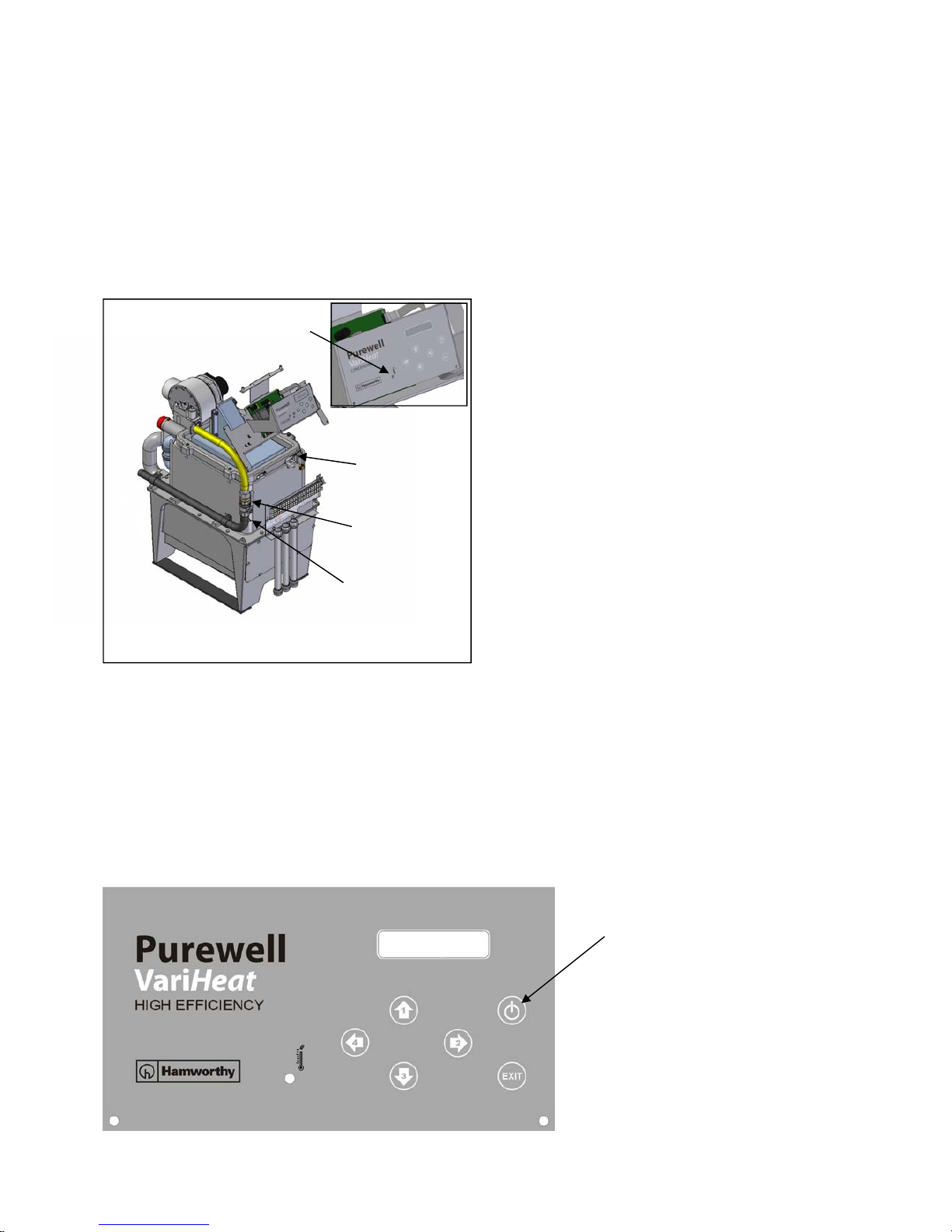
Figure 7.2.1 Gas Isolating Valve
Boiler On/Off - Enter - Reset
Gas
Isolating
Valve
1) Ensure that the gas supply is connected but turned to the "off" position. Any unions or fittings are correctly tightened, test points are closed, and that the ignition and probe leads are connected correctly.
2) Ensure the electrical mains supply is correctly connected but the boiler isolator(s) are switched off. Check all
wiring loom connections such as fan and gas valve, are correct and secure. Test the operation of the safety temperature limit thermostat (Limit Stat) by removing the clip & bulb from the pocket in the front of the heat
exchanger, and carefully apply a heat source to the bulb. The Limit Stat reset button should lift & protrude through
the hole in the controls fascia. To reset, firmly press the button through the access hole in the controls fascia
using a terminal screwdriver.
Gas Pressure
Test Point
Position Limit
Thermostat
Reset
Figure 7.3.1 Boiler Facia Display
Position Of
Viewing
Window
Page 21
HAMWORTHY HEATING LTD
16
PUREWELL VariHeat he
500001155/F
6) On Failure to sense presence of a flame the boiler will go to
lock-out.
7) Turn off the gas & electrical supplies to the boiler.
8) Carefully reconnect the electrical plug to the gas valve and
secure with the appropriate screws.
9) Turn on the gas and electrical supplies to the boiler and press
the reset (Enter) button to remove the ‘lockout’ condition.
The boiler will commence the ignition sequence. This time when
the gas valve is energised, the gas will light.
• At the end of the 5 second ignition proving period, the hot
surface igniter will be switched off and the fascia display will
change to “ BLR:RUN” .
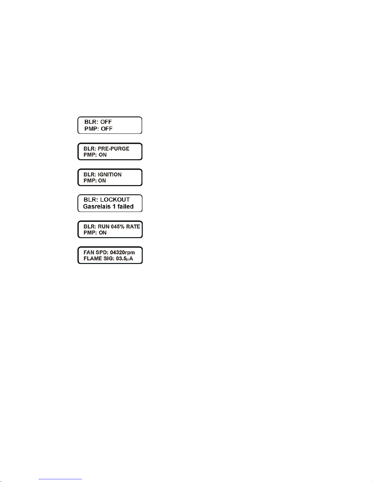
• After a period of 15 seconds the fan will alter speed and the
burner modulation will be set according to the heat load.
• If after the 5 second flame proving period the flame signal is
below 1µA the boiler will shut down and attempt one restart.
As the boiler approaches the set point temperature, the % rate will
reduce on the display from 100%
7.3.2 Safety Checks
7.3.2.1 To check for correct operation of the controller, with the boiler running, carefully disconnect the flame
probe lead from the flame probe.
The boiler will shutdown, attempt to relight once & then lock out causing ’no flame ign’ to appear on the display.
Carefully reconnect the probe lead then press the reset (Enter) button to recommence the light-up sequence.
7.3.2.2 With the boiler firing, turn off the gas isolating valve and the boiler will shut down in ‘Blocked’ ‘ mode
showing ‘BLR:Low Gas Pres’ on the display. Wait at least 30 Seconds before opening the gas Isolating valve
when the block will clear and the boiler will recommence the light-up sequence.
7.3.3 Flame Signal Assessment
The flame ionisation signal generated whilst the boiler is firing, can be viewed directly from the display screen.
The value is set to read dc µA. Refer to 8.7.1.3.
7.3.4 - Adjusting the settings of the boiler
The desired Flow temperature setpoint can be set as follows:
With the boiler showing one of the Status Screens, by pressing the Up / Down key a further screen is presented
showing the actual setpoint (factory set to a maximum flow temperature of 85°C). Further pressing of the Down /
UP keys will increase or decrease the setpoint in 0.5°C increments within the limits set in the program.
After changing the setpoint to the desired value the ‘Enter’ key must be pressed to store the value.
Note: the screen will revert back to the normal Status Screen after a few seconds.
Should a set point higher than 85°C be required, please contact Hamworthy Heating, as programming for
a higher maximum outlet temperature is restricted by a factory set access code.
7.3.1 Lighting the boiler
1) Ensure that both gas and electrical supplies are isolated from the boiler.
2) Disconnect the electrical plug to the gas valve by loosening the securing screw(s) and pulling off.
3) Turn on the gas (see Figure 7.2.1) and electrical supplies to the boiler. A gas supply pressure above 12.5 mbar
will remove the Low Gas Pres block and the fascia display will read BLR:OFF
PMP:OFF
4) To initiate the start-up sequence, press the On/Off (Enter) button. The boiler will run through it’s start-up
sequence and the display will change as per figure 7.3.2 providing that the remote on/off contact is made and/or
the BMS system is in demand.
5) Check that the Hot surface Ignitor begins to glow, by looking inside the boiler through the oval viewing window
within the recess at the top right hand side of the boiler. (At this point, no gas is present in the boiler so no ignition
occurs).
Figure 7.3.2 - Start Up Display Sequence
Page 22
HAMWORTHY HEATING LTD
17
PUREWELL VariHeat he
500001155/F
7.4 Combustion Checks
The boiler is factory preset. However, where checks need be undertaken during servicing to confirm correct
performance within the installation:
1) Put boiler into service mode (Section 8.5.1 Page 21) to enable the High & Low CO
2
figures to be measured.
2) Remove the sample point plug from the front of the base of the boiler.
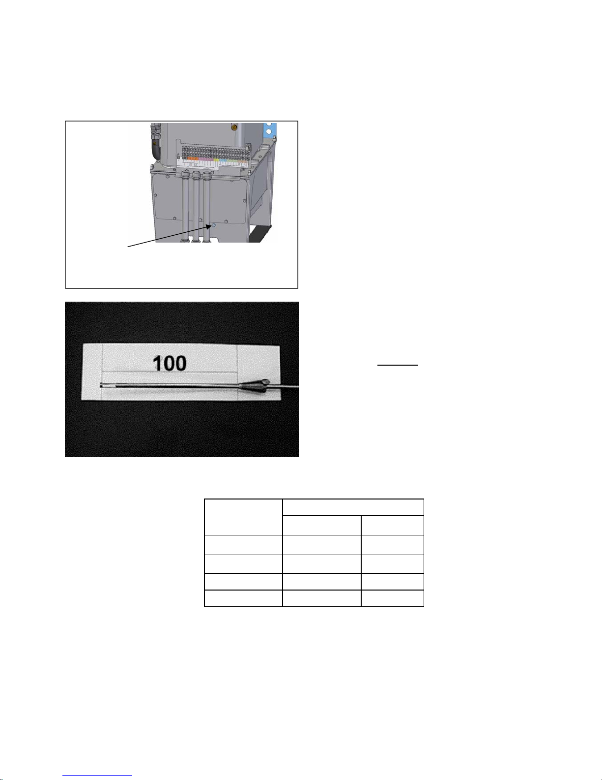
3) Ensure that an insertion distance of 100mm is set on
the combustion analyser probe.
NOTE: THIS DISTANCE MUST BE SET TO ENSURE
ACCURATE ANALYSIS OF THE FLUE GASES.
4) Insert the probe into the base up to the set stop
position .
5) For high & low fire target CO
2
figures, see table
below.
6) CO = 0-50ppm: however figure should not exceed
200ppm under normal operating conditions.
7) If the combustion readings fall within the required
range, the boiler is set and operating correctly.
8) Remove the combustion analyser probe & replace
the sample point plug in the front of the base of the
boiler.
9) If the combustion readings fall outside the
required range DO NOT
adjust the gas valve
settings .
CONTACT HAMWORTHY HEATING SERVICE
DEPARTMENT.
10) Tampering with any sealed component may
result in loss of warranty on the appliance.
Flue Gas Sampling Point
Figure 7.4.1 - Removal of Sample Point Plug
Figure 7.4.2 - Combustion Analyser Probe Setting
11) Refer to section 8.0 - Controls Operation, to set the relevant boiler parameters and timings specific to the
installation.
7.5 User’s Instructions
The boiler owner or their representative should be made aware of the lighting and operating instructions.
A practical demonstration should be given describing each functional step. This Installer's Guide and User’s
Instructions should then be handed over & kept in a safe place for easy reference.
% CO
2
+/- 0.25%
HIGH FIRE LOW FIRE
PV65he 8.5 8.5
PV85he 9.5 9.0
PV105he 9.0 8.5
PV125he 9.0 9.0
BOILER MODEL
Table of Combustion Settings
Page 23
HAMWORTHY HEATING LTD
18
PUREWELL VariHeat he
500001155/F
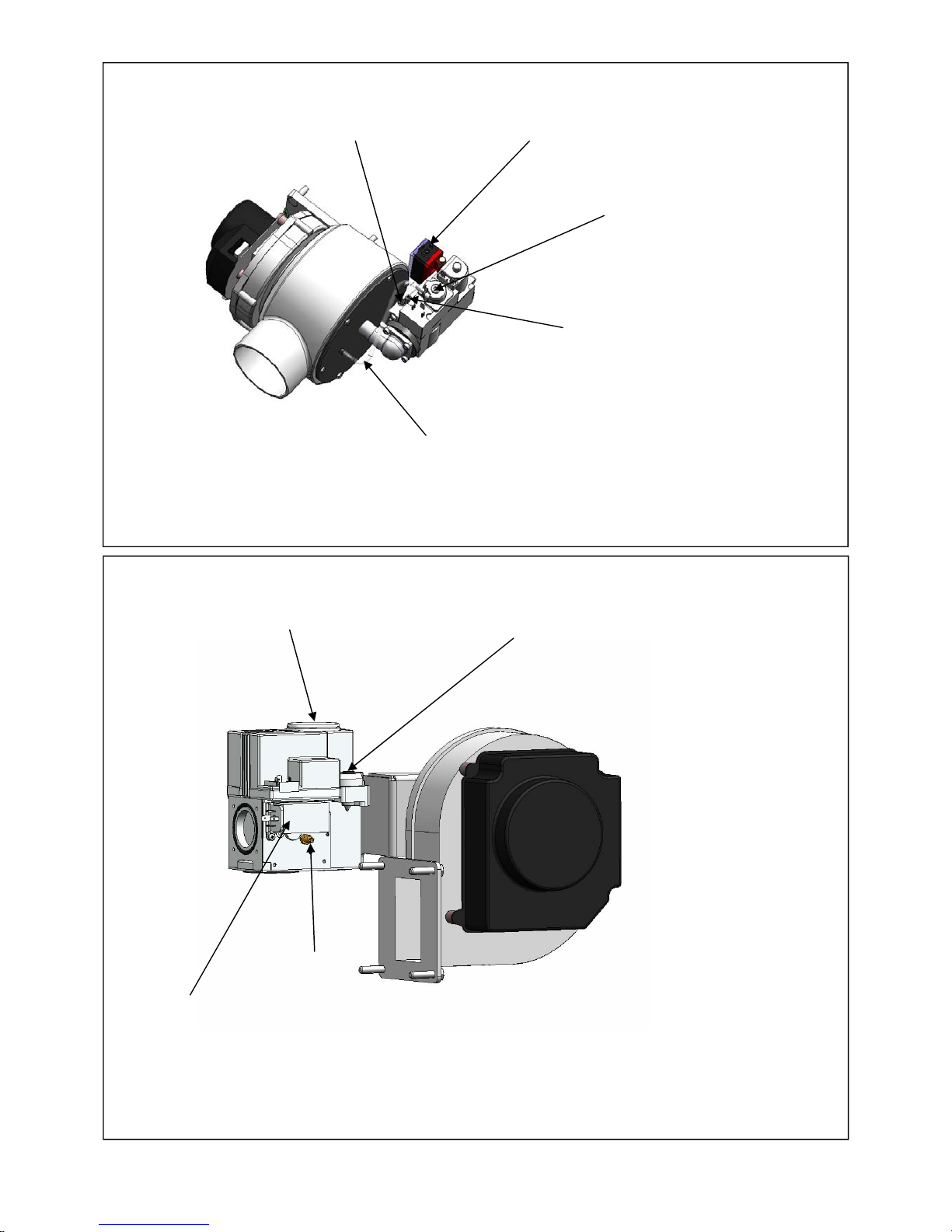
Figure 7.4.4 - Fan Assembly PV105he & PV125he
Figure 7.4.3 - Fan Assembly PV65he & PV85he
High Fire Gas / Air
Adjustment Factory
Sealed
Pressure Feed
Back Tube
Outlet Gas
Pressure
Test Point
Low Fire Gas Adjustment
Factory Sealed
Pressure Switch
Pressure Switch
Low Fire Gas Adjustment
Factory Sealed
High Fire Gas / Air
Adjustment Factory
Sealed
Outlet Gas
Pressure
Test Point
Page 24
HAMWORTHY HEATING LTD
19
PUREWELL VariHeat he
500001155/F
8.0 CONTROLS OPERATION
Overview
The Purewell VariHeat he control system is a self contained, microprocessor based package (BIC930), controlling
and monitoring all safety and functional aspects of the boiler performance and it’s integration with external system
controls.
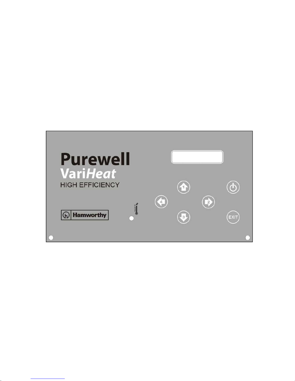
Access to boiler performance information is via the DU930 display screen consisting of 2 x 16 character backlit
LCD unit and 6 buttons for operation and setting of the boiler.
The system is compatible with BMS (or other) external controls via an enable or 0~10V DC input signal. The optional outside and mixed flow sensors are supplied by Hamworthy Heating Ltd to ensure safe and reliable operation.
The system provides as standard 3 volt free contacts for external fault indication - Normal Run, High Temperature
Overheat & General Fault.
The BIC930 control system allows the connection of multiple boilers on an RS485 bus connection (twisted pair) to
enable Cascade control of up to 8 multiple boilers by selection of Master/Slave configuration.
Note: To ensure safe and reliable operation, all wiring between sensors & master/slave boilers must be separated
from mains voltage wiring.
Figure 8.0 - Boiler fascia panel
General Description of Controls Functionality
8.1 Starting Up
During the first 3 seconds of any start-up, the internal micro-processor carries out a self-test to ensure correct
operation, prior to the fan commencing the Pre-Purge period at the defined speed. If a test fails, the control will go
to lockout.
If the flame signal is lost during any ‘Demand’ period, the gas valve will close immediately and if the flame cannot
be re-established after one attempt to relight, the boiler will go to lockout.
In the case of a lockout caused by ignition failure or overheat temperature, the fan will continue to run for a period
after the lockout has been instigated.
Ignition will start after the Post Purge time. Once the ignition speed has been achieved, the Hot Surface Igniter
(HSi) will be powered up to ensure that it is up to temperature when the gas valve is opened.
8.2 Stand-By
In Stand-by mode the boiler can still be programmed either through the display or PC tool software
Page 25
HAMWORTHY HEATING LTD
20
PUREWELL VariHeat he
500001155/F
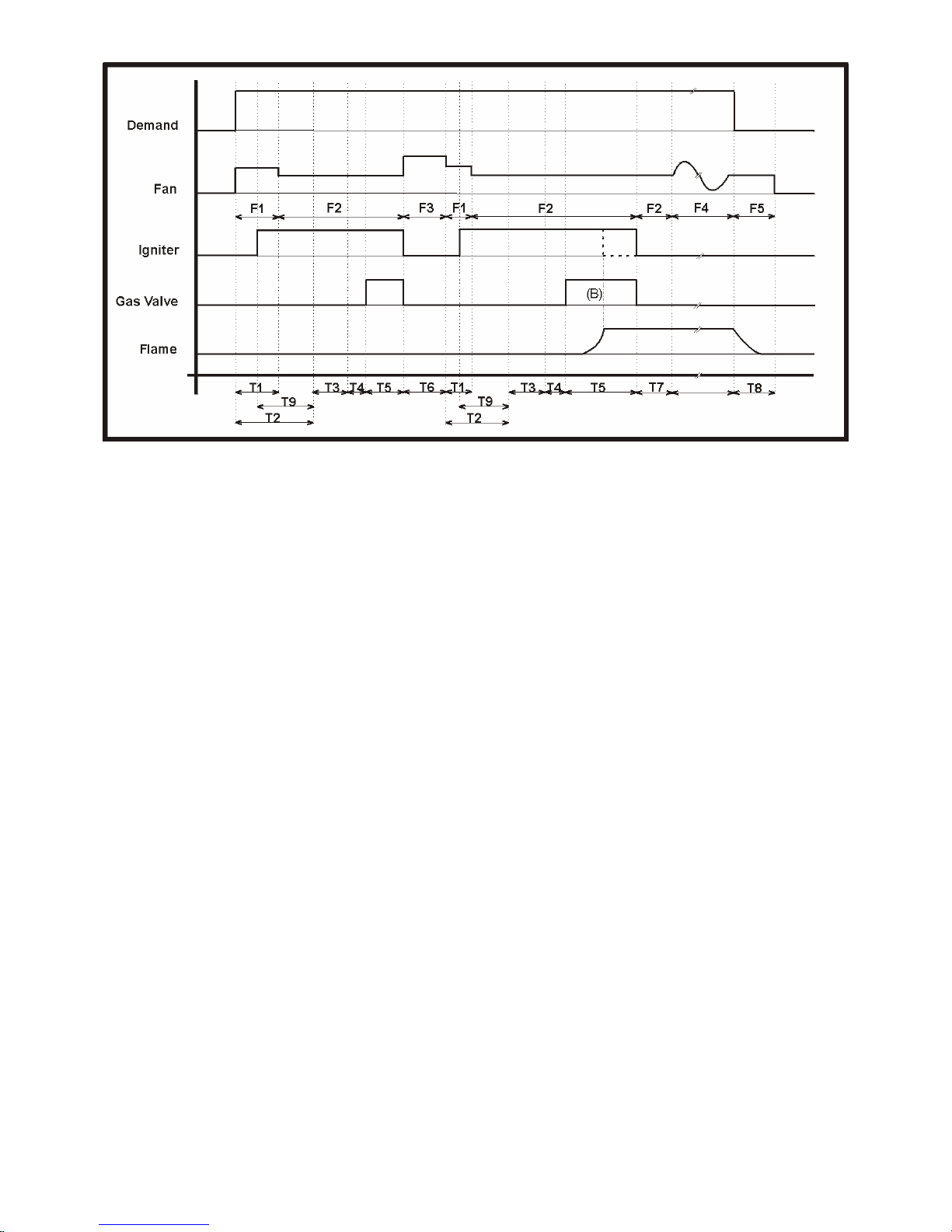
Figure 8.1 - Burner Control Logic Diagram
Legend
F1: Fan High Speed
F2: Fan Ignition Speed
F3: Fan Max. Speed
F4: Fan Free Modulation
F5: Fan Post Purge
T1: Fan High Time
T2: Pre-Purge Time
T3: Pre-Ignition Time
T4: Relay Test Time < 0.8s
T5: Safety Time
B): Ionisation current switches
off HSi
T6: Post Purge Time
T7: Flame Stabilisation Time
T8: Flue Gas Purge Time
T9: Warm up Time HSi
With no heat demand, the pump (if connected) can either be running (pump overrun time) or ‘kicking’, once every
24hrs, to prevent pump seizure.
8.3 Pump Kick
The kick time is programmable. If the control is set as a Master in a cascade multiple boiler arrangement, the kick
function will operate the ’primary pump’.
8.4 Lockout
The micro-processor is able to distinguish two types of ‘Lockout’, namely;
- LOP. “Lockout Processor”
This is when the control detects a serious internal fault (due to corrupt parameter from EEPROM, corrupted flash
memory, too many restarts after detecting a fault..etc) the control will lock-up and nothing will work including reset,
with the display registering the last message. The only way to reset is to switch off the mains power for at least 5
seconds. Should this procedure have to be repeated several times without resolving the problem, it is advisable to
replace the control.
- LOF. “Lockout Functional”
This is when the control detects a serious functional fault, the control will go to lockout and nothing will work
except the reset button. In certain lockouts, the fan will be driven to High speed for 1 minute such as during: Safety Limit Thermostat or Overheat Limit Thermostat activation
Loss or lack of flame during running or ignition
A Gas Valve fault
In other lockout modes, the fan will not be switched on. In cascade mode, the primary pump will run for the pump
overrun time.
If there is a power failure during a lockout, the control will return to lockout when the power is returned.
The alarm relay is only powered in the event of an alarm situation. During normal operation, the alarm relay is not
powered.
Page 26
HAMWORTHY HEATING LTD
21
PUREWELL VariHeat he
500001155/F
8.5 Heat Demand
Depending upon the setting of parameters, the demand can be activated under the priorities detailed in figure
8.5.1
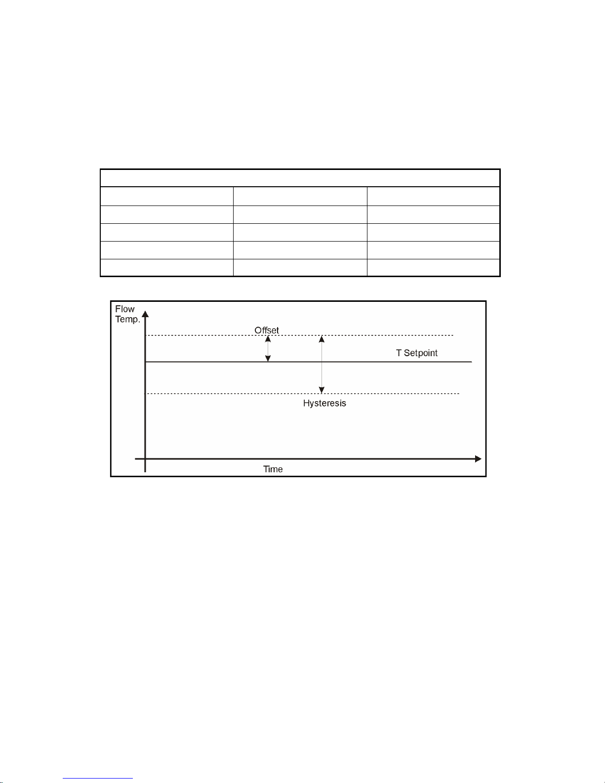
During normal operation, if the flow temperature exceeds it’s maximum setting, all further demands are blocked
and a programmable anti-cycling timer starts. The block will be removed when the flow temperature has dropped
below the offset maximum value. In addition, there is a hysteresis band on the return temperature at the
instigation of the block, which ensures that the boiler will be blocked, should the flow temperature drop very
quickly, until the return temperature is outside of the hysteresis band - see figure 8.5.2.
Each heat demand (Cascade, BMS, Heating etc.) has it’s own set of parameters for setting the offset and
hysteresis.
Heat Demand Activated by Mutual Priority
Service Mode Display Screen 1
Cascade RS 485 Protocol 2
Boiler Management System Analogue Input (0~10 Vdc) 3
Heating Remote On/Off or Thermostat 4
Frost Protection Low return temperature 5
Figure 8.5.1 - Priority Heat Demands
Figure 8.5.2 - Temperature Offset and Hysteresis
8.5.1 Service Mode
The Service Mode can be only accessed if the boiler does not display a ‘lock-out’. To clear a ’lock-out’ press the
enter button to reset the boiler. To access the service mode press the ‘Exit Button’ for 5 seconds. A four digit
numerical code must be entered to enable the engineer to access the programming functions necessary to
commission the boiler. Use the buttons with vertical arrows to select each number (from 0-9) in the 4 digit code
required. The horizontal buttons enable a position in the four digit sequence to be selected. As soon as the correct
code has been entered, the Service Mode will start (refer to Hamworthy Heating Ltd for service code). To exit the
Service Mode press the on/off (Enter) button. If during Service Mode operation, no buttons are pressed, after 40
minutes the boiler will revert back to normal operation under the previous demand. Activation of the Service Mode
overrides all other heat demands. During Service Mode, all safety devices remain active with the flow temperature
controlled to the maximum setpoint.
When entering the Service Mode, the fan speed will be held at the level prior to entering Service Mode and if in
Standby, will be held at the ignition speed. During the Service Mode function, the fan speed can be adjusted by
pressing buttons 1 or 3 to achieve the desired level (in increments of 10 rpm). After changing the fan speed, the
screen will display the new setpoint for 3 seconds and then revert to the boiler ON Status Display screen—see
figure 8.7.
Page 27

HAMWORTHY HEATING LTD
22
PUREWELL VariHeat he
500001155/F
8.5.2 Cascade
This function is only operational when the relevant parameter has been set. The BIC930 control can operate
upto 8 modules in cascade control with one module having to be designated Master and the others as Slaves.
Each module will require setting up.
8.5.2.1 Communication
When a Slave has been connected to the bus, the Master (0) detects the connected Slave by it’s unique address( 1...7). Should a connected Slave be at lockout or not recognised by the Master, it will not participate in
the cascade. However, if the Slave is switched Off by the On/Off button, it will still participate and the Master will
adjust the cascade acknowledging the loss of capacity.
In communication between the Master and Slaves, having sent a message, the Slave will respond within 0.5
seconds. If the response fails the first time or the response is corrupted, the Master will resend the message. If
the response fails again, the Master will remove the Slave from the cascade and adjust the capacity amongst
the Slaves responding. The Master will then check for a correct response from all Slaves every 15 seconds.
8.5.2.2 Cascade Regulation
Regulation of the heat demand is based upon the actual flow temperature and the desired set-point, calculated
by the heat curve and User setting. Should there be no mixed flow sensor fitted, the Master will allow all Slaves
to operate at maximum power
Adjustment of the proportional band and integral gain parameters is possible depending upon the installation.
With the cascade running two or more boilers, should the flow temperature exceed the set-point, the cascade
will try and manage the temperature to the set-point by switching off the boilers until only one boiler is firing. At
which point the blocking function will be implemented until the flow temperature is below the hysteresis level.
Should a Slave not receive a message from the Master (due to a problem with that boiler) within 20 seconds,
provided that the Remote On/Off input is closed, the Slave will allow the boiler to operate as a stand alone boiler
on it’s own thermostat set-point.
8.5.2.3 Cascade Sequence
The cascade sequence is changed every 24 hours to spread boiler running hours . However during the first 48
hours from initial switch on, the sequence is changed every hour to prevent deposition in any one boiler - see
figure 8.5.2.3.
Day Switch ON Sequence Switch OFF Sequence
Day n
M-S1-S2-S3-S4-S5-S6-S7 S7-S6-S5-S4-S3-S2-S1-M
Day n+1
S1-S2-S3-S4-S5-S6-S7-M M-S7-S6-S5-S4-S3-S2-S1
Day n+2
S2-S3-S4-S5-S6-S7-M-S1 S1-M-S7-S6-S5-S4-S3-S2
Day n+3
S3-S4-S5-S6-S7-M-S1-S2 S2-S1-M-S7-S6-S5-S4-S3
- - etc.- -
- - etc.- - - - etc.- -
Figure 8.5.2.3 - Cascade Sequence
Page 28
HAMWORTHY HEATING LTD
23
PUREWELL VariHeat he
500001155/F
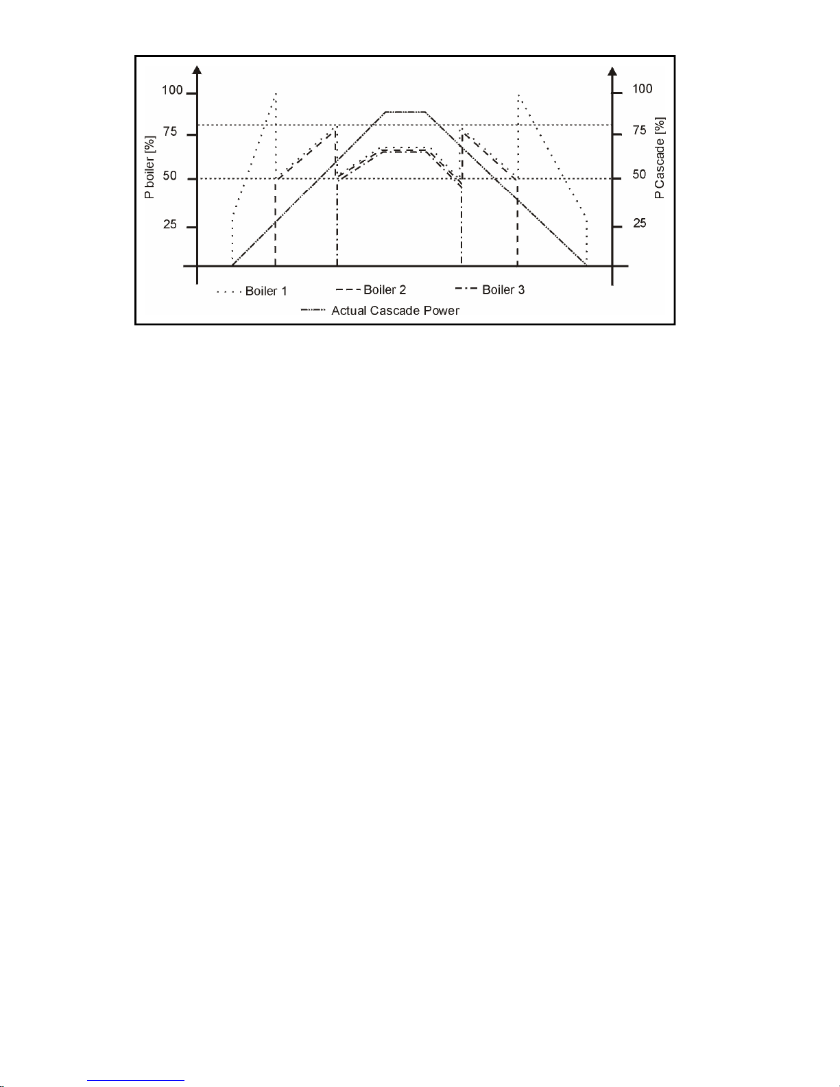
Figure 8.5.2.4.1- Dividing cascade power over 3 boilers
8.5.2.4 Managing the Cascade
The cascade divides the power over all identical connected boilers by programming the Master with the following
information:
• Actual power that the cascade needs based upon the Outside temperature and desired heat curve (when
an outside sensor is connected), and the User temperature setting for the thermostat input.
• Maximum Power (P
max
) that each boiler connected to the cascade can provide.
• Switching Up Power (P
up
) determines when the next boiler should be turned on if the other boilers run at
this power or higher.
• Switching Down Power (P
down
) determines when the last boiler should be turned off if all boilers run at this
power or less.
• Minimum Power (P
min
) that each boiler connected to the cascade, can at least provide.
• Time delay switching on & off a boiler.
8.5.2.4.1 Example of 3 boiler cascade
When there is a demand for heat, the first boiler ignites and provides as much power as the cascade demands.
When the cascade power increases to a point above P
up,
the next boiler ignites and the total cascade power is
divided between the firing boilers. When all boilers in the cascade are on and the cascade power increases more,
all boilers will provide more power until they reach their maximum outputs. When the cascade power decreases,
and the power of each boiler becomes less than P
down
, then the last boiler switched on is switched off and the
power divided between the firing boilers - see figure 8.5.2.4.1
8.5.2.4.2 Boiler switching On/Off
The description above is theoretical as when a boiler is switched on and the new divided power for firing boilers is
set below P
down
, it is unacceptable that a boiler is switched off immediately. Therefore to correct this, the divided
power should be higher than P
down
, before a boiler is switched off when the divided power is less than P
down
.
However, if the divided power won’t increase until it reaches P
down
, the total power of the cascade will decrease, a
boiler will be switched off as soon as the divided power reaches P
min.
Similarly,if a boiler is switched off and the
new divided power is less than P
up
,it would be unacceptable for a boiler to switch on immediately. Therefore to
correct this, the divided power should be less than P
up
before another boiler is turned on. If however the divided
power reaches P
max
, the next boiler should be turned on.
For example - suppose:
P
max
= 100%, Pup = 80%, P
down
= 60%, P
min
= 50%. One boiler is on and the power needed
by the cascade is increasing.
As soon as the divided power reaches 80% the next boiler may be switched on, but it won’t,
because the new divided power will be less than P
min
. 1 boiler on 80% = 2 boilers on 40%
(<50%) In this case the divided power will rise until P
max
, before the second boiler ignites.
1 boiler on 100% = 2 boilers on 50%. When in this example P
down
= 60%, the first boiler will
stay on 100% and the second boiler would switch on as soon as the total power reaches
120% (2 * P
min
).
Page 29

HAMWORTHY HEATING LTD
24
PUREWELL VariHeat he
500001155/F
Similarly, if 2 boilers are on and providing less power than P
down
(2 * 60 = 120%), the 2 boilers will stay on and
modulate further down until the divided power reaches P
min
(or the divided power <= 100% for 1 boiler)
8.5.2.4.3 Blocking timer
When a boiler is switched ON, a ‘blocking off’ timer prevents the boiler from immediately switching OFF. Within
this time, another boiler can switch ON, but a boiler can only switch OFF when the timer has expired. Similarly,
when a boiler is switched OFF, a ‘blocking on’ timer prevents the boiler from immediately switching ON. Again
within this time, another boiler can switch OFF, but a boiler can only switch ON when the timer has expired.
These rules are ONLY overridden when the power of the cascade becomes 0 (eg. open circuit on Remote On/
Off). In this situation all boilers will be switched OFF regardless of ’blocking timer’ settings.
8.5.2.5 Control of Cascade (Primary) Pump
When a primary pump is used, it must be connected to the Master. By setting the relevant parameter, it is
possible to control the primary pump as follows:
Pump runs continuously, even with no heat demand, or
Pump Off. Normally this is used when the Primary pump is under external control, or
Pump runs according to the heat demand and switches Off after the pump overrun time has elapsed.
Frost protection of the Primary Pump is not provided by the Master.
8.5.3 Boiler Management System
This mode of operation relates to a 0~10V dc control signal from a BMS to individual boiler modules, and by
setting the relevant parameter, the level of modulation is determined by the control signal, with only the Frost
Protection function remaining active in the boiler control. Two modes of control are possible;
Temperature control - the modulation is a function of the setpoint temperature.
Power control - the modulation is a function of the determined power requirement of
the cascade.
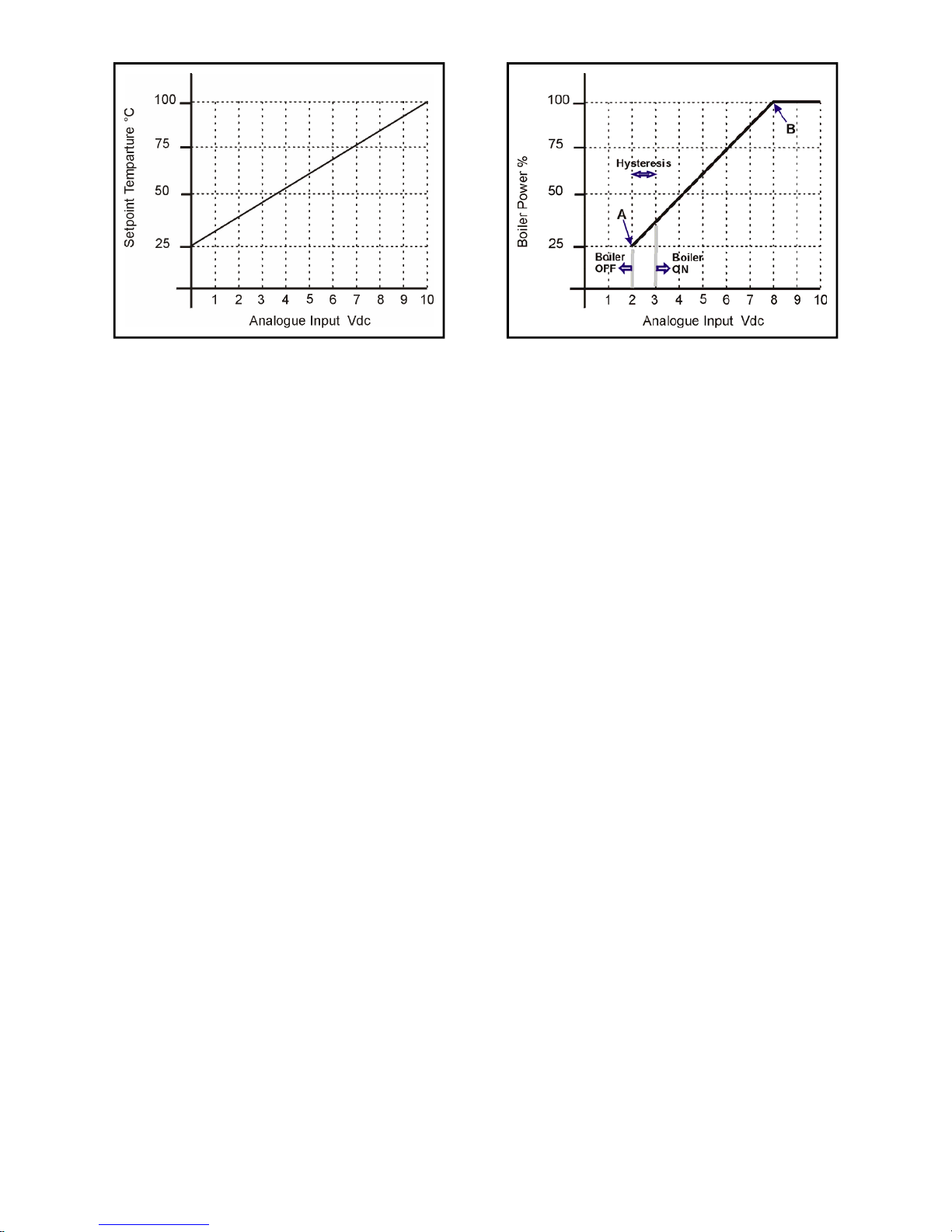
8.5.3.1 Flow Temperature Control (BMS)
The analogue input signal is translated to a setpoint for the flow temperature. Translation is done by setting the
relevant parameters according to a linear line between 0-10V and a temperature range between 0-100°C.
( Maximum flow temperature is factory set to 85°C ).
When the Remote On/Off input is open circuit, the burner stops and will start again when the Remote On/Off
circuit is closed.
8.5.3.2 Power Control (BMS)
The analogue signal is translated to a setpoint for the combustion fan speed (boiler input) by setting the relevant
parameters according to a linear line between points A & B - see Figure 8.5.3.2
When the input voltage is less than A, the burner stops. When the input voltage is higher than A + Hysteresis, the
burner starts. Should the flow temperature exceed the setpoint + it’s Offset, the heat demand is ‘blocked’ and the
anti-cycling timer starts. The ‘block’ is removed as soon as the flow temperature has dropped 10°C and a start will
resume when the anti-cycling timer has expired.
Page 30
HAMWORTHY HEATING LTD
25
PUREWELL VariHeat he
500001155/F
Figure 8.5.3.2 - Power Control Figure 8.5.3.1 - Flow Temperature Control
8.5.4 Central Heating Program
To activate this mode of demand, the relevant parameter must be set to Remote On/Off or Switched Live On/Off.
The central heating demand is detected when the Room Thermostat or Switched Live input closes. If an outside
sensor is fitted, the water temperature setpoint depends on the outside sensor value and the selected heating
curve ( to be set during commissioning).
Modulation during this mode of operation is based upon the measurement of flow sensor S1. The selected heating curve will determine the control setpoint. The user can limit the maximum setpoint.
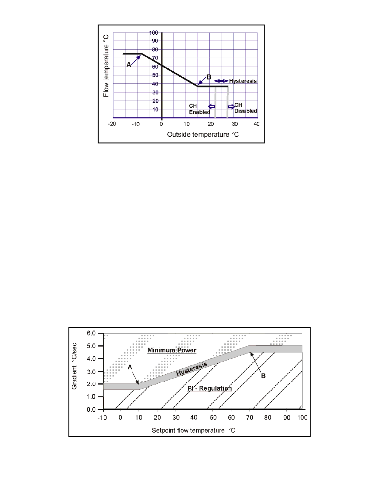
If the outside sensor is not connected, the setpoint is determined by the user.
If the outside air temperature exceeds 32°C the demand is switched OFF, and will be re-instated when the outside
temperature has dropped by the hysteresis setting –see figure 8.5.4.
As soon as the flow temperature exceeds the setpoint by the hysteresis value, the burner will switch OFF, the
pump will continue to run and the anti-cycling timer will start. As soon as the flow temperature has dropped below
the hysteresis value and the anti-cycling timer has elapsed, the burner will switch ON.
The regulation is based upon PI -control, but the maximum capacity of the boiler can be limited by step modulation - refer to section 8.5.7.3.
8.5.5 Frost Protection
Individual boilers are capable of two stage frost protection by setting the relevant parameters.
If the return temperature (sensor S2) drops below the first level protection temperature, the pump is activated. If
the temperature continues to fall below second level protection temperature, the burner is switched ON and the
fan speed is held at minimum firing rate. The pump and the burner remain ON until the temperature rises above
the temperature On Offset.
Should an outside sensor be fitted, by setting the relevant parameters, the pump is switched ON if the outside
temperature is below the minimum frost setting, and it will switch OFF outside of the Hysteresis band.
Should the boiler be switched OFF on the display screen, the frost protection function is still active.
Note: - Frost protection is only available on the Shunt Pump.
8.5.6 Stand-by
Logging data - the control will log data to provide information for both User and Service Engineer. This logged
data can be used to correct an error or block and consists of:
• Total gas consumption
• Running hours, with power equal to or less than 50% of its maximum setting.
• Running hours with power greater than 50% of its maximum setting.
• Total ignition attempts
• Fault ignition
• Last 10 errors/blocks
Page 31
HAMWORTHY HEATING LTD
26
PUREWELL VariHeat he
500001155/F
8.5.7 Special Boiler Functions
8.5.7.1 Anti-cycling
This function is used to limit the switching ON of the boiler in the case of poor heating system design or during
instances of low demand. The anti-cycling function can block a heat demand for a specific time by setting the relevant parameter and is enabled as soon as the block is instigated due to excessive flow temperature. When enabled, any further demands for heat will be blocked and displayed on the screen.
When the heat demand is blocked due to excessive flow temperature and as a result, the flow temperature drops
too quickly during the anti-cycle time, the block can be released before the pre-set time if the return temperature
has dropped by at least the offset based on the return temperature at the start of the block.
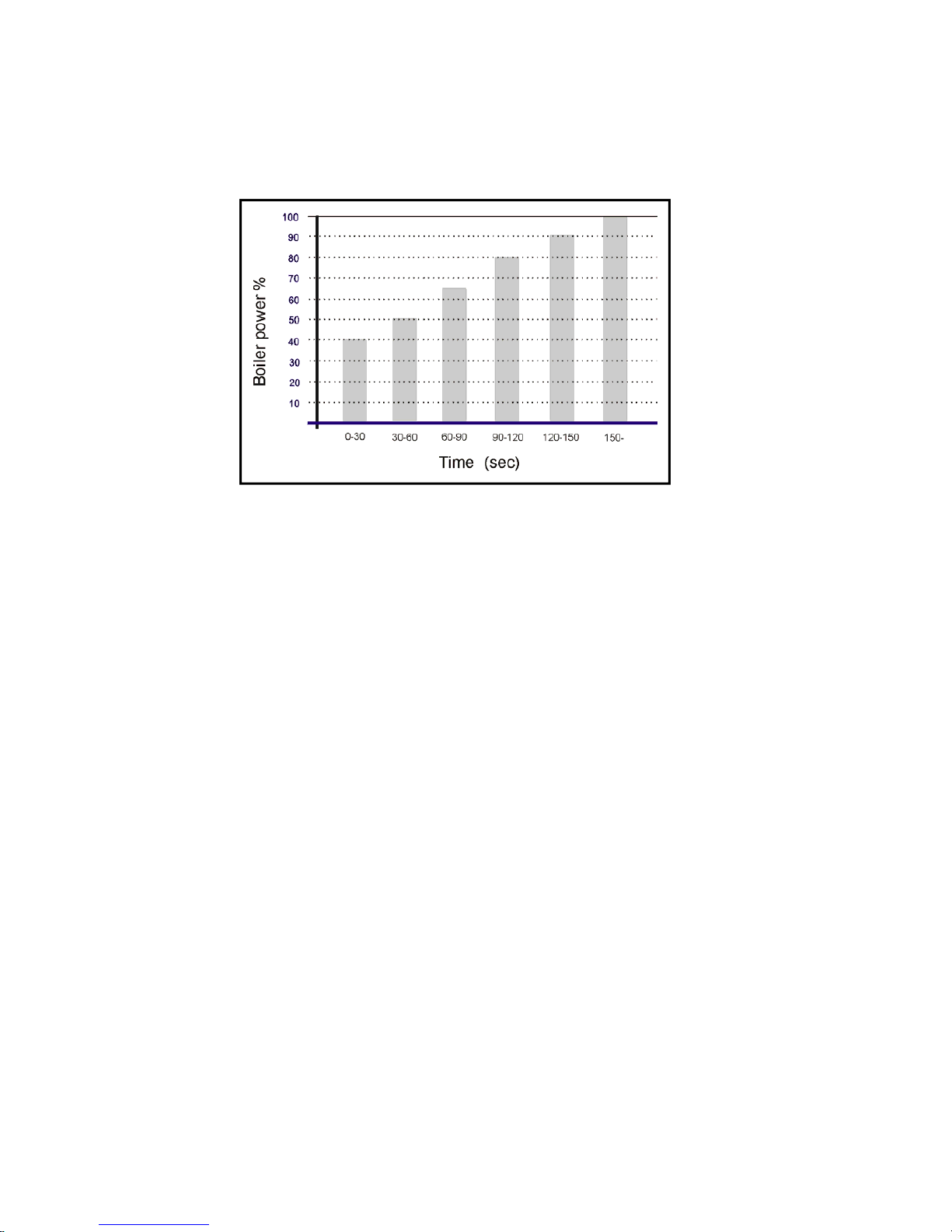
8.5.7.2 Control of flow temperature gradient.
The flow temperature gradient is activated by the following heat demand:
• BMS based on temperature
• Remote On/Off
After switching ON the boiler, if the flow temperature rises too fast (gradient of the flow temperature too high), the
control will set the fan speed to the minimum firing rate. Normally the PI - control should cope with this problem,
but this function will prevent overshoot of the flow temperature when almost no power is required. The maximum
gradient allowable will vary with the actual water temperature reading such that a lower maximum is allowed as
the flow temperature set point is approached - see figure 8.5.7.2 .
Below the Hysteresis line, the fan speed control is based on the PI– regulation. Above the Hysteresis line, the fan
speed is set to its minimum.
The gradient function is determined by points A & B, by setting the relevant parameters.
Figure 8.5.4 - CH heat curve
Figure 8.5.7.2 - Control of flow temperature gradient
Page 32
HAMWORTHY HEATING LTD
27
PUREWELL VariHeat he
500001155/F
8.5.7.3 Step Modulation
This function is particularly effective in avoiding too many firing cycles where the boiler power is relatively high
compared to the minimum heat load. By setting the relevant parameters, as soon as the CH demand is active,
step modulation begins. When in operation, the step is increased over time. The duration of each step, as well as
the power corresponding with each step, determines the rate of increase / decrease in the boiler power.
Note:- the sum of all individual time steps may not exceed 109 minutes.
Figure 8.5.7.3 - Step modulation control
8.5.7.4 Monitoring On/Off ratio remote control On/Off input
This monitoring function provides information about the number of On/Off cycles of the Remote On/Off input. This
can indicate a poor controls philosophy. By setting the relevant parameters, the details will be logged and the
message “BLR: Min CH Cycl” will be shown on the display. This message will be removed automatically as soon
as the time between successive heat demands, within the last time frame, is higher than the minimum cycle time.
8.5.7.5 Blocking Inputs
The BIC 930 control is designed with the ability to programme each input function, open or closed circuit.
Operation of the device on the input (combustion chamber pressure switch or low gas pressure switch), will result
in a block on all heat demands, with corresponding message on the display screen.
8.5.7.6 Fan Speed Control
The fan will modulate to the setpoint determined by the PI—regulation based on the actual flow temperature.
Proportional bandwidth as well as Integration time can be altered together with fan speed settings, by setting the
relevant parameters.
The modulation is limited by the maximum and minimum fan speed settings.
During pre-purge and ignition, the fan speed is fixed at different levels according to the specific boiler. During post
purge, the fan speed is set to the last fan speed achieved with the boiler firing. When no flame is sensed after
ignition, the fan speed is set to the flue gas purge time.
If the desired fan speed is not reached within a specific time period, the control will block the heat demand with a
corresponding message on the display. The fan speed is considered acceptable as soon as the actual speed is
within 30% of its setpoint.
To avoid problems with flame ionisation during the increase/decrease of fan speed, the slope of the increase/
decrease can be limited. During boiler firing, these limits are more important than non firing fan functions (prepurge etc).
8.6 DATA LOGGING FUNCTIONALITY
8.6.1 Gas Consumption
Gas consumption based on fan speed and gas valve opening is logged from two points. The start point is cleared
just before leaving the factory. The second start point can be cleared by the User or Service Engineer, in both
Page 33

HAMWORTHY HEATING LTD
28
PUREWELL VariHeat he
500001155/F
cases the clearing date and time is logged. It is therefore important that the time and date are set correctly.
Both gas consumption values are accessible from the display or PC tool. The maximum value catered for on the
display is 999,999.9m
3
.
8.6.2 Running Hours
As soon as the boiler starts operation, two timers log the total running hours. One indicates the amount of hours
that the boiler is running at a power level equal to or less than 50% of the maximum output. A second timer logs
the amount of hours that the boiler is running at a power level more than 50% of the maximum output. Both values
are accessible from the display or the PC tool.
8.6.3 Ignition Counters
There are four ignition counters. The first counts total ignition attempts. The second counts total failed ignition
attempts ( i.e. it increases with the failure to measure an ionisation current after an ignition cycle). The third and
the fourth are copies of first and second, but can be reset by the User or Service Engineer. All counters are
accessible from the display or the PC tool.
8.6.4 Servicing Notification
When the boiler control determines that a scheduled service is due, the boiler status display will alternate the
standard status screen with the message “SERVICE DUE”, every 5 seconds. This notification is activated as soon
as one of the following rules are met after installation.
1) The service interval time has expired since the last service.
2) The boiler hours run time has expired since the last service.
3) The boiler operations counter has elapsed.
4) Incorrect parameter (influence of EMC, fault of EEPROM).
As soon as servicing is complete, the Engineer should reset the interval counters from the menu. The interval
counters can be set by the relevant parameters.
8.6.5 Error & Blocking
The last 10 errors and the last 10 blocks, are stored in separate tables, together with the date and time which they
occurred. Both tables are accessible from the display or the PC tool. When the table fills up, the oldest error or
block is removed and replaced by the most recent. When an error occurs, it will index two counters. The first will
be cleared at the factory and the second may be cleared by
the Service Engineer.
8.7 DISPLAY SCREEN
The BIC 930 control is designed to operate with a display, which consists of 6 keys and an LCD backlit 2 * 16
character screen. The display must be connected to the control to ensure correct operation of the boiler. If the
display is disconnected from the control, all heat demands are blocked until the connection is restored.
The control can be switched OFF by pushing the On/Off button (top right on the fascia panel). When turned OFF,
the boiler will not respond to a heat demand other than frost protection, if the appropriate parameters have been
set. In this mode, the boiler is not electrically switched OFF, as power is still available to the control to satisfy post
purging of the fan and pump overrun.
When an actual measured temperature is shown on the display, the temperature reading is an integrated value,
so as to dampen any fluctuations.
As soon as the control enters a ’lockout’ state, the text will flash and the backlight is turned On.
8.7.1 Status Display Readings
The display will show various run mode screens, depending upon the left / right button operation:-
• Boiler and Circulation Pump Status Screen
• Water Temperature Sensor Screen
• Fan Speed and Flame Ionisation Signal Screen
• Remote Control Status Input Screen
• Cascade Status and Cascade Pump Status Screen
A temperature reading is normally shown in °C. By setting the relevant parameter, this can be changed to read °F.
When one of the above screens is showing, pressing the Up / Down key will add a sixth screen showing the
Page 34

HAMWORTHY HEATING LTD
29
PUREWELL VariHeat he
500001155/F
actual setpoint of the CH flow temperature. Subsequent pressing of the Up / Down key will increase / decrease
this
setpoint in 0.5°C increments. After changing the desired setpoint, the On/Off key must be pressed to save the
new setting. If the setting is not saved, the previous setting will become active after the next power down.
8.7.1.1 Boiler and Circulation Pump Operation / Fault Status Screen
This screen will be the default start-up screen, and the control will revert to this screen after 1 minute has elapsed
following the last button to be pressed. Fig 8.7 below shows the various combinations of boiler & circulation pump
Status Description LCD Display
Boiler OFF Boiler is ‘Off’ based on display On/Off button
BLR: OFF
PUMP: OFF
Boiler Standby Boiler is ‘On’ and no heat demand is active
BLR: STANDBY
PUMP: OFF
Pre-Purge Heat demand active
BLR: PRE-PURGE
PUMP: RUN
HSi On Hot Surface Igniter warm up period
BLR: IGNITER ON
PUMP: RUN
Gas Valve On Safety Time period
BLR: GAS VALVE ON
PUMP: RUN
Boiler Normal Run Flame stabilisation and normal modulation control
BLR: RUN 065%RATE
PUMP: RUN
Boiler Post Purge End of a firing or ignition sequence
BLR: POST PURGE
PUMP: RUN
Temperature Overshoot Blocking due to high flow temperatures
BLR: TEMP O/SHOOT
PUMP: O/RUN 05MIN
Low Gas Supply Pressure
Blocking due to low gas supply pressure
BLR: LOW GAS PRES
PUMP: OFF
Flue Blocked Blocking due to blocked flue
BLR: DRAIN BLOCKD
PUMP: OFF
Flame Simulation Lockout due to simulation of the ionisation signal
BLR: FLAME SIMLTN
PUMP: RUN
Fan Fault Lockout due fan speed not being achieved
BLR: FAN FAULT
PUMP: RUN
Ignition Lockout Lockout due to no ionisation signal after ignition attempt
BLR: IGN LOCKOUT
PUMP: RUN
Overheat Lockout due to activated Safety Limit Thermostat
BLR: OVERHEAT
PUMP: RUN
Flow Temperature Sensor Fault
Lockout due to short circuit or interrupted sensor input (S1, S2 or
S3)
BLR: SENSOR FAULT
PUMP: RUN
Anti-cycling
Function
Blocking due to boiler cycle time
BLR: ANTI_CYCLING
PUMP: RUN
Service Mode Heat demand activated by Service Mode
BLR: SERVICE MODE
PUMP: RUN
Remote Control Fault Remote Control On/Off input operating too often. Message flashes.
BLR: REM CTRL FLT
PUMP: RUN
Servicing Notification Scheduled service is due. Message flashes
BLR: SERVICE DUE
PUMP: RUN
Figure 8.7—Display Status Screens
Page 35

HAMWORTHY HEATING LTD
30
PUREWELL VariHeat he
500001155/F
8.7.1.2 Water Temperature Sensor Screen
This screen will appear as soon as the left button is pressed from the ‘Boiler and Circulation Status Screen’.
Should a temperature reading measured be outside the allowable range, the message will show “SENSOR
FAULT”
Status Description LCD Display
Water Temperatures Flow
and Return
Showing flow temperature and return temperature measured by S1 &
S2. Also in brackets ( ) the setpoint of the flow temperature.
FLW:036.5°C(082)
RTN:023.0°C
Figure 8.7.1.2 - Water Temperature Sensor Screen
8.7.1.3 Fan Speed & Flame ionisation Screen
This screen will appear as soon as the left button is pressed twice from the ‘Boiler and Circulation Status Screen’.
The actual fan speed is shown to the nearest 10 rpm. However, when the Service Function is active, and the fan
setpoint has altered, the first line will show the new setpoint for 3 seconds. After which, the actual speed will be
shown
The actual flame signal is shown to the nearest 0.5 µA
Status Description LCD Display
Fan Speed & Flame
Ionisation Signal
Showing actual fan speed and ionisation current
FAN SPD:04320rpm
FLAME SIG:03.5 µA
Figure 8.7.1.3 - Fan Speed & Flame ionisation Screen
Status Description LCD Display
Remote Control On/Off
Input
Showing the Remote Control Input & the Analogue Input signals
REMOTE I/O: OFF
ANALOG SIG:00.0V
8.7.1.4 Remote Control Input Status Screen
This screen will appear as soon as the left button is pressed three times from the ‘Boiler and Circulation Status
Screen’.
Figure 8.7.1.4 - Remote Control Input Status Screen
8.7.1.5 Cascade and Cascade Pump Status Screen
This screen will appear as soon as the left button is pressed four times from the ‘Boiler and Circulation Status
Screen’ and the controller is configured as the Cascade Master. This screen will provide information about the
status of the cascade and it’s pump.
Status Description LCD Display
Cascade OFF Cascade is ‘Off’ based on display On/Off button
CAS: OFF
PUMP: OFF
Cascade Standby Cascade is ‘On’ and no heat demand is active
CAS: STANDBY
PUMP: OFF
Cascade No Slaves The cascade Master is unable to locate Slaves.
CAS: NO SLAVES
PUMP: OFF
Cascade ON
The cascade is active, with the cascade actual temperature and its
setpoint.
CAS:ONS4 +setpoint°C
PUMP: ON
Cascade without sensor
S4
The cascade sensor S4, is not present. All connected slaves will get
maximum power and calculated cascade setpoint.
CAS:S4NOT PRESENT
PUMP: ON
Figure 8.7.1.5 - Cascade Status Screen
Page 36
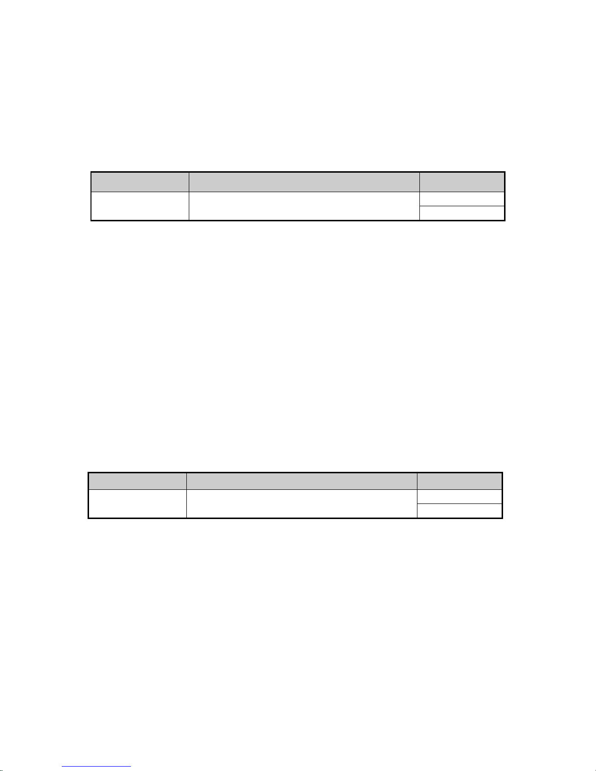
HAMWORTHY HEATING LTD
31
PUREWELL VariHeat he
500001155/F
8.7.1.6 - Cascade Information Screen
This screen will appear as soon as the left button is pressed five times from the ‘Boiler & Circulation Status
Screen’ and the controller is configured as a Cascade Master.
The first line will give information about the power given to each activated Slave followed by the total power controlled by the Cascade. This second value can reach more than 100%, when for instance 6 boilers are connected,
the total power of the cascade is set to 600%.
The second line will give information about connected Slaves. The first number is the address of the Slave (or
Master) which has the highest priority. When a “-” is shown, the corresponding number of that Slave which is not
connected, or is ‘locked out’, is not available to the Cascade. When the number is flashing, that relevant Slave or
Master, is participating in the heat demand.
Example: - a cascade configured with 6 boilers (addressed 0,1,2,4,5,7), the actual power is 65% and currently 3
boilers are turned on, boiler number 5 has the highest priority.
Status Description LCD Display
Cascade ON at 65% of a
max of 600%
3 out of 6 boilers are turned On. Highest priority is set to boiler ‘5’.
Boilers 6 & 3 are not connected or are in Lockout.
CAS POW:065%600%
PRESENT:5-7 0 1 2-4
Figure 8.7.1.6 - Cascade Information Screen
8.7.2 Controlled Programming of Parameters from the Display
With the display, several parameter settings can be changed. There are three levels of access to the parameters:
• ‘User’ level. Parameters accessible by the User, are protected with a 4 digit code (default 0303), which is
programmable by the User. To enter the ‘Access Code’, the User should press and hold the Exit key for 3
seconds.
• ‘Engineer’ level. Parameters accessible by the Engineer, are protected with a 4 digit code (refer to Hamwor-
thy Heating Ltd). To enter the ‘Access Code’, the User should press and hold the Exit key for 3 seconds.
• ‘Factory’ level. Some parameters are only accessible by the manufacturer. To access these parameters, a
PC tool is required.
8.7.2.1 Code Input Menu
This screen allows access to the above security levels, such that parameters can be changed. After pressing the
Exit button for 3 seconds, the display shows a four digit sequence zeros. After entering the security number press
enter again.
The code can be entered by moving to each digit in the sequence using the ‘left / right’ keys. A flashing digit indicates the position in the sequence to be entered. The ‘up / down’ keys can be used to increase or decrease the
digit value.
After selecting the correct code (User or Engineer), the Enter key must be pressed. If the correct code has been
entered, the display confirms for one second the security level entered, before going into the options menu in that
level. When an incorrect code is put in , the display will return to the normal status screen.
Status Description LCD Display
Code Input Menu Code Input Menu accessed by User
ENTER MENU CODE
0303
Figure 8.7.2.1 - Access Status Screen
8.7.2.2 Main Menu (Within The Security Level Chosen)
The main menu is shown as a list which can be scrolled by pressing the ‘Up or Down’ keys. Within the list are
items which are accessible by entering the appropriate code.
The currently selected item on the list is identified by the ‘►’ symbol. Pressing the ‘Enter’ key will select a submenu relevant to the currently selected item. Only selected items relevant to the code entered are displayed. To
leave the main menu and return to the ‘Boiler and Pump Status Screen’, press the ‘Exit’ key.
After selection of a menu item, the display will show the description and an alternating menu number. By pressing
the ‘Up / Down’ key the specific number can be selected. The value of that item will be shown as that item number
is selected by pressing the ‘On/Off’ key. At this point the ‘Up / Down keys will change the value of the selected
item. To save the new value, the Enter key must be pressed, and the value will be stored in the EEPROM, before
returning to the ‘Boiler and Pump Status Screen’. Should additional parameters require adjustment, by pressing
the ‘Exit’ key after changing the value of the item, the screen will return to the ‘Main Menu’. Once all values have
been changed, the Enter key can be pressed to return to Boiler and Pump Status Screen’.
Should a changed value not be stored in the EEPROM, the control will revert to the original setting at the end of
the current heat demand.
Page 37
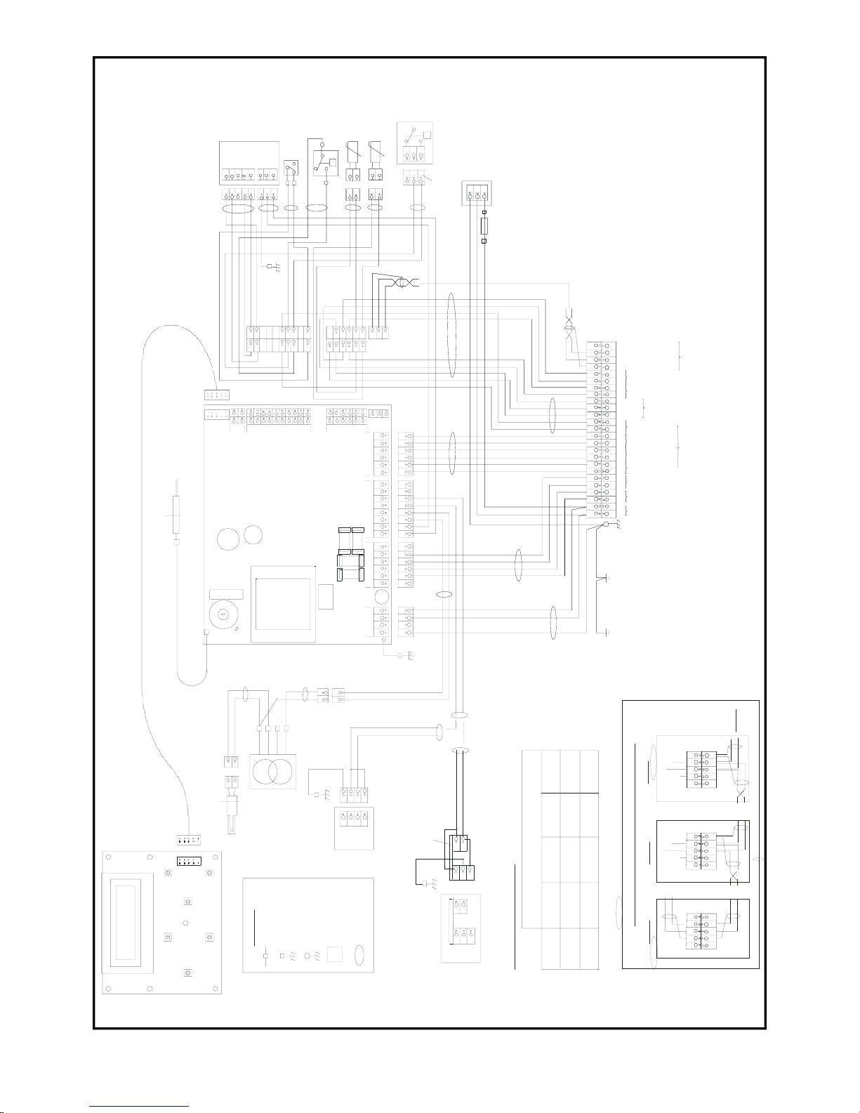
HAMWORTHY HEATING LTD
32
PUREWELL VariHeat he
500001155/F
2
P
3
1
2
3
3
1
GREY PLUG
1
2
3
3
1
2
GND
N
230V
1
2
4
5
1
2
4
5
+V
HA L L
PVM
- V
DC SERVO FAN
S EE TAB LE 1
LOW GAS PRESSURE SWITCH
FO R PART NO.SEE TABLE A
RED
-T
22
1
1
P
2 N O
1 NC
3 COM
1
2
C
NO FL UE PRES SU RE SW ITC H
HHL PART 53 390 13 34
B
A
2
1
1
BLUE
BRO W N
RED
GND
N
230V
+V
HA L L
PVM
- V
G/Y
BLU E
BLU E
RED
BROWN
BRO WN
BLU E
BLACK
-T
P
NC SAFETY L IMIT THERMOSTAT
HH L PART 5339011 79
1
2
C
GND 2
B
A
2
RETU RN S ENSOR - BLUE DOT
HHL PART 533901431
FLOW SENSOR - RED DOT
HHL PA R T 53 3 90 143 1
BLUE
BLU E
13
3
BRO W N
BLU E
G/Y
RE D
IE C MAINS OUT LET
E
L
N
SCR EEN
BLU E
RED
RED
BLACK
BLU E
BROWN
RED
BLUE
RED
BROWN
BL ACK
WHITE
BLU E
RED
53 390 303 6
533901497
53 39 0 13 7 6
53 390 303 7
GAS PRESS
SWITCH
DC SER VO
FAN
563902248
563902 244
WIRING LOOM GAS VALVE
HHL PART NUMBER
PV105 /12 5he
TA BLE A COMPONENT SPECIFICATION
PV65/85h e
BOILER
MODEL
1
GR OUND
M AINS SUPPLY
PRIM ARY PU MP
3
2
32
N
REMOTE ON/O FF
4-20mA
0-1 0V
OU TP UT SIGNAL
OUTSIDE TEMP SENSOR
CASC AD E T EM P SENSO R
17
16
15
14
17
1615
14
20
20
X6
X7
X5
20
191514
11
10
9
541
BRO W N
B
A
1
2
3
4
5
6
1
2
3
7
8
9
10
11
54
25
22
21
98
26
24
23
19
18
13
12
11
10
76
SHU NT PUMP
5
4
5
612
3
4
E
BOI LE R PE
SLAVE
BLU E (N )
BRO WN 11 5 V AC
G/Y
GND 1
GND
23 0 V
N
3
2
1
1
3
2
GAS VALVE
SEE TABLE A
2
2
1
1
BROWN 230 V AC
BLAC K
BLUE (N )
G/Y
BLACK
BROWN
BLUE
PLATE
ON TE RMIN AL
TER MI N A L
M5 RIN G
TW ISTED PAIR (SHIELDED)
BLACK
BLU E
BROWN
WHI TE
GREY
BLU E
3
4
1
2
341
2
7
8
7
8
3
4
5
6
34
5
6
34
1
2
5
6
3
4
1
2
5
6
X1
X2
X4
X3
11
7
FL AME PR OBE W IR E - H HL PART 533901490
25
22
21
98
26
24
23
19
18
13
12
11
10
76
LOCKOUT
N ORM A L RU N
OVERHEAT
SLAVE SI GNA L
MULTI -CORE C ABLE
SLAV E S CR EE N OU T
H. S.I PR OB E
-HHL PART 563801016
GROUND
TE R MIN A L CO NN E C TO R
BRAC KE T
CONTROLS
TAB ON
GND 2 -
BOILER COMPONENT
EA RT H CO NNECTOR
TERMINAL CONNECTOR
SY MBOL KE Y
RIBBON CABLE/ CONNE CTOR - HHL PART 563901416
MASTER SCREEN OUT
FU NCTIONS
CASC AD E
/ ALAR M S IG NAL S
CONTACT
VOLT FREE
BL UE
BROWN
L
SCREEN
B OIL ER CONTROLLER
FOR H HL PART NO.SEE PAGE 38
X5
FLAME PROBE - HHL PART 53 3805015
6
12
9
1
1
X6
X8
X7
X1 1
533704003
533925004
F USE 2A
D5 x 20 FUSE - HHL PART 533922002
FUSE HOLDER - HHL PART 53392201 0
2
1
2
1
H.S.I TRANSFORMER
HHL PA R T 53 39 0 14 41
H.S.I EXTEN SIO N CABL E
HHL PART 563902245
143
BRO W N ( ~ 23 0V )
BLUE
(N)
RED(~120V)
G/Y
GND 1
GND
2 30V
N
WIRING FOR GAS VALVE HHL No.533903037
BLACK MOL DED PLUG
230V
N
WIRING FOR GAS VALVE HHL No. 533903036
EITHER
BRO W N
BLU E
G/Y
E
L
N
RED
BLACK
BLU E
BROWN
RED
BLUE
RED
1
GR OUND
MAINS SUPPLY
PRIM ARY PU MP
3
2
32
N
REMOTE ON/O FF
4-20mA
0-1 0V
OU TP UT SIGNAL
OUTSIDE TEMP SENSOR
CASC AD E T EM P SENSO R
17
16
15
14
17
1615
14
20
20
54
25
22
21
98
26
24
23
19
18
13
12
11
10
76
SHU NT PUMP
5
4
E
BOI LE R PE
SLAVE
G/Y
BLACK
BROWN
BLUE
PLATE
ON TE RMIN AL
TER MI N A L
M5 RIN G
TW ISTED PAIR (SHIELDED)
BLACK
BLU E
BROWN
WHI TE
GREY
25
22
21
98
26
24
23
19
18
13
12
11
10
76
LOCKOUT
N ORM A L RU N
OVERHEAT
SLAVE SI GNA L
SLAV E S CR EE N OU T
GROUND
MASTER SCREEN OUT
FU NCTIONS
CASC AD E
/ ALAR M S IG NAL S
CONTACT
VOLT FREE
BL UE
BROWN
L
SCREEN
F USE 2A
D5 x 20 FUSE - HHL PART 533922002
FUSE HOLDER - HHL PART 53392201 0
26
25
23
26
25
24
23
24
26
25
23
26
25
24
23
RED
BLU E
24
SCREEN
RE D
BLUE
26
2523
26
25
24
23
24
RED
BLUE
MASTER
SLAVE 1
SLAV E X
TERMINAL CONNECTI ON RS -48 3 BU S C ABLE - HHL PART 563 90 223 6
SLAVE Y
Figure 9.0 Boiler Wiring Schematic
Page 38

HAMWORTHY HEATING LTD
33
PUREWELL VariHeat he
500001155/F
9.0 FAULT FINDING
The Purewell VariHeat he boiler is equipped with full self diagnostic fault indication, which is displayed on the
screen - refer to section 8.7 - Controls Operation.
Should a fault occur which cannot be reset, or a fault repeatedly occurs, contact Hamworthy Heating for
assistance. Do not continue to operate or use the boiler as this may cause damage to the boiler or
controls.
9.1 Safety Features Summary
9.1.1 Safety Temperature Limiter
The electronic control thermostat has several safety levels built in such that a controlled shutdown should occur
before the safety temperature limiter is activated. Should these safety levels be overridden (say external pump
overrun failure after shutdown) the safety temperature limiter will trip initiating a boiler shutdown, preventing the
boiler from firing.
Should the control thermostat fail, causing an overheat condition, the safety temperature limiter will trip thus creating an
immediate shutdown regardless of firing mode. An overheat message on the controls fascia will indicate that this
condition has occurred. The safety temperature limiter is reset by depressing the reset pin protruding through the hole
near the centre of the controls fascia. If, after pushing the pin in, the display screen does not reset and the boiler does not
light up, it could be that the boiler is still too hot, i.e. the control thermostat has not re-set. An investigation should be
carried out to ascertain the reason for the overheating. An obvious reason would be too low a water flow rate through the
boiler.
The flame is under constant supervision by the burner logic controller. This is accomplished by measuring the flame's
ability to rectify an AC current. If the flame diminishes for whatever reason and the rectified current drops below the
controllers minimum (1.2µA DC), the controller will make 1 attempt to re-light. If this attempt is unsuccessful a non-volatile
lockout occurs which requires a manual re-set (‘on/off button situated on the controls fascia) to re-start the control
sequence.
If the boiler continues to lockout, then an investigation must be made to ascertain the cause - refer to section 9.3 below.
9.2 Fault Finding Procedures
General error messages are detailed in figure 8.7 to assist with fault finding . If the boiler still cannot be operated
satisfactorily after following the instructions, consult your local office of Hamworthy Heating for assistance.
9.3 Possible Causes of Boiler Lockout
1) Ignition failure due to faulty igniter.
2) Ignition failure due to faulty gas valve.
3) No ignition due to faulty controller.
4) Ignition failure due to faulty flame probe or sensing circuit.
9.4 Conditions ‘Blocking’ Operation of Boiler
1) Condensate trap blocked (differential pressure switch activated).
2) No or low gas supply pressure.
10.0 SERVICING
A competent person registered for working on non domestic gas appliances should check and ensure that the
flue, its support and terminal, the ventilation to the boiler house, safety valve, condensate trap, drain, water
filter if fitted, pressure gauge etc., are in a serviceable and working condition, and still comply with the
relevant standards and codes of practice - see Section 4 & Appendices
10.1 Regular servicing is recommended, preferably by a Hamworthy appointed person, and at least annually, to
ensure trouble free operation.
For the Purewell VariHeat he, Hamworthy would recommend an additional 6 monthly examination following
commissioning, acknowledging site conditions and running hours.
Although cleaning of flueways may not be necessary on a yearly basis inspection of the flueways must be undertaken
annually and it is important that all controls and safety features are checked for correct operation.
NOTE! Measuring flue gas CO
2
and gas temperatures will give an indication of the state of the boiler flueways and
Page 39

HAMWORTHY HEATING LTD
34
PUREWELL VariHeat he
500001155/F
waterways. Results should be compared with previously measured values to establish possible loss of efficiency.
Should remedial work be carried out on a boiler within a bank of boilers, then the non-firing boiler must be
electrically isolated so as to prevent accidental operation., in the event that the installation is required for
ongoing heating requirements.
10.2 The procedure detailed relates to a single boiler and must be carried out on all boilers within the bank of boilers.
Before servicing the boiler, the following procedure must be carried out: -
WARNING: Isolate the electrical supply and turn off the gas isolating valve to the boiler module being
serviced.
1) To remove the front casing door, turn the 1/4 turn screws securing the fascia moulding a 1/4 turn clockwise. Pivot
the fascia moulding about it’s bottom edge to 45 degrees and lift off. Store in a safe place to avoid damage. rotate the
two 1/4 turn screws securing the front casing door a 1/4 turn and lift off from the front brace. Rotate the two 1/4 turn
screws fixing the top panel to loosen and slide the panel in the direction of the rear of the boiler to disengage from the
securing pins on the back panel.
2) Turn off gas service cock.
3) Disconnect the gas valve plug assembly from the gas valve and disconnect the low gas pressure switch plug.
Disconnect the gas valve inlet flange from the gas valve. Disconnect the 3 & 5 way electrical plugs from the fan
body.
4) Disconnect igniter and probe leads. Disconnect the fan/gas valve assembly from the burner body by removing
the 4 M8 nuts securing the transition duct to the burner. Carefully place the fan/gas valve to one side.
5) Loosen the 4 - M8 nuts securing the burner clamping flange to the tie rods and carefully remove the clamp.
The burner assembly can be removed by withdrawing upwards. Check condition of igniter assembly and probe for
damage. Clean as required. Check burner surface and clean using a soft brush if required (if possible use
compressed air to blow out the dust inside the burner. A damaged burner must be replaced.
6) Examine the non return valve located in the fan/burner duct for free operation and integrity of the foam seal.
Replace if necessary.
7) Remove the screws securing the gas valve and discharge tube assembly to the air inlet box and carefully place
to one side.
8) Inspect the fan impellor and clean using a soft brush and compressed air.
10.3 The boiler flueways can now be cleaned as follows:-
Prior to cleaning the flueways, the inspection panel secured to the front base of the boiler must be
removed.
1) Using a suitable brush, clean the vertical fins on the castings below the burner.
2) Using a torch, inspect the sump below the cast iron sections and clean. Any loose debris can be removed
from the sump through the inspection panel.
4) Re-assemble the boiler in the reverse order to that shown above. Ensure a new seal is fitted to the top
casting / burner joint to maintain a gas tight seal, (see spares list). Ensure that a new seal is fitted to the
inspection panel. The boiler’s operation may be affected if these seals are do not form a gas tight joint.
5) Re-assemble the burner and clamp plate to the top casting and secure using the M8 nuts and tie rods,
ensuring that the joint is sound. Assemble the gas valve, fan, transition duct using new gaskets. Refit the gas
inlet flange to the gas valve using a new ‘O’ ring. Check all gas connections are tightened securely before
opening the gas service cock. Re-connect electrical connections. Switch on the electricity supply and re-light
the boiler following the procedure detailed in section 7.3.
6) Take exhaust gas readings and compare with section 7.4. Ensure no gas leaks are evident from the gas
connections, refer to section 7.1 for procedure. Check thermostat settings and adjust if required.
Page 40

HAMWORTHY HEATING LTD
35
PUREWELL VariHeat he
500001155/F
11.0 REPLACEMENT OF FAILED COMPONENTS
There are a number of components listed below which can be replaced simply and quickly by following the
given procedure. In each case carry out the appropriate part of the commissioning procedure & check the
operation of each component replaced. See Section 7.3:Commissioning and Testing
NOTE: Isolate electrical supply to the boiler and turn off the gas supply after removing controls cover
and before commencing any servicing or component exchange procedure.
11.1 Igniter and Flame Probe Assembly
Both Ignitor and flame probe are secured in the same manner.
Reference to Figure 11.1 shows position of igniter assembly. To remove assembly disconnect the plug/socket on
the supply lead and remove the screw securing the igniter to the burner front panel. Figure 11.1 shows diagram of
igniter assembly and relevant components. Renew components as required and generally remove any loose
sooty deposits and clean as required. Ensure positions of components are as recommended in Figure 11.1.
11.2 Safety Temperature Limiter (Limit Stat)
With the boiler front cover removed, the Limit Stat is situated on the rear of the control panel fascia bracket to the
left hand side of the main PCB.
Remove the 'push on' spade connections from the temperature limiter body noting position of coloured cables.
Remove plastic cover (if fitted) and unscrew holding nut to detach temperature limiter from housing. Gently feed
the capillary back through the controls bulkhead. Re-set temperature limiter to 95°C. Check the operation of the
device by carefully applying a heat source to the bulb. Re-assemble temperature limiter into controls housing
ensuring correct cable notation. Refer to Figure 9.0.
11.3 Main Gas Valve.
NOTE! Hamworthy Heating strongly recommend that a new gas valve assembly is fitted to ensure safe, reliable
operation of the boiler. The gas valve is supplied as a factory set component & must not be tampered with.
1) Disconnect the gas valve electrical plug and pressure switch plug.
Remove the four socket head screws securing the gas valve inlet flange. Take the weight of the gas valve and
remove the four socket head screws securing the gas valve to the discharge pipe assembly. Withdraw the gas
valve.
2) Always fit new ‘O’ rings to both inlet and outlet when replacing the gas valve.
Always test for gas soundness after replacement parts have been fitted.
Refer to Section 7.1, if necessary for valve integrity check procedure.
3) Re-light the boiler using instructions on the inside of the door. Check for correct operation. If necessary, refer
to Section 7.4 Commissioning the Boiler, for correct procedures.
11.4 Combustion Fan
NOTE! To remove the fan, it is necessary to remove the gas valve and discharge pipe assembly.
1) Disconnect the gas valve plug assembly from the gas valve and pressure switch. Disconnect the gas valve inlet
flange from the gas valve. Disconnect the 3 & 5 way electrical plugs from the fan body.
2) Disconnect the fan/gas valve assembly from the burner body by removing the 4 M8 nuts securing the transition
duct to the burner.
3) Remove the screws securing the gas valve and discharge tube assembly to the air inlet box and carefully place
to one side (PV65he and PV85he Models only).
4) Remove the screws securing the air / gas mixing device to the fan and withdraw the air inlet box, carefully
place to one side (PV65he and PV85he Models only).
5) Remove the screws securing the fan outlet to the burner transition duct. Beware there is a non return valve
fitted between these components.
6) Re-assemble in reverse order using new gaskets where appropriate. After assembly and prior to re-fitting the
assembly to the burner, check for correct and free operation of the non return valve in the burner transition duct.
Page 41
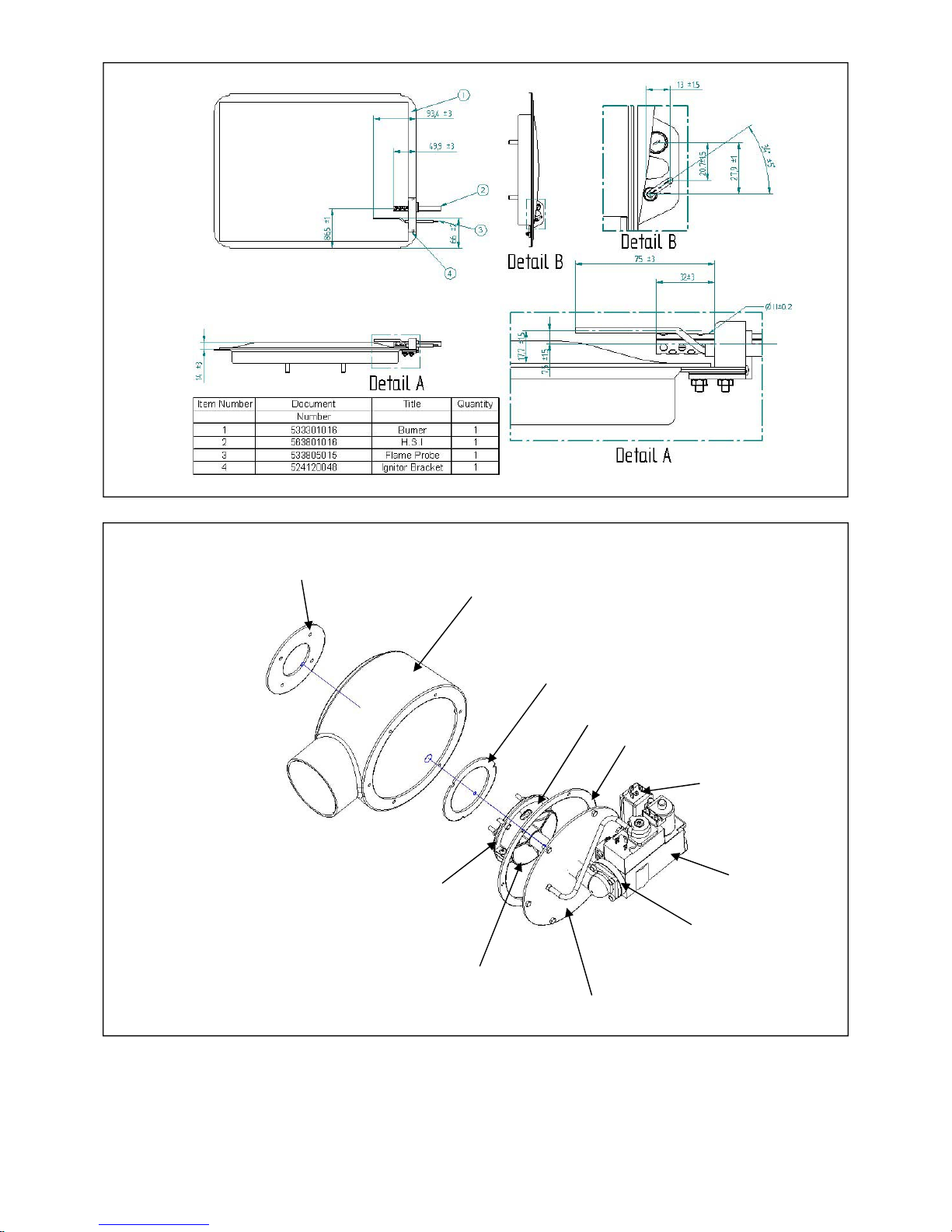
HAMWORTHY HEATING LTD
36
PUREWELL VariHeat he
500001155/F
Figure 11.1 - Hot Surface Igniter and Flame Sensing Probe Positions
Figure 11.2 - Gas Valve Assembly ( model 65 he - 85 he shown for illustration)
531201103
Fan/Airbox Seal
532407002 Airbox
531201104 Venturi Seal
532418003
Venturi Clamp
533001029 Baffle
532418002 Venturi
531201105 Fan/Airbox O/Side Seal
532403148 Closing Plate
531403031 Spacer
533901497 Gas
Pressure Switch
533903037 Gas Valve
Page 42
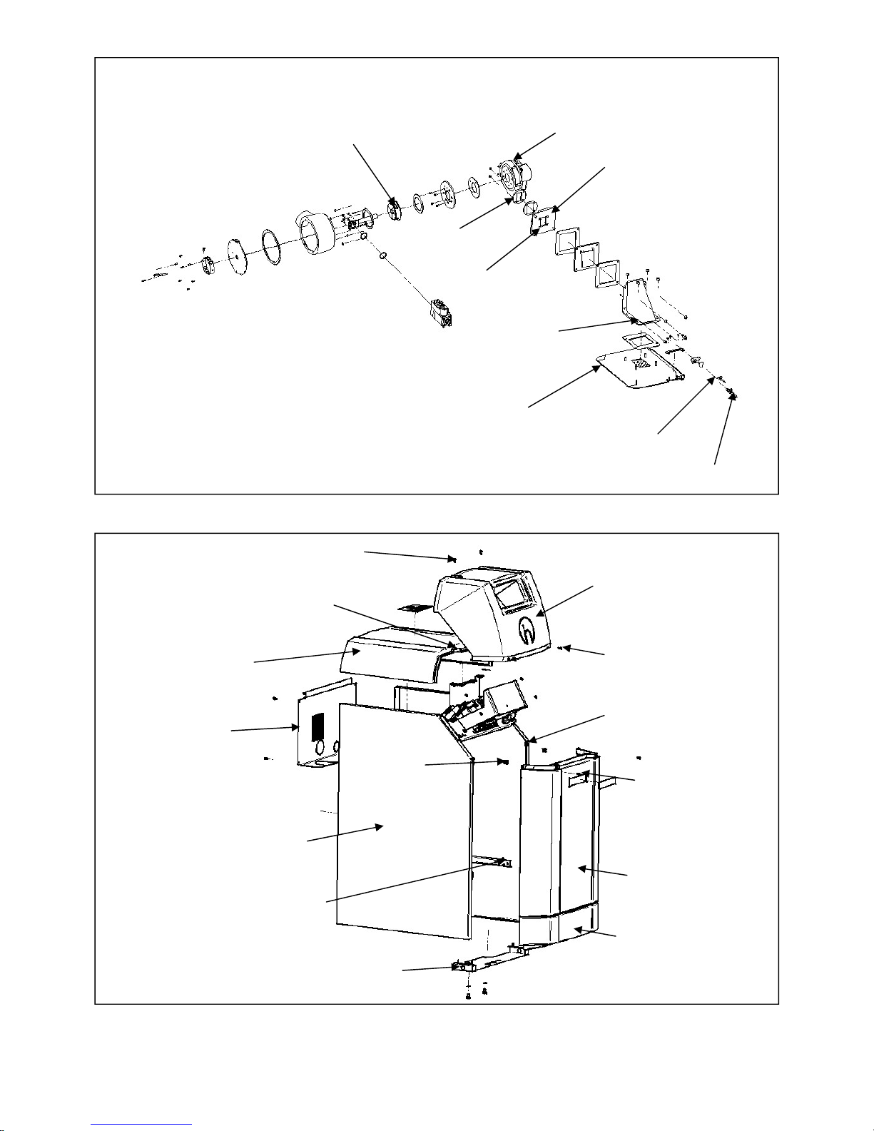
HAMWORTHY HEATING LTD
37
PUREWELL VariHeat he
500001155/F
Figure 11.3 - Combustion Fan Assembly ( model 65 he - 85 he shown for illustration)
Figure 11.4 - Casing Assembly
53301016 Burner
531201123 Burner
Elbow Gasket
563007019 Flapper Valve
531201123 Burner
Elbow Gasket
531201102 Fan
Elbow Seal
RG148 Fan
532418002 Venturi
563801016 HSI
533805015 Flame Probe
530650354 Control Cover
748551010 1/4 Turn Screw
530650352 Front Cover
Molding
530650346 Lower
Front Cover
748551009 1/4 Turn
Receptacle
748551010 1/4
Turn Screw
748551010 1/4 Turn Screw
530650353 Top Cover
748551006 1/4 Turn
Fastner Clip
530650355 Front
Cover Brace
530650348 LHS Panel
(530650347 RHS)
748551001 1/4 Turn Screw
530650351 Side Rail
530650204 Back Panel
Page 43
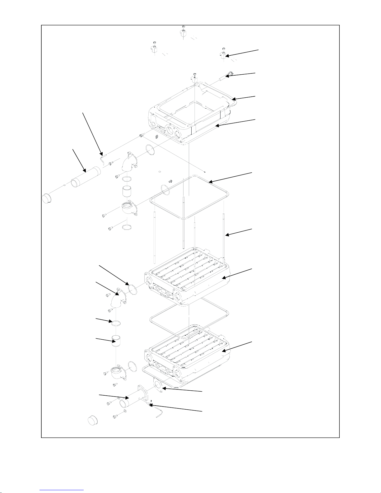
HAMWORTHY HEATING LTD
38
PUREWELL VariHeat he
500001155/F
Figure 11.5 - Heat Exchanger Assembly ( model 65he - 85he shown for illustration)
524120049 Section Clamp
531050013 Thermostat
Pocket
531201121 Burner Gasket
524120042 Combustion
Chamber
531201120 Section Seal
53201204 Tie Rod
524120043 Heat Exchanger
524120045 Heat Exchanger
531050011 R1/4 Sensor Pocket
532403217 Inlet
Water Connection
531201122 Water Connection Gasket
532403166 Tube
742121186 O-Ring
532403167 Elbow
742121238 O-ring
532403214 Outlet
Connection
533901431 10K NTC
Temp Sensor
Page 44

HAMWORTHY HEATING LTD
39
PUREWELL VariHeat he
500001155/F
12.0 RECOMMENDED SPARES
Please Note:- To ensure the correct spare parts are despatched by our spares department, it is imperative that the
complete Boiler/Module/Control Panel Serial Numbers are given. The Boiler and Module Serial Numbers are located on
the Data Plates affixed to the front of the heat exchanger base casting The Electrical Serial Number is located inside the
Control panel on the maximum power rating label. These numbers MUST be quoted when ordering spare parts.
SPARES ITEM PART No.
ELECTRICAL ITEMS
BIC 930 Main PCB - 65 he ............................................................................................................................................533902046
BIC 930 Main PCB - 85 he ............................................................................................................................................533902047
BIC 930 Main PCB - 105 he..........................................................................................................................................533902048
BIC 930 Main PCB - 125 he..........................................................................................................................................533902049
DU 930 Display PCB......................................................................................................................................................533902039
Flow / Return Sensor .....................................................................................................................................................533901431
Temperature Limiter.......................................................................................................................................................533901179
Hot Surface Igniter..........................................................................................................................................................563801016
Flame Sensing Probe ....................................................................................................................................................533805015
T2A 5x20 Fuse ..........................................................................................................................................................533922002
T1.25A 5x20 Fuse..........................................................................................................................................................533922011
T3.25A 5x20 Fuse..........................................................................................................................................................533922005
MECHANICAL ITEMS
Burner..............................................................................................................................................................................533301016
Gas Valve (65 he - 85 he)..............................................................................................................................................533903037
Gas Valve ‘O’ Ring (65 he - 85 he) ...............................................................................................................................531299018
Gas Valve (105 he - 125 he) .........................................................................................................................................533903036
Gas Valve ‘O’ Ring (105 he - 125 he)...........................................................................................................................531299032
Combustion Fan (65 he - 85 he) ...................................................................................................................................533901376
Combustion Fan (105 he - 125 he)...............................................................................................................................533704003
Air Pressure Switch........................................................................................................................................................533901496
Low Gas Pressure Switch (65 he - 85 he)....................................................................................................................533901497
Low Gas Pressure Switch (105 he- 125 he) ................................................................................................................533925004
Set of Gaskets (Routine Service - combustion system)..............................................................................................563605342
Set of Gaskets (Major Service - combustion system plus heat exchanger) ..............................................................563605343
For service or spares please contact :- Hamworthy Heating Limited
Fleets Corner
Poole
Dorset BH17 0HH
Phone Number ............................................................................... 01202 662500
Fax Number..................................................................................... 01202 665111
Service ............................................................................................. 01202 662555
Spares .............................................................................................. 01202 662525
Technical ......................................................................................... 01202 662566
Page 45
HAMWORTHY HEATING LTD
40
PUREWELL VariHeat he
500001155/F
APPENDIX A - GAS DATA
GENERAL DATA
Purewell VariHeat he
BOILER MODEL
Model
65 he 85 he 105 he
Boiler Input (maximum) - kW (Gross)
80.1 107.5 128.0
Boiler Input (maximum) - kW (Nett)
72.1 96.8 118.1
Boiler Output (maximum) 80/60°C - kW
65 85 105
Boiler Output (minimum) - kW 21.5 30.1 33.6
125 he
154.3
139.76
125
39.8
Natural Gas
GAS DATA
Gas Inlet Connection Pipe Thread Size
R1”
Nominal Gas Inlet Pressure - mbar 20
Maximum Gas Inlet Pressure - mbar 25
Gas Flow Rate (maximum) - m3/h
7.63
10.24 12.49 14.79
Target CO2 % at High / Low fire ±0.25%
8.5/8.5
9.5/9.0 9.0 /8.5 9.0/9.0
Figure A1 - Gas Data
Page 46

HAMWORTHY HEATING LTD
41
PUREWELL VariHeat he
500001155/F
APPENDIX B - ELECTRICAL CONNECTIONS AND CONTROLS
ELECTRICAL DATA
Model 65 he 85 he 105 he 125 he
Normal Supply Voltage 230V ~ 50Hz
Power Consumption (maximum)* - W 554 667
Start and Run Current (per boiler) - A 0.54 0.6
Figure B1.1 - Electrical Supply
*Where The max allowable power output from the IEC Outlet is 460 W (fitted with A T2A fuse).
IMPORTANT: Individual boiler must be earthed.
The boiler must be isolated from the mains electricity supply in the event of electric arc
welding being carried out on any connecting pipework.
1.1 Wiring external to the boiler must be installed in accordance with the IEE Regulations and any local
regulations which apply. Wiring must be completed in heat resistant 3-core cable of 1.0mm² cross sectional area.
Boilers are normally supplied for connection to a 230 volts, 50Hz mains supply. The BIC 930 control is supplied
with a replaceable fuse (T1.25A). External fuses should be 6A for all boiler modules.
1.2 3-Phase Electrical Supplies. Banks of VariHeat he boilers and boilers installed in close proximity to each other
MUST NOT be supplied from different phases of a 3 phase supply. The method of connection to the mains
electricity supply must facilitate complete electrical isolation of the single boiler with a separation of at least 3mm
in all poles.
1.3 A mains isolator must be provided adjacent to each boiler in a readily accessible position. The supply should
only serve the boiler.
1.4 Volt free contact electrical supplies must be isolatable where fitted.
1.5 Further details regarding connection to the electricity supply are given in BS EN 60335, Part 1.
WARNING: THE MAINS POWER SUPPLY MUST NOT BE SWITCHED
BY A TIME-CLOCK CONTROL.
CAUTION:
DO NOT FEED MAINS VOLTAGE ONTO THE TIMER TERMINALS
1.6 The mains power supply must be maintained at all times. Each Purewell VariHeat he boiler incorporates a
remote stop/start loop, which can be used to operate the boiler(s) under a timed regime. The boiler controls
provide a 30V DC signal that can be fed through a volt free contact for operation. Refer to BS 6644 for further
information on installing the electrical supply.
NOTE:
FOR ELECTRICAL CONNECTIONS TO BOILER SEE FIGURE 4.5 (Page 9)
FOR BOILER WIRING SCHEMATIC SEE FIGURE 9.0 (Page 31)
FOR MULTIPLE BOILER WIRING DIAGRAM SEE FIGURE B1.1 (Page 41)
FOR CONTROL WIRING SEE FIGURE E1.3.1 TO E1.3.4 (Pages 50 & 51)
Page 47
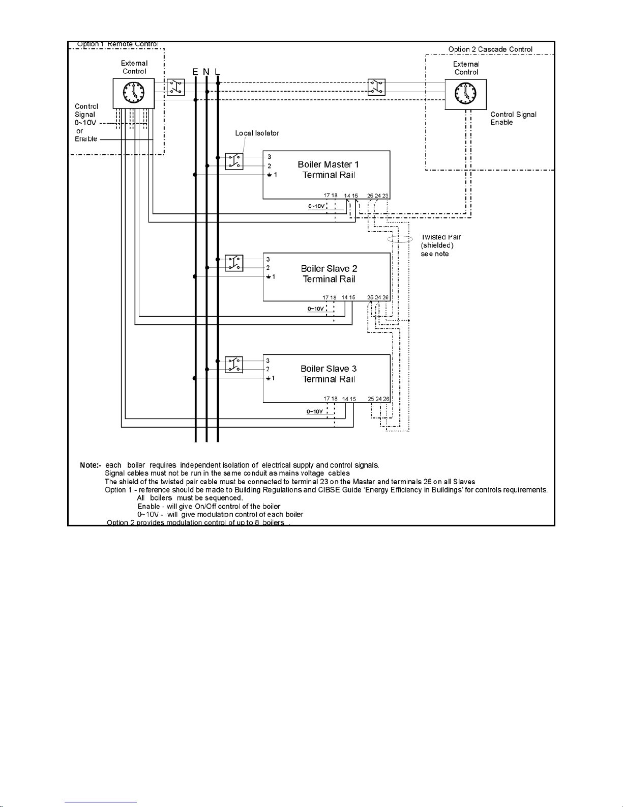
HAMWORTHY HEATING LTD
42
PUREWELL VariHeat he
500001155/F
Figure B1.2 - External Control Wiring for Multiple Boiler Installation
Page 48

HAMWORTHY HEATING LTD
43
PUREWELL VariHeat he
500001155/F
APPENDIX C - FLUE DATA
FLUE DATA
Model 65he 85he 105he
Nominal Flue Diameter - mm
100
Max back pressure allowable at flue outlet - mbar 0.9
Approx. Flue Gas Temperature 82/71°C - °C (Gross)
158 190 146
Approx. Flue Gas Volume @ 9.5 % CO2 - m3/h*
103.00 123.50 156.00
125he
175
188.00
1.5 1.9 2.5
Natural Gas
C1.0 FLUE SYSTEM
1. Detailed recommendations for flue systems are given in BS 6644, and IGE/UP/10. All flue discharges for plant
exceeding 135kW net input must comply with the third edition of the 1956 Clean Air Act Chimney Memorandum.
WARNING: THE FLUE DISCHARGE FROM A VARIHEAT BOILER MAY GENERATE A
PLUME ON START UP AT THE TERMINAL EXIT. THIS MUST BE CONSIDERED WITH
REGARD TO TERMINAL LOCATION AND ADJACENT BUILDING FABRIC.
C1.1 General Requirements
The Hamworthy Purewell Variheat he series of boilers are designed to be used with natural draught flues.
Flue systems should be designed in accordance with regulations and with reference to BS6644 and
IG/UP/10. These boilers are type B23 only (air intake from ventilated plant room and discharged via
vertical flue). See Fig C1.2.
The following points should be noted:
a. Due to the high thermal efficiency of the boiler condensation in the flue may occur. It is strongly recommended
that twin wall or insulated flue pipe is used on all external flue installations.
b. Care should be taken to ensure that the flue is installed such that any condensation is continuously drained. All
flues should have a maximum slope of 2° upwards in the direction of the exhaust gas flow (no horizontal
sections). All joints should be such that any condensation is directed back down the slope to an open drain
connection in the flue. The drain pipe must be manufactured from a corrosion resistant material and be at least
15mm diameter. It must also have a fall of at least 2-3° (approx. 30-50mm per meter) and connect to a drain via a
waste trap.
c. Boiler flue outlet sizes -
The connection to the boiler is suitable for 100mm flue duct, for connection to an open flue (chimney) system . The resistance
and maximum length of the flue system components is detailed in Figure C1.1.
A flue system designed with the same diameter as the boiler flue outlet may not provide satisfactory performance
in all applications. Conversely a flue system designed with a smaller diameter than the boiler flue outlet may
provide satisfactory performance. Consideration must be given to the correct calculation of the required flue size.
If in any doubt consult Hamworthy Heating Ltd who can supply a full flue design and installation service.
C1.2 Waste Gas Volume and Temperature.
Figure C1—Flue Data
* Note:- Flue gas volumes are corrected to a flue gas temperature of 15°C and barometric pressure of
1013.25mbar.
Page 49

HAMWORTHY HEATING LTD
44
PUREWELL VariHeat he
500001155/F
It is recommended that the volume and temperature of the waste gases used for design of the flue system are as
given in Table C1.
C1.3 Materials.
Materials used for the flue system must be mechanically robust, resistant to internal and external corrosion, noncombustible and durable under the conditions to which they are likely to be subjected. Consideration must be
given to avoid possible freezing of condense water traps and pipework
C1.4 Suction
The flue system must be designed acknowledging that there is a positive pressure generated by the boiler combustion
fan available to the flue system. It is recommended that a draught stabiliser is fitted to the flue system where the
draught is likely to become –ve at the boiler connection.
C1.5 Disconnection
Provisions should be made for disconnection of the flue pipe for servicing. It is advisable that bends are fitted with
removable covers for inspection and cleaning as appropriate.
WARNING: THE FLUE SYSTEM MUST BE SELF SUPPORTING AND NOT PRESENT
A RISK TO PEOPLE IN OR AROUND THE BUILDING.
C1.6 Flue Discharge
The flue system must ensure safe and efficient operation of the boiler to which it is attached, protect the
combustion process from wind effects and disperse the products of combustion to the external air. The flue must
terminate in a freely exposed position and be so situated as to prevent the products of combustion entering any
opening in a building. Where the flue diameter is less than 170mm (7”) diameter a terminal must be fitted. Where
the flue is of a larger size, consideration should be given to the fitting of a flue discharge terminal or grille to stop
ingress of birds etc.
C1.7 Surface Temperatures
Combustible materials in the vicinity of the boiler and flue shall not exceed 65°C during boiler operation. The flue
shall not be closer than 50mm to any combustible material, except where it passes through such material with a
non-combustible sleeve when the air gap may not be less than 25mm.
C1.8 Location
The flue system must not be placed or fitted where there is undue risk of accidental damage to the flue pipe or
undue danger to persons in the vicinity. Check that the flue and chimney are clear from any obstruction. Purewell
VariHeat he boilers are suitable for installation in a balanced compartment in accordance with the requirements of
BS 6644. Consult Hamworthy Heating Technical Department for help or assistance if in doubt.
C1.9. Condensate Discharge
Due to the high thermal efficiency of the boiler, a condensate trap is provided to connect the boiler sump to drain
so that any condensation that may occur within the boiler during start up conditions is removed. Consideration
should be given to possible freezing of condense water traps and pipework. This must be avoided at all times by
routing pipework within the building, where possible.
Page 50
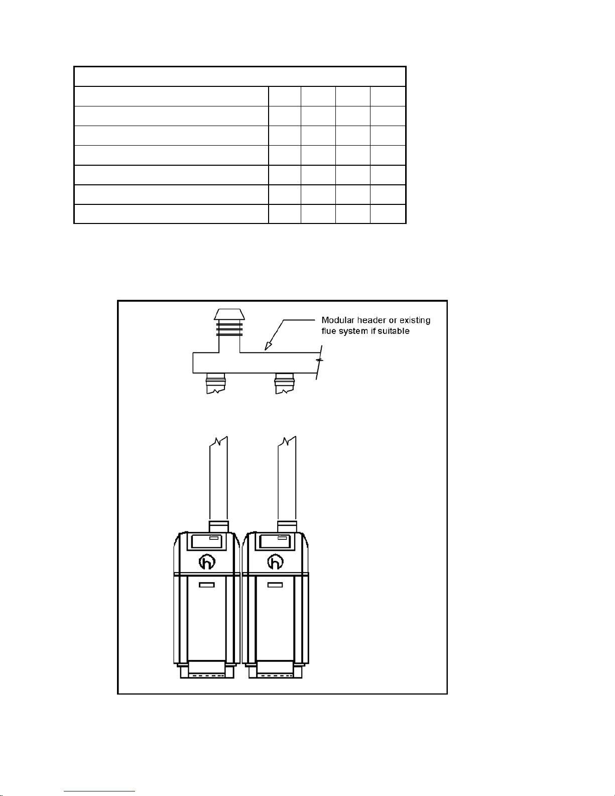
HAMWORTHY HEATING LTD
45
PUREWELL VariHeat he
500001155/F
Model
Component 65 he 85 he 105 he
Straight tube ø150mm maximum length (m) 149 88 69
45° bend ø150mm Equivalent tube length (m) 2 2 2
90° bend ø150mm Equivalent tube length (m) 2.2 2.2 2.3
125 he
47
2
2.3
Straight tube ø100mm maximum length (m) 19 12 8 5
45° bend ø100mm Equivalent tube length (m) 1.3 1.3 1.3 1.3
90° bend ø100mm Equivalent tube length (m) 1.5 1.5 1.5 1.5
Figure C1.2 - Open (Natural Draught) B23 Flue System
Figure C1.1 - Flue Resistance
Page 51

HAMWORTHY HEATING LTD
46
PUREWELL VariHeat he
500001155/F
APPENDIX D - VENTILATION
D1.1 Air Supply
Detailed recommendations for air supply are given in BS 6644 and BS 5440 Pt 2. The following notes are
intended to give general guidance. In all cases there must be provision for an adequate supply of air for both
combustion and general ventilation, in addition to that required for any other appliance.
Combustion air for the boiler is drawn through the rear of the boiler casing. The area must be kept open and free
from blockage at all times.
D1.2.1 Air Supply by Natural Ventilation - Open Flue applications
The boiler room must have, or be provided with, permanent air vents directly to the outside air, at high level and at
low level. For an exposed boiler house, air vents should be fitted, preferably on all four sides, but at the least on
two sides. Air vents should have negligible resistance and must not be sited in any position where they are likely
to be easily blocked or flooded or in any position adjacent to an extraction system which is carrying flammable
vapour. Grilles or louvres must be so designed that high velocity air streams do not occur within the space
housing the boiler.
Boiler house ventilation
Low level (inlet) - 4cm² per kW of total rated input (Net)
High level (output) - 2cm² per kW of total rated input (Net)
Compartment ventilation
Where the boiler is to be installed in a cupboard or compartment, permanent high and low level ventilation is
required which must communicate direct to outside, for cooling purposes.
Low level (inlet) - 10cm² per kW of total rated input (Net)
High level (output) - 5cm² per kW of total rated input (Net)
If the boilers are to operate during the summer months for 75% of the time a further 1 cm
2
or for 100% of the time
a further 2 cm
2
should be added per kW to both high & low openings.
D1.3 Air Supply by Mechanical Ventilation
Air supplied to the boiler room by Mechanical means should be as follows:
1) Mechanical ventilation must be interlocked with the boilers to prevent operation in
the event of ventilation fan failure
2) Mechanical inlet and mechanical extract can be utilised providing the design
extraction rate maintains the difference between inlet and extract flow rates shown in
figure D1.
3) Mechanical extract ventilation with natural inlet ventilation MUST NOT be used.
4) Additional rates may be required for summer operation.
D 1.4. Boiler House Temperatures
The air supplied for boiler house ventilation shall be such that the maximum temperatures within the boiler house
shall be as follows:
At floor level (or 100mm above floor level) = 25°C.
At mid-level (1.5m above floor level) = 32°C.
At ceiling level (or 100mm below ceiling level) = 40°C.
Page 52

HAMWORTHY HEATING LTD
47
PUREWELL VariHeat he
500001155/F
Figure D1 Mechanical Ventilation Flow Rates
Note * : Where the associated air extraction is also by means of a fan, this shall be selected such as not to
cause a negative pressure to develop in the boiler house and to maintain the difference between inlet and
extract flow rates shown above.
The calculated extract flow rate is the actual inlet flow rate minus the appropriate figure in the table above.
D 1.5. General Requirements
The air supply should be free from contamination such as building dust and insulation fibres from lagging. To
avoid unnecessary cleaning and servicing of the boiler modules, the boilers should not be fired whilst building
work is being undertaken.
High and low level ventilation grilles shall be positioned as high and as low as practicably possible. Low level
grilles should be located within 1 metre of the floor for Natural Gas and within 250mm of the floor for LPG. High
level grilles should be positioned within 15% of the boiler room height from the ceiling. High and low level grilles
shall communicate with the same room or space where compartment ventilation is used. Where grilles
communicate directly with outside air, they shall be positioned on the same wall.
Flow rate per kW total
rated heat input (net)
Inlet air
(Combustion
ventilation)
Difference between
inlet and extract air
(Inlet minus extract
ventilation)
m³/h m³/h
2.6 1.35 +/- 0.18
Boilers
Without
Draught
Diverters
Page 53

HAMWORTHY HEATING LTD
48
PUREWELL VariHeat he
500001155/F
APPENDIX E - WATER DATA
WATER DATA
Model 65he 85he 105he
Water Connections (Flow & Return) R2” male
Maximum Water Pressure - bar g 7
Water Content (not including headers) - litres
6 6 9
System Design Flow Rate @ 11°C ∆T Rise - litre/s
1.4 1.9 2.3
Minimum Flow Rate @ 15°C ∆T Rise - litre/s
1.0 1.4 1.7
Waterside Pressure Loss @ 11°C ∆T Rise - mbar
50 80 192
Waterside Pressure Loss @ 15°C ∆T Rise - mbar
28 47 98
125he
9
2.7
2.0
270
149
E1.1 Water Circulation System
The Purewell VariHeat he boiler has a low water content and the requirements of minimum water flow are given in
the above table. Recommendations for the water circulation system are given in BS 6644.
The following details are of particular importance for the correct installation of the water circulation system:
1) In a combined central heating and hot water system the hot water storage vessel must be of the
indirect cylinder or calorifier type. The hot water storage vessel should be insulated, preferably with
not less than 75mm (3”) thick mineral fibre, or its thermal equivalent.
2) Circulating pipework not forming part of the useful heating surface should be insulated to help prevent
heat loss and possible freezing, particularly where pipes are run through roof spaces and ventilated
cavities. Cisterns situated in areas which may be exposed to freezing conditions should also be
insulated. Furthermore, insulation exposed to the weather should be rendered waterproof.
3) Drain valves must be located in accessible positions which permit the draining of the whole system,
including the boiler and hot water storage vessel.
4) Each boiler module has R2” male flow (indicated with a red spot) and return (indicated with a blue
spot) connections. Boilers should be connected by flow and return headers. Headers should be
connected to the system in a ‘reverse / return’ arrangement (the water flow in each header is in the
same direction) to ensure equal flow in each module, or with a ‘single pipe header system’. Figure
E1.2 on the following page show typical layouts.
5) Ideally, individual valves should be fitted to each module to enable isolation from the system,
however, the arrangement must comply with the requirements of BS 6644.
E1.2 Minimum System Water Pressure
To comply with guidance note PM5 (Health and Safety Executive), the minimum pressure requirements at the boiler are
given below as examples:-
1) Single installed boiler running at 82°C flow temperature. Minimum head required is not less than 2.0 metres or 0.2 bar.
2) Single installed boiler running at 90°C flow temperature. Minimum head required = 3.0 metres or 0.30 bar.
3) Modular boiler installation running at 82°C flow temperature and 11°C rise across system. Minimum head required =
4.4 metres or 0.43 bar.
4) Modular boiler installation running at 82°C flow temperature and 15°C rise across system. Minimum head required =
6.5 metres or 0.64 bar.
E1.3 Pressure Relief Valve (Safety Valve)
The most important single safety device fitted to a boiler is its safety valve. Each boiler module is provided with a
capped R¾” stub pipe for the fitting of a safety valve (not supplied). BS 6644 provides comprehensive information
for the selection and location of safety valves and attention is drawn to the higher capacity requirements of safety
valves for pressurised hot water systems.
Boiler Output Feed mm Vent mm
60 - 150kW 25 32
150 - 300 kW 32 38
300 - 600 kW 38 50
Figure E1.1 Cold Feed and Vent Pipe Sizes
Figure E1 - Water Data
Page 54
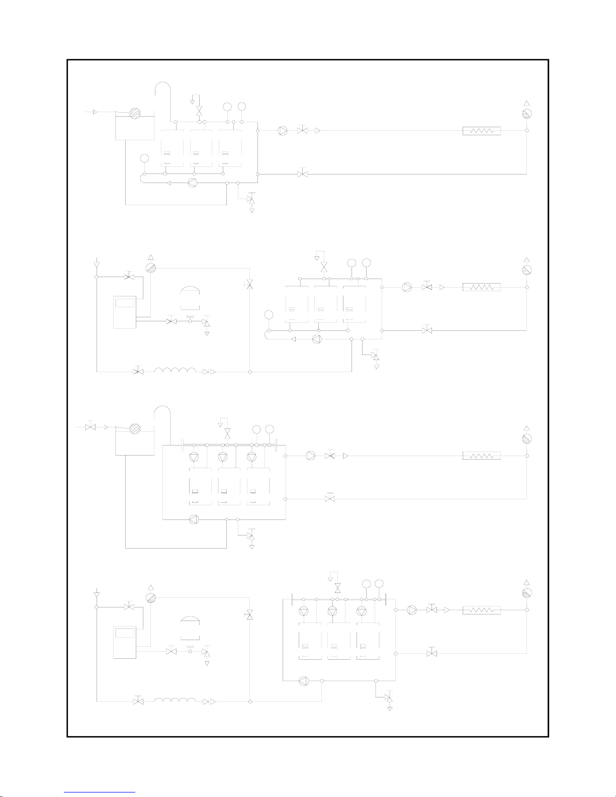
HAMWORTHY HEATING LTD
49
PUREWELL VariHeat he
500001155/F
Figure E1.2 - Typical Piping Layouts
UNVENTED SYSTEM: Primary loop, Hamworthy recommended system .
VENTED SYSTEM: Single pipe header
Mains water
Feed
pip e
expansion
Feed &
tank
valve
Float
Valve
Saf ety
va lve
Dr ain
Expansion pipe
Pres sure &
P
gauges
Temperature
T
Modu le
Hamworthy M odular Boilers
1
Module
2
Module
3
VENTED SYSTEM: Primary loop, Hamworthy recommended system.
Circulation pump
va lve
Drain
Expansion pipe
Feed
pip e
Mains wat er
Hamworthy Modul ar Boile rs
Module
Saf ety
T
Feed &
expansion
tank
va lve
Module
1
2
valve
Float
Drain
Valve
Module
3
P
gauges
Pres sure &
Temperature
T
Circulation pump
Valve
(System)
Heating load
Automatic
Ai r Vent
Valv e
Air Vent
Aut omatic
Va lv e
va lve
Drain
Va lv e
Module
Hamwo rthy Modular Boilers
Saf ety
T
valve
Module
1
2
Drain
3
Module
P
gauges
Pressur e &
Temperature
T
Automatic
Ai r Vent
Heating load
Locksh ield
valv e
fill line
Temporary Double
ch e c k
va l v e
vessel
Expansion
valve
Lockshield
Mains water
va lve
Drain
va lve
Lockshield
(Primary loop )
(Sys tem)
Circulation pump
Valve
Circulation p ump
Valve
(System)
Automatic
Heating load
Ai r Vent
Circulation pump
Hamworthy Modular Boiler s
Module
Drain
UNVENTED SYSTEM: Single pipe header
1
Circulation pump
Module2Module
3
Temper ature
gauges
Pres sure &
Saf e ty
va lv e
P
T
Heating load
Automatic
Ai r Vent
Valve
(System)
Valve
(Primary loop)
(Primary loop)
Circulation pump
Locksh ield
valv e
Mains water
Lockshield
valve
Drain
va lve
vessel
Temporary
fill line
va lve
Lockshield
Dou b le
va l v e
ch e c k
Expansion
Air Vent
Aut omatic
Valv e
(Primary loop)
Circulation pump
Drain
valve
va lve
Drain
Page 55

HAMWORTHY HEATING LTD
50
PUREWELL VariHeat he
500001155/F
E1.4 Open Vent and Cold Feed Pipe.
Every boiler or group of boilers should have an open vent pipe and cold feed pipe installed between the boiler and
the first water isolating valve. The minimum bore (mm) of these pipes per installation is shown in the table. The
vent pipe must rise continually, any valve fitted between a boiler and the open vent pipe for maintenance
purposes shall be of the 3 way type such that when closed to the vent pipe the boiler will be open to atmosphere.
The vent pipe shall be protected against freezing where this might occur. See BS 6644 for detailed information on
Open Vent and Cold Feed Pipes.
E1.5 Altitude Gauge (Water Pressure Gauge)
Every boiler or group of boilers should be provided with an altitude gauge complete with isolating valve. See
Figure E1.2 for typical position.
E1.6 Thermometer
A thermometer complete with pocket should be fitted in the pipework to indicate water flow temperature. See
Figure E1.2 for typical position.
E1.7 Drain Valves
Each boiler is fitted with a 15mm NB drain valve in the boiler return to drain the boiler only. The heating system in
total should have drain valves as recommended by BS 6644. See Figure E1.2 for typical position.
E1.8 Circulating Pump
One or more circulating pumps will be required to circulate water around the boilers and heating system. The
pump should be sited to facilitate servicing. It is important that when Purewell VariHeat he boilers are used to
replace boilers on an existing system, the pumps should be checked for performance against the new boiler
waterside pressure loss to ensure that the minimum flow rate can be obtained. It is also important that the existing
system be flushed through twice to remove any loose matter which may have accumulated. If in any doubt
regarding the cleanliness of the system, a coarse filter should be fitted in the return pipework to the boilers.
If boiler / system pump(s) are not controlled by the boiler, a pump overrun (not Hamworthy Heating Ltd supply)
should be fitted which must run for a minimum of 5 minutes on shutdown of the last boiler.
E1.9 Minimum Water Flow Rates
Minimum water flow rates are shown in table at beginning of Appendix E. These flow rates should be maintained
through the boiler at all times whilst the boiler is firing. If the water flow rate is allowed to fall below the minimum
the boiler heat exchanger could fail due to the resultant scale formation. Particular attention should be paid to the
restriction of external flow circuits during periods of low heat demand.
E1.10 Waterside Pressure Drop
The waterside hydraulic resistance (Pressure drop) is given in table E1 at beginning of Appendix E.
E1.11 Water Flow Controls
Any external mixing valve / shunt pump or similar controls MUST always ensure that the minimum water flow rate
as given in table at beginning of Appendix E is maintained. If there is any doubt relating to site flow conditions it is
suggested that a flow switch is fitted. The flow switch should be connected such that the boiler will shut down if
insufficient flow occurs.
E1.12 Frost Protection
Consideration should be given to fitting a frost thermostat set at approximately 4°C
E1.13 Unvented Systems
Refer to Figure E1.2 for typical layout of an unvented (Pressurised) Hot Water System. For system design refer
to BS 7074 Part 2. In order to correctly size a pressurisation unit for any heating system the following parameters
Page 56
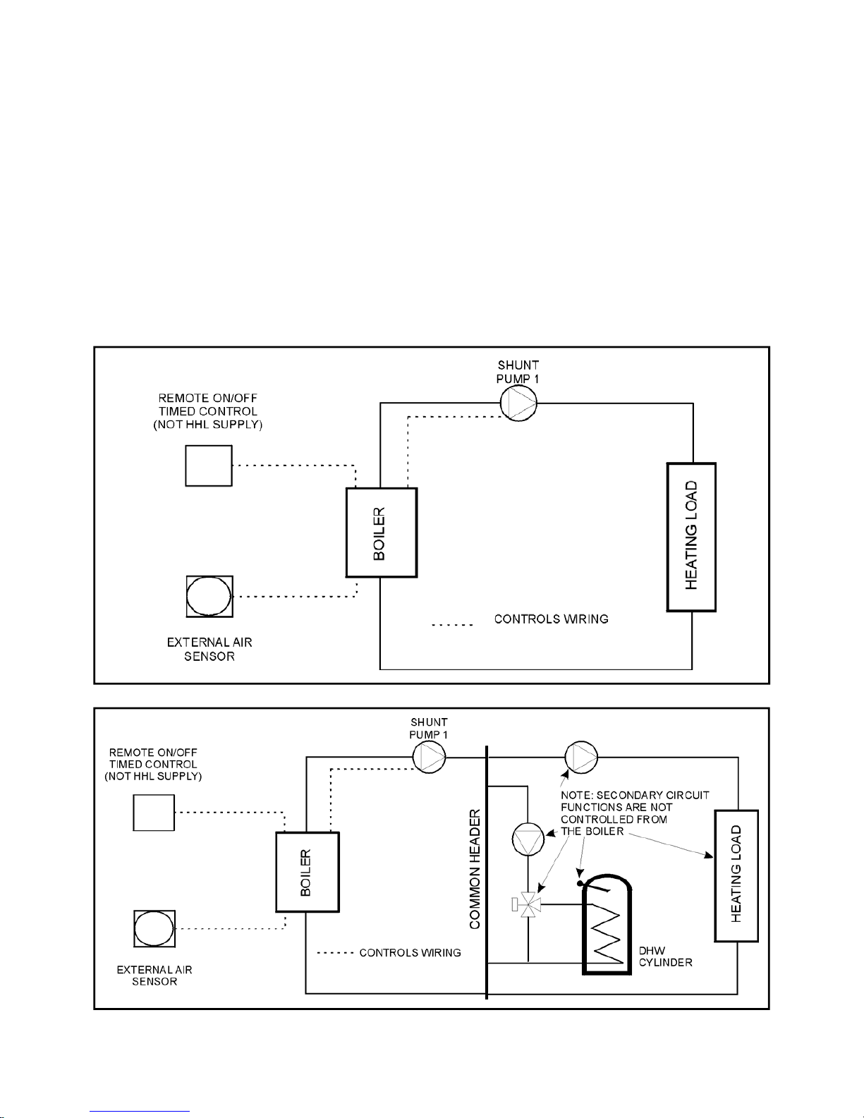
HAMWORTHY HEATING LTD
51
PUREWELL VariHeat he
500001155/F
are required.
1) Static height of highest component in system (metres)
2) System volume. If this is not known, a general rule of thumb of 10litres/kW of installed boiler power
can be used.
3) Maximum flow temperature (°C)
4) Maximum system hot working pressure, generally given in bar gauge.
From the parameters given, Hamworthy Heating can size the pressurisation unit and also the expansion vessel
required.
Care must be taken in sizing expansion vessels to ensure maximum acceptance factors are not exceeded.
Normally manufacturers of vessels impose a limit of 0.5. This value must not be exceeded at any time during the
operation of the boiler, this includes the over pressure condition should a safety valve lift.
Consideration should also be given to sizing of the safety valve(s) in the system. Refer to BS 6644 for further
information and to BS 6880: Part 1 for design considerations.
Figure E 1.3.1 - Schematic for Single Boiler System
Figure E 1.3.2 - Schematic for Single Boiler, Primary Circuit System
Page 57
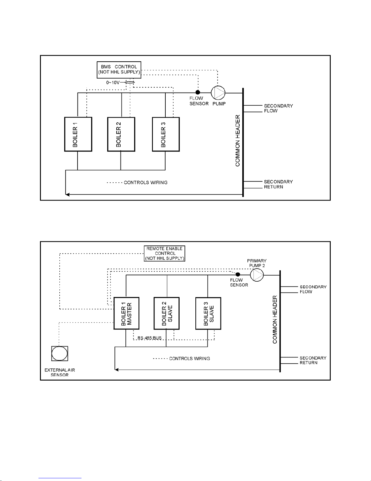
HAMWORTHY HEATING LTD
52
PUREWELL VariHeat he
500001155/F
Figure E 1.3.4 - Schematic for Multiple Boiler (Internal Cascade), Primary Circuit System
Figure E 1.3.3 - Schematic for Multiple Boiler (External 0~10V), Primary Circuit System
Page 58

HAMWORTHY HEATING LTD
53
PUREWELL VariHeat he
500001155/F
NOTES
Page 59

HAMWORTHY HEATING LTD
54
PUREWELL VariHeat he
500001155/F
USEFUL USER INFORMATION
NOTES
INSTALLER SITE ADDRESS
BOILER TYPE BOILER SIZE(S) UNIT NO(S). SERIAL NO(S). FLUE
Page 60

Technical Enquiries
To supplement the detailed technical brochures, technical advice on the application and use of products in the Hamworthy
Heating range is available from our technical team in Poole and our accredited agents.
Site Assembly
Hamworthy offer a service of site assembly for many of our products in instances where plant room area is restricted. Using our
trained staff we offer a higher quality of build and assurance of a boiler built and tested by the manufacturer.
Commissioning
Commissioning of equipment by our own engineers, accredited agents or specialist sub – contractors will ensure the equipment
is operating safely and efficiently.
Maintenance Agreements
Regular routine servicing of equipment by Hamworthy service engineers inspects the safety and integrity of the plant, reducing
the risk of failure and improving performance and efficiency. Maintenance agreements enable our customers to plan and
budget more efficiently.
Breakdown service, repair, replacement
Hamworthy provide a rapid response breakdown, repair or replacement service through head office at Poole and accredited
agents throughout the UK.
Spare Parts
A comprehensive spare parts service is operated from our factory in Poole, providing replacement parts for both current and
discontinued products. Delivery of parts and components is normally from stock within seven days. However, a next day delivery
service is available for breakdowns and emergencies.
Customer After Sales Services
Page 61

Notes
Page 62

Hamworthy reserves the right to make changes and improvements which may necessitate alteration to the specification without prior notice.
Hamworthy Heating Accredited Agents
North West England
Gillies Modular Services
210-218 New Chester Road, Birkenhead, Merseyside L41 9BG
tel: 0151 666 1030 fax: 0151 647 8101
Southern Ireland
HEVAC Limited
Naas Road, Dublin 12, Ireland
tel: 00 353 141 91919 fax: 00 353 145 84806
Northern Ireland
HVAC Supplies Limited
Unit A6, Dargan Court, Dargan Crescent, Belfast BT3 9JP
tel: 02890 777737 fax: 02890 771233
Scotland
McDowall Modular Services
14-46 Lomond Street, Glasgow, Scotland G22 6JD
tel: 0141 336 8795 fax: 0141 336 8954
North East England
Allison Heating Products
12 Sunnyside Lane, Cleadon Village, Sunderland SR6 7XB
tel: 0191 536 8833 fax: 0191 536 9933
Customer Service Centre
Hamworthy Heating Limited,
Fleets Corner, Poole,
Dorset BH17 0HH.
Telephone: 0845 450 2866
Fax: 01202 662522
Email: [email protected]
Website: www.hamworthy-heating.com
 Loading...