

Page 1
Installation, Commissioning
and Servicing Instructions
Atmospheric Cast Iron Boiler
40kW to 120kW Output
PERMANENT IGNITION CONTROLS
Classic and Integra Models
Purewell
Gas Fired
Modular Boiler System
IMPORTANT NOTE
THESE INSTRUCTIONS MUST BE READ AND UNDERSTOOD BEFORE
INSTALLING, COMMISSIONING, OPERATING OR SERVICING EQUIPMENT.
BS EN ISO 9001:1994
Certificate No. FM 10082
NATURAL GAS I
LPG-PROPANE I
2H
3P
Page 2

Customer Services
TECHNICAL ENQUIRIES 01202 662527 / 662528
To supplement the detailed technical brochures, technical advice on the application and use of products in
the Hamworthy Heating range is available from our technical team in Poole and our accredited agents.
SITE ASSEMBLY 01202 662555
Specialist teams are available for on site assembly of the full range of Hamworthy boilers (excluding
Lulworth). Boiler sections for site assembly must be positioned within the boiler house prior to the arrival
of the assembly team and provide sufficient space for safe working. Handling sections into boiler houses
other than at ground level may be subject to additional charges.
The normal assembly price does not include for the fitting of boiler casings or the burner, however this can
be carried out at the time of build at additional cost.
Providing the facilities are available on site, a hydraulic test will be carried out within the terms of BS779.
Upon completion a certificate of assembly and test will be issued.
COMMISSIONING 01202 662555
Commissioning of equipment by Hamworthy Heating's own engineers, accredited agents or specialist subcontractors will ensure that the equipment is operating safely and efficiently. Hamworthy commissioning
reports provide a detailed record of the original status of the plant, which is essential for future routine
maintenance and trouble free operation.
Standard warranty terms provide for the free of charge replacement of defective parts, but does not
include labour. When the equipment is commissioned and routinely maintained by Hamworthy Heating
under a Service Maintenance Agreement then the warranty terms will cover both parts and labour.
MAINTENANCE AGREEMENTS 01202 662555
Regular routine servicing by Hamworthy Heating's engineers ensures trouble free operation and optimum
efficiency. The frequency of visits required is variable, dependent upon the equipment type and usage.
Annual service agreements are available on all Hamworthy products to meet individual requirements.
Planned maintenance of equipment by routine servicing reduces operational costs considerably below that
associated with repair or breakdown approach.
BREAKDOWN SERVICE, REPAIR, REPLACEMENT 01202 662555
Even when the commissioning and routine servicing has been carried out to the highest standard there
are always occasions when the unexpected breakdowns occur. Hamworthy provide a rapid response
breakdown, repair or replacement service through head office at Poole and accredited agents located
throughout the UK.
SPARE PARTS 01202 662525
A comprehensive spare parts service is operated from our factory in Poole, providing replacement parts
for both current and discontinued products. In some instances spares may be available from accredited
agents.
Delivery of parts and components is normally from stock within 7 days. However, a 24 hour delivery
service is available for breakdowns and emergencies for the additional cost of the courier. Please contact
our spares team, providing details of product type, serial number, model or any other identifying marks or
codes to determine part requirements wherever possible.
Page 3

PUREWELL ATMOSPHERIC HOT WATER BOILER FOR HEATING
AND DOMESTIC HOT WATER INSTALLATIONS
INSTALLATION, COMMISSIONING AND SERVICING INSTRUCTIONS
PERMANENT IGNITION CONTROLS (ECO CONTROL)
CLASSIC MODELS WITH DRAUGHT DIVERTER
Or
PRIMARY FLUE DAMPER
40,50,60,70,80,95,105 & 120 kW
and
INTEGRA MODELS
40,70 & 100 kW
NOTE: THESE INSTRUCTIONS SHOULD BE READ AND UNDERSTOOD BEFORE
ATTEMPTING TO INSTALL, COMMISSION OR OPERATE THIS UNIT
THE PUREWELL BOILER IS INTENDED FOR USE AS A COMMERCIAL APPLIANCE
AND IS NOT CERTIFIED FOR USE IN DOMESTIC APPLICATIONS OR HABITABLE
AREAS.
THIS BOILER IS FOR USE ON GROUP H NATURAL GAS (2ND FAMILY)I
PROPANE (3
RD
FAMILY)I3P. PLEASE ENSURE RELEVANT INFORMATION REQUIRED
2H OR LPG-
WITHIN DOCUMENT IS FOUND RELATING TO SPECIFIC GAS TO BE FIRED BEFORE
FIRING BOILER.
THIS BOILER COMPLIES WITH ALL RELEVANT EUROPEAN DIRECTIVES.
EC TYPE CERTIFICATE No. BG/EC-93/20
PRODUCT IDENTIFICATION No.87AO20
PUBLICATION NO. 500001090
ISSUE ‘B’
NOVEMBER 2001
HAMWORTHY HEATING LTD. PUREWELL PERMANENT IGNITION 500001090/B
i
Page 4

HAMWORTHY HEATING LTD. PUREWELL PERMANENT IGNITION 500001090/B
ii
Page 5

CONTENTS
INDEX ................................................................................ iii
1.0 INTRODUCTION ..............................................................................…... 1
2.0 TECHNICAL DATA ..........................................................................…… 1
3.0 GENERAL REQUIREMENTS ..........................................................…… 2
3.1 Related Documents
3.2 Feed Water Quality
3.3 Adequate Water Flow
3.4 Time Clock Control
3.5 Minimum System Water Pressure
4.0 LOCATION .......................................................................................…… 4
5.0 GAS SUPPLY...................................................................................……. 4
5.1 Service Pipes
5.2 Meters
5.3 Gas Supply Pipes
5.4 Boosted Supplies
5.5 Boiler House Control Valve
5.6 Boiler Gas System Leak Check
PAGE
6.0 FLUE SYSTEM ................................................................................…… 5
6.1 General Requirements
6.2 Design Waste Gas Volume and Temperature
6.3 Flue Condensation
6.4 Materials
6.5 Disconnection
6.6 Flue Discharge
6.7 Surface Temperatures
6.8 Flue System Location
7.0 AIR SUPPLY ....................................................................................…… 6
7.1 Air Supply by Natural Ventilation
7.2 Air Supply by Mechanical Ventilation
8.0 WATER CIRCULATION SYSTEM ...................................................…… 6
8.1 General
8.2 Pressure Relief Valve (Safety Valve)
8.3 Open Vent Pipe and Cold Feed Pipe
8.4 Altitude Gauge (Water Pressure Gauge)
8.5 Thermometer
8.6 Drain Valves
8.7 Circulating Pump
8.8 Minimum Water Flow Rates
8.9 Waterside Pressure Drop
8.10 Control Schemes
8.11 Unvented Pressurised Systems
8.12 Modular Boiler Control Schemes
HAMWORTHY HEATING LTD. PUREWELL PERMANENT IGNITION 500001090/B
iii
Page 6

PAGE
9.0 ELECTRICAL SUPPLY ...................................................................... 8
9.1 Site Wiring
10.0 BOILER ASSEMBLY AND INSTALLATION..................................... 9
10.1 General
10.2 Heat Exchanger Insulation Fitting Instructions
10.3 Gas Pipe Fitting Instructions
10.4 Connection to the Flue System
10.5 Gas Connection
10.6 Water Connections
10.7 Casing and Controls Assembly
11.0 COMMISSIONING AND TESTING ...............................................….. 13
11.1 Electrical Installation
11.2 Gas Installation
11.3 Water Circulation System
11.4 Commissioning the Boiler
11.5 Boiler Checks Prior to Lighting
11.6 Gas Pressure Adjustment and Combustion Checks
11.7 Temperature Limiter (Limit Thermostat)
11.8 User’s Instructions
12.0 FAULT FINDING............................................................................…. 15
12.1 Safety Features Summary
12.2 Fault Finding Procedures
12.3 Possible Causes of Boiler Lockout
13.0 SERVICING.....................................................................................…….. 16
14.0 REPLACEMENT OF FAILED COMPONENTS...............................……… 17
15.0 RECOMMENDED SPARES............................................................………. 19
APPENDIX ‘A’ - INFORMATION RELATING TO PROPANE FIRING.....…….. 30
FIGURES PAGE
Figure No. 1 Performance and General Data................................................ 2
Figure No. 2 Flow Rates/Pressure Drop Table…………................................ 3
Figure No. 3 Gas Valve Leak Check Procedure............................................ 5
Figure No. 4 Mechanical Ventilation Flow Rates.............................................. 6
Figure No. 5 Heat Exchanger Insulation Fitting Instructions............................. 9/10
Figure No. 6 Gas Pipe Fitting Instructions……................................................ 10
Figure No. 7 Casing Assembly Details....................................................... 12/13
Figure No. 8 Boiler Installation Typical Layout (Vented and Un-vented)…… 20
Figure No. 9 Overall Dimensions of Boiler and Recommended Clearances . 21
Figure No. 10 Front Assembly Showing General Layout.................................... 22
Figure No. 11 Gas Flow in Pipes.......................................………………….... 23
Figure No. 12 Typical Boiler Wiring Diagram (inc. Options)............................ 24
Figure No. 13 Diagram of Igniter Assembly.................................................... 25
Figure No. 14 Diagram of Various gas valves fitted...................................... 26
Figure No. 15 General Fault Finding.............................................................. 27/28
Figure No. 16 Damper Actuator Motor ……………………………………………. 29
HAMWORTHY HEATING LTD. PUREWELL PERMANENT IGNITION 500001090/B
iv
Page 7

1.0 INTRODUCTION
1.1 A competent person holding ‘CORGI’ registration
or equivalent must install this boiler. All installations
MUST conform to the relevant Gas Safety and
Building Regulations. Health & Safety requirements
must also be taken into account when installing any
equipment. Failure to comply with the above may lead
to Prosecution.
1.2 These instructions are for Group H Natural Gas
(2nd Family) and LPG-Propane (3rd Family). The
information relative to propane firing is to be found in
Appendix ‘A’. Boilers MUST NOT use gas other than
that for which they were designed and made for.
1.3 The Purewell is an Atmospheric, Gas Fired boiler
manufactured from horizontal cast iron sections,
nippled at alternate ends. These sections are
mounted on a fabricated mild steel basket assembly,
which houses the burner bar and igniter assemblies.
A unique radiant baffle is fitted beneath the burner
bars, protecting the floor below by reducing heat lost
from the boiler.
The ‘Classic’ version of the Purewell boiler is
designed to be connected to the flue via a specifically
designed draught diverter. The draught diverter
MUST be fitted into the spigot on top of the heat
exchanger as supplied. NO modification or variance is
permitted as this may change operational
characteristics.
An optional On/Off Primary Flue Damper kit is
available for ‘Classic’ models only. This damper
MUST be fitted into the spigot on top of the heat
exchanger as supplied. NO modification or variance is
permitted as this may change operational
characteristics. Flue outlets from more than one boiler
may be connected together to form a header.
Technical Department for help or assistance if in
doubt.
1.6 The Purewell boiler is not suitable for direct
connection to domestic hot water supplies or gravity
fed heating systems.
1.7 The Purewell boiler can be installed with either
reverse return water flow layout or with single pipe
header layout. See Figure No. 8 for typical schematic
layout.
Hamworthy Heating can supply a pre-designed
arrangement of components, which will produce a
"reverse-return" assembly. Please contact
Hamworthy Heating for information.
1.8 It is good practice in all heating installations to use
some form of water treatment to reduce formation of
lime scale and black iron oxide sludge. The high
efficiencies produced by the Purewell Boiler can easily
be reduced by lime scale formation. If a Pressurised
unit is used, it is prudent to include an hours run meter
to give an indication of pump running time and hence
raw water make up. Any leaks should be attended to
as soon as possible to avoid calcium salt build up
within the boiler's waterways.
2.0 TECHNICAL DATA
2.1 Overall dimensions are shown in Figure No. 9.
Both single and multi boiler arrangements are shown.
The Purewell boiler can be installed as a single unit or
in modular form where a 'multi' casing reduces
required floor area. Each boiler has an independent
door for access to the controls and other working
components.
‘Integra’ versions have an in-built draught diverter and
can therefore be connected direct to a header
assembly via a suitable flue pipe.
1.4 The Purewell boiler is available with an optional
Flame Failure kit, allowing a signal to be generated
should the pilot drop out. NOTE! There is no facility to
electrically interface any input/output with the boiler
controls. Refer to Section 9.0 ELECTRICAL SUPPLY
for details.
1.5 If the boiler is to be connected to an un-vented
(pressurised) heating system, care must be taken to
ensure all extra safety requirements are met and that
the relevant interlocks will shut down the boiler(s)
should a high or low pressure fault occur.
The Pressurisation unit must also incorporate a low
level water switch, which protects the water pumps,
and will directly or indirectly shut down the boiler plant
should a low water condition occur.
Consideration should also be given to the maximum
working pressure of the boiler as given in Section
2:TECHNICAL DATA. Consult Hamworthy Heating
It is recommended that a maximum of 6 boilers can be
positioned on 533mm (21") centres if required. Larger
numbers should be split into two or more banks with
150mm (6") between each bank. NOTE! When
installing modular units on 533mm (21") centres, the
casing support rail or spacing plates should be fitted
between each boiler before bolting together. See
Section 10.1:General Installation of Boilers Ref.: spacing plates for further information.
2.2 General Information and Technical Data relating to
Natural Gas is shown in Figure No. 1. Technical data
relating to propane firing can be found in Appendix ‘A’.
2.3 Screw threads: All screw threads used in the
Purewell boiler conform to the following: -
ISO 7/1 or ISO 228/1 for pipe threads where
applicable.
ISO 262 for all general screw threads.
HAMWORTHY HEATING LTD. PUREWELL PERMANENT IGNITION 500001090/B
1
Page 8

Figure No. 1 - Performance and General Data information.
GENERAL DATA 40 50 60 70 80 95 100 105 120
Boiler input kW (Gross) 49.3 63.4 74.5 88.4 101 120 126 132 150
Boiler input kW (Nett) 44.4 57.1 67.1 79.6 90.9 108.5 113.6 118.8 135
Boiler output kW 40 50 60 70 80 95 100 105 120
Gas flow rate m³/h 4.73 5.92 7.1 8.27 9.44 11.19 11.8 12.36 14.1
Gas manifold press
13.4 12.5 11.9 11.0 9.5 11.5 10.2 11.2 11.0
mbar
FLUE DATA
Nominal flue Dia.
206 206 206 206 206 256 - 256 256
Classic
Nominal flue Dia. Integra
Approx. flue gas tempqC
Approx. flue gas vol. @
9% CO
& 100qC m³/h *
2
206 - - 206 - - 256 - -
190 200 190 220 230 200 205 215 205
73.8 92.4 110.8 129.1 147.3 174.6 184.1 192.9 220
GAS DATA
Nominal gas inlet press ------------------------------------------- 20 mbar --------------------------------
Maximum gas inlet
------------------------------------------- 25 mbar -------------------------------press.
Injector Dia. mm 2.7 3.1 3.4 3.75 4.2 3.9 4.1 4.1 4.4
Pilot burner Q349A-1034 (with 56-42A injector)
No. of Burner
------------------------------- 4 ------- -------------- 5 ------------bars/Injectors
Gas inlet connection. ----------------------------- R¾ ----- ------------ R1 -----------
WATER DATA
Water connections Flow Rc2 Return Rc2
Loss mbar @ 15°C 'T
2.75 4.31 8.63 11.57 14.9 22.55 25 27.45 47.06
Maximum water press. --------------------------------------------- 6 bar g -------------------------------
Water content litres 30 30 37.1 37.1 37.1 44.2 44.2 44.2 51.3
Litres/sec @ 11°C 'T
Litres/sec @ 15°C 'T
Litres/sec @ 22°C 'T
0.87 1.08 1.30 1.52 1.74 2.06 2.17 2.28 2.6
0.64 0.80 0.95 1.12 1.27 1.51 1.59 1.67 1.91
0.43 0.54 0.65 0.76 0.87 1.03 1.08 1.14 1.3
ELECTRICAL DATA
Normal Supply Voltage ------------------------------------- 230 V AC 50 Hz 1 ph -----------------------
------------------------------------------ fused @ 2A -----------------------------Power Consumption ------------------------------------- ---------- 35W ----------------------------------
* NOTE! Flue gas volumes are based on a gross flue gas temperature of 100qC at 1013mbar. This is
considered to be the predicted temperature of the products in the secondary flue downstream of the draught
diverter.
3.0 GENERAL REQUIREMENTS
The installation of the boiler MUST be in accordance
3.1 Related Documents.
with the relevant requirements of the Gas Safety
Regulations, Building Regulations, IEE Regulations
Gas Safety Installations and Use Regulations
and the byelaws of the local water undertaking.
1998, (As amended). It is Law that competent
persons in accordance with the above regulations
install all gas appliances. Failure to install
appliances correctly could lead to prosecution. It is
in your own interest, and that of safety, to ensure
The installation should also be in accordance with
any relevant requirements of the local gas region
and local authority and the relevant
recommendations of the following documents: that this law is complied with.
HAMWORTHY HEATING LTD. PUREWELL PERMANENT IGNITION 500001090/B
2
Page 9

British Standards
BS 7074: Application, selection and installation of
expansion vessels and ancillary equipment for
sealed water systems. Part 2: Code of practice for
low and medium temperature hot water systems.
information, but the following extracts from the above
references are emphasized since failure to comply
with these requirements will almost certainly result in
an unsatisfactory installation.
3.2 Feed Water Quality
BS 6891: Installation of low-pressure gas pipework
of up to 28mm in domestic premises. (For larger
installations see IGE/UP/1, IGE/UP/1A and
IGE/UP/10)
BS 6644: Installation of Gas Fired Hot Water Boilers
- 60kW to 2MW.
BS 6700: Design, installation, testing and
maintenance of services supplying water for
domestic use.
BS 6880: Part 1, 2 & 3: Code of practice for low
temperature hot water heating systems of output
greater than 45kW.
BS EN 60335, Part 1. Safety of Household & similar
electrical appliances. BS 3456, Part 201: Electrical
Standards.
CP 342: Centralised hot water supply.
Part 2: Buildings other than individual dwellings.
I. Gas E. Publications
IGE/UP/1 Soundness testing and purging of
industrial and commercial gas installations.
IGE/UP/1A Soundness testing and direct purging of
small low pressure industrial and commercial natural
gas installations.
IGE/UP/2 Gas installation pipework, boosters and
compressors in industrial and commercial premises.
IGE/UP/10 Installation of gas appliances in industrial
and commercial premises Pt.1 flued appliances.
Health and Safety Executive: Guidance note PM5 - Automatically controlled
steam and hot water boilers.
CIBSE Publications: -"CIBSE Guide" It is
impractical in this document to specify all relevant
If the boiler feed water has a high degree of
hardness, it is recommended that the water be
treated to prevent precipitation of scale or sludge in
the boiler water passageways. Details of additives
can be obtained from any reliable manufacturer of
water treatment products or the local water authority.
It should be noted however, that even if the boiler
water is of average hardness, not requiring
treatment, subsequent draining of the system for
repair or constant make-up water due to an
undetected leak would cause additional deposits and
gradual build-up of scale. It is essential therefore,
that leaks are attended to promptly and draining is
kept to an absolute minimum.
It is recommended that the system be flushed out at
least twice with hot water before any water treatment
is added. If any doubt exists regarding the internal
cleanliness of an old system, consideration should
be given to the fitting of a coarse filter in the return
pipework to the boilers.
3.3 Adequate Water Flow
The Hamworthy Purewell boiler is designed as a
quick response, low water content unit, able to run
continuously with maximum reliability. Care should
be taken in the initial design and layout having due
regard for adequate water flow through the boilers
and the influence of the system controls. NOTE!
The Standards Authority recommend a minimum
return temperature of 50°C in all heating systems
other than condensing boilers.
Figure No. 2 shows recommended and minimum
water flows required. The control system and
valves, where fitted, should be regulated to avoid
lower flows occurring.
The flow corresponding to 22°C temperature rise
across the boiler is the minimum recommended flow
at any time. For boiler pressure drop see Figure No.
2.
Figure No. 2 - Flow-rate Pressure Drop Table.
Model 405060708095100105120
Flow @ 11°C 'T rise
0.87 1.08 1.30 1.52 1.74 2.06 2.17 2.28 2.6
litres/second
Resistance mbar 5.1 7.84 15.69 20.59 26.47 37.25 41.12 50 84.31
Flow @ 15°C 'T rise
0.64 0.80 0.95 1.12 1.27 1.51 1.59 1.67 1.91
litres/second
Resistance mbar 2.75 4.31 8.63 11.57 14.9 22.55 25 27.45 47.06
Flow @ 22°C 'T rise
0.43 0.54 0.65 0.76 0.87 1.03 1.08 1.14 1.3
litres/second
Resistance mbar 1.27 2.06 4.12 5.49 7.06 11.76 12.94 13.23 22.55
HAMWORTHY HEATING LTD. PUREWELL PERMANENT IGNITION 500001090/B
3
Page 10

3.4 Time Clock Control
5.0 GAS SUPPLY
In order to avoid local overheating and progressive
calcium deposition at zero flow conditions where
boilers are operated from time clocks, provision
should be made for a 5 minute circulating pump
over-run after the last boiler has ceased firing.
NOTE! As the boiler electrical connection is via a 3
pin IEC fused plug and socket, any time clock, or
external means of control, must interrupt the live
supply to the boiler. - see Section 9.0:
ELECTRICAL SUPPLY for details. See Figure No.
12 for wiring details.
3.5 Minimum System Water Pressure
To comply with guidance note PM5 (Health and
Safety Executive), the minimum pressure
requirements at the boiler are given below as
examples: -
1) Single installed boiler running at 82°C flow
temperature. Minimum head required is not less
than 2 metres or 0.2 bar.
2) Single installed boiler running at 95°C flow
temperature. Minimum head required = 5.1 metres
or 0.5 bar.
3) Modular boiler installation running at 82°C flow
temperature and 11°C rise across system. Minimum
head required = 4.3 metres or 0.42 bar.
4) Modular boiler installation running at 82°C flow
temperature and 22°C rise across system. Minimum
head required = 10.5 metres or 1.03 bar.
See Section 8.11 for Pressurised Water Systems.
4.0 LOCATION
5.1 Service Pipes
The local gas region must be consulted at the
installation planning stage in order to establish the
availability of an adequate supply of gas. An existing
service pipe must not be used without prior
consultation with the local gas region.
5.2 Meters
A new gas meter will be connected to the service
pipe by the local gas region, or a local gas region
contractor. An existing meter should be checked,
preferably by the gas region, to ensure that it is
adequate to deal with the rate of gas supply
required.
5.3 Gas Supply Pipes
Supply pipes must be fitted in accordance with BS
6891 or IGE/UP/2 as appropriate. Pipework from the
meter to the boiler must be of adequate size. Do not
use pipes of a smaller size than the boiler gas
connection. The complete installation must be
purged and tested for soundness as described in BS
6891 or IGE/UP/1 and IGE/UP/1A as appropriate.
See Figure No. 11 for recommended gas flows in
pipes.
5.4 Boosted Supplies
Where it is necessary to employ a gas pressure
booster, the controls must include a low-pressure
cut-off switch at the booster inlet. The local gas
region must be consulted before a gas pressure
booster is fitted.
4.1 (See Figure No. 9 for dimensions/weights and
5.5 Boiler House Control Valve
clearances.) The location chosen for the boiler
MUST permit the provision of a satisfactory flue
system and an adequate air supply. The location
must also provide adequate space for servicing and
air circulation around each unit. This includes any
A manual valve for boiler house isolation shall be
fitted in the gas supply line. It shall be clearly
identified and readily accessible for operation,
preferably by an exit.
electrical trunking laid along the floor.
5.6 Boiler Gas System Leak Check
Allow adequate space, this should not normally be
less than 460mm at the rear, for flow and return
connections. Also allow at least 460mm on one
side, the other side must be no less than 150mm.
Allow 610mm (minimum) in front of the boiler for
servicing.
Although the boiler receives a gas leak check and
gas train component integrity check prior to leaving
the factory, transport and installation may cause
disturbance to unions, fittings and gas valve
assemblies’ etc. During commissioning a further test
for soundness should be carried out on the boiler
The boiler must be installed on a level noncombustible surface that is capable of adequately
supporting its weight (when filled with water) and any
ancillary equipment.
Any combustible material adjacent to the boiler and
the flue system must be so placed or shielded to
gas pipework and components. A procedure guide
is shown in Figure No. 3. Care must be taken not to
allow leak detection fluid on or near any electrical
parts or connections (If used).
See Figure No. 3 Gas valve/pipework leak check test
procedure.
ensure that its temperature does not exceed 65°C.
TO CHECK VALVE B
Further details regarding boiler location are given in
BS 6644.
1) Turn off the electrical power and gas to the
appliance.
2) Connect the manometer to gas valve test point.
HAMWORTHY HEATING LTD. PUREWELL PERMANENT IGNITION 500001090/B
4
Page 11

3) With A, B closed open C and monitor manometer
over a 2 minute period, a rise indicates a leak on
valve B.
Figure No. 3 Gas Valve Leak Check Procedure
Note: -
Main Gas Supply Pressure: G20 - 20mbar
G31 - 37mbar
TO CHECK VALVE A
1) Open C.
2) Open B to produce the main gas supply pressure
between A and B.
3) Close B
4) System may be considered sound if over a period
of 2 minutes any drop in pressure is less than
0.5mbar (0.2" wg.).
NOTE: Allow a manometer stabilisation period of
approximately 1 minute before each 2 minute check
period. Following soundness tests close valve B and
remove manometer connections and tighten test
points.
6.0 FLUE SYSTEM
1)‘Classic’ boilers MUST have the correct draught
diverter and primary flue duct, or optional primary
flue damper, fitted in an unmodified condition before
connection to the flue system.
‘Integra’ boilers MUST have the flue hood
incorporating the draught diverter, fitted in an
unmodified condition before connection to the flue
system.
2) The bottom of the flue header should be at least
500 mm above the draught diverter skirt bottom.
3) The flue system must be self-supporting in the
correct position to avoid compression of the draught
diverter and enable its removal for boiler cleaning.
4) Boilers should be located as near the chimney as
possible the nearest being not more than 2m (6 ft)
away.
5) The flue system should be designed to achieve a
negative suction at all times at the draught diverter
outlet on all modules in a bank. For optimum
performance, draught conditions should be between
-0.05 to -0.125mbar. In the case of a single boiler
installation, the minimum vertical flue height is 2m
above the draught diverter skirt. For multiple boiler
installations consult Hamworthy Heating Technical
Department. In some instances, mechanical
assistance may be necessary. The boilers are
suitable for connection to a fan diluted flue system,
refer to I. Gas E. publication IGE/UP/10 "Installation
of gas appliances in industrial and commercial
premises Pt.1 flued appliances".
6) Purewell boilers are suitable for installation in a
balanced compartment in accordance with the
requirements of BS 6644. Consult Hamworthy
Heating Technical department for help or assistance
if in doubt.
6.2 Design Waste Gas Volume and Temperature
It is recommended that the volume and temperature
of the waste gases used for design of the flue
system be as shown in Figure No. 1 for Natural Gas.
Information relating to propane firing can be found in
Appendix ‘A’.
6.3 Flue Condensation
Care should be taken to ensure that the flue is
installed in such a way that any condensation
produced on start up will drain away naturally.
Detailed recommendations for flue systems are
6.4 Materials
given in BS 6644, I. Gas E. Publication, IGE/UP/10
"Installation of gas appliances in industrial and
commercial premises Pt.1 flued appliances".
The following notes are intended to give general
guidance only.
Materials used for the flue system must be
mechanically robust, resistant to internal and
external corrosion, non-combustible and durable
under the conditions to which they are likely to be
subjected.
6.1 General Requirements
6.5 Disconnection
The Hamworthy Purewell Series of boilers are
designed to be used with natural draught flues. Flue
systems should be designed in accordance with
current regulations and with reference to the I. Gas
E. publication IGE/UP/10 "Installation of gas
appliances in industrial and commercial premises
On ‘Classic’ models, the draught diverter is
designed to enable separation from the primary flue
duct, or optional damper, such that it can be lifted
clear of the boiler to ease disconnection. The flue
must be correctly reconnected when servicing is
Pt.1 flued appliances". The following points should
be noted: -
HAMWORTHY HEATING LTD. PUREWELL PERMANENT IGNITION 500001090/B
5
Page 12

complete ensuring locating bolts are securely fitted.
See Section 13: SERVICING for further information.
6.6 Flue Discharge
The flue system must ensure safe and efficient
operation of the boiler to which it is attached, protect
the combustion process from wind effects and
disperse the products of combustion to the external
air.
The flue must terminate in a freely exposed position
and be so situated as to prevent the products of
combustion entering any opening in a building.
Where the flue diameter is less than 200mm (8") a
terminal must be fitted. Where the flue is of a larger
size consideration should be given to the fitting of a
flue discharge terminal or grill to stop ingress of
birds, etc.
6.7 Surface Temperatures
1) At floor level (or 100mm above) = 25°C.
2) At mid-level (1.5m above floor level) = 32°C.
3) At ceiling level (or 100mm below) = 40°C.
Where both low and high level openings are used,
the grilles shall have a total minimum free area of: -
Low Level (inlet): 540cm² plus 4.5cm² per kiloWatt in
excess of 60kW total rated input.
High Level (outlet): 270cm² plus 2.25cm² per
kiloWatt in excess of 60kW total rated input.
7.2 Air Supply by Mechanical Ventilation
Air supplied to the boiler room by Mechanical means
should be as follows: -
1) Mechanical inlet and mechanical extract can be
utilised providing design extraction rate does not
exceed one third of the design inlet rate.
2) Mechanical extract ventilation with natural inlet
ventilation MUST NOT be used.
Combustible materials in the vicinity of the boiler and
flue shall not exceed 65°C during boiler operation.
The flue shall not be closer than 50mm to any
combustible material, except where it passes
through such material with a non-combustible sleeve
when the air gap may not be less than 25mm.
Figure No. 4 - Mechanical Ventilation Flow Rates
Flow rate per 1000kW
Atmospheric
total rated heat input
Boilers
Inlet air
(Combustion
Extract air
(ventilation)
ventilation)
6.8 Flue System Location
The flue system must not be placed or fitted where
Volume 1.10 0.45
m³/s. m³/s.
there is undue risk of accidental damage to the flue
pipe or undue danger to persons in the vicinity.
NOTE! The flue MUST be self-supporting. Check
that the flue and chimney are clear from any
obstruction.
NOTE: For Mechanical ventilation systems an
automatic control should be provided to cut off the
gas supply to the boiler, in the event of failure of air
flow in either inlet or extract fans.
7.0 AIR SUPPLY
8.0 WATER CIRCULATION SYSTEM
Detailed recommendations for air supply are given in
BS 6644. The following notes are intended to give
8.1 General
general guidance. In all cases there must be
provision for an adequate supply of air for both
combustion and general ventilation, in addition to
that required for any other appliance.
The Purewell Cast Iron Boiler has a low water
content and the requirements of minimum water flow
are given in Section 8.8:Minimum Water Flow
Rates and Figure No. 2. Recommendations for the
7.1 Air Supply by Natural Ventilation
water circulation system are given in BS 6644 and
CP 342. The following notes are of particular
The boiler room must have, or be provided with,
importance: permanent air vents directly to the outside air, at high
level and at low level. For an exposed boiler house,
air vents should be fitted preferably on all four sides,
but at least on two sides. Air vents should have
negligible resistance and must not be sited in any
position where they are likely to be easily blocked or
flooded or in any position adjacent to an extraction
system which is carrying flammable vapour. Grilles
or louvres must be so designed that high velocity air
streams do not occur within the space housing the
boiler.
The air supplied for boiler house ventilation shall be
such that the maximum temperatures within the
1) In a combined central heating and hot water
system, the hot water storage vessel must be of the
indirect cylinder or calorifier type. The hot water
storage vessel should be insulated preferably with
not less than 75mm (3in) thick mineral fibre, or its
thermal equivalent.
2) Circulating pipework not forming part of the useful
heating surface should be insulated to help prevent
heat loss and possible freezing, particularly where
pipes are run through roof spaces and ventilated
cavities. Cisterns situated in areas, which may be
exposed to freezing conditions, should also be
boiler house shall be as follows:
HAMWORTHY HEATING LTD. PUREWELL PERMANENT IGNITION 500001090/B
6
Page 13

insulated. Insulation exposed to the weather should
be rendered waterproof.
3) Draining taps must be located in accessible
positions, which permit the draining of the whole
system, including the boiler and hot water storage
vessel.
4) Each boiler has one Rc2 BS21 flow and one Rc2
BS21 return tapping. Flow and return headers
should connect boilers but sufficient length of
connecting pipe should be allowed to clear the
casing before connecting into the headers. The
headers should be connected to the system in a
"reverse return" arrangement (the water flow in each
header is in the same direction) to ensure equal flow
in each module. Figure No. 8 shows typical layout.
8.2 Pressure Relief Valve (Safety Valve)
Each boiler, or in the case of a modular installations,
each bank of boilers, must be fitted with a pressure
relief valve to BS 6759 Part 1 and sized as shown in
BS 6644.
BS 6644 provides comprehensive information for the
selection and location of safety valves and attention
is drawn to the higher capacity requirements of
safety valves for pressurised hot water systems.
8.6 Drain Valves
Each boiler should have a 15mm NB drain valve (not
H.H.L. supply) fitted to drain the boiler only. The
heating system in total should have drain valves as
recommended by BS 6644. See Figure No. 8 for
recommended positions.
8.7 Circulating Pump
One or more circulating pumps will be required to
circulate water around the boilers and heating
system. Figure No. 1 shows the hydraulic resistance
of the boiler. The pump should be sited to facilitate
servicing. It is important to note that when Purewell
boilers are used to replace boilers on an existing
system, the pumps should be checked for
performance against the new boiler waterside
pressure drop to ensure that the minimum flow rate
can be obtained. It is also important that the existing
system be flushed through twice to remove any
loose matter, which may have accumulated. If in any
doubt regarding the cleanliness of the system, a
coarse filter should be fitted in the return pipework to
the boilers.
8.8 Minimum Water Flow Rates
8.3 Open Vent and Cold Feed Pipe
(See BS 6644 for further information.)
Every boiler or group of boilers should have an open
vent pipe and cold feed pipe installed between the
boiler and the first water isolating valve. The
minimum bore (mm) of these pipes per installation is
as follows: -
Boiler Output Feed Vent
< 60kW 19 25
60kW - 150kW 25 32
150kW - 300kW 32 38
300kW - 600kW 38 50
The vent pipe must rise continually, must not be
valved except by a design which when closed for
maintenance ensures the boiler is open to
atmosphere. The pipe shall be protected against
freezing where this might occur.
8.4 Altitude Gauge (Water Pressure Gauge)
Every boiler or group of boilers should be provided
with a gauge complete with isolating cock. See
Figure No. 8 for typical position.
8.5 Thermometer
See Figure No. 8 for typical position.
A thermometer complete with pocket should be fitted
in the pipework to indicate water flow temperature.
Minimum water flow rates are shown in Figure No. 2.
These flow rates must be maintained through the
boiler at all times whilst the boiler is firing. If the flow
rate is allowed to fall below the minimum, the boiler
heat exchanger could fail due to the resultant scale
formation. Particular attention should be paid to the
restriction of external flow circuits during periods of
low heat demand.
8.9 Waterside Pressure Drop
The waterside hydraulic resistance (Pressure drop)
is shown in Figure Nos.1 & 2.
NOTE: If boilers are run off time clock control, a
pump overrun (not H.H.L. supply) should be fitted
which must run for a minimum of 5 minutes on shutdown of the last boiler.
8.10 Control Schemes
8.10.1 Temperature Controls
An adjustable control thermostat is supplied for each
boiler and should be set to operate within the range
65-90°C for standard applications.
If a higher water temperature is required, and
providing sufficient head on the water system is
available, the thermostat may be adjusted to operate
up to 120°C – see Note. A temperature limiter,
(hand reset limit thermostat) is also fitted to the boiler
and is normally set at 100°C with a maximum setting
of 110°C. The minimum difference between control
thermostat and temperature limiter MUST NOT be
less than 10°C.
HAMWORTHY HEATING LTD. PUREWELL PERMANENT IGNITION 500001090/B
7
Page 14

Note! A high temperature control kit is available
incorporating a new temperature limiter, and
instructions. For further information contact
Hamworthy Heating for details.
9.0 ELECTRICAL SUPPLY
WARNING: THIS APPLIANCE MUST BE
EARTHED.
8.10.2 Water Flow Controls
Any external mixing valves or similar controls should
always ensure that the minimum water flow rate
shown in Figure No. 2 is maintained.
8.10.3 Frost Protection
Consideration should be given to fitting a frost
thermostat set at approximately 4°C.
8.11 Unvented Pressurised Systems
See Figure No. 8 for typical layout of a Pressurised
(Un-vented) Hot Water System.
In order to correctly size a Pressurisation Unit for
any Heating System certain parameters are
required. These are: -
1) Static height of highest component in system.
2) System volume - if not known a general rule of
thumb of 10 litres/kW installed boiler power can be
used.
3) Maximum flow temperature, i.e. most systems run
at 82°C.
4) Maximum system hot working pressure, generally
given in barg.
Wiring external to the boiler must be installed in
accordance with the IEE Regulations and any local
regulations, which apply. Wiring must be completed
in heat resistant 3-core cable. (Size 1.0mm² csa).
Boilers are normally supplied suitable for 230 volts,
50Hz. Control panel fuse rating is 2A. External
fuses should be 6A for all single boiler sizes.
The method of connection to the mains electricity
supply must facilitate complete electrical isolation of
the single boiler with a contact separation of at least
3mm in all poles.
This appliance must be isolated from the mains
electricity supply in the event of electric arc
welding being carried out on any connecting
pipework.
A mains isolator must be provided adjacent to the
boiler in a readily accessible position. The supply
should only serve the boiler.
NOTE! There is no facility on the Purewell boiler for
the connection of any remote signals, alarms or
control. Any controls MUST interrupt the supply to
the boiler. Accordingly, any pumps MUST be wired
to the control to achieve operation and desired
overrun.
From the above information Hamworthy Heating can
size the pressure unit and also the expansion vessel
required.
Care must be taken in sizing expansion vessels to
ensure maximum acceptance factors are not
exceeded. Normally manufactures of vessels
impose a limit of 0.5. This value must not be
exceeded at any time during the operation of the
boiler: this includes the over pressure condition
should a safety valve lift.
Consideration should also be given to sizing of the
safety valve(s) in the system. See BS 6759: Part 1
for information.
See also BS 6880: Part 1 for design considerations.
8.12 Modular Boiler Control Schemes
For Modular applications Hamworthy Heating can
supply a unique boiler management control system
called the 'Marshall HE' - see Figure No. 8. This
system comprises of a remote master control unit,
which houses the main interface processor and will
control up to 8 stages. For further information
contact Hamworthy Heating for details.
NOTE! When an optional On/Off Primary Flue
Damper is fitted, there is a facility for the connection
of a remote start/stop loop. This loop requires a volt
free contact for operation. Power is supplied by the
boiler to allow this circuit to function. Refer to the kit
instructions for wiring details. Further details
regarding connection to the electricity supply are
given in BS EN 60335, Part 1 or BS 3456, Part 201.
Refer to Figure No. 12 for typical site wiring
connections. See BS 6644 for further information.
9.1 Site Wiring
Access to the controls is achieved by rotating the ¼
turn latch and removing the door. A 20mm dia.
knockout is provided in each side panel if required
for electrical connections. Any other routing of site
cables should ensure that cables do not pass close
to the boiler flue hood or that any cable trunking
does not interfere with normal air circulation and
supply ducts.
An IEC 3 pin fused (2A) plug and socket
arrangement is utilised for the site terminal
connections. Care must be taken to ensure correct
connections are made to the relevant terminals
before applying power.
Refer to Figure No. 12 for typical wiring diagram.
If the optional Flame Failure kit is fitted, the electrical
input/output cannot be interfaced with the boiler
controls. Separate provisions must be made for the
HAMWORTHY HEATING LTD. PUREWELL PERMANENT IGNITION 500001090/B
8
Page 15

electrical connections to the gas pressure switch.
Utilise the gland/cable anchorage on the pressure
switch and take care in the routing of any cables
within the boiler case.
10.0 BOILER ASSEMBLY AND INSTALLATION
10.1 General
Each boiler is dispatched to site as follows: -
i) Heat Exchanger & Basket including burners and
gas valve(s) etc. on a pallet.
ii) Casing complete with assembly instructions.
iii) Control Panel Assembly.
iv) Primary flue & Draught diverter. (‘Classic’ models
only).
NOTE! A Primary Flue on/off damper kit is available
as an option.
Further details of each individual assembly is given
below: -
1) Factory tested heat exchanger casting assembly
complete, including insulation wrap, gas valve
assembly including pre-wired plug assembly. The
gas connection pipe should be fitted to the boiler flue
hood once the heat exchanger is located. NOTE!
Care must be taken to ensure no damage occurs to
either insulation wrap or gas connecting pipe.
NOTE! THIS PIPE MUST NOT BE USED TO
MANOEUVRE OR POSITION THE BOILER.
Consideration must be given to the weight of the
boiler (See Figure No. 9), before lifting. It is
recommended that the boiler is moved complete with
pallet and positioned correctly. The pallet can then
be dismantled and the boiler slid into position.
2) Casing including all screws, fasteners, etc. to
permit site assembly. Instructions are included in
each box to show method of assembly. Two sizes
are manufactured these are: - Small casing for
boilers up to 80kW (NOTE! P70 ‘Integra’ model
utilises larger casing), large casing for all boilers
from 95kW to 120kW.
Instructions are supplied with the draught diverter on
how to assemble the unit, if required. These
instructions MUST be followed correctly and fully
complied with to ensure correct operation.
NOTE! Ensure the baffle (Not fitted to 120kW boiler)
is positioned correctly and laying flat on the heat
exchanger before fitting the flue hood onto the boiler
(if removed).
NOTE! If fitting an optional Primary Flue Damper
refer to the instructions. These instructions MUST be
followed correctly and fully complied with to ensure
correct operation. It is recommended that the heat
exchanger insulation be fitted prior to fitting the
damper.
10.2 Heat Exchanger Insulation Fitting
Instructions
With reference to Figure No. 5a - Unfold blanket and
offer up to the boiler as shown. Ensure gas pipe
cutout is positioned to the left and that the ‘petals’
are uppermost. Sit the insulation blanket onto the
basket ensuring a snug fit.
Figure No. 5a
NOTE! When installing a multi-casing set the
spacing plates must be used to correctly space the
boilers approx. 3mm apart prior to fitting the casing.
(See label attached to the basket fixing.)
It is recommended that all mechanical work is
carried out prior to fitting the casing assembly, this
will reduce possible damage to the panels.
The casing assembly includes a component list,
which is also shown in Figure No. 7. You should
check to ensure that all parts are supplied prior to
Reference to Figure No. 5b - Insulation should be
folded around boiler such that its rear edges meet in
the centre. Ensure flow and return connections are
clear and unobstructed. Apply foil tape down join.
assembly.
3) Controls assembly including plug connections and
thermostats. Refer to Figure No. 7 for fitting
instructions. Ensure all thermostat capillaries are
inserted and correctly located into the top of the
boiler. The controls assembly also incorporates a
socket which matches the gas valve wiring plug.
4) (‘Classic’ models only.) Primary flue duct and
draught diverter complete with flue bezel.
HAMWORTHY HEATING LTD. PUREWELL PERMANENT IGNITION 500001090/B
9
Page 16

Figure No. 5b
10.3 Gas Pipe Fitting Instructions
With reference to Figure No. 6a - Remove half union
and gas valve from gas train. Ensure gas
valve/manifold bracket does not suffer undue
stress/movement. Affix half union and gas valve
assembly to gas pipe as shown using proprietary
sealing compound. Ensure gas valve lever is
correctly orientated. Offer gas pipe to boiler as
shown. Bracket should be mounted as shown.
Bracket’s position will be dependent on boiler size.
Figure No. 6a
Reference to Figure No. 5c - Fold down petals as
shown. Use foil tape to affix edges. Fold as
required. Ensure gas pipe bracket is clear and
unobstructed.
Figure No. 5c
Figure No. 6b shows the pipe clamp fitted to
Purewell 60, 70, 80 and 120 kW boilers.
Figure No. 6b
Figure No. 6c shows the pipe clamp fitted to
Purewell 40, 50, 95 and 105 kW boilers.
Figure No. 6c
Ensure combustion air passages are unobstructed
when fully fitted.
Tighten screws ensuring ‘U’ clamp threads do not
damage insulation. It may be necessary to remove
the bottom thread of the ‘U’ clamp with the bracket in
lower position as it may foul the draught hood.
Ensure no undue stress is placed on the gas
HAMWORTHY HEATING LTD. PUREWELL PERMANENT IGNITION 500001090/B
10
Page 17

pipe/manifold and ensure pipe is vertical/horizontal
before clamping in position.
10.4 Connection to the Flue System
Notes on the recommendation for design of the flue
system are given in Section 6:FLUE SYSTEM.
Fully closing valves must not be connected to both
flow and return pipes unless the boiler is fitted with
an individual, correctly sized safety valve. It is
recommended that a 3-way 'L' port valve is fitted in
the flow connection to allow an open vent situation
should the boiler need to be fully isolated from the
system.
10.4.1 ‘Classic’ models: -
The draught diverter and primary flue duct supplied
with the boiler must be fitted to the boiler in
accordance with the fitting instructions, NO
modifications are permitted on site. Care should be
taken to ensure the seals between primary flue,
draught diverter and boiler spigot are sound, as a
leak may affect the boilers’ operation.
NOTE! If an optional Primary Flue Damper kit is
fitted, take care in routing the damper electrical
cables into the control panel. . Prior to fitting the
assembly to the boiler, read the Primary Flue
Damper instructions.
The top panel can be fitted after fitting the draught
diverter assembly and where necessary, having
made the damper electrical connections to the
control panel.
10.4.2 ‘Integra’ models: -
The ‘Integra’ model incorporates its own draught
diverter and care must be taken to ensure the seal
between the outlet spigot and flue pipe is sound to
avoid the escape of flue gas.
10.4.3
The top panel will require protecting to ensure no
damage occurs to the plastic coating during
subsequent site assembly of other components.
It is important, for service requirements, that the flue
system is fully self-supporting. Check the flue and
chimney are clear from obstruction.
10.5 Gas Connection
The Purewell boiler is supplied with a gas pipe
which, when assembled, exits the casing at the rear.
See Figure No. 9 for position. The incoming mains
gas supply must be capable of supplying gas to the
boiler at the required pressure, under all firing
conditions. For sizing information see Figure No. 11.
An approved isolating valve & union should be
installed for each boiler in a convenient and safe
position and be clearly marked.
10.6 Water Connections
See Figure No. 9 for position of water connections
(flow and return). A ½" BSP plug is fitted local to the
return connection for the fitting of a drain cock,
NOTE! (Not HHL supply.) Care must be taken when
installing water system pipework that undue stress is
avoided on the boiler flow and return connections. It
is recommended that unions are fitted local to the
boiler to permit future servicing requirements.
10.7 Casing and Controls Assembly
For assembly of casing components and controls
unit see Figure No. 7.
Multi casings
Note: Where boilers are in Modular form, i.e.
MPC360 (3 x 120kW), a multi-casing pack is
provided for each additional boiler. For example: a
triple boiler module will require: - 1 off single casing
pack plus 2 off multi-casing packs. If the bottom
support rail (item 19) has not been pre-assembled,
the following procedure must be taken: -
1) Loosen the nuts that clamp the basket
assemblies of the 2 boilers together, (1 front and 1
rear). Remove the bolt, spacer and nut assembly.
2) Position the bottom support rail (item 19)
between the boiler baskets. Assemble to boiler
baskets using 2off M6 screws, nuts and shake proof
washers (items 18, 9 & 10).
3) Select the rear support rail (item 21) and fit 6off
‘U’ nuts (item 15), 4off in the 2 lower pairs of holes
and 2off in the angle bracket at the top. Fix the rear
support rail to the bottom support rail, using 2off M6
screws and washers (items 18 and 10).
4) Select the front support rail (item 22) and fit the
2off door location brackets (item 5) using 4off M6
screws and spring washers (items 13 and 14). Fit
2off ‘U’ nuts (item 15) to the top 45° return. Fix the
front support rail to the bottom support rail, using 2off
M6 screws and washers (items 18 and 10).
5) Select the top support rail (item 20) and fit 2off
‘U’ nuts (item 15) to the pair of holes at the rear end.
Fix the top support rail to the front and rear support
rails using 6off No.8 self tapping screws (item 16).
Single and multi-casings.
6) Select the side panels (items 1 and 2) and fit
the 2off door location brackets (item 5) using 4off M6
screws and spring washers (items 13 and 14). Fit
‘U’ nuts (item 15) to the 2 holes at the rear of each
panel as shown. Fix the side panels to the boiler
basket using M6 nuts and shake proof washers
(items 9 and 10).
7) Fit the back panel (item 3) using 4off No.8 self
tapping screws (item 16). DO NOT FULLY
TIGHTEN THE SCREWS.
8) Select the control panel (item 6). Permanent pilot
boilers only, fit the door catch bracket to the control
panel using the 2off M6 screws, nuts and washers
supplied with the panel as shown. Loosely fit 4off M6
nuts and washers (items 9 & 10) to the pressed-in
studs at the top front end of the side panels (or multicasing frame set) as shown
HAMWORTHY HEATING LTD. PUREWELL PERMANENT IGNITION 500001090/B
11
Page 18

Figure No. 7 - Assembling the Casing/Multi-Casing Set.
8
12
11
7
LOWLINE BOILER
CASING TOP
11
AUTOMATIC
6
BOILER
DETAIL 'A'
STANDARD BOILER
CASING TOP
10
9
13
14
5
15
16
17
1
20
16
15
21
12
REF. DETAIL 'A'
8
7
28
11
12
REF. DETAIL 'A'
8
7
16
3
27
16
15
19
22
9
10
10
23
24
18
PERMANENT PILOT
6
BOILER
2
25
26
4
HAMWORTHY HEATING LTD. PUREWELL PERMANENT IGNITION 500001090/B
12
Page 19

Item Description Quantity
(Single Casing Kit)
1 Left hand side panel 1 2 Right hand side panel 1 3 Back panel 1 1
4 Door panel 1 1
5 Door location bracket 2 2
6 Control panel 1 1
7 Ball stud fastener 4 4
8 Spacer for ball stud fastener 4 4
9 M6 hexagon nut 8 6
10 M6 internally serrated shake proof washer 8 4
11 M5 x 12mm hexagon head screw 4 4
12 M5 internally serrated shake proof washer 4 4
13 M5 x 6mm pozi-drive pan head screw 4 4
14 M5 spring washer 4 4
15 ‘U’ nut for no.8 self tapping screw 4 10
16 No.8 x ½” self tapping screw 6 12
17 Top panel 1 1
18 M6 x 16mm pozi-drive pan head screw - 6
19 Bottom support rail - 1
20 Top support rail - 1
21 Rear support rail - 1
22 Front support rail - 1
23 Door location pin 2 2
24 M4 x 20 pozi-drive pan head screw 2 2
25 M4 internally serrated shake proof washer 2 2
26 M4 hexagon nut 2 2
27 Fascia bezel 1 1
28 Boiler top panel insert 1 (Classic only) 1 (Classic only)
Quantity
(Multi Casing Kit)
Fit the control panel by passing the right hand side
behind the pressed-in studs and pulling the panel
forwards to engage the studs into the slots in the
right hand side of the panel. Push the left of the
control panel backwards to engage the studs on
that side into the slots in the panel. Tighten the 4off
M6 nuts.
9) Select the top panel (item17) and fit 4off ball
studs, spacers, M5 screws and shake proof
washers (items 7, 8, 11 and 12). Should the flue
already be fitted to the boiler, the top panel can be
split by removing screws and washers (items 11 &
12). Place the top panel in position and press the
ball studs into the matching latches in the top edge
of the side panels (or multi casing frame set).
Classic boilers only, if a damper is fitted, remove
the screws (item 16) and discard the top panel
insert (item 28) if required. Should the damper
motor assembly sit above the top panel, discard the
blanking plug from the top panel insert. Fit the
edging strip to the hole and route the damper cable
assembly through the hole into the control panel,
securing the cables to the casing side panel using
the self adhesive clips supplied.
Note: The damper must be fitted with the motor
assembly at the front of the boiler.
10) The 4off screws fixing the back panel to the
side panels can now be tightened.
11) Select the door panel (item 4) and fit the 2off
location pins, M4 screws, nuts and shake proof
washers (items 23, 24, 25 & 26), to the 2 holes in
the rear return. Select the fascia bezel (item 27)
supplied with the control panel. Remove the paper
liner from the self-adhesive foam tape affixed to the
rear of the bezel, and fit to the door aperture as
shown ensuring correct orientation and a strong
bond to the surface of the door panel. To fit the
door, locate the slotted holes in the bottom onto the
location brackets (item 5). Pivot the door
backwards until the location pins engage fully into
the mating holes in the front edge of the side panels
(or multi casing frame set). Turn the quarter turn
latch in the centre of the door panel to lock it in
place.
11.0 COMMISSIONING AND TESTING
11.1 Electrical Installation
A suitably competent person MUST check wiring.
Power supply required is 230 volts AC single phase
50Hz. An isolator correctly fused at 6A should be
sited close to the boiler.
Access to the controls is achieved by rotating the ¼
turn latch and removing the door. The electrical
connection to the boiler MUST be via the 3 pin IEC
plug supplied.
Any interlocks, i.e. Pressurisation unit, BEM
System should be wired to control the supply to
the boiler.
A schematic of the circuit is shown in Figure No. 12,
optional extras (if fitted) are also shown.
11.2 Gas Installation
For design see Section 5:GAS SUPPLY.
The whole of the gas installation including the
meter must be inspected and tested for soundness
and purged in accordance with the
recommendations of BS 6891 or IGE/UP/1,
IGE/UP/1A and IGE/UP/2 as appropriate.
HAMWORTHY HEATING LTD. PUREWELL PERMANENT IGNITION 500001090/B
13
Page 20

11.3 Water Circulation System
11.5 Boiler Checks Prior To Lighting
For design see Section 8:WATER SYSTEM.
NOTE! Refer to Figure No. 1 for Natural Gas
maximum inlet pressure for normal operation.
The system should be thoroughly flushed out with
cold water without the pump in position. Ensure all
Information relating to propane firing can be found
in Appendix ‘A’.
the valves are open.
Note: - all propane firing boilers are fitted with a low
With the pump fitted the system should be filled and
air locks cleared. Vent the radiators and check for
leaks.
If the system is unvented the pressurisation unit
should not be utilised for the initial filling. This
should be carried out using a WRC approved
double check valve and temporary-filling loop.
gas pressure switch (set at 20mbar). Should the
pressure fall below this level, the boiler will not
operate.
1) Gas supply is connected but turned to the "off"
position. Any unions or fittings are correctly
tightened, test points are closed, burners correctly
positioned, injectors are in place (of correct size)
and tight and that the pilot is connected to the gas
In order to comply with local Water Authority
Regulations, this loop must be disconnected when
filling is complete. Water treatments should not be
fed through the Pressurisation unit unless permitted
by the manufacturer.
Check the expansion vessel cushion pressure as
detailed by the manufacturer's Installer's Guide.
11.4 Commissioning The Boiler
A competent person holding ‘CORGI’ registration
MUST be responsible for the commissioning of this
boiler. Before attempting to commission any boiler,
ensure that personnel involved are aware of what
action is about to be taken and begin by making the
following checks: -
1) Flueway passages to chimney are clear.
2a) ‘Classic’ models: - If necessary, remove the
draught diverter assembly and optional Primary
Flue Damper, if fitted, flue hood and baffle, (not
fitted to the 120kW boiler), to ensure the boiler
flueways are clear. Reposition the gas baffle
ensuring that it is lying flat on the top section. Re-fit
the flue hood. Ensure draught diverter passages
and Primary Flue Damper, if fitted, are clear and
clean.
2b) ‘Integra’ models: - The ‘Integra’ draught
diverter incorporates an integral inspection cover.
To gain access, remove insulation and the M6 bolts
on the sloping front of the hood assembly. This will
reveal the inner part of the boiler, if further access
is required, remove primary flue pipe (ensure it is
valve.
2) Ensure electricity is connected to the 3 pin IEC
plug on boiler and that the thermostat bulbs are
fully inserted into the boiler pocket. Ensure the
thermocouple is correctly connected between gas
valve and pilot burner.
3 Re-set temperature limiter by firmly pressing pin
on unit.
4) Check Piezo unit is fitted securely on to its
bracket and the lead is undamaged and correctly
located.
5) Check setting of both temperature limiter and
control thermostat. The temperature limiter is
generally set at 100°C from the factory unless
otherwise instructed. Set thermostat to required
temperature (normally 82°C). Remove knob to set
limits if required.
NOTE! Minimum temperature setting should not be
less than 72°C to avoid condensation in the flue if a
22°C system temperature rise is used.
NOTE! It is generally recommended that the
minimum return temperature to a non-condensing
boiler is 50°C.
11.5.1 Procedure for Initial Lighting
WARNING: If the pilot light is extinguished either
intentionally or unintentionally, no attempt should
be made to re-light the pilot until at least 3 minutes
have elapsed. This delay is for safety reasons
and MUST not be ignored.
correctly supported), and remove complete top of
the draught diverter assembly. After cleaning the
boiler re-assemble draught diverter in the reverse
of dis-assembly. Ensure all joints are correctly
Ensure electricity supply to the boiler is off, i.e. (3
pin IEC plug is removed.) Turn control thermostat
to minimum.
sealed.
3) Adequate ventilation as per Section 7:AIR
SUPPLY exists in the boiler house.
4) The system is fully charged with water, ready to
receive heat. All necessary valves are open and
the pump is circulating water.
5) The pipework and valve arrangement is installed
Light pilot burner by repeatedly pressing the button
on the piezo unit whilst pushing/twisting the 'start'
button on the control valve fully in. (See Figure No.
14 for alternative valve descriptions). Note: - for
propane models only SIT or Honeywell gas valves
are used.
to Hamworthy Heating recommendations in such a
way that water flow rates will be in accordance with
Figure No. 1.
6) The gas supply pipework is clear of any loose
Hold the button in for a further 20 seconds once the
pilot is seen to light. Release button slowly. The
pilot burner should remain alight. If however it goes
matter, tested for soundness and purged.
HAMWORTHY HEATING LTD. PUREWELL PERMANENT IGNITION 500001090/B
14
Page 21

out, push in the 'stop' button and wait 3 minutes
before repeating above procedure.
firing as the flue can achieve temperatures, which
will produce injury if touched.
If the pilot does not light after repeatedly operating
the piezo unit for several seconds, re-vent the gas
line to the outside of the building. Check whether
spark and gas are present at the pilot. (See
Section 12:FAULT FINDING). Having established
the pilot, release the 'start' button and remove the
pilot adjustment cover screw on the gas control
valve. (See Figure No. 14 for relevant gas valve
fitted).
11.6 Gas Pressure Adjustment and Combustion
Checks
Adjust the screw so that the flame envelops the tip
by approx. 12mm. After pilot adjustment, check
time clock circuits (if fitted) are closed. Replace the
3 pin IEC plug. Adjust control thermostat to
required temperature: the gas valve should open
and main burner ignite.
After the boiler has operated for approximately 10
minutes, remove the 3 pin IEC plug. Open the
pressure test point screw on the burner manifold
and fit a manometer (suitable for 30mbar - Natural
Gas or 50mbar - Propane). Check gas pressure
reading against that shown in Figure No. 1 or
Appendix ‘A’. Adjust control valve regulator as
required by removing cap and turning with a
screwdriver. Refer to Figure No. 14 for alternative
gas valve details.
Remove manometer and close all pressure test
points, (Replace caps if fitted). Record all readings
for future reference on relevant commissioning
sheet.
Check no flue gas spillage occurs from the diverter:
Ref. BS 5440:Part1 will give guidance if required.
Allow system to warm up sufficiently to check
operation of control thermostat.
11.7 Temperature Limiter (Limit Thermostat)
Reset and test the operation of the temperature
limiter by firmly pressing the button (in the control
panel), removing the clip and bulb from the pocket
and carefully applying a heat source to the bulb.
The reset button should operate. If satisfactory, refit
the bulb in the pocket and secure with the clip.
Check temperature limiter setting. This can be
achieved by isolating the power supply, removing
the door and removing the control panel cover.
Remove the plastic cover (unscrewing) if fitted.
Undo holding nut and withdraw into the controls
housing. Adjust if required and replace in reverse
order to above.
Combustion figures for Natural Gas should be as
follows: -
CO
= 8.5 - 9% (Dry flue gas).
2
CO = 0-50ppm: However figure should not
exceed 200ppm under normal operating conditions.
Details of flue gas composition relating to propane
firing can be found in Appendix ‘A’.
The flame supervision device can now be checked
by pressing/twisting the stop button on the gas
control valve (Operation dependent on gas valve
type fitted.). After approximately 45 seconds the
solenoid valve should be heard to click closed.
Wait a further 3 minutes and carry out pilot
lighting procedure.
11.8 User’s Instructions
When the above is complete, the end user or their
representative should be made aware of the lighting
and operating instructions fitted to the inside of the
boiler door. A practical demonstration should be
given describing each functional step. This
Installer's Guide and user’s instructions should then
be handed over and be kept in a safe place for
easy reference.
12.0 FAULT FINDING
12.1 Safety Features Summary
Should the control thermostat fail, the temperature
limiter will trip thus creating an immediate shutdown
regardless of firing mode. If this occurs the
temperature limiter situated in the controls housing
will require re-setting by pushing the small pin in
firmly. Note! Access to this pin is gained by
removing door and unscrewing safety cover (if
fitted). An investigation should be carried out to
ascertain the reason for the overheating. An
obvious reason would be too low a water flow rate
through the boiler. NOTE! The pilot will not remain
established if this pin is not re-set manually.
Volt free contacts are not available for connection
to BEM system. An optional Flame Failure kit is
available utilising a gas pressure switch fitted in the
pilot gas line and in the event of pilot failure this will
activate a remote lockout signal – to be configured
by a competent person.
All propane-firing boilers are fitted with a low gas
pressure switch (set at 20mbar). Should the gas
supply pressure fall below this level, the boiler will
not operate.
A combustion check must be taken when first
12.2 Fault Finding Procedures
commissioning the boiler. A sampling point is
provided, in the flue on ‘Classic’ models or on the
inspection door of ‘Integra’ models (fitted under
rear casing). Remove plug and insert sampling
probe. Replace plug when test is complete.
General fault finding is shown in Figure Nos.15 &
15a. If the boiler still cannot be operated
satisfactorily after following the chart, consult your
local office of Hamworthy Heating for assistance.
NOTE! Care should be exercised if the boiler is
HAMWORTHY HEATING LTD. PUREWELL PERMANENT IGNITION 500001090/B
15
Page 22

12.3 Possible Causes of Boiler Lockout
13.3 ‘Classic’ models: -
1) Pilot failure due to faulty thermocouple.
2) Weak pilot due to blockage in pilot orifice.
3) No or low gas supply pressure.
4) Temperature limiter operating due to high boiler
temperature or faulty thermostat.
5) Faulty main gas valve.
6) Loose ECO lead from gas valve to thermostat.
1) Check the flue above the draught diverter is selfsupporting. Remove the clamp band and collapse
the draught diverter onto the primary flue. Remove
the screw securing the primary flue to the boiler flue
hood and carefully remove the complete assembly
and flue bezel. Alternatively, remove the clamp
band and 2 screws securing the draught diverter to
the primary duct. Collapse the short primary duct
into the draught diverter and remove the primary
13.0 SERVICING
duct, or damper assembly if fitted, and flue bezel,
leaving the draught diverter assembly connected to
13.1 Regular annual servicing is recommended to
ensure trouble free operation. Although cleaning of
flueways may not be necessary on a yearly basis, it
is important that all controls and safety features are
checked for correct operation. NOTE! Measuring
flue gas CO
and gas temperatures will give an
2
indication of the state of the boiler flueways and
waterways. Results should be compared with
previously measured values to establish possible
loss of efficiency.
the flue system. Temporarily support the draught
diverter.
If an optional Primary Flue Damper kit has been
fitted, disconnect the remote start/stop loop and
remove the gland plate from the rear of the control
panel. Disconnect the damper electrical
connections from the control panel and carefully lift
the damper assembly from the flue hood.
Remove the top-casing panel and flue bezel. The
panel is secured by spring latches. Lift off and store
in a safe place to avoid damage or scratching.
13.2 Before servicing the boiler, the following
procedure must be carried out: - WARNING:
Isolate all electrical supplies and turn off the
gas service cock to the boiler module being
serviced.
2) Undo the screws supporting the gas pipe clamp.
NOTE! The boiler gas pipe may require supporting
in order not to place undue stress on the main gas
header pipe.
3) Carefully prise away the silver insulation jacket
from the flue hood. Undo and remove the nuts
1) Remove the front casing door using a
screwdriver to rotate the ¼ turn latch.
2) Turn off gas service cock, (fitted upstream of gas
control valve).
holding the flue hood to the boiler. Take care not to
move the locking nuts which locate the hood's
position. Remove the gas baffle, (Not fitted to the
120kW boiler).
3) Remove the 3 pin plug connecting the gas valve
to the control panel.
13.4 ‘Integra’ models: -
4) Disconnect ECO connectors from beneath the
control panel, undo and disconnect pilot bundy tube
from gas valve: disconnect piezo lead and
thermocouple.
5) Slacken union below gas service cock and
release. Slacken and remove nuts/washers holding
gas valve and manifold assembly. Remove
manifold assembly taking care not to damage or
twist bundy tubing or gas valve, etc.
6) Undo and remove pilot assembly by removing
screws from front tie bar (2 off). Carefully remove
pilot assembly from under burner bar tie bar taking
1) Check the flue above the flue pipe is selfsupporting. Remove the top panel to gain access
to the draught diverter. Remove the insulation and
inspection cover (M6) bolts on sloping front.
2) If further access is required remove M6 bolts
along top of draught diverter. The top section
should now drop down to free the flue pipe. Undo
M6 bolts from baffle top and swing baffle away.
3) NOTE! This baffle MUST be relocated in the
correct position when re-assembling the draught
diverter.
care not to twist or bend igniter electrode or bundy
tubing. See Figure No. 10 for position of items.
Check condition of igniter, thermocouple and
injectors for damage, clean as required.
7) Carefully remove burner assembly by pulling and
lifting burner front plate.
4) All models:- The boiler flueways are now
exposed and can be brushed through diagonally in
both directions to remove deposits from the cast
iron finned surfaces. Re-assemble the boiler in the
reverse order to that shown above. Ensure a new
rope seal is fitted to the flue hood to maintain a gas
Check burner bars condition and clean using a soft
brush if required (if possible use compressed air to
blow out the dust inside the bar). Damaged or
cracked burner bars should be replaced. To
replace an individual bar will require drilling out the
tight seal. (See spares list). Ensure primary flue,
or damper if fitted, and draught diverter are sealed
to each other and into flue hood spigot. The
boiler’s operation may be affected if these seals are
not completely fitted.
rivets holding it on to the front plate. A new single
burner bar will be supplied with clinch nuts and
screws to fix onto the front plate.
Before replacing the burner bar assembly, lift out
both halves of the radiant reflector and brush off
any dust and fallen deposits accumulated on it.
The boiler flueways can now be cleaned as follows:
Also clean area under the reflector before replacing it in its correct location. Re-assemble the
HAMWORTHY HEATING LTD. PUREWELL PERMANENT IGNITION 500001090/B
16
Page 23

burner bar assembly ensuring correct location on
the rear support bracket. Re-fit the gas manifold
taking care not to damage any fragile components.
Check all gas connections are tightened securely
before opening the gas service cock. Switch on the
electricity supply and re-light the boiler following the
correct procedure on the inside of the door.
Take gas pressure readings and exhaust gas
readings and compare with Figure No. 1 or for
propane refer to Appendix ‘A’, adjust as required.
Ensure no gas leaks are evident from the gas
connections. See Figure No. 3 for procedure.
Remove the 'push on' spade connectors from the
thermostat body noting position of coloured cables.
Pull off the control knob and remove bezel. (Note!
The two M3 screws holding the thermostat to its
bracket may retain this). Note if screws are of
different type/length for re-assembly purposes
before removing them. The thermostat body can
now be removed by gently feeding capillary through
the controls bulkhead. Fit the new thermostat and
ensure the capillary is correctly located within the
pocket. Do not force the bulb into the pocket by
placing undue stress on the capillary. Replace the
cover and re-fit top panel correctly.
Check thermostat settings and adjust if required.
Run the boiler and turn the thermostat up and down
to check for correct operation. Set thermostat to
Re-fit door and tidy floor around boiler as
previously noted setting.
necessary.
14.3 Temperature Limiter (Limit Stat) Renewal
Part No. 533901168/533901180
14.0 REPLACEMENT OF FAILED COMPONENTS
The temperature limiter renewal procedure follows
There are a number of components listed below
which can be replaced simply and quickly by
that of the control thermostat with some minor
differences. These are as below: -
following the given procedure. In each case the
operation of each replaced component must be
checked by carrying out the appropriate part of the
commissioning procedure. See Section
11.0:COMMISSIONING & TESTING.
Remove the 'push on' spade connections from the
temperature limiter body noting position of coloured
cables. Remove plastic cover (if fitted) and
unscrew holding nut/screws to detach temperature
limiter from housing. Gently feed the capillary back
NOTE: Isolate all electrical supplies to the boiler
and turn off the gas supply before removing
controls cover and commencing any servicing
or component exchange procedure.
through the controls bulkhead. Set temperature
limiter to 100°C and assemble into controls housing
ensuring correct cable notation. Refer to the
thermostat diagram if terminal identification differs
from those given in Figure No. 12.
14.1 Pilot Burner Assembly
14.4 Main Gas Valve
Reference to Figure No. 10 shows position of pilot
burner. To remove pilot assembly the bundy tube,
thermocouple and piezo spark cable must first be
disconnected from the gas valve. Figure No. 13
shows diagram of pilot assembly and relevant
components and part numbers. Renew
components as required and generally remove any
loose sooty deposits and clean as required.
Ensure positions of components are as
NOTE! Some gas valve components can be
replaced without completely removing the whole
assembly from the boiler. However, Hamworthy
Heating strongly recommend that a new gas valve
assembly is fitted to ensure safe, reliable operation
of the boiler. Please refer to Hamworthy Heating
Technical Department before attempting to remove
components from the gas valve.
recommended in Figure No. 13.
NOTE! Only gas valves with an identical type No.
14.2 Control Thermostat Renewal:
Part No. 339009345 or 533901178
may be used for replacement. Please contact
Hamworthy Heating Spares dept. for further
information.
Alternative thermostat manufacturers may be used
in the Purewell boiler controls assembly. However,
the fitting and wire spade connections are
physically identical. The terminal identification may
Various types and manufacturers of gas valves are
used. Refer to Figure No. 14 for alternative type of
valve fitted.
well be different from that shown on the wiring
diagram inside the fascia. Please refer to
thermostat to ensure correct connections are made
and correct operation is obtained.
1) Ensure power and gas supplies are isolated.
2) To remove the gas valve first undo and remove
the pilot bundy tube, thermocouple, ECO
connections and the piezo spark generator bracket.
To replace the thermostat the following procedure
must be followed. NOTE! Record existing
temperature setting of thermostat for reference
before removal. Remove the top panel infill and lift
of the boiler top panel to reveal thermostat pocket.
3) Remove the gas valve wiring plug from the
controls housing. Undo the union connection and
8mm nuts holding the gas valve/manifold assembly
to front plate, this will allow the whole assembly to
be removed from the boiler.
Remove the cover to reveal boiler controls .
HAMWORTHY HEATING LTD. PUREWELL PERMANENT IGNITION 500001090/B
17
Page 24

4) Remove the gas valve by unscrewing cap head
screws or screwed fitting holding valve to pipework.
NOTE! The position of the relevant electrical cables
should be noted.
When replacing the gas valve, it is advisable to
renew the `O` ring seals (if fitted). See Section
15.0 RECOMMENDED SPARES for Part Nos. Do
not over tighten cap head screws in gas valve body.
Ensure electrical plugs are firmly and correctly
located and holding screws are tightened.
5) Replace assembly ensuring correct orientation of
the gas valve. Ensure that the gas flow is in the
same direction as the arrow on the valve. Refit all
external components and replace plug into controls
housing socket. Switch on gas and power supply
and check for integrity of all joints using a
proprietary leak detector.
Ensure gas valve’s operation is correct and safe
before continuing. Refer to Figure No. 3 if
necessary, for valve integrity check procedure.
6) Re-light the boiler using instructions on the
inside of the door. Check and adjust the manifold
gas pressure, refer to Figure No. 1 or Appendix ‘A’
for correct setting relating to the boiler size
installed.
If necessary, refer to Section 11.4:
Commissioning the Boiler, for correct
procedures.
the damper blade. Check the position of the
damper blade via the indicator, and that it is central
in the duct. Manually operate the actuator fully
clockwise to check the open position of the damper
blade. Should adjustment be necessary in either
open or closed positions, reposition the end stops,
and secure the fixing screws.
6.2) Set the actuator reversing switch to the ‘L’
position and with the damper in the open position,
adjust the position switch dial as shown in Figure
No. 16.
Check the operation of the position switch by
rotating the actuator about the open position
listening for the switch operation. Adjust as
necessary.
6.3) Fit the flue bezel over the primary duct, refit
and secure the damper to the flue hood. Remake
the electrical connections in the control panel, refit
the remote start/stop loop. Secure the gland plate
to the rear of the control panel and carefully route
and secure the cables.
6.4) Prior to refitting the draught diverter, check for
correct operation of the damper by briefly firing the
boiler. Upon satisfactory operation, refit the motor
cover and draught diverter assembly. Support the
flue bezel and fit the top panel and infill.
6.5) Re-light the boiler using instructions on the
inside of the door and check for correct operation.
14.5 Damper Actuator Motor
1) Remove the 2 screws securing the split top
casing panel and remove the two halves of the top
panel from the ballstuds..
2) Remove the cable gland from the rear of the
control panel and disconnect the damper cables
and remote start/stop loop. Unclip the cables from
the boiler side panels.
3) Remove the clamp band and collapse the
draught diverter onto the primary flue. Remove the
screw securing the primary flue to the boiler flue
hood and carefully remove the complete assembly
and flue bezel. Alternatively, remove the clamp
band and 2 screws securing the draught diverter to
the primary duct. Collapse the short primary duct
into the draught diverter and remove the primary
duct, or damper assembly if fitted, and flue bezel,
leaving the draught diverter assembly connected to
the flue system. Temporarily support the draught
diverter.
4) Remove the motor cover secured by four
screws.
5) Remove the two screws securing the actuator
location bracket to the mounting plate. Slacken the
‘U’ clamp and withdraw the motor.
6) Refit the replacement parts in reverse order
noting the following:
6.1) Depress the manual operating button on the
side of the motor body and rotate the clamp
arrangement fully counter-clockwise. See Figure
No. 16. Rotate the damper blade into the horizontal
position, refit the motor and tighten the ‘U’ clamp.
Note: The damper shaft passing through the motor
clamp, has a hole through, indicating the position of
HAMWORTHY HEATING LTD. PUREWELL PERMANENT IGNITION 500001090/B
18
Page 25

15.0 RECOMMENDED SPARES
Please Note! To ensure our spares department dispatches the correct spare parts, it is imperative that the
complete Boiler/Control Panel Serial Numbers are given. The Boiler Serial Number is located on the gas
manifold inside the door. The Control Panel Serial Number is located inside the Control panel on the maximum
power-rating label. These numbers MUST be quoted when ordering spare parts.
SPARES ITEM PART NO.
Electrical Items
2 Amperes Control Fuse.................................................................... 533922002
3 pin IEC plug…………………………………………………………….. 533926044
Thermocouple.................................................................................. 747439864
Mechanical Items
Pilot Pressure Switch....................................................................... 339009477
Single Burner Bar............................................................................. 533301003
Heat Exchanger Nipple.................................................................... 330502033
Flue hood thermoseal Yarn (10 mm Dia.)....................................... 331299233
Injector Copper Washer................................................................... 339008347
Pilot burner injector (Natural Gas only).............................................. 331101843
Gas Valve 'O' Ring Joint (40 - 80kW only)..................................... 742111245
Gas Valve 'O' Ring Joint (95 - 120kW Pilot-Stat only)..................... 742122069
Piezo Generator and Lead............................................................... 333805342
Control Thermostat.......................................................................... 533901178(Imit)
"............................................................................................ 339009345(L&G)
Temperature Limiter (ECO Type marked 100mV)............................. 533901180(Imit)
"............................................................................................ 533901168(L&G)
NOTE! For any service/replacement parts (Especially Gas Valves) the boiler Serial No.
(on Data Plate inside boiler) MUST be quoted.
For service or spares please contact: - Hamworthy Heating Ltd.
Fleets Corner
Poole
Dorset BH17 OHH
Phone No. 01202 662500
Fax No. 01202 665111
HAMWORTHY HEATING LTD. PUREWELL PERMANENT IGNITION 500001090/B
19
Page 26

Figure No. 8 – Typical Boiler Installations
‘
Marshall HE’ Boiler Sequence
Expansion pipe
Mains water
Feed &
expansion
tank
Feed
pipe
Control System
Float
valve
T
Drain
Safety
valve
1 2 3
Hamworthy Modular Boilers
Pressure &
Temperature
gauges
P
T
'Marshall HE’ Water Flow
Temperature Sensor
'Marshall HE’ Outside Air
Temperature Sensor
'Marshall HE’ Room
Temperature Sensor
Val ve
Val ve
Circulation pump
alternative
(
position
(
Automatic
Air Vent
Heating load
Circulation pump
VENTED SYSTEM: Reverse return pipework, Hamworthy recommended system.
‘Marshall HE’ Boiler Sequence
Control System
Drain
Safety
valve
123
T
Hamworthy Modular Boilers
Circulation pump
Pressure &
Temperature
gauges
P
T
Val ve
'Marshall HE’ Water Flow
Temperature Sensor
'Marshall HE’ Outside Air
Temperature Sensor
'Marshall HE’ Room
Temperature Sensor
Drain
valve
Drain
valve
Val ve
Circulation pump
alternative
(
position
Heating load
(
Automatic
Air Vent
Drain
valve
Double
check
valve
Val ve
Expansion
Temporary
fill line
Automatic
Air Vent
Lockshield
valve
UNVENTED SYSTEM: Reverse return pipework, Hamworthy recommended system.
‘Marshall HE’ Boiler Sequence
Expansion pipe
Val ve
Mains water
Feed
pipe
Float
valve
Feed &
expansion
tank
Control System
Drain
Safety
valve
123
Hamworthy Modular Boilers
Circulation pump
Pressure &
Temperature
gauges
P
T
Circulation pump
alternative
(
position
'Marshall HE’ Water Flow
Temperature Sensor
'Marshall HE’ Outside Air
Temperature Sensor
'Marshall HE’ Room
Temperature Sensor
(
Val ve
Heating load
Val ve
Mains water
Lockshield
valve
LockshieldLockshield
valvevalve
Hamworthy
Pressurisation
Unit
Automatic
Air Vent
Drain
valve
VENTED SYSTEM: Single pipe header
‘Marshall HE’ Boiler Sequence
Control System
Drain
Safety
valve
123
Hamworthy Modular Boilers
Circulation pump
Pressure &
Te mp e ra t u re
gauges
P
T
Circulation pump
alternative
(
position
'Marshall HE’ Water Flow
Temperature Sensor
'Marshall HE’ Outside Air
Temperature Sensor
'Marshall HE’ Room
Temperature Sensor
(
Val ve
Heating load
Val ve
Automatic
Air Vent
Double
check
valve
Val ve
Drain
valve
Temporary
fill line
Automatic valve
Air Vent
Expansion
Lockshield
UNVENTED SYSTEM: Single pipe header
HAMWORTHY HEATING LTD. PUREWELL PERMANENT IGNITION 500001090/B
20
valve
Mains water
Lockshield
LockshieldLockshield
valvevalve
Hamworthy
Pressurisation
Unit
Page 27
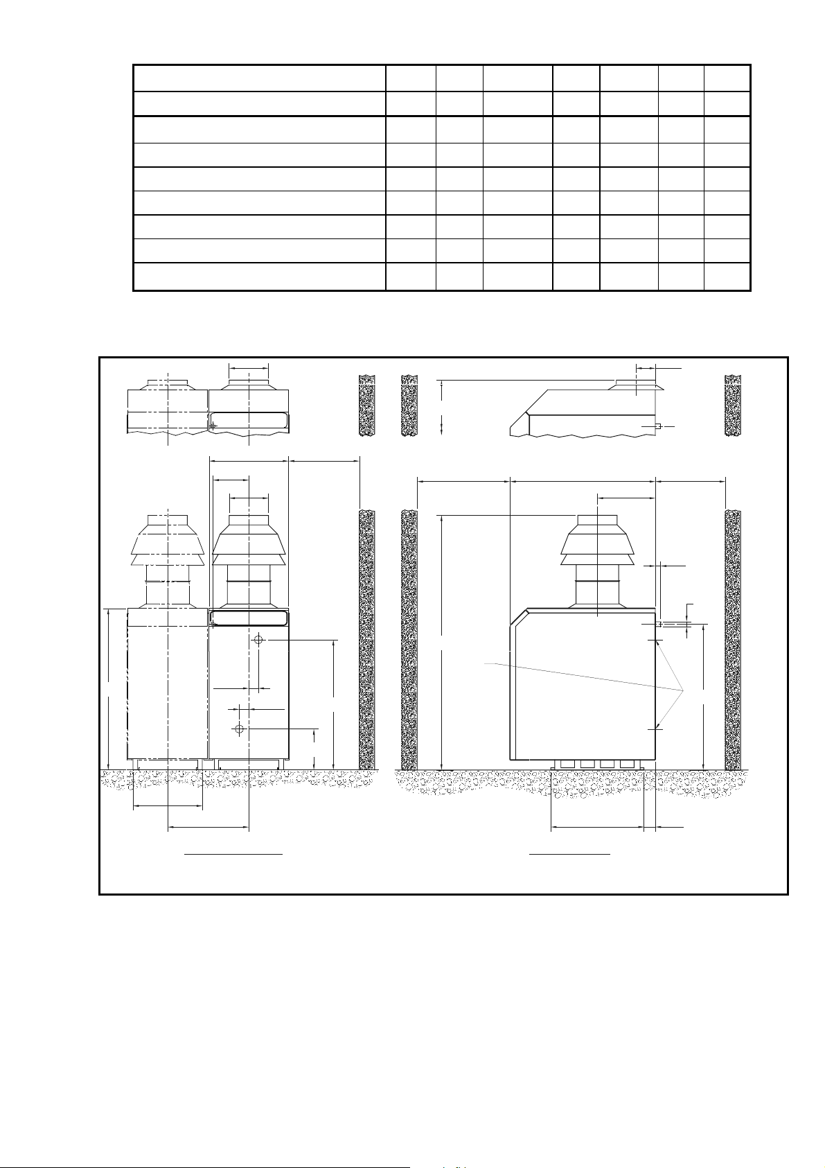
Figure No. 9 - Boiler Dimensions/Clearances.
A
Note! C = Classic model 40/50 40 60/70/80 70 95/105 100 120
I = Integra model
C
I
C
I
C
I
C
Approx. Dry Weight kg. 235 240 285 290 345 350 400
A - Boiler Height (Casing) mm. 870 1007 870 1195 1060 1195 1060
B - Flue height from floor mm. 1383 1035 1475 1126 1577 1201 1671
C - Flow Connection Height mm. 580 580 667 667 761 761 855
D - Gas Connection Height mm. 769 769 769 769 957 957 957
E - Gas Connection - (BS21) R¾ R¾ R¾ R¾ R1 R1 R1
F - Flue Outlet Dia. mm. (Nominal) 206 206 206 206 256 256 256
NOTE! The 533 centres relates to boilers close coupled in modular form. For stand-alone applications a
minimum of 150mm should be allowed between casings. (Space baskets 200mm apart).
235
F
532
GAS
B
460
RECOMMENDED
150 MIN
F
INTEGRA
954610 MIN 460 MIN
380
126
35
PPROX
E
GAS
FLOW
A
455
62.5
533 CRS
62.5
C
RET'N
269
FRONT VIEW
B
Rc2"
SIDE VIEW
FLOW
D
RETURN
612 74
HAMWORTHY HEATING LTD. PUREWELL PERMANENT IGNITION 500001090/B
21
Page 28
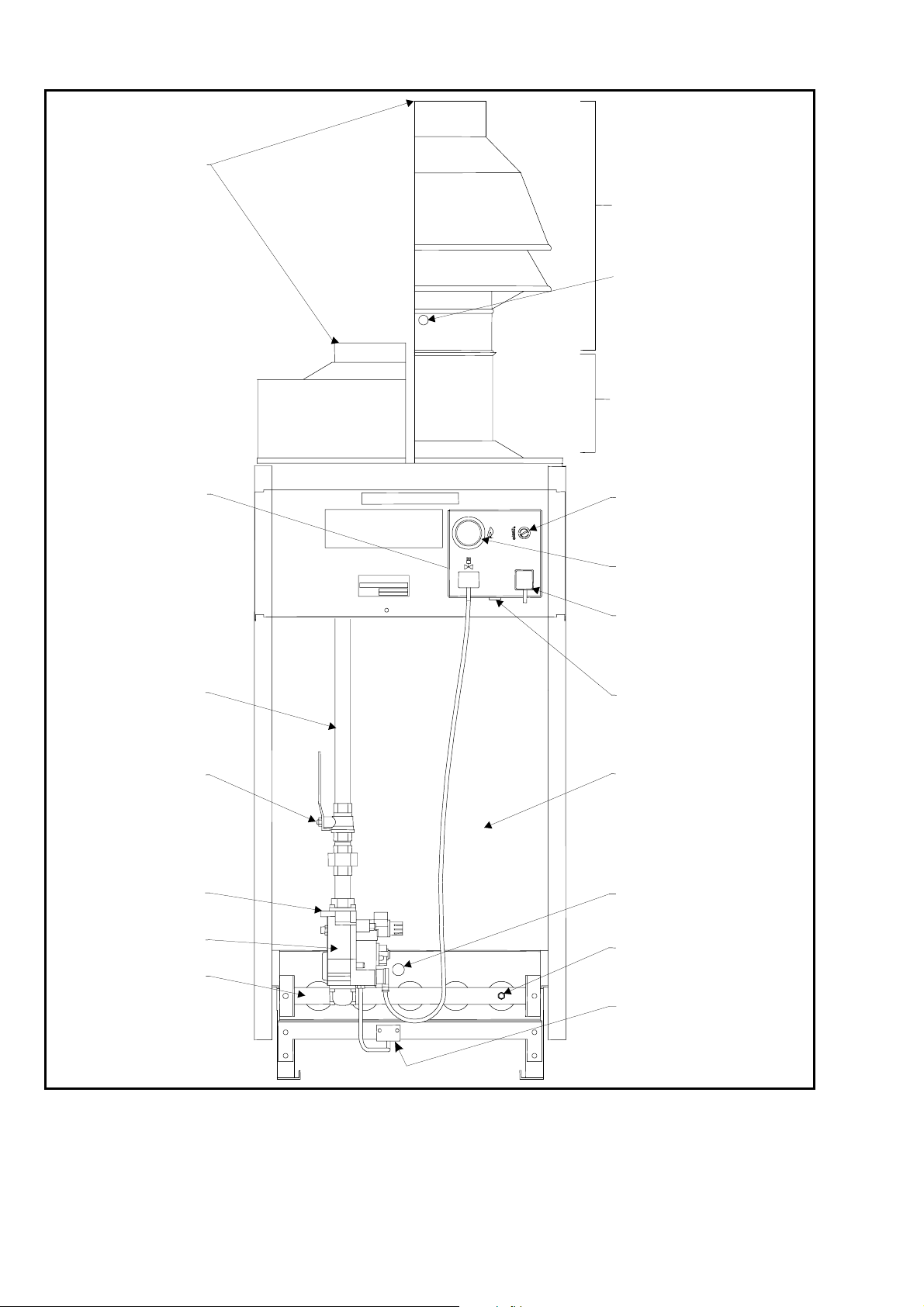
Figure No. 10 - General Layout (Front View).
A
r
A
FLUE SOCKET
INTEGRA CLASSIC
DRAUGHT
SSEMBLY
FLUE SAMPLING
POINT
PRIMARY FLUE
o
ON/OFF DAMPER
SSEMBLY
CONTROLS
PIEZO IGNITER
GAS VALVE
BURNER
GAS PIPE
GAS COCK
TEMPERATURE
(OVERHEAT
CONTROL
FUSED 3 PIN IEC
SUPPLY PLUG
ECO CONNECTOR
BOILER
VIEWING PORT
BURNER
TEST POINT
PILOT ASSEMBLY
HAMWORTHY HEATING LTD. PUREWELL PERMANENT IGNITION 500001090/B
22
Page 29

Figure No. 11 - Gas Flow in Pipes.
Purewell Boiler
Maximum length of gas pipe (Metres)
Output
Dia 20mm 25mm 40mm 50mm 65mm 80mm 100mm
40kW 1042-----
50kW - 25 180 820 - - -
60kW - 16 120 540 - - -
70kW - 11 85 380 - - -
80kW - - 62 280 900 - -
95kW - - 42 185 580 - -
105kW - - 33 145 470 - -
120kW - - 25 110 345 - -
160 (2 x 80kW) - - 12 56 180 - -
190 (2 x 95kW) - - - 38 120 750 -
210 (2 x 10⁵kW) - - - 30 96 600 -
240 (2 x 120kW) - - - 22 72 440 -
285 (3 x 95kW) - - - 15 47 290 -
315 (3 x 10⁵kW) - - - 11 37 235 -
360 (3 x 120kW) - - - - 27 170 810
380 (4 x 95kW) - - - - 24 150 730
420 (4 x 10⁵kW) - - - - 19 115 570
480 (4 x 120kW) - - - - 14 86 430
525 (5 x 10⁵kW) - - - - 11 71 340
600 (5 x 120kW) - - - - - 51 245
630 (6 x 10⁵kW) - - - - - 46 220
720 (6 x 120kW) - - - - - 34 165
The above table expresses pipe lengths from gas meter to appliance which will produce approx. 1mbar
pressure loss. This table must be used in conjunction with losses of various fittings fitted in the gas line shown
below.
Fitting Type 20mm 25mm 40mm 50mm 65mm 80mm 100mm
Per elbow 0.5m 0.5m 1.0m 1.5m 2.0m 2.5m 3.5m
Per Tee 0.5m 0.5m 1.0m 1.5m 2.0m 2.5m 3.5m
Per 90qBend
0.3m 0.3m 0.3m 0.5m 0.5m 1.0m 1.5m
For example: - 2 Purewell 120kW Boilers being fed by 65mm NB pipe with 6 elbows between gas meter and
boiler header can have a maximum length of 72m - (6 x 2m) = 60 metres run to achieve a 1mbar loss. Note!
Information above is based on IM/16.
HAMWORTHY HEATING LTD. PUREWELL PERMANENT IGNITION 500001090/B
23
Page 30
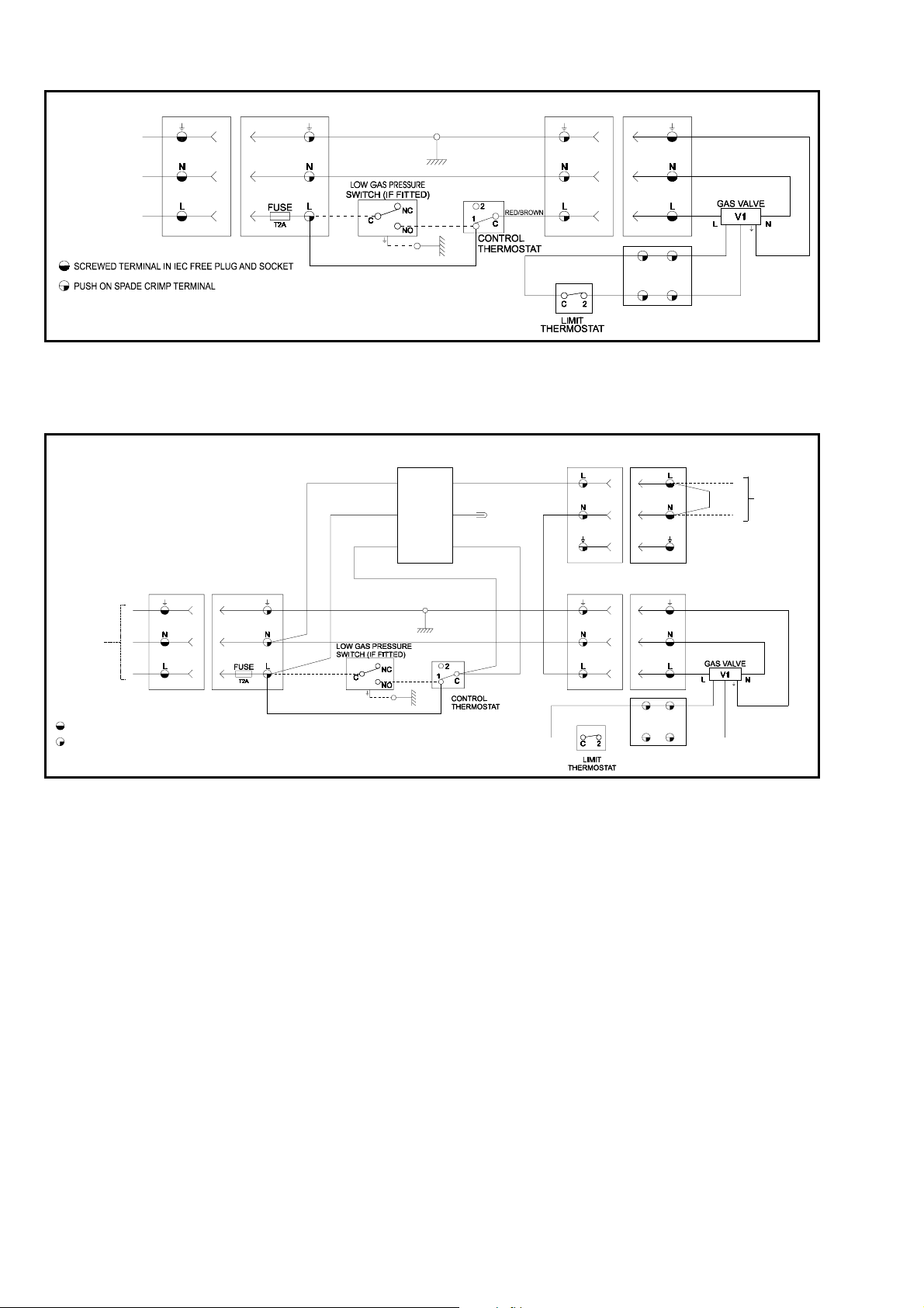
Figure No. 12 - Standard Controls Wiring Diagram Schematic.
230V ~ 50Hz
SUPPLY FROM
A FUS ED
ISOLATOR WITH
MINIMUM 3mm
CONTACT
SEPARATION IN
ALL POLES
KEY:-
MAINS
MAINS INLETFREE SOCKET
FUSED
GREEN/YELLOW GREEN/YELLOW
BLUE
BROWN
BROWN
GREEN/YELLOW
RED
YELLOW
GAS VALVE
SOCKET
YELLOW
GAS VALVE
PLUG
BULKHEAD
CONNECTOR
BROWN
GAS VALVE
ECO LEADS
Figure No. 12a - Standard Controls Wiring Diagram Schematic -(with On/Off Flue Damper).
REMOTE
RED/BROWN
ON/OFF LOOP
SOCKET
FLUE DAMPER
ACTUATOR
'1'
'2'
'3'
'S3'
'S2'
'S1'
REMOTE
ON/OFF LOOP
PLUG
GREEN/YELLOW
BLUE
RED/
BROWN
REMOTE ON/OFF
CONTROL LOOP
(REMOVE WIRE
LINK IF UTILISED)
MAINS
230V ~ 50Hz
SUPPLY FROM
A FUSED
ISOLATOR WITH
MINIMUM 3mm
CONTACT
SEPARATION IN
ALL POLES
KEY:-
SCREWED TERMINAL IN IEC FREE PLUG AND SOCKET
PUSH ON SPADE CRIMP TERMINAL
MAINS INLETFREE SOCKET
NOTE! Ensure all power supplies are completely isolated prior to working on the
electrical circuits of this appliance.
FUSED
GREEN/YELLOW GREEN/YELLOW
BROWN
BROWN
GREEN/YELLOW
RED
BLUE
YELLOW
GAS VALVE
OUTLET
YELLOW
GAS VALVE
PLUG
BULKHEAD
CONNECTOR
BROWN
GAS VALVE
ECO LEADS
GREEN/YELLOW
BLUE
HAMWORTHY HEATING LTD. PUREWELL PERMANENT IGNITION 500001090/B
24
Page 31
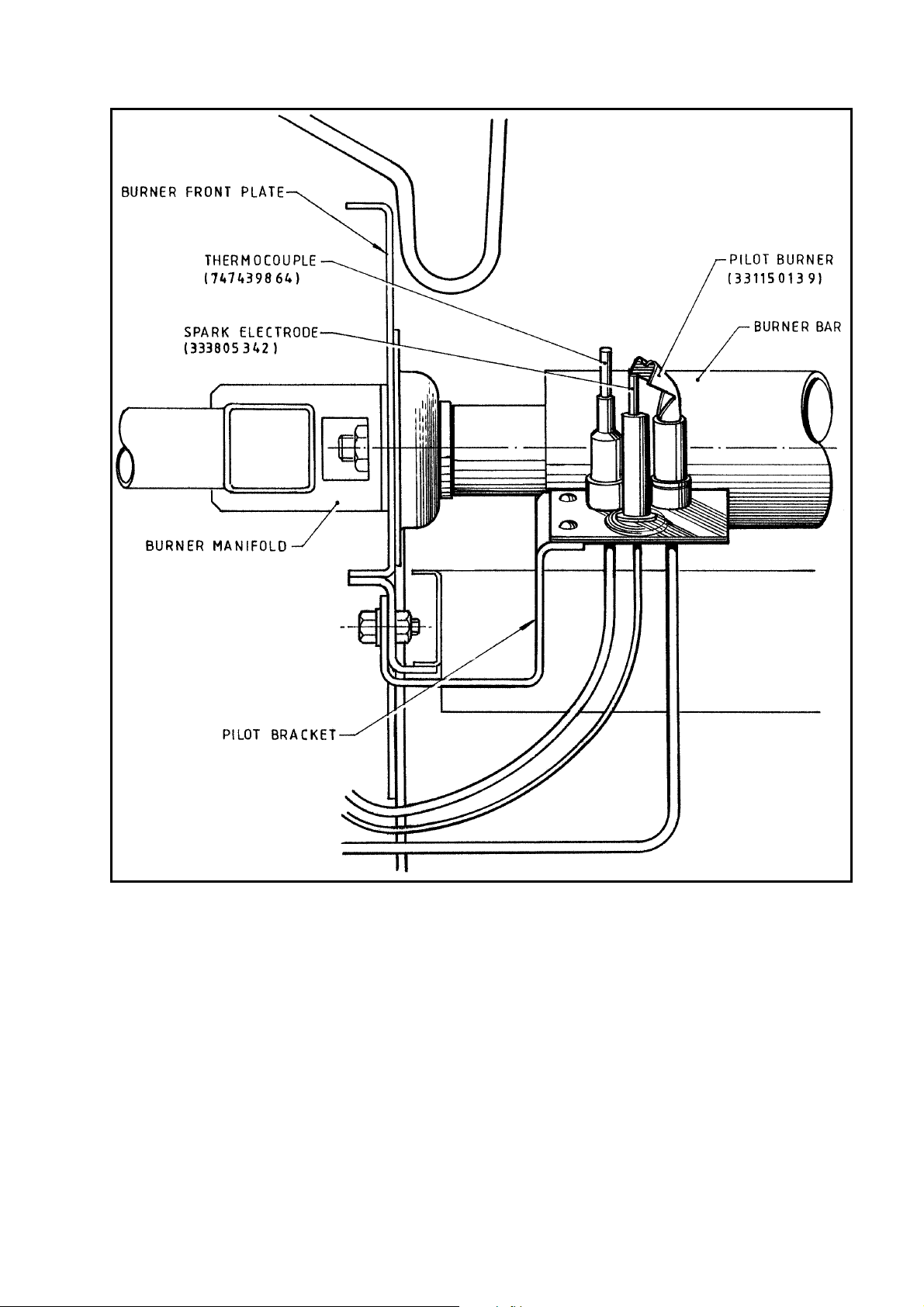
Figure No. 13 - Diagram of Igniter Assembly
HAMWORTHY HEATING LTD. PUREWELL PERMANENT IGNITION 500001090/B
25
Page 32

Figure No. 14 - Various Gas Valves Fitted to Purewell Boilers
a - Honeywell V4400 Series
b - Honeywell V4600 Series
c - Robertshaw 7000 Series
d - SIT NOVA Series
HAMWORTHY HEATING LTD. PUREWELL PERMANENT IGNITION 500001090/B
26
Page 33
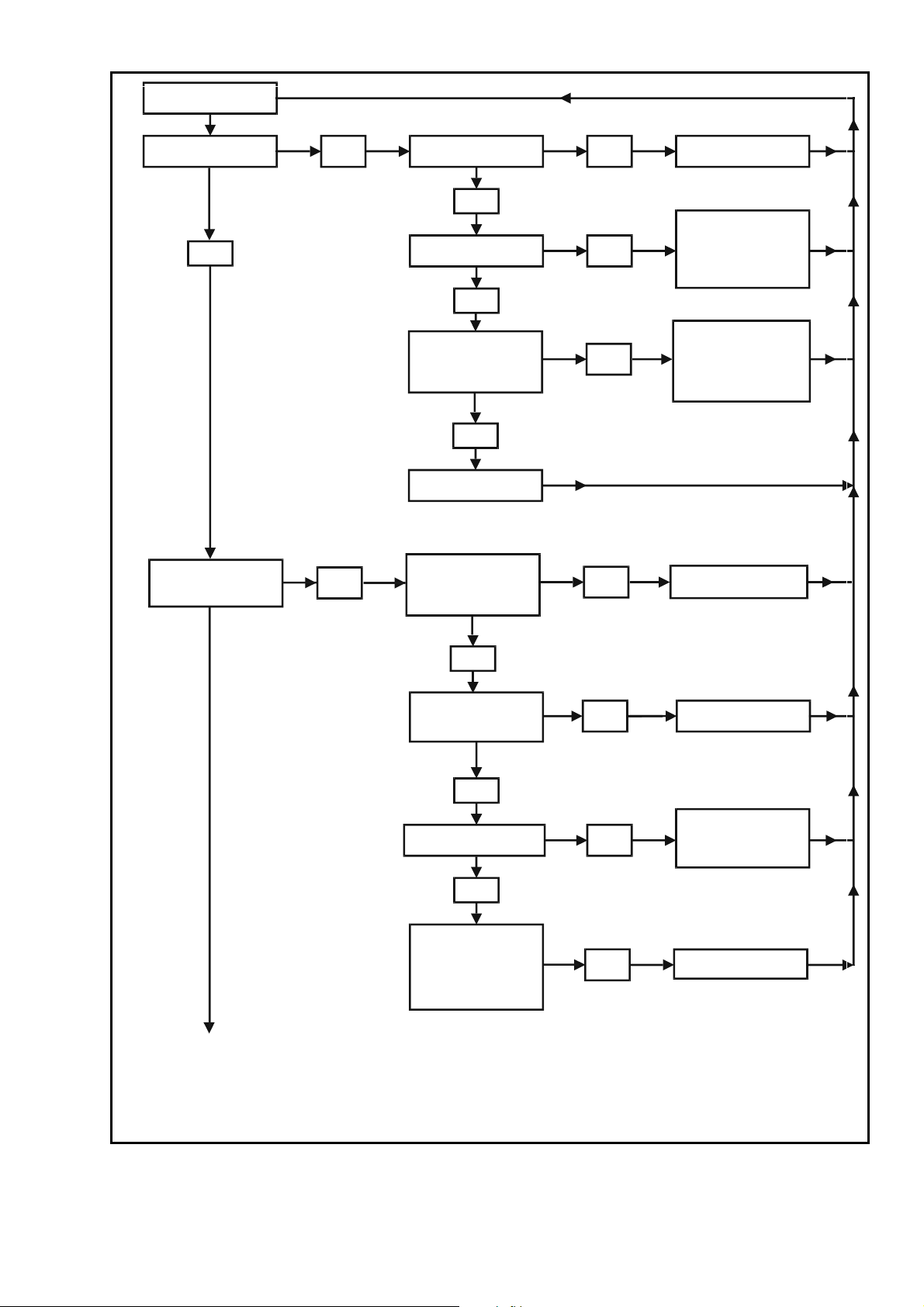
Figure No. 15 – Fault-Finding Procedures
Initiate start procedure
Is Pilot Alight ?
Yes
Does Pilot Remain ‘On’
When ‘Start’ Button is
Released ?
No
No
Is Gas Cock Open ?
Yes
Check Gas at Pilot ?
Yes
Check Spark Across
Electrode When
Operating Piezo ?
Yes
Repeat Pilot Lighting
Procedure
Are ECO Leads
Connected and Correctly
Fitted to the Temperature
Limiter ?
No
No
No
No
Open Gas Cock
Purge Pilot Line, Check
for Blocked Orifice in
Pilot Burner. Check Gas
Valve Start Button is
Fully Depressed.
Check Piezo Spark Igniter
is Operating Correctly.
Check Electrode Gap.
It Should Be 3 - 4 mm.
Check Spark Lead is
Connected Correctly.
Check and Clean as
Required.
Continued
on next page
Yes
Is Temperature Limiter
Pin (on Controls Panel)
Reset ?
Yes
Is Pilot Flame Sufficient
To Hold in Thermocouple ?
Yes
Check Thermocouple
Operation by Inserting a
mVolt (DC) Multi-Meter in
Parallel with ECO Lead.
Reading Should be at
least 8mVolts.
No
No
No
Reset Temperature
Limiter (Limit Stat).
Adjust Pilot Pressure
until Flame Envelopes
Thermocouple Tip by
Approximately 12mm.
Replace Thermocouple
HAMWORTHY HEATING LTD. PUREWELL PERMANENT IGNITION 500001090/B
27
Page 34
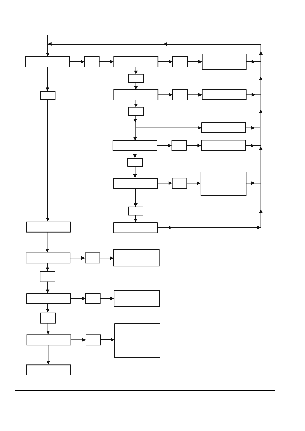
Figure No. 15a – Fault-Finding Procedures (Continued)
Continued from previous page
Main Gas Valve Lifts,
Lighting Main Burner.
Yes
No
Optional On/Off
Damper - Classic
models only
Is 230V Available at
Control Thermostat ?
Ye s
Is Thermostat Calling
for Heat ?
Ye s
LPG models only
Is the Remote Control
Link Secure ?
Ye s
Is There Power at the
Gas Valve ?
No
No
No
No
Check Power Supply.
Check 2A Fuse in
IEC Socket.
Check System Controls.
Produce Demand.
Check Operation of Low
Gas Pressure Switch
Close Remote Control
Link Circuit.
Check the Damper
Electrical Connections
and Mechanism. Check
the Gas Valve Plug
and Wiring.
Normal Run
Stop.
Boiler Cycles On/Off
Rapidly ?
No
Boiler Overheats,
System remains Cool ?
No
Boiler Noisy?
Yes
Ye s
Ye s
Ye s
Replace Gas Valve.
Thermostat Faulty. Poor
Circulation due to Faulty
Pump or Air Pockets.
Insufficient Circulation. Air
Pockets Restricting
Circulation. Pump Failure.
Insufficient Circulation.
Thermostat Set too High.
Faulty Thermostat. Boiler
Waterways Scaled Up.
Gas Valve Faulty. Gas
Pressure Incorrect, Check
Manifold Pressure.
Boiler is Operating
Satisfactorily !
28
HAMWORTHY HEATING LTD. PUREWELL PERMANENT IGNITION 500001090/B
Page 35
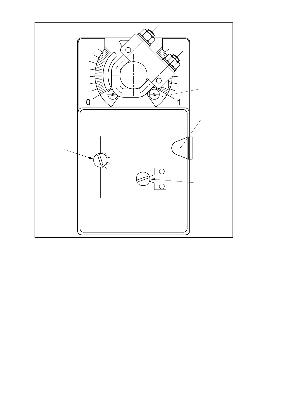
Figure No. 16 – Damper Actuator Motor
POSITION
SWITCH DIAL
SHOWING
SETTING
POSITION
.2
0
.4
.6
1
.8
ACTUATOR
END STOP
MANUAL
OPERATION
PUSH-BUTTON
ML
ACTUATOR
MR
REVERSING
SWITCH
HAMWORTHY HEATING LTD. PUREWELL PERMANENT IGNITION 500001090/B
29
Page 36

APPENDIX ‘A’ TO INSTALLER’S GUIDE
INFORMATION RELATING TO PROPANE FIRING
NOTE!
LPG FUELS - IT IS STRONGLY RECOMMENDED THAT, ON LPG INSTALLATIONS, GAS DETECTION
EQUIPMENT BE FITTED. THIS EQUIPMENT SHOULD BE POSITIONED NEAR THE BOILER AND AT LOW
LEVEL. IT IS ALSO IMPORTANT THAT THE SPACE HOUSING THE BOILER IS ADEQUATELY
VENTILATED AT HIGH AND LOW LEVEL. REFER TO MAIN INSTALLER’S GUIDE.
1.0 INTRODUCTION
Performance and General Data Information table
below.
The operation of the Purewell range of boilers on
LPG-Propane (3
Natural Gas (2
rd
family)I3P is similar to that on
nd
family)I2H and the design and
installation details described in the main body of the
c) The nominal gas inlet pressure for propane
should be 37mbar.
d) Relevant labels are replaced to indicate the
appropriate gas for which the boiler is set up to fire.
installer’s guide should be followed. There are
however, differences in the construction and setting
of the propane fired boiler which are as follows: -
The following tables and paragraphs, using the
same numbering system as the main installer’s
guide, highlight the different values and procedures
a) The pilot injector marked 56/42A for Natural Gas
is replaced with an injector for Propane, marked
to be used when firing propane, and should be
used in conjunction with the Main Installer’s Guide.
0.23P (perm/pilot only).
b) The main gas injectors (located in the gas
manifold) are replaced with those detailed the
Performance and General Data Information
Model
GENERAL DATA 40 50 60 70 80 95 100 105 120
Boiler Input kW (Gross) 49.3 63.4 74.5 88.4 101.0 120.0 126.0 132.0 150.0
Boiler Input kW (Net) 45.4 58.4 68.6 81.4 93.0 110.5 116.0 121.6 138.1
Boiler Output kW 40 50 60 70 80 95 100 105 120
Gas flow rate m3/h 1.9 2.4 2.8 3.3 3.8 4.5 4.7 5.0 5.7
kg/h 3.5 4.6 5.3 6.3 7.2 8.6 9.0 9.5 10.7
Gas manifold pressure mbar 15 15 15 15 17 29 23 25 24
FLUE DATA
Approx. flue gas temp qC
180 190 190 200 210 200 200 210 190
Approx. flue gas vol. @ 68 83 81 97 110 132 147 147 175
9% CO2 & NTP. m3/h
CO2 % 8.0 9.0 11.0 11.0 11.0 11.0 10.0 11.5 10.0
GAS DATA
Nominal gas inlet pressure mbar 37
Maximum gas inlet pressure mbar 45
Injector marking/ Dia. mm 2.1 2.3 2.6 2.8 2.9 2.4 2.7 2.7 2.9
Pilot burner(Perm/Pilot) Q349A-1034 (with 0.23P injector)
11.5 BOILER CHECKS PRIOR TO LIGHTING
pressure to fall. The switch should operate at
approximately 20mbar - noted on the multi-meter.
Ensure that the gas supply is connected but turned
to the ‘OFF’ position. Remove the cover on the low
gas pressure switch and connect a multi-meter
11.5.1 Gas Pressure Adjustment
across terminals ‘C & NO’ - to measure circuit
continuity.
After approximately 30 minutes of normal firing,
connecting a manometer to test point on the
Connect a manometer suitable for 50mbar to the
pressure tapping on the switch body and gradually
turn ‘ON’ the gas supply. The switch should operate
at approximately 20mbar - noted on the multi-
manifold should check the manifold gas pressure.
Minor adjustments to the appliance governor may
be necessary to correct for site gas pressure
conditions.
meter.
NOTE: The above is a first order check. Final
Turn ‘OFF’ the gas supply and undo the pressure
setting must be made using a gas meter.
test point on the gas valve inlet and allow the gas
HAMWORTHY HEATING LTD. PUREWELL PERMANENT IGNITION 500001090/B
30
Page 37
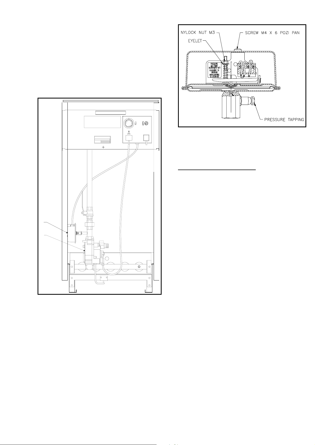
11.5.2 Combustion Checks
A flue gas sampling point is provided in the front
boiler casing (see Figure No. 10). To check
combustion take a flue gas sample from each
module test point and for reference CO
measurements should be between 8.0% and 11.5%
or 9.0 to 4.0% O
(dependant upon model). Normal
2
CO levels should not exceed 200ppm.
NOTE: All the above measurements refer to dry
flue gas samples.
Gas Pressure Switch Location
HAMWORTHY HEATING LIMITED
PUREWELL PERMANENT IGNITON
BOILER CONTROL PANEL
230V ~ 50Hz
35W MAX.
Gas Pressure Switch Adjustment
2
With the cover removed, turn the M3 nut clockwise
to increase the set point and vice-versa. Seal the
adjuster after setting.
15.0 RECOMMENDED SPARES
I
II
Key: I - Gas Pressure Switch
II - Main Gas Valves
MECHANICAL ITEMS PART No.
Pilot Injector - Propane....................... 331101850
(marked 0.23P)
Low Gas Pressure Switch................... 339009477
For electrical connections to the Low Gas Pressure
Switch, see Figure 12.
HAMWORTHY HEATING LTD. PUREWELL PERMANENT IGNITION 500001090/B
31
Page 38

INSTALLER SITE ADDRESS
DATE OF COMMISSIONING:
USEFUL USER INFORMATION
BOILER
TYPE
BOILER
SIZE(S)
UNIT
NO(S).
SERIAL NO(S). FLUE
NOTES:
HAMWORTHY HEATING LTD. PUREWELL PERMANENT IGNITION 500001090/B
32
Page 39

Hamworthy Heating
Accredited Agents
North West England North East England
Gillies Modular Services Allison Heating Products
210-218 New Chester Road 17 Beach Road
Birkenhead South Shields
Merseyside L41 9BG Tyne & Wear NE33 2QH
Tel: 0151 666 1030 Tel: 0191 455 7898
Fax: 0151 647 8101 Fax: 0191 455 7899
Scotland
McDowall Modular Services
14/46 Lomond Street
Glasgow G22 6JZ
Tel: 0141 336 8795
Fax: 0141 336 8954
Hamworthy Heating
Accredited Distributors
Southern Ireland Northern Ireland
HEVAC Limited HVAC Supplies Limited
Muirfield Drive Unit 2 Antrim Line Business Park
Naas Road Sentry Lane
Dublin 12 Newtownabbey
Ireland BT3 8XX
Tel: 003531 14191919 Tel:02890849826
Fax: 00353114584806 Fax:02890847443
For all other areas, or for further advice, please contact Hamworthy Heating head
office service department in Poole, telephone 01202 6625
Page 40

Hamworthy Heating
Connect direct for better service ....
Direct Dial Telephone Numbers
POOLE OFFICE
HAMWORTHY HEATING LIMITED
Fleets Corner, Poole, Dorset, BH17 0HH. England.
Main Switchboard tel: 01202 662500.
Customer Services fax: 01202 665111.
Boilers x controllers x water heaters x pressurisation sets x cold water boosters
GENERAL ENQUIRIES............................................ 01202 662552
For general enquiries on products and services available from Hamworthy Heating, our Customer Liaison staff are on
hand to answer your questions.
QUOTATIONS.......................................................... 01202 662552
Hamworthy Heating provide an efficient pricing and quotation service. Our Customer Liaison staff will also be pleased
to arrange for one of our Sales Engineers or Authorised Sales Agents, to visit you to discuss your needs in person, and
offer expert technical and commercial advice on heating, flue and water systems.
TECHNICAL ENQUIRIES.................................. 01202 662527/662528
For problems of a technical nature and further product support, our Technical Applications Engineers offer specifiers
and contractors advice on all aspects of equipment application, configuration and capability.
ORDER ENQUIRIES ......................................... 01202 662518
For an efficient response to order acknowledgement and administrative queries, contact our order processing team.
DELIVERY ENQUIRIES .................................... 01202 662515/662504
Deliveries from Hamworthy Heating arrive direct from the factory on a vehicle equipped with a tail-lift for ease of offloading to ground level. Our contracts team will progress despatch and liaise individual delivery arrangements.
SPARE PARTS................................................. 01202 662525
A comprehensive spare parts service is operated from our factory in Poole, providing replacement parts for both
current and discontinued products. Please contact our spares team, providing details of product type, serial number,
model and part requirements wherever possible.
SERVICE DEPARTMENT.................................. 01202 662555
At Hamworthy Heating we employ our own skilled service engineers who are trained to work on all of our products. Our
National coverage of all UK mainland sites is supported by a network of Authorised Service Agents who can provide
the same high level of service and product expertise.
EXPORT ........................................................... +44 (0)1202 662514
Hamworthy Heating has an expanding global network of distributors and partner companies providing local contact,
product and after sales service. This network currently includes Italy, Benelux, Germany, Baltic States, Finland,
Russia, Poland, Australia, South Africa, Hong Kong and China.
BIRMINGHAM OFFICE
HAMWORTHY HEATING LIMITED
Shady Lane, Great Barr, Birmingham, B44 9ER
Main Switchboard tel: 0121 360 7000.
Customer Services fax: 0121 325 0890.
Flue components x design service x bespoke manufacture x installation
FLUE PRODUCTS (ALL ENQUIRIES) .................... 0121 360 7000
Our factory in Birmingham offers a comprehensive range of flue products from stock, or alternatively provides a full
design and installation service incorporating sizing, site survey and drawings for approval prior to manufacture.
Associate Companies, Offices and Agents throughout the World.
Hamworthy reserves the right to mak e changes and improvements which ma y neces sitate alteration to the specificat ion without prior notice.
 Loading...