


Dorchester DR-SA Range
of Hot Water Storage Heaters
Open Flue, Direct Gas Fired Hot Water
Storage Heaters with Automatic Ignition
for Domestic Hot Water Installations
Installation, Commissioning
and Servicing Instructions
DORCHESTER DR-SA 16, 19 MODELS
NATURAL GAS I
LPG I
2H
3+
NOTE: THESE INSTRUCTIONS MUST BE READ AND UNDERSTOOD BEFORE INSTALLING,
COMMISSIONING, OPERATING OR SERVICING EQUIPMENT.
THIS WATER HEATER IS FOR USE ON GROUP H NATURAL GAS (2ND FAMILY) I2H OR
LPG (3RD FAMILY) I3+. PLEASE ENSURE RELEVANT INFORMATION REQUIRED WITHIN
DOCUMENT IS FOUND RELATING TO SPECIFIC GAS TO BE FIRED BEFORE FIRING
HEATER.
THIS WATER HEATER COMPLIES WITH ALL RELEVANT EUROPEAN DIRECTIVES.
PUBLICATION NO. 500001135
ISSUE ‘F’
APRIL 2012

2

3
CONTENTS PAGE
1. GENERAL 4
1.1 Description .............................................................................................................................................................4
1.1.1 Delivery ..................................................................................................................................................................4
1.1.2 Options ...................................................................................................................................................................4
1.2 Technical description ..............................................................................................................................................6
1.2.1 Gas control valve ...................................................................................................................................................6
1.2.2 Control panel ..........................................................................................................................................................6
1.2.3 Operation of the water heater ................................................................................................................................6
1.2.4 Combustion products discharge safety device.......................................................................................................7
1.3 Technical information .............................................................................................................................................7
1.3.1 Dimensions ............................................................................................................................................................7
1.3.2 Technical data ........................................................................................................................................................8
2. FOR THE INSTALLER 9
2.1 Installation ..............................................................................................................................................................9
2.1.1 Regulations and Related Documents.....................................................................................................................9
2.1.2 Water circulation system ......................................................................................................................................10
2.1.3 Gas connection ....................................................................................................................................................12
2.1.4 Draught diverter ...................................................................................................................................................12
2.1.5 Flue system ..........................................................................................................................................................12
2.1.6 Electrical connection ............................................................................................................................................12
2.2 Commissioning .....................................................................................................................................................12
2.3 Removing and replacing the control panel front cover .........................................................................................13
2.4 Setting the gas pressure ......................................................................................................................................13
2.5 Temperature regulation ........................................................................................................................................14
2.6 Converting to another type of gas ........................................................................................................................14
2.7 Maintenance.........................................................................................................................................................14
2.7.1 Sacricial anode ...................................................................................................................................................14
2.7.2 Cleaning ...............................................................................................................................................................14
2.7.3 Inspection of the internal waterside surfaces .......................................................................................................14
2.7.4 Spare parts...........................................................................................................................................................15
2.8 Condensation .......................................................................................................................................................15
2.9 Important warning ................................................................................................................................................15
3. FOR THE USER 15
3.1 Instructions for use ...............................................................................................................................................15
3.2 Fault nding..........................................................................................................................................................16
APPENDIX 1 ............................................................................................................................................................................17
Connection diagram Dorchester DR-SA 16 & 19 .....................................................................................................................17

4
1. GENERAL
1.1 Description
Construction of the Dorchester DR-SA heaters is in
accordance with the European standards for gas red
water heaters for sanitary use (EN 89). The heaters
comply with the European Directive for Gas Appliances
and are permitted to bear the CE mark.
1.1.2 Options
The Dorchester DR-SA heaters can be supplied with
additional variations, either ready tted or for on-site
assembly.
a) LPG – The heaters can be supplied adjusted for use
on propane or butane – see section 2.7. It is important
that the heater is correctly adjusted for the gas to be
red.
It is an open-ue appliance without a fan and with
combustion products discharge safety device (category
B
). The heaters are suitable for use with a working
11BS
pressure of up to 8 bar but on un-vented systems this is
limited to 5.5 bar due to the pre-set of the un-vented kit.
The cylindrical tank is made from sheet steel containing
one vertically placed ue tube.
For protection against corrosion, the inside of the tank is
glass lined. The tank is also tted with one magnesium
anode for extra protection against corrosion. A thick
insulating layer between the tank and the steel jacket
helps to reduce heat loss.
When the heater is completely lled with water, the
system is under continuous water pressure. When hot
water is drained from the heater, cold water immediately
enters the heater. For effective heat transfer, four ue
bafes are included in the ue tube. Heat from the ue
gases is transferred to the water by means of radiation
and convection. The ue gases are discharged by natural
thermal draught (see gure 1).
Dead legs on a hot water installation are undesirable.
Where possible they must be avoided. Where the
inclusion on the system of a dead leg is unavoidable the
following restrictions must be applied:
- For pipes not exceeding 19 mm inside diameter;
maximum length of dead leg permitted 12.0 metres;
- For pipes exceeding 19 mm but not exceeding
25 mm inside diameter; maximum length of dead leg
7.5 metres;
- For pipes with an inside diameter exceeding 25 mm;
maximum dead leg 3.0 metres.
b) Un-vented supply – The heaters can be supplied
with a purpose designed and sized un-vented kit
comprising pressure reducing valve, non-return
valve, expansion vessel, expansion relief valve and
temperature/pressure relief valve, to enable the heater
to be coupled directly to the mains water.
c) Top to Bottom Recirculation – In order to give
enhanced temperature control to aid compliance with
HSE guidance and Health Technical Memoranda,
a pump circulation kit can be supplied comprising
230 volt single phase pump, pipe work and sufcient
ttings to connect between the hot water ow and the
bottom drain connection.
d) Electrical Anode Protection - The electrical
conductivity of water, measured in micro siemens per
centimetre, is an important parameter in sacricial
anode protection. The lower the value, the less
effective the magnesium anode becomes.
In areas where the conductivity is likely to be less than
200 ¼ µ/cm, it is recommended that the magnesium
anode be replaced with an electrically powered inert
anode that requires an uninterrupted electrical supply
to its control unit. A kit (normally factory tted) can be
supplied comprising anode, additional control panel
and interconnecting wiring.
1.1.1 Delivery
All Dorchester heaters are factory assembled and
delivered individually packed and shrouded in polythene
on a wooden pallet. Within the packaging, wrapped
separately is the draught diverter complete with the
combustion products discharge safety device attached by
its capillary sensor. A separate package is included that
contains the installers kit, a ½” manual gas shut off valve,
a ¾” drain valve with Tee and plug, a special ¾” NPT to
BSP threaded nipple and a plastic cover for the drain cutout in the casing.

5
11
14
15
16
17
1
2
3
4
5
6
9
7
13
10
12
8
AOS 1120
Figure 1 - Cross-section of the heater
1) Draught diverter
2) Hot water outlet
3) Insulation
4) Flue tube
5) Glass lined tank
6) Gas control valve
7) Control panel
8) Inspection cover plate
9) Intermittent pilot burner and ame probe
10) Cold-water inlet (c/w inlet tube)
11) Combustion products discharge safety device.
12) T&P valve connection
13) Outer casing
14) Flue bafe
15) Magnesium anode
16) Drain valve and secondary return connection
17) Main burner.

6
1.2 Technical description
1129
1.2.3 Operation of the water heater
1.2.1 Gas control valve
The water heater is equipped with a gas control valve
c/w burner control that regulates the ow of gas to the
burner. To improve ignition the opening mechanism of
the gas control valve is tted with a delay (softlite). The
gas control valve is suitable for gases of the second and
third family. The maximum inlet pressure is 60 mbar. The
pilot system has an automatic spark ignition that make
sure that the burner ignites consistently when there is a
demand for hot water.
1.2.2 Control panel
The temperature control for the water heater is housed
in the control panel (See gure 2). For safety reasons,
heaters are tted with two thermostats: a control
thermostat is adjustable between 40°C and 80°C and a
safety thermostat is pre-set to 90°C. The control panel
is also tted with an ON/OFF switch (I/0). At setting “I”,
the gas control is activated on the basis of heat demand
from the control thermostat. At setting “0” the heater is
switched off.
Normal operation
When there is a demand for heat a waiting period
of about 1 second elapses before the built-in spark
generator and pilot gas valve are switched on. The
ignition spark lights the pilot burner and the ame probe
detects the resulting ame. Almost immediately after the
pilot ame is detected, sparking stops and the main gas
valve is opened. The pilot ame lights the main burner.
The unit is now in operation. When the water in the unit
reaches the set temperature the thermostat switches the
burner off.
Ignition failure
If the ame is not established within the safety period of
25 seconds the automatic ignition controller locks out.
The lamp on the reset button in the control panel shows a
lockout when lit. Pushing the reset button must manually
reset the heater. If the ame is lost during normal run, the
automatic ignition controller repeats the start sequence.
Figure 2 - Top view of the heater
A) Hot water outlet
B) Cold water inlet
1) Electrical connection
2) ON/OFF switch
3) Ignition controller reset button
4) Control thermostat knob
5) Safety thermostat reset button.
7
1.2.4 Combustion products discharge safety
device
The heater has been tted with a combustion products
discharge safety device. It is the function of the safety
device to prevent ue gases from the water heater
entering the room where the water heater has been
placed, instead of passing through the ue to outside
atmosphere. The gas supply is disconnected as soon as
hot gases owing over the sensor activate the device.
After the cause of the re-entry of ue gases has been
traced the device can be put back into operation by
pressing its reset button. If this failure occurs frequently,
this indicates that the ue suffers from down draught
conditions. It is recommended that a competent person
carry out the necessary remedial action.
Important
The combustion products discharge safety device must
never be put out of operation. Re-entry of ue gases to
the building could be harmful and cause poisoning or
death.
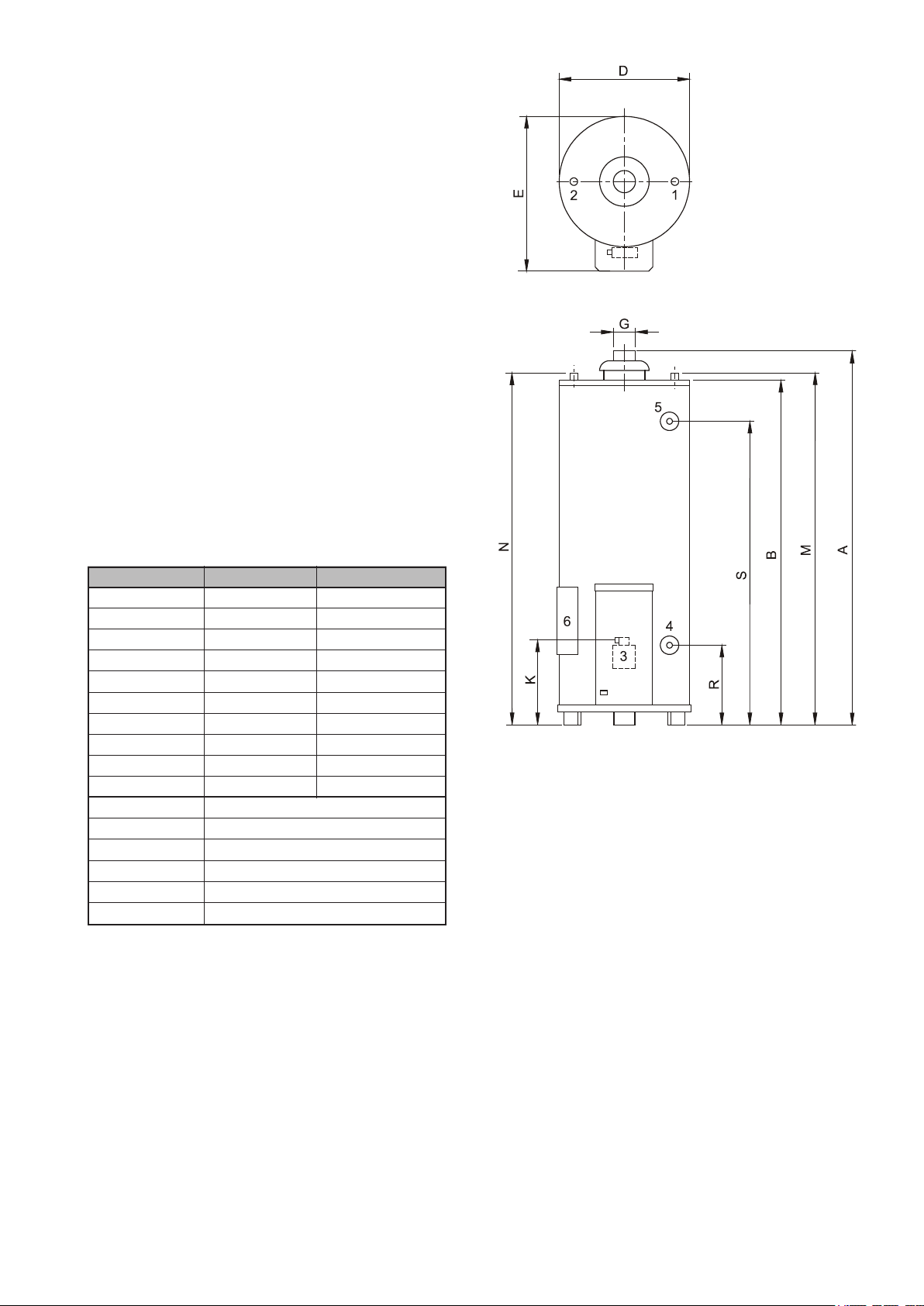
1.3 Technical information
1.3.1 Dimensions
The ue pipe must at least have the same diameter as
the spigot on the water heater (dimension G).
Dimensions DR-SA 16 DR-SA 19
A 1585 1780
B 1450 1640
D 645 675
E 770 775
G 130 130
K 340 340
M 1505 1685
N 1505 1685
R 285 285
S 1280 1460
1 Cold water inlet
2 Hot water outlet
3 Gas control valve
4 Drain valve
5 T&P valve tapping
6 Access door opening
All dimensions are given in mm. (rounded off to 5mm).
See gure 3.
Figure 3 - Dimensions
1) Cold water inlet
2) Hot water outlet
3) Gas control valve
4) Drain valve
5) T&P valve tapping
6) Access door opening

8
1.3.2 Technical data
Device category II2H3+
Description Unit DR-SA 16 DR-SA 19
DATA G20 – 20 mbar:
Nominal output kW 18.9 20.1
Nominal load (gross) kW 24.7 26.2
Supply pressure (G20) mbar 20 20
Burner pressure (G20) mbar 12.0 7.9
Gas consumption (G20)* m
Diameter main orice (G20) mm 3.90 4.50
Diameter pilot orice (G20) mm 0.56 / 0.41 0.56 / 0.41
Heating time ∆T = 45 K min 43 55
DATA G30 – 30 mbar:
Nominal output kW 18.9 20.1
Nominal load (gross) kW 24.1 25.6
Supply pressure (G30) mbar 30 30
Gas consumption (G30)* kg/h 1.8 1.9
Diameter main orice (G30) mm 2.30 2.35
Diameter pilot orice (G30) mm 0.23 0.23
Heating time ∆T = 45 K min 43 55
3
/h 2.4 2.5
DATA G31 – 37 mbar:
Nominal output kW 17.6 19.1
Nominal load (gross) kW 22.5 24.5
Supply pressure (G31) mbar 37 37
Gas consumption (G31)* kg/h 1.6 1.8
Diameter main orice (G31) mm 2.30 2.35
Diameter pilot orice (G31) mm 0.23 0.23
Heating time ∆T = 45 K min 43 55
GENERAL:
Storage capacity litres 278 372
Water connections ** 1-11.5 NPT 1¼-11.5 NPT
Gas connection Rp 1/
2
Rp 1/
2
Drain valve ¾”-14NPT ¾”-14NPT
Anode ¾”-14NPT ¾”-14NPT
T&P-plug ¾”-14NPT ¾”-14NPT
Maximum operating pressure bar 8 8
Maximum operating pressure un-vented bar 5,5 5,5
Nominal operating pressure un-vented bar 3,5 3,5
Empty weight kg 122 149
* Gas consumption at 1013,25 mbar and 15 °C
** For a leak proof connection to an NPT thread, a coupling with threads to ISO 228/1 can be used

9
Electrical connenction
Electrical supply Frequency Fuse
230 V AC 50 Hz 5 A
Ionisation current
The minimum ionisation current is 0.9 micro-Amperes DC.
Below this current the burner controller will assume no ame
is present. When in normal operation, the ionisation current
will be about 1.2 to 1.3 micro-Amperes DC when only the
pilot ame is burning.
(Adjust the main burner pressure to zero to be able to
measure under this condition).
With pilot and main burner in operation, the ionisation
current will be approx. 6.0 to 6.3 micro-Amperes DC.
Ionisation current can be measured by connecting a
universal meter in series with the connection to the ame
probe. Make sure meter is set for Direct Current. Alternating
Current gives no information about the system’s behaviour.
2. FOR THE INSTALLER
2.1 Installation
This water heater must be tted in a location that will permit
the provision of an approved ue system and adequate
ventilation.
A service clearance of 50 cm at the sides and rear of the
unit and 100 cm at the front of the unit must be allowed
for ease of servicing. Adequate distance must be allowed
between the top of the unit and any obstruction or ceiling to
allow the ue bafe and anode to be inspected, cleaned or,
in the case of the anode, replaced if necessary.
The water heater must stand on a level surface resistant
to heat, insulated in accordance with local by laws and
Building Regulations and with sufcient strength to support
the weight of the unit when full of water.
The heater must stand on its feet as supplied and the
space beneath the bottom casing kept clear as this is the
path for combustion air to enter the heater.
This water heater must not be installed in a bathroom,
bedroom or in a cupboard opening on to such rooms.
This water heater must not be installed in any area where
ammable materials are used or stored.
Insufcient ventilation may give rise to a risk of re,
explosion or suffocation. If in doubt consult the national
and local regulations governing the installation of gas
appliances or local gas service organisation.
2.1.1 Regulations and Related Documents
Gas Safety Installations and Use Regulations 1998,
(as amended). It is law that competent persons, in
accordance with the above regulations install all gas
appliances. Failure to install appliances correctly could
lead to prosecution. It is in your own interest, and that of
safety, to make sure that this law is complied with.
The installation of the boiler MUST be in accordance with
the relevant requirements of the Gas Safety Regulations,
Building Regulations, IEE Regulations and the Water
Supply (water ttings) Regulations.
The installation must also be in accordance with any
relevant requirements of the HSE, local gas region and
local authority and the relevant recommendations of the
following documents: -
British Standards
BS 6891: Specication for the installation of low-pressure
gas pipe work of up to 28 mm (R1) in domestic premises (2
family gas). For larger installations see IGE/UP/2 below.
BS 6798: Specication for installation of gas-red boilers
of rated input not exceeding 70 kW net.
BS 6644: Specication for installation of gas-red hot
water boilers of rated inputs between 70 kW and 1.8 MW
nd
(net) (2
BS 6700: Specication for design, installation, testing and
maintenance of services supplying water for domestic use
within buildings and their curtilages.
BS EN 806-2: Specication for installations inside
buildings conveying water for human consumption.
Part 2: Design.
BS 5546: Specication for installation of hot water
supplies for domestic purposes, using gas-red
appliances of rated input not exceeding 70 kW.
BS 5440: Installation and maintenance of ues and
ventilation for gas appliances of rated input not exceeding
70 kW net (1
Part 1: Flues. Part 2: Ventilation.
Institute of Gas Engineers and Managers Publications
IGE/UP/1 Soundness testing and purging of industrial and
commercial gas installations.
IGE/UP/1A Soundness testing and direct purging of
small low-pressure industrial and commercial natural gas
installations.
and 3rd family gases).
st
, 2nd and 3rd family gases).
nd
IGE/UP/2 Gas installation pipe work, boosters and
compressors on industrial and commercial premises.
IGE/UP/10 Installation of gas appliances in industrial and
commercial premises. Part 1: ued appliances.
CIBSE Publications:- “CIBSE Guide”
Section B4 : Water Service Systems.
Some chemicals produce vapours that can cause
rapid failure of main and pilot burners and storage
tanks if they are drawn into the combustion air
supply.

10
1105
Therefore if this water heater is to be used to supply
hot water to:
- hairdressers,
- dry cleaners,
- industrial degreasing processes or any other area
where compounds containing halogens are used
and stored, care must be taken that all primary and
secondary air is drawn from outside atmosphere free
of these contaminants. For further advice contact
Hamworthy Heating Limited.
2.1.2 Water circulation system
Dorchester water heaters are suitable for connection to
vented, un-vented and pumped pressurised systems.
In each case appropriate valves and ttings must be used
to make sure the system complies with the requirements
of the water ttings and appropriate
building regulations.
When tting it is essential the rules of ‘good practice’ are
applied at all stages of installation.
Water quality
The water heater is intended for heating drinking water.
The drinking water must comply with the regulations
governing drinking water for human consumption.
The table gives an overview of the specications.
Drain connection
The ttings for the drain are supplied in the installation kit
stuck to the wooden pallet. Select the hexagon nipple and
screw the thread nearest the groove in the nipple into the
heater drain opening using suitable sealant.
Fit the plastic cover over the nipple and push up tight to
the heater before assembling any other parts.
Note: the hexagon nipple is a thread adapter between
¾” NPT (nearest the groove cut into the hexagon) and ¾”
BSPT. Arrange the tee, plug and drain as shown in
gure 4. The actual orientation of the tee may depend on
whether a system return is required and whether a top to
bottom circulator kit is to be tted.
Vented systems (See gure 5)
Water composition
Hardness
(alkaline earth ions)
> 1.00 mmol/l:
• German hardness > 5.6 °dH
• French hardness > 10.0 °fH
• English hardness > 7.0 °eH
• > 100 mg/l CaCO3
Conductivity > 125 μS/cm
Acidity (pH value) 7.0 < pH value < 9.5
Note: If the water specications deviate from those
stated in the table, then the tank protection cannot be
guaranteed.
Important
Where water softeners are used on the hot water supply,
make sure that the hardness remains between 60 and
100 ppm CaCO3. In soft water areas with conductivity
less than 200 μS/cm, the electrically powered anode
system must be used.
Figure 5 –
Connection diagram vented systems
Figure 4
If the water heater is to be connected to a cold feed tank
or cistern the hot water supply pipe must include an open
vent. Ideally the vent pipe must be linked to a separate
tundish/drain or else to discharge over the cold water feed
tank. The cold feed cistern must have an actual capacity
of greater volume than the hourly recovery rate of the
water heater(s) that it supplies.
The minimum actual capacity is 50 gallons or 227 litres.
3) Safety valve
4) Stop valve
5) Non-return valve
6) Circulation pump
9) Drain valve
10) Manual Gas valve
11) Stop valve
14) Hot water draw off points
17) 3-way venting valve
A ) Cold water supply
B) Hot water outlet
C) Circulation pipe
D) Gas supply
E) Overow pipe

11
Un-vented system (see gure 6)
1119
To install a Dorchester water heater on an un-vented cold
water supply system a kit of valves and ttings (WRAS
approved) must be used. Installation must be carried out
generally as shown on gure 6.
Figure 6 - Connection diagram un-vented systems
1) Manual gas valve
2) Stop valve
3) Expansion vessel
4) T&P safety valve
5) Non return valve
6) Circulation pump
7) Drain valve
8) Pressure reducing valve
9) Expansion valve
A) Gas supply
B) Hot water delivery
C) Cold water inlet
D) Hot water taps
E) Return circulation

12
2.1.3 Gas connection
The gas supply to this appliance must be installed in
accordance with BS 6891 and IGE/ UP/1,1A and 2.
Fit the 1/2” manual gas shut off valve, supplied with this
unit, immediately before the gas control valve. No heat
or soldered joints must be applied in the vicinity of the
gas control valve, as this could cause damage to the
control. All connections and joints must be tested for gas
soundness.
2.1.4 Draught diverter
The draught diverter, supplied separately in the delivery
crate, MUST be tted to the top of the heater in an
unmodied condition before connecting the ue system.
The sensor of the combustion products discharge safety
device is pre-tted to the draught diverter so care must be
taken not to damage the capillary and thermostat. With
the sensor facing forward, place the draught diverter over
the ue tube and make sure the three legs engage with
the slots in the top casing.
To complete the installation of the combustion products
discharge safety device, remove the two screws from the
top casing, position the bracket with the pre-assembled
thermostat over the holes and re-apply screws.
Complete the electrical circuit by connecting the two-pin
plug to its appropriate socket on the top casing. If the
safety device operates, the heater will shut down and only
restart when the temperature of the sensor has dropped
sufciently for the button on the thermostat to be reset.
Important
The combustion products discharge safety device must
never be put out of operation.
Re-entry of ue gases to the building could be harmful
and cause poisoning or death.
2.1.5 Flue system
The water heater must be tted with a ue system
connected to the draught diverter. The ue pipe must rise
for at least 50 cm. vertically before the inclusion of any
bends. If a horizontal run of ue is required this must be
kept to the minimum length possible and incorporate a
rise of 6 cm. per metre of run.
The ue system must be self-supporting and incorporate
a removable section close to the heater to enable the
diverter and ue gas bafe to be removed for cleaning.
The materials used for the ue system must be non-
combustible, mechanically robust and resistant to internal
and external corrosion. Combustible materials in the
vicinity of the heater and ue shall not exceed 65°C
during heater operation. The ue shall not be closer
than 50 mm to any combustible material, except where
it passes through such material with a non-combustible
sleeve when the air gap may not be less than 25 mm.
All ues must terminate in free air space approx.
1,5 metres from any vertical surface of structure i.e.
chimneystacks, roof parapets, etc. If an existing chimney
or ue is to be used this must be swept clean and be
free of debris before an approved liner is installed and
connected to the water heater.
2.1.6 Electrical connection
An accredited electrical installation company must carry
out all electrical connections in accordance with IEE
regulations. The appliance must be connected to the
mains by means of a permanent electrical connection.
A Fused isolator must be tted between the permanent
connection and the water heater. The cable must have
3 cores of at least 1.0 mm
for the electrical supply are indicated by the symbol for
earth, N for neutral and L for live. Always check with a
voltage tester that the live and the neutral have been
connected correctly in the electrical supply. The electrical
supply must comply with the requirements below:
Electrical supply Frequency Fuse
230 V AC 50 Hz 5 A
The maximum power consumption is 25 W.
See appendix 1 electrical diagram for more information.
2
. The connecting terminals
2.2 Commissioning
Filling the water heater
1. Close the drain valve.
2. Open the cold-water stop valve to the water heater
and open all taps where hot water can be drained to
remove air. The water heater is lled as soon as cold
water ows from all taps.
3. Close all hot water taps.
Putting into operation
1. Check to see if the heater is lled with water
by running a little to waste from a hot water tap
connected to the system.
2. Make sure that the ON/OFF switch is in OFF position.
3. Make sure gas supply is fully purged of air and turn on
manual gas valve.
4. Switch the mains isolator to ‘ON’. Make sure that
power is correctly supplied to the unit. Use a voltage
tester to check that the live is to “L” and neutral to “N”.
(Flame detection is phase sensitive).
5. When rst starting, the controller can be in the ‘lock
out’ condition: depress the reset button to free the
control. (After manual reset, an extended pre-purge/
waiting time will occur).
6. Switch the ON/OFF switch into ON position. If the pilot
fails to ignite within 25 seconds the controls will go
to lock out and the reset button will need to be reset
(wait 15 seconds before attempting reset). It may be
necessary to repeat the lighting sequence a number
of times if all the air has not been purged from the gas
supply.
7. The main burner pressure must be checked once the
heater has operated for 10 to 20 minutes (see 2.4).
8. Set the temperature regulator to the required setting
(60°C is maximum recommended).
Note: If, during normal use, the reset button is
pressed, the gas valves will close and the automatic
ignition controller will start a new sequence after the
reset button is released.
Shut down
Note: The water heater must only be turned off when
hot water will not be required for an extended period (e.g.
holidays); otherwise it must be left on.
To shut down put the ON/OFF switch into OFF position.

13
2.3 Removing and replacing the control
panel front cover
Removing the cover (see gure 7)
1. Remove the screw at the top centre of the control
panel.
2. Push the cover upwards until the hooks at the lower
end clear the burner access opening and base tray.
3. Pull the lower end of the cover slightly forward.
4. Pull the cover down until the top edge is clear of the
control panel and then remove.
Replacing the cover (see gure 7)
1. Place the top of the cover inside the rim of the control
panel and push it up as far as possible.
2. Position the bottom hooks inside the burner access
opening and over the rim of the base tray.
3. Push the cover downwards until the lower hooks
engage and the top screw holes align.
4. Replace the screw in the top centre of the cover.
2.4 Setting the gas pressure
The gas pressure has been set to the correct value at the
factory but it must be checked again at commissioning
and during the once a year and every year maintenance
by adopting the following procedure:
1. Shut down the heater by switching the ON/OFF switch
to OFF.
2. If the control panel front cover is in place, remove it
(see 2.3).
3. Locate the lower pressure test point at the right hand
rear of the gas control valve. Loosen the screw a turn
and connect a manometer to measure the burner
pressure.
4. Switch the heater ‘ON’ and allow the burner to ignite
and stabilize.
5. Check the burner pressure for the gas being red,
against the requirement on the data plate or see
1.3.2. If necessary, reset the pressure by means of
the burner pressure adjusting screw located under
the metal cover screw adjacent to the pressure test
points. Turning it anti-clockwise reduces burner
pressure. Turning it clockwise increases burner
pressure.
6. Shut down the heater, remove the manometer,
tighten the pressure test point screw, and replace the
adjustment screw cover and the control panel front
cover.
7. Restart the heater.
Figure 7 - Removing and replacing the control panel
front cover

14
2.5 Temperature regulation
With the system operational, the amount of cold water that
is added is equal to the amount of hot water used. The gas
control valve automatically regulates the gas supply. The
main burner will ignite as soon as the thermostat senses a
reduction in water temperature. The main burner will shut
down as soon as the preset temperature is achieved. At
high water temperatures there is more scale build-up in the
heater. It is recommended therefore, that the thermostat is
set no higher than 60°C as the accumulation of scale will
be minimised.
2.6 Converting to another type of gas
Must conversion of the heater from natural gas to LPG
or vice versa be required, it must only be carried out by
a qualied competent person and only items from the
approved conversion kit must be used.
It will be necessary for the main and pilot injectors to be
changed to those sized for the gas to be red and for the
burner pressure to be adjusted (see 1.3.2).
Adopt the following procedure:
1. Turn the heater off. Close the manual gas shut off valve
and switch off the electrical supply at the local isolator.
2. Remove the burner assembly (see 2.8.2).
3. Replace the injectors with the correct injectors from
the conversion set.
4. Set the correct burner pressure for the gas to be red,
see sections 1.3.2 & 2.4.
For conversion from natural gas to LPG, the burner
pressure adjusting screw on the gas control valve
must be screwed in clockwise as far as it will go.
For conversion from LPG to natural gas, the burner
pressure adjusting screw must be backed off anticlockwise until the correct burner pressure is obtained.
2.7 Maintenance
Important: Due to the variable chemical nature of
distributed water supplies, it is recommended that, in
addition to the once a year and every year internal
inspection and cleaning, this heater is inspected for scale
deposition and anode loss within a maximum of three
months following initial commissioning and the frequency of
subsequent inspections adjusted accordingly.
Failure to install in accordance with the relevant Hamworthy
Heating Installers Guides and to carry out the above
recommendations may compromise appliance warranties.
Regular once a year and every year maintenance by a
qualied competent person is recommended. Although
cleaning of the ue is not necessary every year, it is
important that all controls and safety features are checked
for correct operation.
WARNING: Before proceeding with any maintenance,
isolate the electrical supply to the heater being serviced
and turn off the manual gas shut-off valve.
2.7.1 Sacricial anode
Note: On no account remove the magnesium anode
without checking to make sure that the heater is fully
isolated and the pressure removed.
1. Close the stop valve in the cold water supply pipe.
2. Open the nearest hot water tap in order to allow the
pressure to drop from the water heater and the pipes.
Run a hose to a convenient drain and open the drain
valve. Either drain sufcient water to enable the anode
to be removed or completely drain the heater if an
internal inspection is to be carried out.
3. The heater is tted with a single magnesium anode
that hangs vertically within the vessel and is located
behind the cold-water inlet. Release and unscrew
the anode with a suitable socket (27mm A/F) and
withdraw.
4. Check the anode and if it has been reduced
in diameter by 60% or more at any point on its
length it must be replaced. Always replace with an
anode of the correct size and type. When ordering
replacements always quote model and serial
numbers.
It is recommended that Permabond A131 WRAS
approved sealant or equivalent must be used to seal
the anode into the tank.
The anode must be in direct metal-to-metal contact
with the heater tank to protect it. It is therefore
recommended that electrical continuity between tank
and anode be checked with an appropriate instrument
immediately following replacement.
5. Check for water leaks.
2.7.2 Cleaning
WARNING: some of these items will be hot if the heater
has been ring immediately prior to disassembly.
1. Remove the control panel front cover, see section 2.3
and the inner front panel, see section 2.5,
2. Disconnect the gas burner feed pipe, the pilot burner
feed pipe and the two electrical cables (HT and ame
probe) from the gas control valve.
3. Remove the complete burner assembly.
4. Clean the burner with a soft brush.
5. Check the pilot burner, ignition electrode and ame
probe. Clean or replace as necessary.
6. Disconnect the ue adjacent to the draught diverter
(a maintenance joint must have been provided for
this purpose) and remove the draught diverter taking
care to disconnect the combustion products discharge
safety device. Withdraw the ue bafe vertically.
Check the combustion chamber, ue tube and ue
bafe and clean as required.
7. Re-assemble in the reverse order and check the
operation. If necessary the burner pressure must be
reset.
2.7.3 Inspection of the internal waterside
surfaces
Make sure the heater is fully empty. Remove the outer
inspection cover (two self tapping screws), the insulation
pad and clean out the door complete with sealing gasket (6
bolts ,13 mm socket). If deposits are apparent, they can be
ushed through the drain by a water jet applied through the
clean out opening.
The tank can also be chemically cleaned but it is advised
that a reputable chemical cleaning company carries this out.

15
Note: Do not use a metal scraper to remove deposits.
You will damage the glass lining.
After cleaning, replace the clean out door with new gasket
if required. Rell heater and check for leaks.
Note: The maintenance of the waterside of the system
may require additional cleaning and disinfecting before
being placed into service. Refer to BS 6700.
6. Make sure the manual gas shut off valve is open.
7. Switch the mains electricity supply to the heater ON.
Set the on/off switch on the heater to ON (1) and
adjust the control thermostat to the desired setting.
8. If the ignition controller rest button is illuminated, wait
30 seconds before pressing the reset button.
9. The heater will now light if heat is required.
2.7.4 Spare parts
To be able to order spare parts it is important to note the
model number of the heater as well as the serial number.
Based on this information the detailed spare parts can be
determined.
2.8 Condensation
If the appliance is lled with cold water or if the hot
water consumption is very high, condensation of ue
gases will occur on the cold surfaces of the combustion
chamber and the ue tube. The water droplets will fall on
the burner and cause a sizzling noise. This is a normal
phenomenon that will disappear as soon as the heater
reaches its normal operating temperature.
2.9 Important warning
The heater must never be placed into operation with a
closed cold water supply! Provision must always be made
for expansion.
3. FOR THE USER
3.1 Instructions for use
If the safety thermostat or the combustion-products
discharge safety-device operates and shuts down the
heater, nd the cause of the fault before you press
the reset button. If in doubt, contact your installer or
Hamworthy Heating Ltd. for advice.
Operation
The gas control valve automatically regulates the gas
supply. The main burner will ignite as soon as the
thermostat senses a reduction in water temperature.
The main burner will shut down as soon as the preset
temperature is achieved. At high water temperatures there
is more scale build-up in the heater. It is recommended
therefore, that the thermostat is set no higher than 60 °C
as the accumulation of scale will be minimised.
Shutting down the heater
To shut the heater off for short periods (i.e. 2 – 3 days),
turn the heater control thermostat to minimum. Wait 2 to 3
minutes and switch the on/off switch to OFF. To switch the
heater off for longer periods, repeat the above and turn
both the local electrical isolator and the manual gas shut
off valve to OFF. Depending on the weather conditions
likely to prevail during the shutdown period, consideration
must also be given to completely draining the heater.
The manual gas shut off valve must not be used except
in emergencies, for long periods of shutdown or during
servicing.
Note: Refer to the data label to conrm for which gas the
heater is adjusted.
Warning: All installations MUST conform to the
relevant Gas Safety and Building Regulations. It is law
that competent persons in accordance with the above
regulations install all gas appliances.
The electrical supply to the heater MUST be switched
OFF before attempting service or maintenance.
This appliance MUST be suitably earthed.
Filling the water heater
1. Close the drain valve.
2. Open the cold water valve to the water heater and
open all hot water taps. The water heater is lled as
soon as cold water ows from all taps.
3. Close all hot water taps.
Lighting instructions
1. Check that the heater is full of water by ensuring water
ows at constant pressure from a hot tap connected to
the heater system.
2. Switch the mains electricity supply to the heater OFF.
3. Turn the heater thermostat to the lowest setting.
4. Press the safety thermostat reset button rmly to
make sure it is reset.
5. Press the combustion products discharge safety
device reset button rmly to make sure it is reset.
Additional safety advice
1. Do not block or obstruct ventilation grilles.
2. If at any time a gas leak is suspected, turn OFF gas
supply – DO NOT use a naked ame – DO NOT use
electrical switches, alarms or lights – DO open
windows – contact your nearest Gas Conveyor ofce
immediately. Generally their telephone number can be
located under GAS in your telephone directory.
3. If you consider the heater to be malfunctioning, turn it
OFF and seek expert advice.
4. To make sure safe and efcient operation at all times,
it is essential that the heater be serviced regularly.
Contact your installer or Hamworthy Heating Ltd for
advice.

16
3.2 Fault nding
Fault Possible Cause Corrective Action
Heater is off or does Control thermostat satised None – heater will light up when
not ignite hot water temperature drops.
No electrical power Make sure electrical supply is
turned on at local isolator and heater on/off
switch. Check 230v supply is present
at the heater.
No gas Make sure all manual gas valves between meter
and heater are turned on fully. Check gas
pressure at the heater.
Burner ignition controller is in lock-out Press the illuminated reset button on
the control panel. If repeated lock-out occurs,
expert investigation is required
Safety thermostat has operated Investigate the cause (control thermostat
set too high, out of calibration or not working,
water circulation incorrect) and rectify before
pressing reset button on control panel
Combustion products discharge Investigate the cause (blocked ue, incorrect
safety device has operated ue, wind conditions, incorrect ventilation)
and rectify before pressing reset button on the
ue thermostat.
Insufcient hot water Temperature set too low Increase control thermostat setting
to higher value (recommended 60°C maximum)
Hot water usage greater Reduce hot water usage and allow time
than heater output for heater to fully recover to set temperature.
Water circulation system Investigate the cause (pump failure, air lock,
not operating correctly pipe blockage) and rectify. If cause not identied,
seek expert advice.
Noisy Ignition Incorrect gas supply pressure Check and set correct pressures
and/or poor ame shape or burner pressure
Dirty pilot and/or main injectors Clean injectors
Water leakage Condensation of ue gases Allow temperature in heater to increase
(see 2.11)
Local pipe work leaking Carefully investigate cause and rectify
Nearby appliance leaking by repair or replacement.
Groundwater seeping
Water heater leaking

17
APPENDIX 1
Connection diagram Dorchester DR-SA 16 & 19
= brown
1
= blue
2
= yellow/green
3
= black
4
= white
5
= red
6
A = Ignition controller
B = ON/OFF switch
C = Pilot burner
D = Spark electrode
E = Flame probe
G = Combustion products
discharge safety device
H = Control thermostat
K = Safety thermostat
M = Reset button
N = Terminal block
P = Terminal block
R = Earth terminals
S = Connector to ignition controller
T = Gas control valve
U = Mains terminal block
V = Tank earth
W = Casing earth
X = Control panel base plate earth

0308 236 R3
 Loading...