

Hamworthy 563216020, 563216021, 563216016 Installation, Commissioning And Servicing Instructions
Page 1

Chesil - Electronic
Pressurisation Unit
Equipment For Commercial/Light Industrial
Central Heating Installations.
Installation, Commissioning
and Servicing Instructions
IMPORTANT NOTE
THESE INSTRUCTIONS MUST BE READ
AND UNDERSTOOD BEFORE INSTALLING,
COMMISSIONING, OPERATING OR
SERVICING EQUIPMENT
Page 2

Page 3

Chesil
Pressurisation Units
(Electronic Control)
Installation, Commissioning
and Servicing Instructions
NOTE: THESE INSTRUCTIONS MUST BE READ AND UNDERSTOOD BEFORE
INSTALLING, COMMISSIONING, OPERATING OR SERVICING EQUIPMENT.
THE CHESIL - ELECTRONIC PRESSURISATION UNITS ARE INTENDED FOR USE ONLY
IN COMMERCIAL/LIGHT INDUSTRIAL APPLICATIONS.
THESE PRESSURISATION UNITS COMPLY WITH THE ESSENTIAL REQUIREMENTS OF THE MACHINERY DIRECTIVE 89/392/EEC
AMENDED BY 91/368/EEC, THE LOW VOLTAGE DIRECTIVE 2006/95/EC AND THE ELECTROMAGNETIC COMPATIBILITY DIRECTIVE
2004/108/EC.
PUBLICATION NO. 500001181
ISSUE ‘K’
FEBRUARY 2015
HAMWORTHY HEATING LTD
i
CHESIL-ELECTRONIC
500001181/K
Page 4

CONTENTS PAGE
1.0 INTRODUCTION ................................................................................................................................ 1
2.0 TECHNICAL DATA ............................................................................................................................ 1
3.0 SEALED SYSTEM FUNCTION .......................................................................................................... 2
3.1 Terminology ........................................................................................................................................ 2
3.2 Application .......................................................................................................................................... 3
4.0 OPERATION OF THE PRESSURISATION UNIT .............................................................................. 4
4.1 Unit Operation ..................................................................................................................................... 4
5.0 GENERAL REQUIREMENTS ............................................................................................................ 4
5.1 Related Documents ............................................................................................................................ 4
5.2 Mains Water Connections ................................................................................................................... 5
5.3 Expansion Vessels ............................................................................................................................. 5
5.4 Safety Relief Valve ............................................................................................................................. 5
6.0 INSTALLATION .................................................................................................................................. 6
6.1 Location .............................................................................................................................................. 6
6.2 Pipework Connections ........................................................................................................................ 6
6.3 Electrical Connection .......................................................................................................................... 8
6.4 Electrical Connection To The User Terminals .................................................................................... 8
6.5 Operation of the Controller ................................................................................................................. 8
6.6 Trouble Shooting ................................................................................................................................ 8
6.7 Standard Menu Display ...................................................................................................................... 8
6.8 Maintenance Menu Display ................................................................................................................ 8
6.9 Alarms ............................................................................................................................................... 10
6.10 Factory Default Settings ................................................................................................................... 11
7.0 COMMISSIONING ............................................................................................................................ 12
7.1 Mechanical Installation .................................................................................................................... 12
7.2 System Flushing ............................................................................................................................... 12
7.3 Electrical Installation ......................................................................................................................... 12
7.4 System Expansion Vessel ................................................................................................................ 12
7.5 Initial Setting of Unit .......................................................................................................................... 13
7.6 Filling the Unit ................................................................................................................................... 13
7.7 Pump Spindle Access Hole………………………………………………………………………………...14
8.0 FAULT FINDING .............................................................................................................................. 15
9.0 SERVICING SCHEDULE ................................................................................................................. 16
9.1 6 Monthly .......................................................................................................................................... 16
9.2 12 Monthly ........................................................................................................................................ 16
9.3 4 Yearly ............................................................................................................................................. 16
10.0 SERVICING AND REPLACEMENT OF COMPONENTS ................................................................ 17
10.1 Hamworthy Heating Recommended Spares .................................................................................... 17
10.2 Pump Replacement .......................................................................................................................... 17
10.3 Pressure Sensor Replacement .............................................................................................. ........... 18
10.4 Replacement Of Control Box Assembly On Wall Mounted Unit ....................................................... 18
10.5 Replacement Of Controls PCB Wall Mount & Floor Standing Units ................................................ 19
10.6 Replacement Of Display PCB Wall Mount Unit ................................................................................ 19
10.7 Replacement Of Display PCB Floor Standing Unit ......................................................................... 20
10.8 Low Water Level Switch Replacement ............................................................................................. 20
10.9 Inlet Valve Replacement ................................................................................................................... 21
10.10 Non-Return Valve Replacement ...................................................................................................... 21
11.0 Frost Protection Kit (optional accessory kit) .................................................................................... 22
APPENDIX ‘A’ – Diagrams, drawings and Data ................................................................................................ 23
HAMWORTHY HEATING LTD
ii
CHESIL-ELECTRONIC
500001181/K
Page 5

FIGURES PAGE
Figure 1 Part Numbers...................................................................................................................................... 1
Figure 2 Basic Overall Dimensions ................................................................................................................... 1
Figure 3 Technical Data .................................................................................................................................... 2
Figure 4 Typical System Schematic Layout...................................................................................................... 3
Figure 5 Expansion Vessel Operation .............................................................................................................. 3
Figure 6 Schematic Layout .............................................................................................................................. 4
Figure 7 Hamworthy Heating Expansion Vessels ............................................................................................ 5
Figure 8 Recommended Clearance Dimensions .............................................................................................. 6
Figure 9 Wall Mounting Bracket Dimension ..................................................................................................... 6
Figure 10 Wall Mounting Pipework Dimensions ................................................................................................. 7
Figure 11 Floor Standing Pipework Dimensions ............................................................................................... 7
Figure 12 Restrictor Inserts ...…….....………………………………………………………………………………..13
Figure 13 Changing Restrictor Inserts ………………………………………………………………………...…….13
Figure 14 Float Adjustment ...………....…………………………………………………………………………...…13
Figure 15 Priming Screw ...………....……………………………………………………………………………...13
Figure 17 Fault Finding Guide .......................................................................................................................... 15
Figure 18 Pump Removal ................................................................................................................................. 17
Figure 19 Pump Removal ................................................................................................................................. 17
Figure 20 Pump Removal ................................................................................................................................. 17
Figure 21 Pressure Sensor .............................................................................................................................. 18
Figure 22 Location Of Sensor ........................................................................................................................... 18
Figure 23 Control Box ....................................................................................................................................... 18
Figure 24 Controller Terminals.. ....................................................................................................................... 18
Figure 25 Main Control PCB ............................................................................................................................. 19
Figure 26 Display PCB ..................................................................................................................................... 19
Figure 27 Location Of Display PCB On Floor Standing Unit ............................................................................ 20
Figure 28 Removal Of Inclined Panel.. ............................................................................................................. 20
Figure 29 Disassembly Of Display PCB Enclosure ......................................................................................... 20
Figure 30 Assembly Of Display PCB In Enclosure ........................................................................................... 20
Figure 31 Level Switch In Tank ........................................................................................................................ 21
Figure 32 Level Switch Supplied As Spare.. .................................................................................................... 21
Figure 33 Non-Return Valve Assembly ...........................................................................................
................. 21
Figure 34 Non-Return Valve Fitting Location On Pump ................................................................................... 21
Figure 35 Frost Protection Kit (Optional) .......................................................................................................... 22
Figure 36 Frost Protection Kit Installed (Optional) ............................................................................................ 22
Figure A1 Frost Protection Kit Wiring Diagram ................................................................................................. 23
Figure A2 Main Wiring Diagram ........................................................................................................................ 24
Figure A3 Heating System Calculation Sheet.. ................................................................................................. 25
HAMWORTHY HEATING LTD
iii
CHESIL-ELECTRONIC
500001181/K
Page 6
1.0 INTRODUCTION
The WSE, FSE & FTE models in the Hamworthy Chesil range of pressurisation unit are designed to maintain the
minimum pressure requirement of modern low/medium temperature, sealed central heating systems. The
pressurisation units also provide replacement water for losses from the system.
Note! The pressurisation units are not to be used to fill the system from empty.
Figure 1 - Part Numbers
The Chesil units are housed in a powder coated steel cabinet with removable cover. Housed in the cabinet is a
pump, connecting pipe-work and pressure sensor. This sensor is connected to an electronic controller housed in a
moisture proof enclosure. The controller switches the pump on or off to maintain the user defined pressure in the
sealed system. In the top of the cabinet is the header tank, with a float valve to be connected to the water mains.
The pump draws the make up water pressurising the system from this tank. In the wall mounted unit the user
interface for the controller is accessed through the cut out in the front cover. On the floor mounted units the user
interface is mounted within the inclined control panel at the top of the unit.
A ‘Frost Protection’ kit is available as an optional extra Pt. No. 563605663 -see page 22 for details.
2.0 TECHNICAL DATA
All screw threads used in the Chesil units conform to ISO 7/1 or ISO 228/1 for pipe threads where applicable &
ISO 262 for all general screw threads.
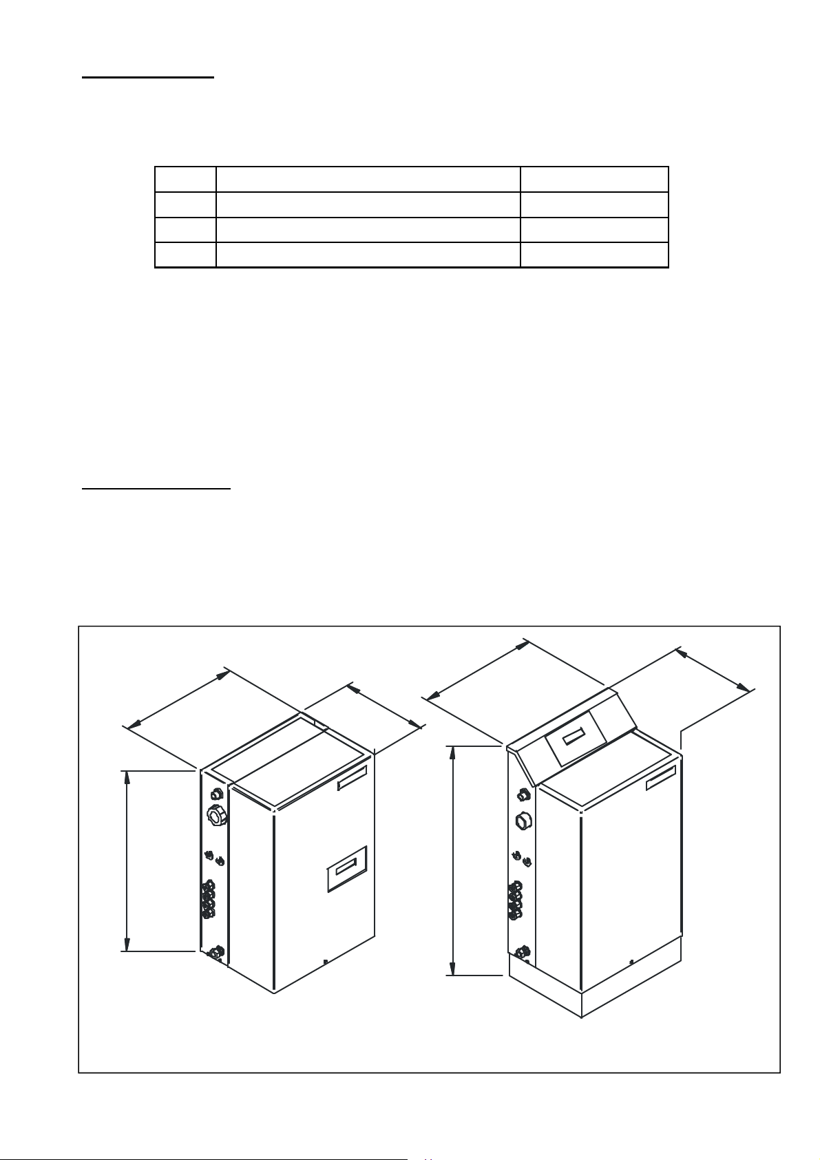
The basic overall dimensions of the unit are shown in Figure 2 below. Performance and General Data is shown in
Figure 3 (overleaf).
Model Description HHL Part Number
WSE Wall Mount / Single Pump / Electronic Control 563216016
FSE Floor Mount / Single Pump / Electronic Control 563216020
FTE Floor Mount / Twin Pump / Electronic Control 563216021
600
5
8
3
2
8
3
280
780
WALL MOUNTED WSE MODEL FLOOR STANDING FSE & FTE MODELS
280
Figure 2 - Basic Dimensions
HAMWORTHY HEATING LTD
1
CHESIL-ELECTRONIC
500001181/K
Page 7
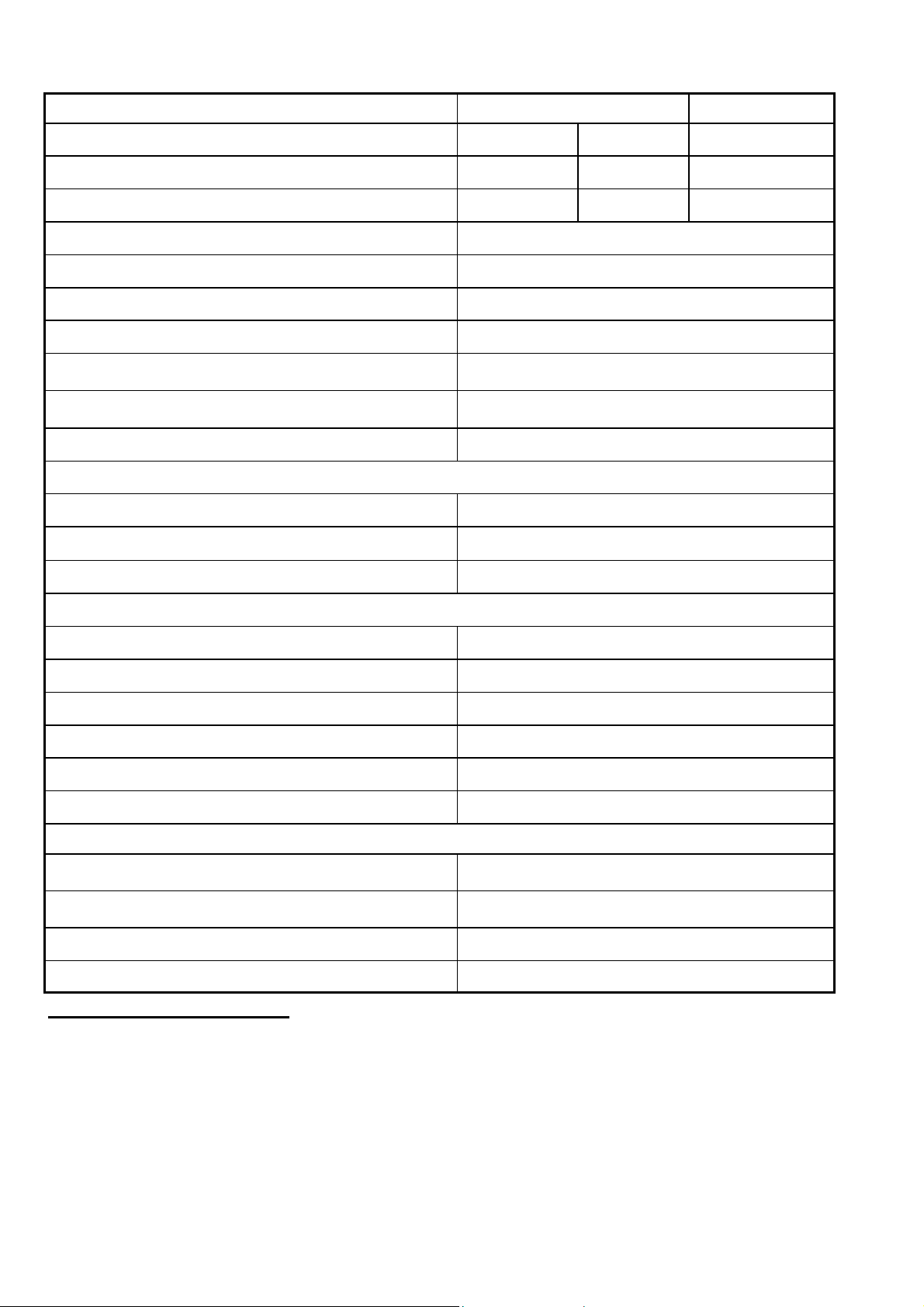
Figure 3 - Technical Data
Hamworthy Heating Part Number
Floor Standing Wall Mounted
563216020 563216021 563216016
Weight (empty) kg 23 29 21
Weight (full) kg 30.6 36.6 28.6
Tank capacity litres 7.6
Minimum cold fill pressure bar 0.5
Maximum cold fill pressure bar 3.4
Maximum operating pressure bar 7.0
Maximum Flow Rate l/min 6
Maximum water flow rate @
maximum cold fill pressure l/min
0.1
Backflow prevention air gap requirement Type AF
Factory Pre-set Values
Cold fill pressure bar 1.8
System low pressure alarm bar 1.3
System high pressure alarm bar 3.6
To suit system conditions
Maximum water flow temp °C 82
Maximum static height m 16.5
Minimum system operating pressure bar 0.7
Maximum system operating pressure bar 7.0
Safety relief valve setting (Not HHL supply) bar 4.0
Min. pressure differential bar 0.2
Electrical Data
Alarm Relay Contact Rating 13A 230V AC
Electrical Supply 230V AC 50Hz 1Ph
Start current amps 9
Run current amps 2.8
3.0 SEALED SYSTEM FUNCTION
Figure 4 shows the layout of a typical sealed system.
3.1 Terminology
Expansion Vessel Charge Pressure:
The gas pressure in the expan sion vessel with water connection open to atmosphere.
System Cold Fill Pressure:
The water pressure in the system that the pressurisation unit is set to maintain.
HAMWORTHY HEATING LTD
2
CHESIL-ELECTRONIC
500001181/K
Page 8
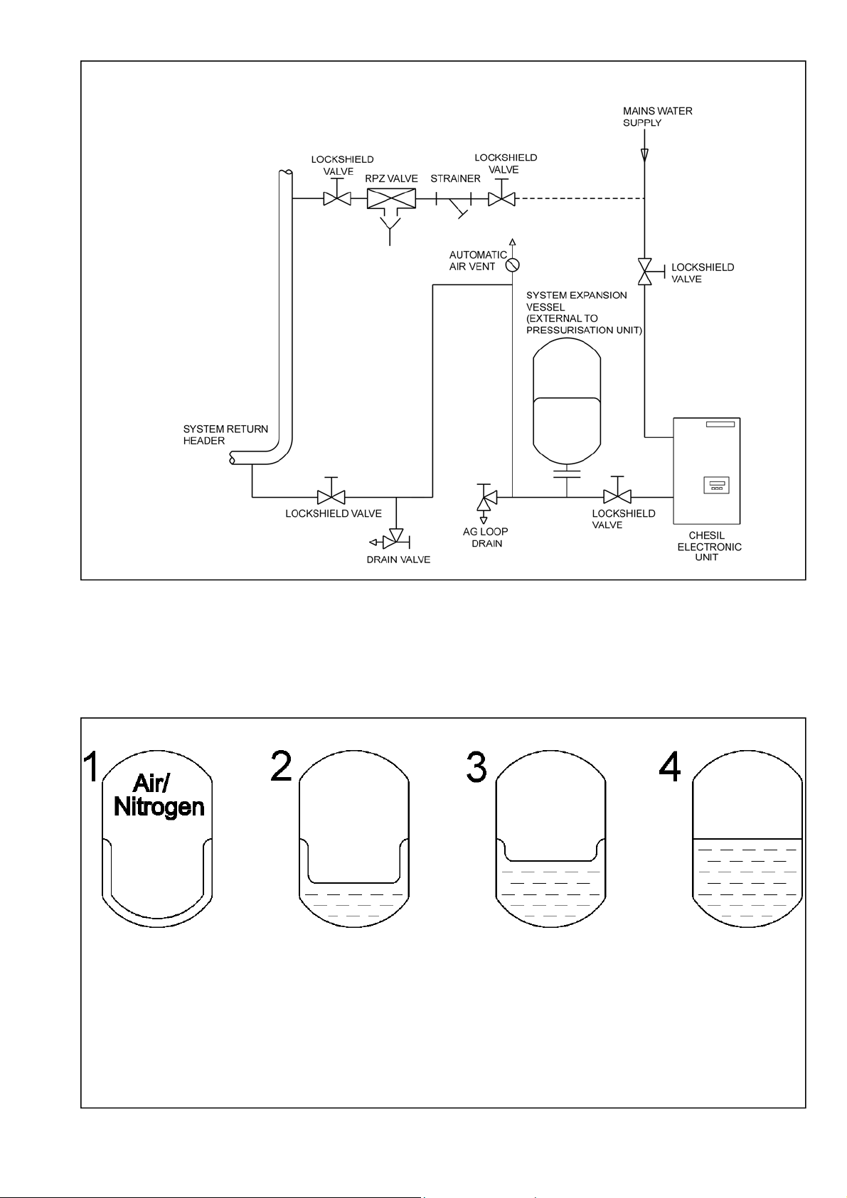
Figure 4 - Typical System Schematic Layout
3.2 Application
The system expansion vessel charge pressure is set 0.1 bar below the cold fill pressure. Before operation of the
boiler, with the system at cold fill pressure the expansion vessel is empty . As the system heats up the expanded
volume is absorbed by the expansion vessel. A small pressure rise occurs which is accommodated by the vessel.
When the system cools the pressure drops. If there has been some fluid loss the pressurisation provides
replacement.
Figure 5- Expansion Vessel Operation
1. Diaphragm position at the cold fill / charge pressure. The vessel is empty of system fluid.
2. Diaphragm position at the hot working pressure. The system volume has expanded due to the temperature
rise. The gas in the vessel is compressed. Acceptance factor = 0.35 maximum (recommended).
3. Diaphragm position at high system pressure. The boiler system is shut down by the system pressure
switch on.
4. Diaphragm at the safety valve lift pressure. Caused by boiler temperature limiter failure for example.
Acceptance factor = 0.5 maximum (recommended).
HAMWORTHY HEATING LTD
3
CHESIL-ELECTRONIC
500001181/K
Page 9
4.0 OPERATION OF THE PRESSURISATION UNIT
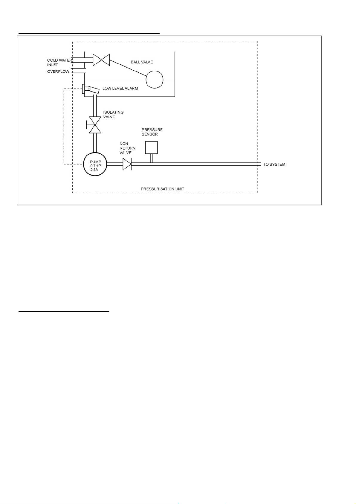
Figure 6 - Schematic Layout
4.1 Unit Operation.
The system pressure is continuously sensed by the pressure sensor in the pipe that connects to the heating
system. This is linked electrically to the PU electronic controller, which converts the signal from the sensor to a
pressure. The electronic controller checks this pressure against the user defined pressures to switch the
pressurisation pump on and off, and activate low or high pressure alarm relays if reached. The controller can also
determine the volume of water pumped into the system and compare this against user defined volumes to trigger
a general alarm relay. The controller also records the total run time of the pump(s) (if the unit is fitted with a backup pump), a user defined minimum run time can be set to stop the pump hunting when the on and off pressures
are close together. The user can predefine the electronics to alternate between pumps (in a twin pump unit) to
ensure that both pumps are operational. For small systems the user can select that the unit fills the heating
system from empty. For commercial systems Hamworthy Heating Ltd recommends that this ‘fill-function’ is only
used near the end of filling the system which should be filled with a suitable device such as an RPZ valve.
5.0 GENERAL REQUIREMENTS
5.1 Related Documents.
Pressure Systems and Transportable Gas Containers Regulations 1989.
It is the law that pressure system appliances are installed by competent persons in accordance with the above
regulations. Failure to install appliances correctly could lead to prosecution. It is in your own interest and that of
safety, to ensure that this law is complied with.
The installation of the pressurisation unit and expansion vessel MUST be in accordance with the relevant
requirements of the Pressure System Regulations, Building Regulations, IEE Regulations and the bylaws of the
local water undertaking.
It should also be in accordance with any requirements of the local authority and the relevant recommendations of
the following documents:-
Applicable standards and documents are:
BS 7074 Application, selection and installation of expansion vessels and ancillary equipment for sealed water systems.
BS 6644 Installation of Gas Fired Hot Water Boilers 60 kW to 2 MW
BS 6880 Parts 1,2&3: Code of practice for low temperature hot water heating systems of output greater than 45 kW.
BS 6759 Part 1 (ISO 4126): Specification for safety valves for steam and hot water.
BS EN 60335-1: Safety of household and similar electrical appliances
HAMWORTHY HEATING LTD
4
CHESIL-ELECTRONIC
500001181/K
Page 10
5.2 Mains Water Connections.
It is a requirement of the Water Supply (Water Fittings) Regulations 1999 that the system is filled using an RPZ
(Reduced Pressure Zone) valve with integral Type BA air gap. Information regarding the application, use and
maintenance requirements for RPZ valves with Type BA air gap is available from WRAS. It is also advisable to
contact the local water utility company to verify notification requirements for the use of these valves.
With the electronic model of Chesil pressurisation unit it is not always necessary to use an RPZ valve for system
filling as the units have a Fill function suitable for small systems to a maximum of 200 litres. Where this fill function
is used it is not necessary to have a quick fill loop using an RPZ valve.
5.3 Expansion Vessels.
System expansion vessels must be constructed to BS4814 or BS6144.
The required expansion vessel size is detailed in the contract documents. If in any doubt contact Hamworthy
Heating Limited for comprehensive system sizing information. Hamworthy Heating Ltd supply the ‘Burstock’ range
of suitable expansion vessels, details are shown below. A calculation sheet which can be used to determine a
suitable volume for an expansion vessel can be found in the Appendix.
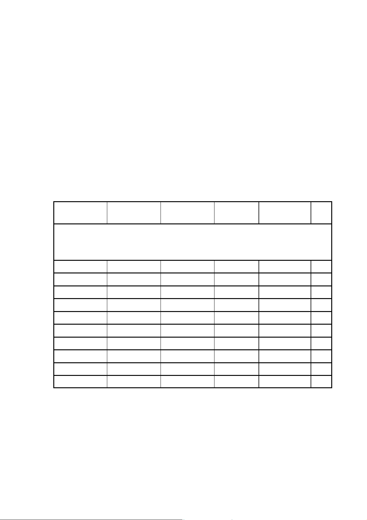
Figure 7 - Hamworthy Heating Expansion Vessels—’Burstock’
SALES REF NO.
HOT WATER
APPLICATIONS -
EPDM DIAPHRAGM
(0-100°C MAX)
HAMWORTHY PART
NO.
TYPE
TOTAL VOL.
LITRES
CONNECTION
DETAILS
WT
kgs
PV25W (kit) 563605641 VERTICAL 25 G3/4” 4.7
PV60W
PV80W
PV100W
PV200W
PV300W
PV400W
PV500W
PV800W
PV1000W
5327120094
5327120095
532712096
532712088
532712089
532712090
532712091
532712092
532712093
VERTICAL
VERTICAL
VERTICAL
VERTICAL
VERTICAL
VERTICAL
VERTICAL
VERTICAL
VERTICAL
60
80
100
200
300
400
500
800
1000
G1”
G1”
G1”
G1 1/4”
G1 1/4”
G1 1/4”
G1 1/4”
G1 1/2”
G1 1/2”
14
16
19
40
54
70
79
195
228
Note: 25 litre expansion vessels are supplied complete with wall mounting bracket
5.4 Safety Relief Valve.
Must comply with BS6759 part 1, and be sized and installed in accordance with BS6644 & BS7074.
HAMWORTHY HEATING LTD
5
CHESIL-ELECTRONIC
500001181/K
Page 11
6.0 INSTALLATION
W
The units are supplied inside strong cardboard boxes with paper padding and should be left in this packaging until
they arrive on site and are installed.
6.1 Location
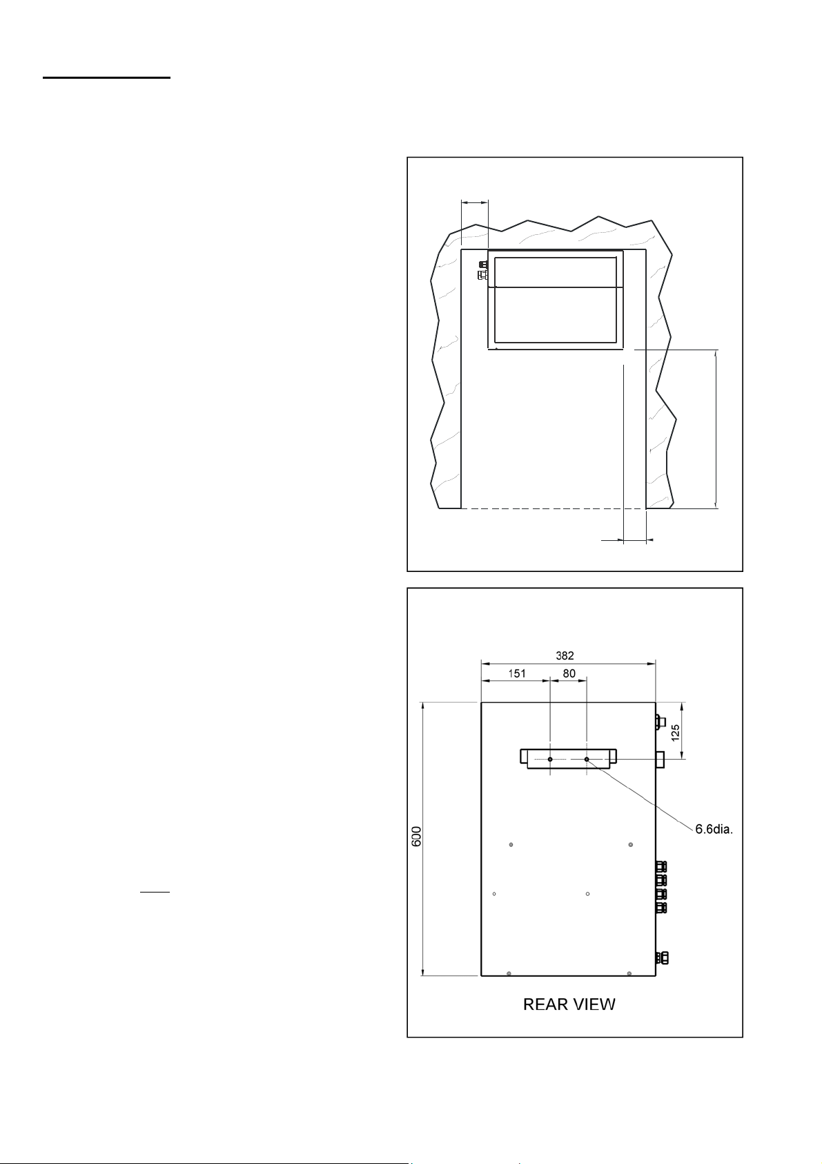
The units are designed for both wall mounting and floor
standing. A mounting bracket is supplied inside the unit
taped to the front of the tank for wall mounting. It is
intended that this bracket should be fixed to the wall and
the unit hung from it. Each unit also has two holes in the
back of the chassis for extra security. The
corresponding holes in the wall should be drilled to suit
once the unit is mounted on its bracket.
Floor standing models should be secured to the floor by
utilising the holes in the plinth.
The bracket dimensions are shown in fig 9 below.
Figure 8 - Recommended Clearances
100
450
150
PLAN VIE
6.2 Pipework Connections (Shown in Figure 10)
1) Mains water connection (½" BSP Male).
The units have a type ‘AF’ air gap to prevent backflow in
accordance with Water Supply (Water Fittings)
Regulations 1999. The water supply connection must
conform to all local WRAS regulations.
2) Plastic Overflow Connection (D32mm Bore Plastic
Waste Pipe).
Overflow should be piped to where it will be safe but
visible so it will be noticed and can be modified.
3) System connection.
The system connection is via a 15MM compression
fitting. The unit must be connected to the system by an
antigravity loop (see Figure 4). The antigravity loop
must be made in pipe-work no smaller than the
expansion vessel connection, and have a minimum
height of 2 metres. It should include a lock-shield (or
lockable) valve at the system connection point for
servicing and an automatic air vent fitted at the highest
point of the loop. The pipe-work and fittings must be
pressure tested to 1.5 times the safety valve lift
pressure.
Figure 9 - Wall Mounting Bracket Detail
HAMWORTHY HEATING LTD
6
CHESIL-ELECTRONIC
500001181/K
Page 12
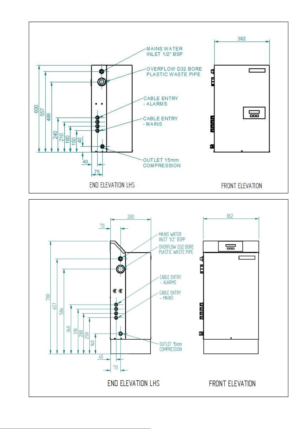
Figure 10 - Pipework Connections (Wall Mounted)
Figure 11 - Pipework Connections (Floor Standing)
HAMWORTHY HEATING LTD
7
CHESIL-ELECTRONIC
500001181/K
Page 13

6.3 Electrical connection
Wiring diagrams for the units can be found in
appendix A1. All wiring to the pressurisation unit
must be in accordance with the IEE regulations,
and any local regulations which apply. Note! If in
any doubt a qualified electrician should be
consulted.
6.3.1 Mains Connection
Units are supplied fitted with a 1m flying lead for
connection to the mains supply. Mains connection
must be via a fused isolator rated at 13 Amps and
positioned locally to the unit.
6.4 Electrical Connection To The User
Terminals (see Fig A1)
Terminals 1 to 3 are Low Pressure Alarm volt
free relay - 1 Normally Open, 2 Common and 3
Normally Closed. Suitable for up to 230V 0.5A
connection.
Terminals 4 to 6 are High Pressure Alarm volt free
relay - 4 Normally Open, 5 Common, 6 Normally
Closed. Suitable for up to 230V 0.5A connection.
Terminals 7 to 9 are General Alarm volt free relay
- 7 Normally Open, 8 Common 9 Normally Closed.
Suitable for up to 230V 0.5A connection.
Terminals 10 to 12 are for mains power coming
into power electronics - 10 Live (11 Earth) & 12
Neutral connection. Supply to be 230V single
phase 50Hz.
6.5 Operation of the Controller
Once wired, cover closed, and cable fitted to
pressure sensor, the unit is ready for operation.
When the mains supply is switched on the unit
becomes operational with factory settings applying.
After a few seconds the unit will become
operational and will start the pump(s) until pre-set
pressure has been achieved or until an alarm is
displayed (other than Low Pressure Alarm). Please
note, however, there is a fill function in the
Maintenance menu designed to bring the system
up to pre-set pressure which will ignore counters
such as volume of water introduced, pump cycle
count, hours run meter etc. See Maintenance
menu for more information.
Once system is in normal operation mode the word
‘AUTO’ appears, to indicate that the unit is in
working mode. The display will always revert to this
unless it is in alarm condition.
6.6 Trouble Shooting
In the event of the unit not coming on when mains
is applied, then please return the unit to HHL for
full investigation.
Once powered up, the unit will become operational.
Again, if the unit is not operating as you believe it
should, then please contact HHL Technical
Department for further assistance.
6.7 Standard Menu Display
By pressing the up and down keys you can scroll up
and down the standard menu in the order detailed
below. All items in menu are view only, except for
COLDFILLPRES which can be altered by user
between 0.7 Bar and 3.4 Bar in 0.1 Bar steps. By
altering the cold fill pressure, cut-in pressure and low
pressure alarm setting will move by same amount as
cold fill pressure is moved either up or down, unless
they hit their minimum. High pressure alarm setting
will move upwards once cold fill pressure is 0.2 Bar
below high pressure alarm, but will not move
downwards if cold fill pressure is brought down.
The structure of the standard menu is as follows and
can be scrolled through by using the up and down
keys:-
SYSTEM PRES X.X: This is current pressure reading
of system in Bar.
COLDFILLPRES X.X: This is the pump cut-out
pressure.
MAKE-UP V0 XXXX: This is volume of water
introduced into system in litres since the unit
was last reset.
MAKE-UP ALARM XX: This is alarm setting of
volume of water introduced since Make-up V2
was last reset in 10’s of litres (i.e. 23 would
mean 230 Litres).
MAKE-UP V2 XXX.X: This is volume of water
introduced into system in litres since make-up
V2 was last reset.
PUMP OPS XXXX: This is the total number of pump
cycles since pump ops was last reset.
PUMP1 HRS XX.XX: This is Pump 1 hours run since
Pump1 Hrs was last reset.
PUMP2 HRS XX.XX: This is Pump 2 hours run since
Pump 2 Hrs was last reset.
6.8 Maintenance Menu Display
This is obtained by pressing down the ‘up’ & ‘down’
arrows together for 5 seconds. The screen will
display either USER MENU ON or USER MENU OFF
depending on the previous menu setting.
Under Maintenance Menu you obtain access to
normal menu, plus added functions, with the facility to
make adjustments where appropriate. Structure of
HAMWORTHY HEATING LTD
8
CHESIL-ELECTRONIC
500001181/K
Page 14

menu is as follows and can be scrolled through by
using the up and down keys:-
SYSTEM PRES X.X: This is current pressure
reading of system in Bar. This item is nonadjustable - view only.
COLDFILLPRES X.X: This is the pump cut-out
pressure in Bar. This is settable from 0.7 to
3.4.
When moving coldfillpres, cut-in pres and
low pres alarm will move in line and will
always keep same differential (e.g. if
coldfillpres starts at 1.8, cut-in pres at 1.4
and low pres alarm at 1.2, and then
coldfillpres was moved to say 2.5, then cut in
pres would become 2.1 and low pres alarm
1.9), except when cut-in pres and low pres
alarm reach their minimum.
When moving coldfillpres upwards, high pres
alarm will also move upwards, but only once
0.2 Bar above the current setting (e.g. if
coldfillpres was moved to 3.1 then high pres
alarm will automatically become 3.3 if not
already higher). High pres alarm will not
move downwards when coldfillpres is moved
down.
MAKE-UP VO XXXX: This is volume of water
introduced into system in litres since the unit
was last reset.
This item is non-adjustable - view only.
MAKE-UP ALARM XX: This is alarm setting of
volume of water introduced since make-up
V2 was last reset in 10’s of litres (i.e. 23
would mean 230 Litres).
This is settable from 1 (10) to 99 (990).
This is used to set off General Alarm to warn
that the unit has introduced a certain amount
of water. For instance if set to 23, the alarm
will go off once the system has introduced
230 litres of water since make-up V2 was
last reset and the unit will be frozen and will
not resume its normal function until make-up
V2 is reset or make-up alarm is moved
higher than make-up V2 reading (divided by
10). Note: this function can be disabled by
setting the value to 00.
MAKE-UP V2 XXX.X: This is volume of water
introduced into system in litres since make-
up V2 was last reset.
By pressing the enter button this will be reset
to 000.0
PUMP OPS XXXX: This is the total number of
pump cycles since pump ops was last reset.
By pressing the enter button this will be reset
to 0000.
PUMP1 HRS XX.XX: This is Pump 1 hours run
since pump 1 hrs was last reset.
By pressing the enter button this will be reset to
00:00
PUMP2 HRS XX.XX: This is Pump 2 hours run since
pump 2 hrs was last reset.
By pressing the enter button this will be reset to
00:00.
CUT IN PRES X.X: This is Pump cut-in pressure in
Bar.
This is settable from 0.5 to 3.2.
Cut in pres automatically moves up and down
when coldfillpres is moved and will always
keep same differential it had before coldfill pres
was moved, except when cut in pres reaches
minimum.
However, cut in pres can be adjusted here. It
will only go upwards until 0.2 Bar below coldfill
pres setting. When moving the setting down,
low pres alarm will automatically move
downwards once 0.2 Bar below cut in pres.
L PRES ALARM X.X: This is Low Pressure Alarm
setting in Bar.
This is used to set off Low Pressure Alarm
Relay to warn that system is below desired
minimum pressure.
This is settable from 0.0 to 3.0.
Low pres alarm automatically moves up and
down when coldfill pres is moved and will
always keep same differential it had before
coldfill pres was moved, except when low pres
alarm reaches minimum. Low pres alarm will
also move down when 0.2 Bar below cut in
pres, when cut in pres is moved downwards
and will keep 0.2 Bar difference once this has
been reached.
However, low pres alarm can be adjusted here
but can never move higher than 0.2 Bar below
cut in pres setting.
H PRES ALARM X.X: This is High Pressure Alarm
setting in Bar.
This is used to set off High Pressure Alarm
Relay to warn that system is above desired
maximum pressure.
This is settable from 0.9 to 6.2.
High pres alarm will move up when 0.2 Bar
above coldfillpres, when coldfillpres is moved
upwards and will keep 0.2 Bar difference once
this has been reached. However, high pres
alarm can be adjusted here but can never
move lower than 0.2 Bar above coldfillpres
setting.
PUMP MIN RUN X.X: This is Pump Minimum run
time in seconds.
This is settable from 1.0 to 9.9.
This function can be used to stop hunting when
cut in pres and coldfillpres are very close
together.
PUMP MAX RUN X.X: This is Pump maximum run
HAMWORTHY HEATING LTD
9
CHESIL-ELECTRONIC
500001181/K
Page 15

time in minutes.
This is settable from 01 to 99.
PUMP DELAY XX: This is Pump minimum cycle
time in minutes.
This is settable from 00 to 99.
By entering a setting in here it will prevent
the pumps cycling until desired time has
elapsed.
PUMP KICK XX: This is Pump Duty cycle time in
days.
This is settable from 00 to 99.
This function will run the pump for 1 second
every XX days. This function is used to run
the pumps periodically.
PUMP : This is a Pump Selection function and is
displayed as XXXXX.
There are three settings: PUMP1. Will only call on pump 1 to operate
(cuts out Pump 2).
PUMP2. Will only call on pump 2 to operate
(cuts out Pump 1).
ALTERNATE. Will automatically cycle from
Pump to Pump taking into consideration the
pump delay setting. In the event of a Pump
failure, unit will keep on working with one
working pump when in ALTERNATE pumps
mode.
PASSCODE XX: This is Passcode function.
This is settable to ON or OFF.
When set to ON, any changes wishing to be
made to any setting will need the pass
number entered in.
PUMP TIMEOUT XX: This is pump failure setting
in minutes.
This is settable from 01 to 99.
This is used by electronics to determine
whether a pump has ‘failed’. The electronics
will monitor the pressure when the pumps
are on and if the pressure is not seen to rise
by 0.05 Bar during this pump timeout setting
then it will declare the pump as having failed.
This doesn’t actually mean the pump is not
working as there may be other reasons for
the pump not increasing the pressure, but
indicates that the unit/system should be
checked.
FILL FUNCTION: This is a Fill function and is
activated by pressing the enter key.
This function is used for final top up to bring
up system to required pressure whilst
disabling all counters (I.e. MAKE-UP V0,
MAKE-UP V2, PUMP OPS, PUMP1 HRS,
PUMP2 HRS will not be altered). The
system will bring up the system to cut out
pressure if reached within 6 hours and the
unit will then stop and FILL will flash on the
screen. To return the unit back to normal
operation the enter key needs to be pressed
again.
Once any required modifications have been made
under Maintenance Menu, it is advisable to revert
back to normal menu by holding the ’up’ & ’down’
arrows for 5 seconds until the screen displays USER
MENU OFF. No information is lost by doing this and
all last entered settings will remain. This will then
restrict amendments again to coldfill pressure setting
(see Standard Menu).
6.9 Alarms
There are a number of alarms and the unit will always
default to alarm display when one is in activation. The
unit will flash when in alarm mode to indicate that
there is a problem. If more than one alarm is tripped
then the system will display all alarms currently
affecting the unit - the unit will flash each alarm for a
couple of seconds before showing the next one, and
will continue to scroll through the list. When any
condition has been rectified the unit will continue to
display any other current alarms that still affect the
system. Only when all alarm faults have been
rectified, will the unit go back to Auto mode.
The alarms are as follows:ALARM-LO PRESS: This indicates that Low Pressure
Alarm has been breached. The unit will
continue to operate under this alarm function,
but invariably the alarm will be caused by
some other problem (e.g. too long a t3
setting).
ALARM-HI PRESS: This indicates that High Pressure
Alarm has been breached. The pump control
will be discontinued until the alarm fault has
been rectified.
ALARM-LEAK LIMIT: This indicates that Leakage
Volume Limit has been breached. The pump
control will be discontinued until the alarm
fault has been rectified. This can be done by
resetting Leakage Volume to 0, or by
increasing make-up alarm above make-up
V2.
ALARM-TANK LEVEL: This indicates that the water
level in the water tank is too low. The pump
control will be discontinued until the alarm
fault has been rectified.
Investigate reasons why water content of
tank is low.
FAULT PUMP1: This indicates that Pump 1 has
drawn over the allowed current and is
possibly at fault. You can press enter when
this displays, and the pump will come back
HAMWORTHY HEATING LTD
10
CHESIL-ELECTRONIC
500001181/K
Page 16

into service if it is working. It is worth
running Pump 1 to ascertain if it is faulty or
not.
FAULT PUMP2: This indicates that Pump 2 has
drawn over the allowed current and is
possibly at fault. Same remedy as for
FAULT PUMP1 alarm.
PUMP1 TIMED OUT This indicates that Pump 1
has not increased the pressure in the
system within the allowed time setting.
You can press enter when this displays,
and the pump will come back into service if
it is working. It is worth running Pump 1 to
ascertain if it is faulty or not. If this problem
persists and the pump is still working, then
pump timeout setting should be increased.
PUMP2 TIMED OUT: This indicates that Pump 2
has not increased the pressure in the
system within the allowed time. Same
remedy as for Pump 1 Timed Out alarm.
There are volt free relays on the unit to give
audible, visual or BMS signals that the unit has
gone into alarm mode. The Low and High Pressure
Alarms have their own circuits, with all other
conditions setting off General Alarm relay.
6.10 Factory Default Settings
The unit is supplied with the following default
settings.
COLDFILLPRES 1.8
MAKE-UP V0 0000
MAKE-UP ALARM 99
MAKE-UP V2 000.0
PUMP OPS 0000
PUMP1 HRS 00:00
PUMP2 HRS 00:00
CUT IN PRES 1.5
L PRES ALARM 1.3
H PRES ALARM 3.6
PUMP MIN RUN 1.0
PUMP MAX RUN 99
PUMP DELAY 00
PUMP KICK 30
PUMP SELECTOR ALTERNATE PUMPS
PASSCODE OFF
PUMP TIMEOUT 03
Technical Summary
Voltage Supply: 230V 1~ 50Hz Mains
Current rated at
690W
Maximum Working Voltage: 250V
Fuse Rating: 13A
Temperature Range: 4°C to 65°C
Housing Classification: IP65
HAMWORTHY HEATING LTD
11
CHESIL-ELECTRONIC
500001181/K
Page 17

7.0 COMMISSIONING
Chesil Electronic Units are supplied factory set and tested to suit the system parameters shown in Figure 3. If the
application falls within these parameters the unit requires minimal commissioning checks.
7.1 Mechanical Installation
Check that the Chesil Unit and expansion vessel has been installed correctly, as detailed in section 6.2: Pipe-work
connections.
7.2 System Flushing
Ensure that the system has been flushed and all foreign matter has been removed, including pipe scale.
Note! Should this material come into contact with the expansion vessel diaphragm it could result in premature
failure of the expansion vessel assembly.
7.3 Electrical Installation
Before working on Chesil units ensure the electrical supply & external circuits connected to the unit are isolated.
7.4 System Expansion Vessel (‘Burstock’ range)
To set or check the expansion vessel charge pressure the lock-shield valve between the Chesil unit and the
vessel must be closed. The drain cock fitted on the base of the expansion vessel must be open to allow any water
in the vessel to escape.
A suitable gauge should be used to check the charge pressure. Generally a Schrader ‘car type’ valve is fitted near
the top of the expansion vessel. If the charge pressure is too high it can be reduced by depressing the centre of
the Schrader valve or by using a pressure gauge with an integral air release valve. If the charge pressure is too
low a small increase can be provided using a car foot pump otherwise an oil free compressor or nitrogen bottle is
recommended.
Note! The expansion vessel charge pressure should be set to 0.1 bar less than the cold fill pressure.
When the correct pressure is set the Schrader valve protective cap must be replaced.
Check the integrity of the pipe-work. Ensure the lock-shield valve between the Chesil unit and the expansion
vessel is open and the drain valve is closed. Ensure the air purge plug is fitted (near the top of the expansion
vessel).
HAMWORTHY HEATING LTD
12
CHESIL-ELECTRONIC
500001181/K
Page 18
7.5 Initial Setting of Unit
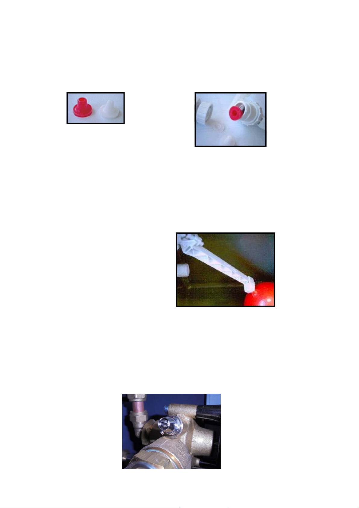
Each unit comes with a selection of inserts that can be fitted into the inlet valve to achieve the required output:
Mains inlet pressure > 4 bar H.P. restrictor (white see fig 12)
Mains inlet pressure < 4 bar L.P. restrictor (red see fig 12)
The HP restrictor is fitted in the inlet side of the float valve assembly. This
should be unscrewed in order to change the restrictor (see fig 13). The LP
Restrictor is clipped to the side of the valve assembly.
Figure 12 - Restrictor Inserts
Figure 13 - Changing Restrictor Inserts
3) If the cold water is from a tank then the tank must be at least 2m above the inlet for the header tank to remain
full when the pump is working at maximum rate. The pressurisation units should not be used to fill a heating
system.
4) Check that the unit has been connected to the system using a suitable isolation valve.
5) Check that the mains lead has been connected to a suitably fused and switched isolator.
6) The cold fill pressure on the units are factory set to the levels listed in figure 3 as are the Hi & Lo pressure
alarms. If these levels are unsuitable for the installation then adjustment will be necessary.
7) Set the float to its lowest level. (fig 14)
7.6 Filling The Unit
Figure 14 - Float Adjustment
1) Check all connections and pressures. Remove front cover by unscrewing securing screw at base of unit and
lifting cover up and slide forwards.
2) Undo the priming screw on pump head (fig 15). Prime until air stops escaping. Close the screw & turn on the
supply to the unit (keeping system isolation valve closed). Pump will run for a few seconds until set pressure is
reached.
3) Check for any leaks within the unit, if OK open system isolation valve.
4) The unit will now monitor the system and keep it at the required pressure.
HAMWORTHY HEATING LTD
Figure 15 - Priming Screw
13
CHESIL-ELECTRONIC
500001181/K
Page 19

7.6.1 User Defined Pressure Levels
Any adjustments required away from the standard factory set operating parameters can be made
following the instructions detailed in the maintenance section 6.8.
7.7 Pump Spindle Access hole
A Ø20mm hole has been added to the right hand side panel of the back plate to allow for screw driver access
to the pump drive spindle. This hole may be utilised following the removal of a rubber bung.
HAMWORTHY HEATING LTD
14
CHESIL-ELECTRONIC
500001181/K
Page 20

8.0 FAULT FINDING
General fault finding is shown in Figure 17. If the Chesil unit still does not operate satisfactorily, consult
Hamworthy Heating for assistance.
Figure 17. Fault Finding Guide.
Fault Possible Causes Action
Pump will not run Unit up to pressure
No power to the unit
Isolator fuse blown
Cut In Pressure set incorrectly
Pump seized or faulty
Pump runs but will not build
up pressure
Pump isolating valve closed
Pump not primed
Float switch faulty
Pump non return valve jammed
Blocked flow restrictor
Pump cuts in and out
rapidly (hunting)
Value of cut in & coldfill pressure
set incorrectly
Non return valve not sealing
correctly
System Leak
Pump runs continuously Value of coldfill pressure set
incorrectly
Pump relay faulty
System leak
Pump cuts out at wrong
pressure
Pressure gauge being compared
with is inaccurate.
Internal pressure sensor faulty.
Maximum system working
pressure too high
Coldfill pressure set incorrectly
Internal pressure sensor faulty.
Boiler switches off un-
expectedly
Hi or lo pressure alarms set
incorrectly
Safety circuit is wired incorrectly
System pressure runs
Small system leak Trace leak and ensure system is sound
consistently at cold fill
pressure
None
Check at source
Replace fuse in isolator. Note! Investigate cause of
blown fuse before restarting the unit
Adjust cut in pressure (see section 6.8)
Service or replace pump (see section 10)
Open valve
Prime pump (see section 7.6)
Check water level and replace float switch.
Check valve
Check flow restrictor for blockage
Adjust values
Clean valve seat or replace valve if necessary (see
section 10.4)
Trace leak and ensure system is sound
Adjust value
Replace faulty relay PCB in grey box (see section
10.5)
Trace leak and ensure system is sound
Replace pressure gauge.
Replace pressure sensor (see section 10.6)
Adjust value
Replace pressure sensor (see section 10.6)
Adjust values
Check wiring with Wiring diagram in appendix
HAMWORTHY HEATING LTD
15
CHESIL-ELECTRONIC
500001181/K
Page 21

9.0 SERVICING SCHEDULE
The following is a recommended servicing schedule for the Chesil unit and expansion vessel. If remedial action is
required, refer to section 10: SERVICING AND REPLACEMENT OF COMPONENTS. If in doubt consult
Hamworthy Heating.
9.1 6 Monthly
1) Check the expansion vessel charge pressure, as described in section 7.4. A significant drop in charge
pressure could be due to a faulty vessel diaphragm; replacement of diaphragm should be considered. See
section 10.9.
2) Check the value for PUMP KICK. Adjust if necessary then briefly reduce the system pressure to check for rotor
seizure. This could occur if the pump is not run for extended periods. This can be accomplished by slightly
opening the expansion vessel drain valve to initiate a leak.
Note! Ensure that the drain valve is closed after this operation.
9.2 12 Monthly
1) Check the ball float valve diaphragm seat for integrity and replace if necessary. Also check the plastic float for
soundness.
2) Check the expansion vessel for signs of external corrosion. If any deterioration is observed then it is
recommended that the frequency of inspection be increased.
3) Check the operation of the safety circuits if utilised.
4) Check the V2 setting and reset if this is close to the maximum limit.
Note: a high reading accumulated over a short period of time could indicate a system leak and should be
investigated.
9.3 4 Yearly
1) Remove the expansion vessel diaphragm as described in section 10.9 and insp ect for wear/ageing.
Inspect the internal surface of the vessel for corrosion.
Significant corrosion can lead to failure of the vessel; replacement of the entire vessel should be considered.
If necessary replace the diaphragm as described in section 10.9.
HAMWORTHY HEATING LTD
16
CHESIL-ELECTRONIC
500001181/K
Page 22
10.0 SERVICING AND REPLACEMENT OF COMPONENTS
Note! When servicing or replacing components electrically isolate the unit and close the system and expansion
vessel isolating valves. The unit should also be isolated from the pressure alarm circuits.
When remaking screwed connections use a thread sealant.
The cover on the unit is secured by one screw at the lower edge of the front panel only.
10.1 Hamworthy Heating Recommended Spares
Part Part N°
Pump Assembly (Single Pump Unit) 530905053
Pump Assembly (Twin Pump Unit) 530905054
Pressure Sensor 532496005
Control Box Assembly (Wall Mount Unit) 533901788
Main Control PCB Single Pump Unit 533901784
Main Control PCB Twin Pump (Floor Standing Unit) 533901785
LCD Display PCB 533901786
Float Switch 531203006
Float Valve Assembly 531911038
Non-return valve cartridge 531911040
NOTE! For any service/replacement parts the unit serial No. (on the Data Plate inside the unit) MUST be
quoted. For service or spares contacts please refer to the inside front cover of this guide.
10.2 Pump Removal (part n° 530905053 & 530905054 )
1) Isolate unit from electrical & water supplies as well as connecting circuitry.
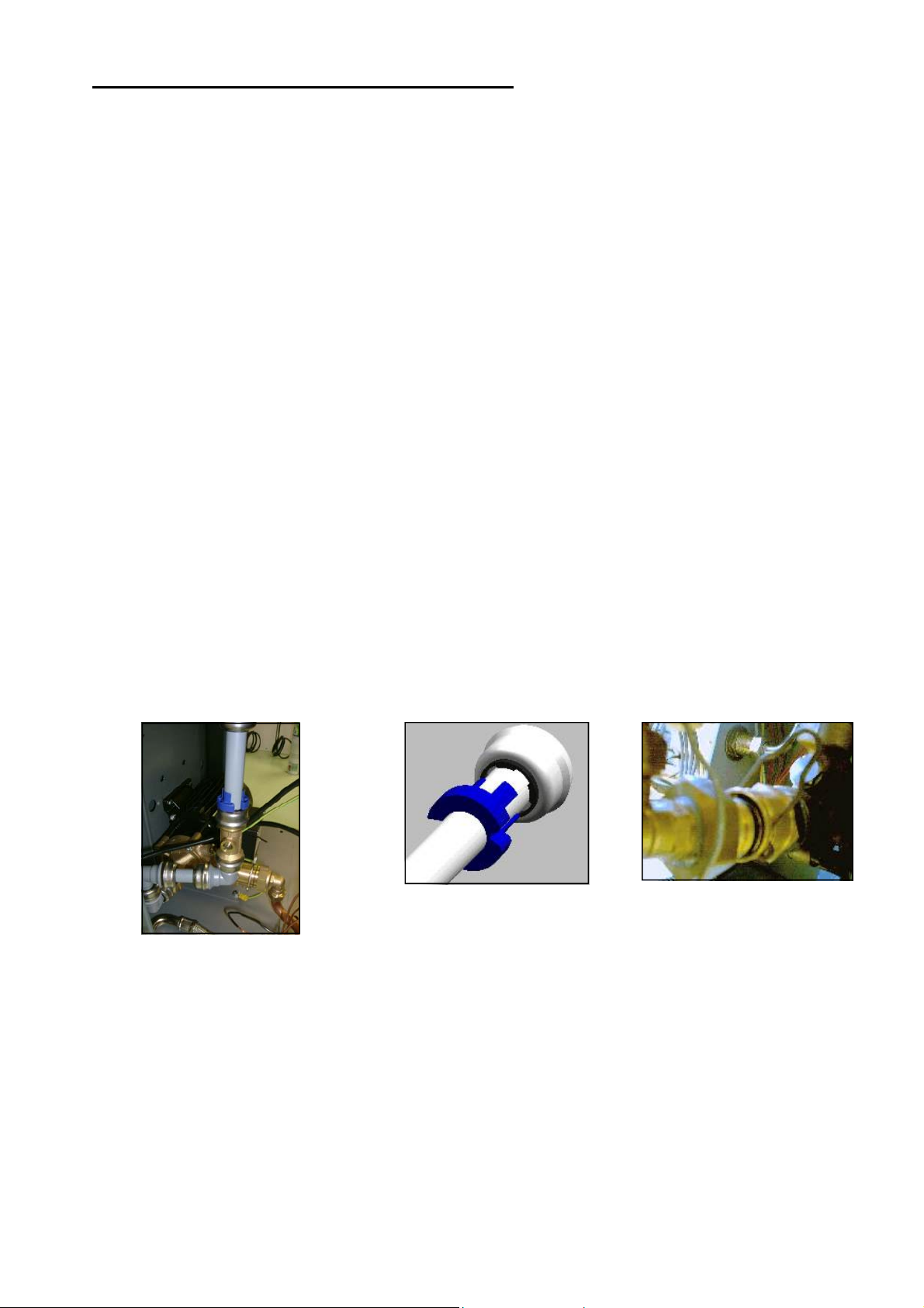
2) Isolate water by turning screw in ball valve see fig 18 below.
2) Disconnect the tube from the last grey elbow fitting using the blue tool provided. Take care to line up the
tool correctly before pushing the tool into the fitting to release the pipe (see fig 19).
3) Disconnect the outlet pipe from the pump. Remove the quick release clip first (see fig 20).
4) Disconnect the wiring on the mains terminal (see fig A1).
5) The pump assembly including the mounting plate can now be removed from the unit.
6) When the pump assembly has been removed the pump can then be removed from the assembly.
Figure 19 Figure 20
Figure 18
10.2.1 Pump Fitting
Pump fitting for each unit is basically the reverse of pump removal.
Care should be taken not to over tighten the 2 pump mounting screws as this can shear the welded thread. Once
re-fitted and connected the pump needs to be bled. Instructions of this can be found in section 7.6.
HAMWORTHY HEATING LTD
17
CHESIL-ELECTRONIC
500001181/K
Page 23
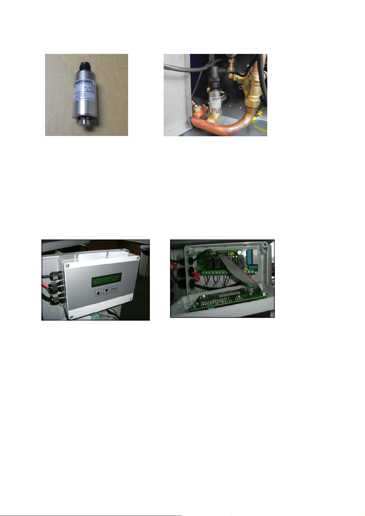
10.3 Replacement Of Pressure Sensor (Part No.532496005)
The pressure sensor is assembled into the outlet pipe work from the pump.
Figure 22 - Location Of Sensor Figure 21 - Pressure Sensor
1) Isolate the unit from the electrical, water supply & connecting circuitry.
2) Unscrew the Black cable socket from the sensor and pull backwards to disconnect (Fig 21).
3) Unscrew the sensor from it’s soldered boss. (Fig 22)
4) Apply a small amount of WRAS approved sealant to the thread of the replacement sensor.
5) Screw the replacement sensor into the boss.
10.4 Replacement Of Control Box Assembly On Wall Mount Unit (Part No. 533901788)
To remove the control box assembled to the door of the unit.
Figure 23 - Control Box Figure 24 - Controller Terminals
1) Ensure the unit has been isolated from the 230V / 50Hz mains supply & connecting circuitry.
2) Unscrew the screw at the base of the sheet metal front cover of the unit and lift off the cover from the unit.
3) Unscrew the 4 screws shown in figure 23 and remove the lid of the box.
4) Disconnect the terminal connections to the PCB.
5) Loosen the cable gland nuts of the box and withdraw the terminal ends of the cables through the glands.
6) Remove the M3 nuts behind the hinged door panel to unfix the control box to the door.
7) Replace the control box and secure to the door using the nuts.
8) Open the replacement box by removing the lid.
9) Loosen the cable gland nuts of the replacement box and feed the ends of the cables through the glands
and connect the cables to the correct terminal of the PCB. Refer to the wiring diagram in Appendix A1.
10) Reassemble the lid of the box , reconnect the electrical supply to the unit and replace the sheet metal front
cover on the unit.
HAMWORTHY HEATING LTD
18
CHESIL-ELECTRONIC
500001181/K
Page 24
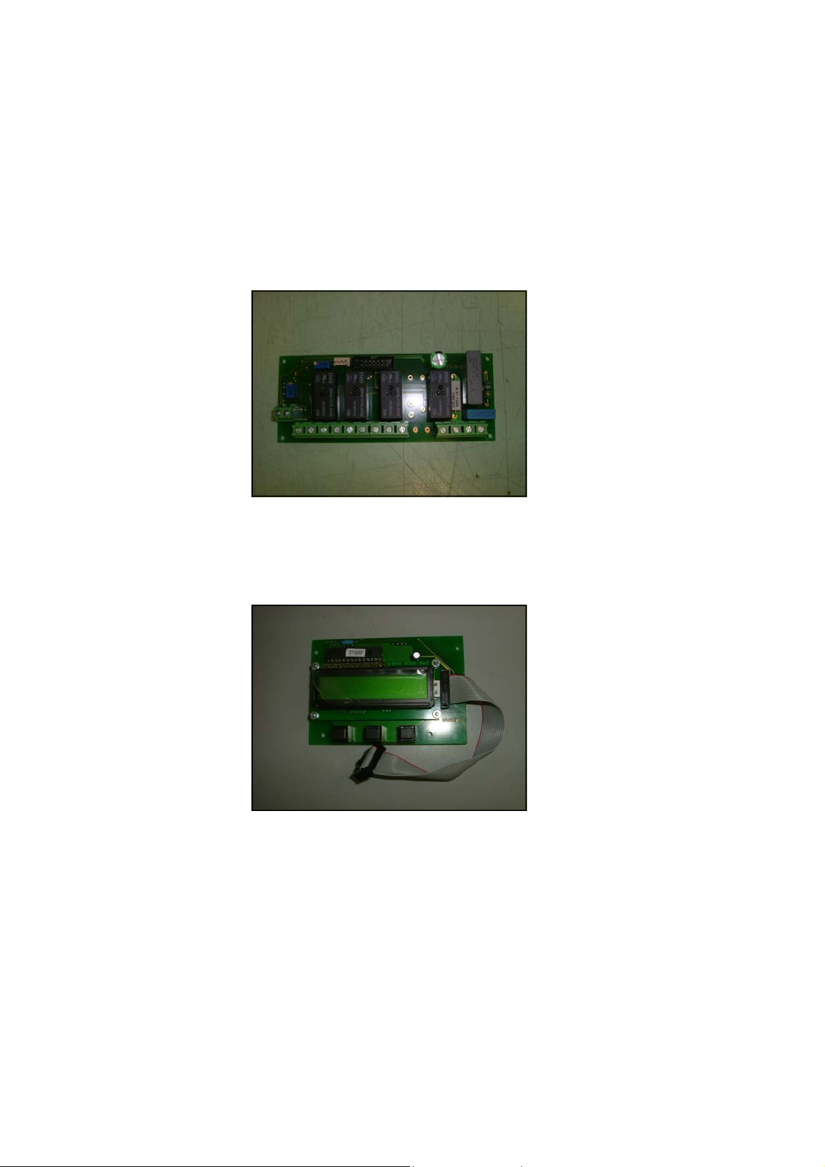
10.5 Replacement Of Controls PCB (Part No 533901784 - Single pump PCB / 533901785 - Twin Pump
PCB)
The main control PCB of the wall mount and floor standing units are enclosed in a plastic box at the same position
on the hinged door of the unit. To replace the mains PCB :-
1) Ensure the unit has been isolated from the 230V / 50Hz mains supply & connecting circuitry.
2) Remove the front cover of the unit Remove the lid of the box.
3) Disconnect the wires to the terminals of the PCB.
4) Loosen the nuts securing the PCB to the stand offs in the box.
5) Locate the replacement PCB over the stand-offs and secure the PCB to the stand-offs by reassembling the
nuts.
6) Reconnect the wires to the correct terminal of the PCB as defined in the wiring schematic of Appendix A1.
7) Reassemble the lid of the box and reconnect the power to the unit.
Figure 25 - Main Control PCB (Single Pump Unit)
10.6 Replacement Of Display PCB (Part No. 533901786) on Wall Mount Unit.
Figure 26 - Display PCB
1) Isolate the mains electrical supply.
2) Remove the sheet metal front cover as previously described.
3) Remove the lid of the plastic box.
4) Remove the ribbon cable plug of the from the main PCB.
5) Remove the earth lead connection.
6) Remove the nuts securing the display PCB to the stand-offs in the lid of the box.
7) Replace the display PCB to the stand offs in the lid and secure using the nuts.
8) Replace the earth lead connection.
9) Reconnect the new display PCB ribbon cable plug to the main PCB and reassemble the lid.
10) Replace and secure the sheet metal front cover & reconnect the electrical supply.
HAMWORTHY HEATING LTD
19
CHESIL-ELECTRONIC
500001181/K
Page 25
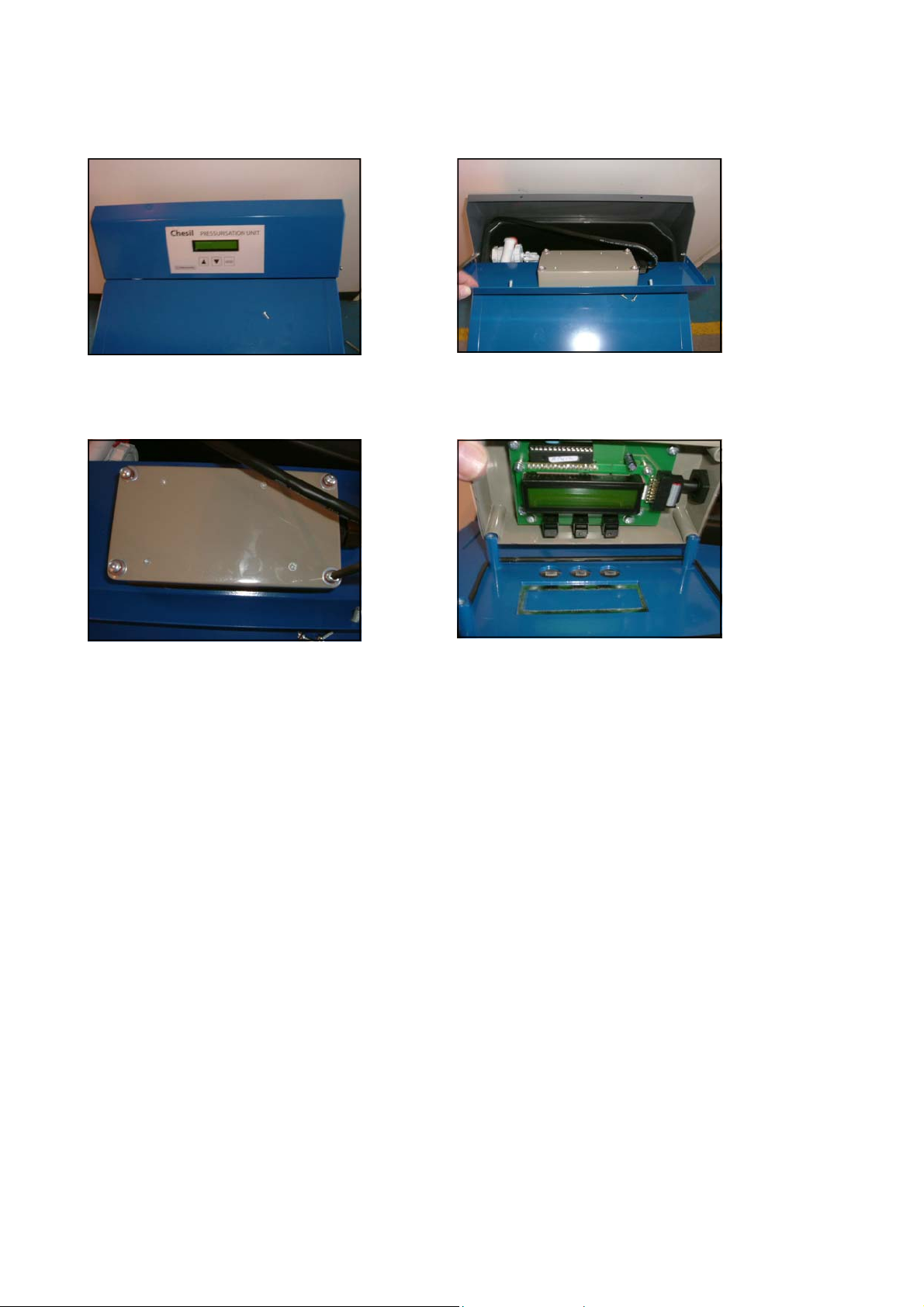
10.7 Replacement Of display PCB (Part No. 533901786) on Floor Mount Unit
The display PCB is assembled to the rear side of the inclined panel of the Floor mounted unit see Figure 27.
Floor Standing Unit
Figure 28 - Removal Of Inclined Panel Figure 27 - Display PCB Location
Figure 29 - Enclosure Disassembly
Figure 30 - Assembly Of Display PCB In Enclosure
To replace :-
1) Isolate the unit from the mains electrical supply.
2) Remove securing screws found either side of the inclined top panel.
3) Lift panel off and lay flat on top of the sheet metal front cover.
4) Loosen screws securing the plastic box enclosing the display PCB to the inclined sheet metal panel.
5) Disconnect ribbon cable plug from Display PCB.
6) Remove the earth lead connection.
7) Unfasten screws securing the display PCB on the stand off’s in the plastic box.
8) Remove the display PCB from the stand offs and replace the PCB.
9) Reassemble everything in reverse order making sure the seal is in place on the enclosure & reconnect the
mains electrical supply to the unit.
10.8 Replacement Of Low Water Level Switch (Part No. 531203006)
The tank contains a water level switch for general alarm indication.
1) Isolate the unit from the mains water & electrical supplies.
2) Remove the screw securing the front cover and remove front cover.
3) Remove the lid from the main control box & disconnect terminals 1 & 2 on the control PCB.
4) Loosen the nut off the cable gland through which the cable of the level switch is fed to the control box.
5) Withdraw the terminalised end of the level switch cable through the cable gland and heat shrink tube.
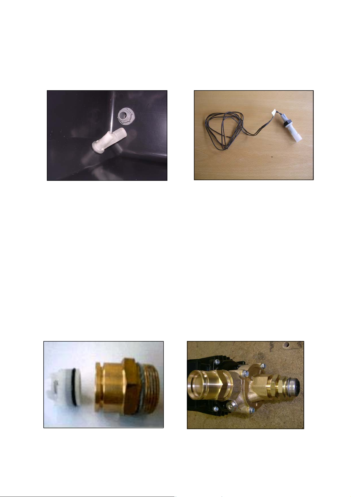
6) Drain the supply tank of water. Refer to Figure 31.
7) Undo the nut on the outside of the tank securing the float switch to the tank and remove the defect float
switch. Refer to Figure 32.
8) Replace the level switch and secure the bulkhead nut, ensuring the seal on the inside of the tank is correctly located and the float is operating correctly.
HAMWORTHY HEATING LTD
CHESIL-ELECTRONIC
20
500001181/K
Page 26
9) Feed the end of the level switch wire back through the heat shrink tubing, through the cable gland (& nut) &
into the control box.
10) Reconnect the end of these wires to terminals 1& 2 of the main control board.
11) Tighten the cable gland nut and put the control box lid back on.
12) Reconnect the electrical supply to the unit. The unit should go into General Alarm mode.
13) Reconnect the mains water supply which should lift this alarm.
14) Lift the front cover back on & secure with screw.
Figure 31 - Level Switch In Tank
Figure 32 - Level Switch As Supplied
10.9 Inlet Valve (Part N° 531911038)
The inlet valve and float in the header tank are supplied as one assembly (see fig 14).
1) Isolate the unit from the water supply.
2) Undo 1/2”BSP connection to remove supply pipe.
3) Unscrew the lock nut from the inlet tube. The valve and float are now free to be removed.
4) On the standard unit there is a black spacer which fits between the tank and the chassis. This must be
refitted when a new assembly is installed.
5) Once fitted the float adjustment should be set to the lowest level (see section 7.5).
10.10 Non-Return Valve (Part N° 531911040)
1) Follow the procedure for removal of the pump (see section 10.2).
The valve is inside the brass quick release fitting shown in figure 34.
2) Unscrew the brass fitting from pump.
3) Push the valve out from the brass fitting (see fig 33).
Figure 33 - Non Return Valve Assembly
Figure 34 - Non Return Valve Fitting
Location On Pump
HAMWORTHY HEATING LTD
21
CHESIL-ELECTRONIC
500001181/K
Page 27
11.0 Frost Protection Kit (Optional Extra)
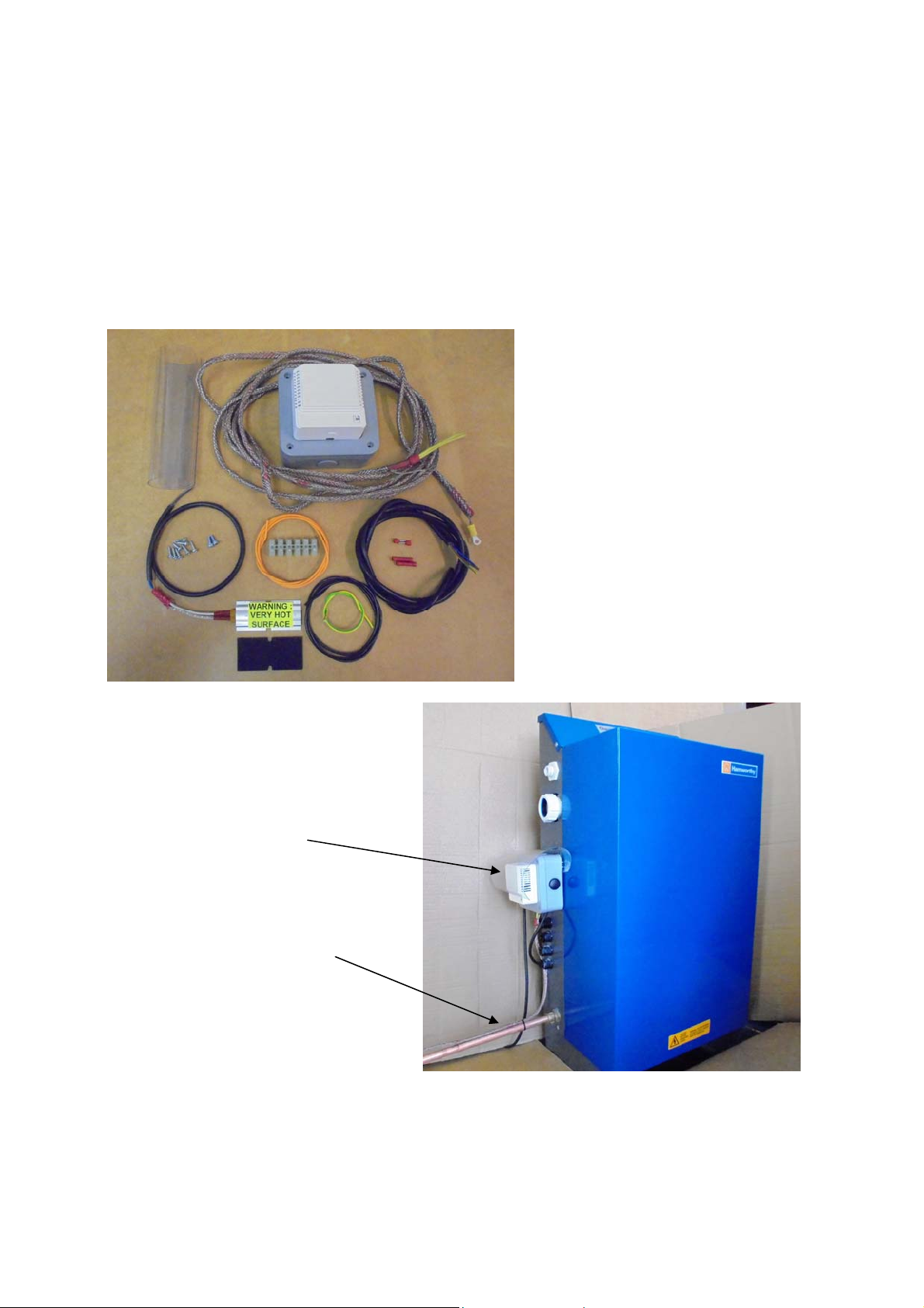
This is an optional extra kit available from Hamworthy Heating Ltd - Part No. 563605663
The Frost Protection kit consists of a small heating element, a thermostat, 5M of trace cable and all wiring
required to retro-fit the frost protection kit to any Chesil Electronic pressurisation unit.
Installation instructions are supplied separately with the kit.
Useful for installations where the Chesil unit could be subjected to ambient temperatures approaching 0°C.
At a set temperature, determined by the thermostat supplied, a small heating element affixed to the baseplate of
the unit will be activated raising the ambient temperature within the Chesil casing. At the same time the 5M of
trace cable, attached to the PU water supply pipe, will help to prevent the water from freezing.
Please contact Hamworthy Heating Ltd for further information.
Figure 35 - Frost Protection Kit (optional)
Figure 36 - Frost Protection Kit - Installed
Thermostat
Trace cable (attached to the units
water supply pipe)
Spares for Optional Frost Protection Kit:
Heater…………... ………………………………………………………………………………………… ……….533901789
Thermostat………………………………………………………………………………………………………….533901790
Trace Cable (5M)…………………………………………………………………………………… ……………..533901791
HAMWORTHY HEATING LTD
22
CHESIL-ELECTRONIC
500001181/K
Page 28
Contents Page
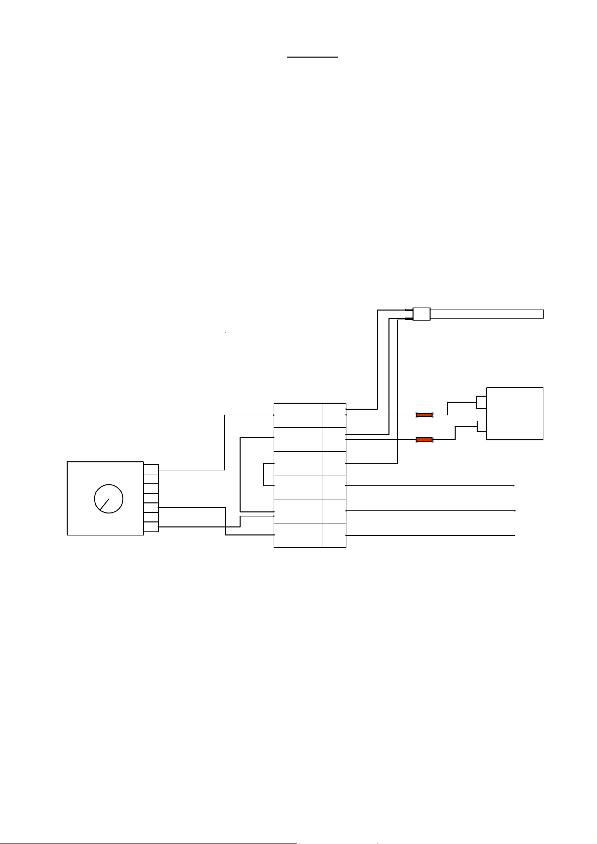
Figure A1 Frost Protection Kit Wiring Diagram 23
Figure A2 Main Wiring Diagram 24
Figure A3 Heating System Calculation Sheet 25
APPENDIX
YELLOW
YELLOW
EARTH wir e
attached with
trace cable
TRACE CABLE
ORANGE
GREEN/
THERMOSTAT
1
2
3
4
YELLOW
BLACK
BLACK
ORANGE
Figure A1 - Frost Protection Kit Wiring Diagram
1
2
3
BROWN
BLUE
EARTH
CONNECTOR
CONNECTOR
4
5
6
WHITE
WHITE
GREEN/YELLOW
PANEL
HEATER
BLUE
BROWN
HAMWORTHY HEATING LTD
23
CHESIL-ELECTRONIC
500001181/K
Page 29
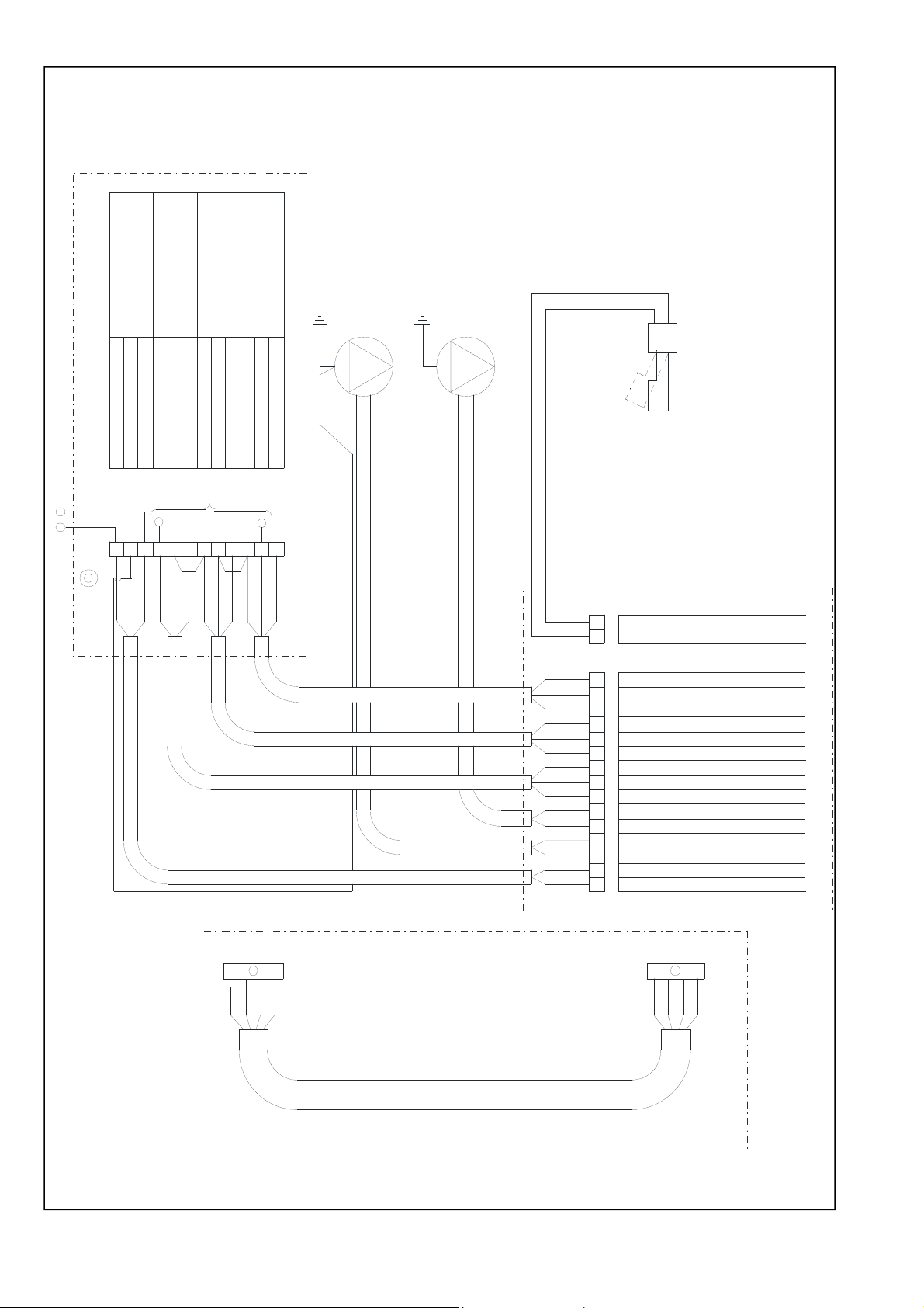
Figure A2. Wiring Diagram
MAINS SUPPLY
240V/50Hz
10AMPS
NEUTRAL
EARTH
GENERAL FAULT
(MAX. 240V 0.5a)
ALARM, VOLT FREE
LIVE
NORM ALLY CLOSED
COMMON
HIGH PRESSURE
ALARM, VOLT FREE
(MAX. 240V 0.5a)
NORM ALLY OPEN
NORM ALLY CLOSED
COMMON
NORM ALLY OPEN
LOW PRESSURE
ALARM, VOLT FREE
(MAX 240v 0.5a)
TANK LEVEL SWITCH
NORM ALLY CLOSED
COMMON
NORM ALLY OPEN
USER TERMINALS
G/Y
PUMP 1
G/Y
PUMP 2
240V/50Hz
12
Blue
10
11
G/Y
Brown
SAFETY CIRCUIT
6
7
8
9
Black
Brown
Black
Grey
Black
1
2
3
4
5
Grey
Brown
Black
Brown
Grey
Grey
Grey
Grey
Black
Grey
Black
12
Black
Grey
Black
Brown
Black
Grey
Brown
Grey
Black
Brown
Blue
Brown
Brown
Blue
Blue
Brown
WATER LEVEL SWITCH
3 4 5 6 7 8 9 1011121314151617
LOW ALARM NO (PU POWERED)
LOW ALARM NC (PU POWERED)
LOW ALARM COMMON
HIGH ALARM NC (PU POWERED)
HIGH ALARM NO (PU POW ERED)
HIGH ALARM COMMON
GENERAL ALARM NO (PU POW ERED)
GENERAL ALARM NC (PU POWERED)
GENERAL ALARM COMMON
PUMP 2 NEUTRAL
PUMP 2 LIVE
PUMP 1 LIVE
PUMP 1 NEUTRAL
MAINS NEUTRAL
MAINS LIVE
MAIN CO NTROLLER PCB
4
Gr een not connec ted
Green
Blue
HAMWORTHY HEATING LTD
SE NSOR CONNECTOR
2
1
Red
Yellow
Black
24
CHESIL-ELECTRONIC
BOX CONNECTOR
Yellow
Blue
PRESSURE TRANSPONDER CABLE
Green
Red
500001181/K
Page 30
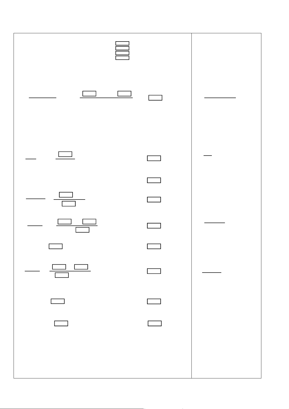
Figure A3 - Heating System Calculation Sheet
1. System Parameters
System Water Content - Vs = litres
System Anti-freeze Content - ra = %
Maximum System Working Pressure - P
Maximum Static Head -
= bar
w
Ph = metres
If the system volume is not known then the following rule of thumb can be applied:
System water content = Boiler power (KW) X 10
2. Expansion Vessel Volume Calculation, Vv-
(ra + 81.5) x Vs ( + 81.5 ) x
Vv = = Vv = litres
921 921
If the system is to be set up using the factory preset alarm levels for the Chesil unit then no other
calculations are necessary. The factory preset levels are:
Hi Pressure Alarm Level, P
Lo Pressure Alarm Level, P
The safety valve lift pressure should be set 0.35 bar above the Hi pressure alarm level.
Cold Fill Pressure Switching Level, Pf = 1.8 bar
= 3.6 bar
hi
= 1.3 bar
lo
3. Cold Fill Pressure Switch Setting Calculation, P
-
f
P
P
h
= + 0.2 = + 0.2 Pf = bar
f
10.2 10.2
4. Safety Valve Lift Pressure Calculation, P
-
s
Actual fitted expansion vessel volume, V
- V
va
Actual fitted expansion vessel acceptance factor, a
-
va
va =
litres
V
a
V
x 0.35 x 0.35
v
= = ava =
va
va
Actual working pressure, P
-
wa
P
P
1 - a
+ a
f
= = P
wa
va
1 -
va
+
= bar
wa
Note! If P
Ps = Pwa + 0.7 = + 0.7 Ps = bar
> Pw then increase expansion vessel volume, V
wa
and recalculate from step start of step 3
va
5. Calculation of Expansion Vessel Acceptance Factor at Safety Valve Lift Pressure, as-
P
a
P
- Pf -
s
= = as =
s
+ 1 + 1
s
Note! If as > 0.5 then increase expansion vessel volume, V
6. Lo Pressure Alarm Setting Calculation, P
and recalculate from step start of step 3
va
-
sl
= Pf - 0.3 = - 0.3 Psl = bar
P
sl
7. Hi Pressure Alarm Setting Calculation, P
si -
= P
P
- 0.35 = - 0.35 Psh = bar
sh
wa
Example
Vs = 2000 litres
ra = 10%
= 8 bar
P
w
= 22 m
P
h
( 10+81.5) x 2000
Vv = = 199
921
22
= + 0.2 = 2.35
P
f
10.2
= 300
V
va
= 0.23
a
va
2.35 + 0.23
= = 3.35
P
wa
1 - 0.23
= 3.35 + 0.7 = 4.05
P
s
4.05 - 2.35
= = 0.34
a
s
4.05 + 1
= 2.05
P
sl
= 3.0
P
wa
HAMWORTHY HEATING LTD
25
CHESIL-ELECTRONIC
500001181/K
Page 31

NOTES
HAMWORTHY HEATING LTD
26
CHESIL-ELECTRONIC
500001181/K
Page 32

USEFUL USER INFORMATION
INSTALLER SITE ADDRESS
HAMWORTHY HEATING LTD
27
CHESIL-ELECTRONIC
500001181/K
Page 33

Page 34

Hamworthy Heating Accredited Agents
North West England (Sales & Service)
Gillies Modular Services
210-218 New Chester Road, Birkenhead, Merseyside L41 9BG
tel: 0151 666 1030 fax: 0151 647 8101
Southern Ireland (Sales & Service)
HEVAC Limited
Naas Road, Dublin 12, Ireland
tel: 00 353 141 91919 fax: 00 353 145 84806
Northern Ireland (Sales & Service)
HVAC Supplies Limited
Unit A6, Dargan Court, Dargan Crescent, Belfast BT3 9JP
tel: 02890 747737
fax: 02890 741233
Scotland (Sales & Service)
McDowall Modular Services
2 Penston Road, Glasgow, Scotland G33 4AG
tel: 0141 336 8795 fax: 0141 771 9635
North East England (Service)
Allison Heating Products
12 Sunnyside Lane, Cleadon Village, Sunderland SR6 7XB
tel: 0191 536 8833
fax: 0191 536 9933
Hamworthy Heating Customer Service Centre
Sales
tel: 0845 450 2865
Technical Enquiries
tel: 0845 450 2865
Servicing
tel: 01202 662555
Spares
tel: 0845 450 2866
Customer Service Centre
Hamworthy Heating Limited,
Fleets Corner, Poole,
Dorset BH17 0HH
Telephone: 0845 450 2866
Fax: 01202 662522
Email: [email protected]
Website: www.hamworthy-heating.com
Hamworthy reserves the right to make changes and improvements which may necessitate alteration to the specification without prior notice.
 Loading...