

Page 1
©1995 Hamtronics, Inc.; Hilton NY; USA. All rights reserved. Hamtronics is a registered trademark. Revised: 1/31/00 - Page 1 -
HAMTRONICS® RPA-30 UHF REPEATER POWER AMPLIFIERHAMTRONICS® RPA-30 UHF REPEATER POWER AMPLIFIER
ASSEMBLY, OPERATION, & MAINTENANCE INSTRUCTIONSASSEMBLY, OPERATION, & MAINTENANCE INSTRUCTIONS
CONSTRUCTION.
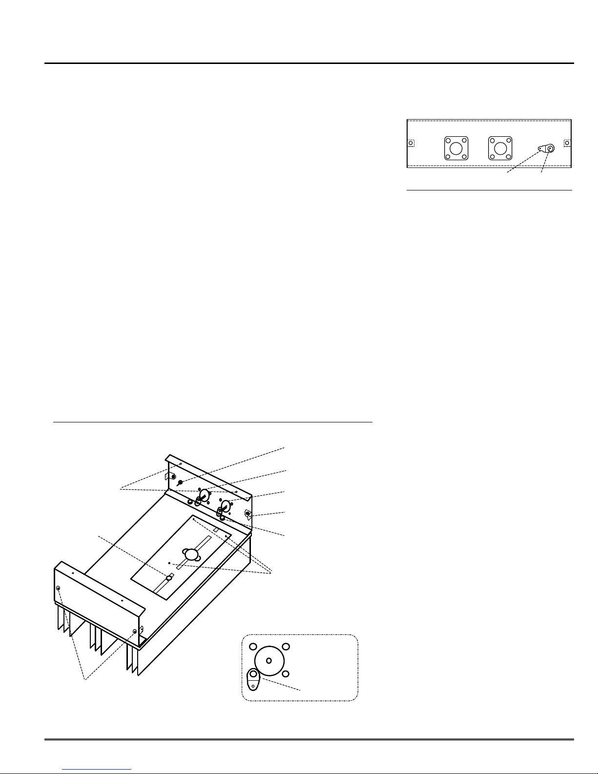
a. Set heatsink on bench, oriented as in figure 1. Note where PA
transistor is to be mounted to two
adjacent holes. Align the pc board
with the heatsink, matching the cutout for the transistor and the pc
board mounting holes with the holes
on the heatsink. Note that the heatsink
is used for several products; so there
will be extra holes to the left of the pc
board which are not used in this model.
b. Temporarily remove the pc
board, and lay it on a box or hold it in
a vise horizontally with the etched
side of the board up. Using a sharp
pick or any other convenient tool,
pick up eyelets and place them in the
small holes on the board. The heads
of the eyelets must rest flat against
the foil on the etched side of the
board. Then, using a small amount
of solder, solder the heads of the
eyelets to the foil. The eyelets connect the pc board front and rear
ground planes together at critical locations. Be sure all small holes are
thus connected through. If you lose
Pem Nuts To
Attach Covers
Hole Not Used
Be Careful Not To Remove These
Screws When Removing Cover.
Figure 1. Bottom View of Heatsink and End Plates
an eyelet, bus wire can be used.
c. Turn the pc board over, and
solder the other side of the eyelets to
the ground plane. Be sure all are
soldered, and check to make sure
none have slipped back through the
other side. If so, heat eyelet flange
on top side of board until solder on
both sides melts, and push eyelet
gently back in place. Note that it is
especially important that the 8 eyelets under the emitter leads of Q1
are properly seated and that no solder blobs protrude above eyelet
heads. This is to prevent stress on
transistor leads when it is later installed.
d. Set two #8 flat washers over
each of the 3 enclosure holes used to
mount the pc board (not the 2 transistor holes). The two washers provide
the proper thickness for the pc board
spacing needed for the transistor; so be
sure to use the ones supplied to prevent
damage to the transistor. Set the pc
board in place, and secure with three
each 6-32 x 3/8 inch thread cutting
screws. The screws go through the
Feedthru Capacitor C14
Input Connector J1
Output Connector J2
Angle Bracket (typical)
4-40 Nut with 4-40
Screw From Below
Mounting Screws
Note Position
of Solder Lug
on Connectors
pc board and spacer washers and
thread into the aluminum heatsink.
Be careful not to over tighten the screws
and strip the threads.
J2 - OUTPUT J1 - INPUT C14 - PWR
SOLDER LUG
Figure 2. Outside View of End Plate.
FEEDTHRU CAP.
e. Locate the power transistor,
and note that the collector lead is
the narrow one (see component location diagram). The collector lead
should face the right-hand side (toward connectors). Apply a small
amount of heatsink compound to the
bottom surface of the transistor, and
set it in place through the cutout in
the board.
f. Secure the transistor with two
4-40 x 5/8 inch screws inserted
through the transistor flange into the
heatsink. Use lockwashers and nuts
on the fin side of the heatsink. Align
the transistor with the board before
tightening screws.
g. There are two end plates: one
has holes for connectors. Each end
plate has two clearance holes for attachment to the heatsink and two
Pem nuts which allow the cover to be
secured. Position the end plate with
holes for connectors as shown, and
attach to heatsink with two 4-40 x
3/8 inch screws through the heatsink and two 4-40 nuts on the flange
of the end plate. In like manner, attach the end plate without connector
holes on the other end of the heatsink. Before tightening screws, align
the end plates carefully with the
edges of the heatsink so the cover
later fits neatly.
h. The cover is secured to the
chassis with four angle brackets,
which are threaded on both sides but
have slightly different dimensions on
the two sides. It is important to install them correctly. These angle
brackets should be fastened to the
inside of the chassis as shown in the
diagram, using 4-40 screws. The leg
with the shorter dimension from the
bend to the hole goes over the screw,
Page 2

©1995 Hamtronics, Inc.; Hilton NY; USA. All rights reserved. Hamtronics is a registered trademark. Revised: 1/31/00 - Page 2 -
leaving the side with the longer dimension for the cover screws to engage. Before tightening the screws,
carefully align the angle nuts flush
with the edge of the chassis. After
the angle brackets are installed, you
can set the cover over the heatsink/end plate assembly and see if
any minor adjustments are necessary to make the cover screw holes
line up with the angle brackets. It
may be necessary to temporarily
loosen the screws holding the end
plates to the heatsink to realign the
end plates farther apart or closer together.
i. Install feedthru capacitor C14
from the outside of the end plate as
shown in figure 2. Insert the capacitor through a #8 ground lug, through
the outside of the end plate, and secure with a #8 lockwasher and nut
on the inside. Tighten the nut on
the inside of the assembly with a ¼inch nut driver. Be careful not to break
the ceramic by putting force on capacitor
leads, and be careful not to over tighten
nut.
j. Attach two SO-239 or 'N' connectors to the outside of the end
plate, using three 4-40 x 1/4 inch
screws with nuts and one 4-40 x 3/8
inch screw with a ground lug and nut
for each connector. The ground lugs
should be positioned as shown in the
inset in figure 1 so that they are as
close as practical to the center lug of
the connectors.
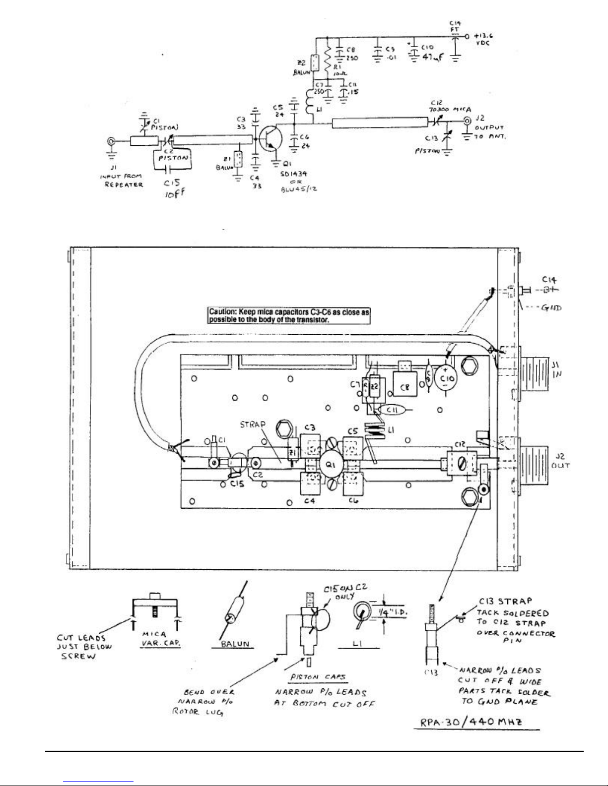
Refer to the pc board component location diagram in the rear of the manual
for the following assembly operations.
k. Solder the six transistor leads
to the pc board. It is important to
solder the entire surface of each lead
and use enough solder to form a bond
under the leads.
l. Install the metal clad mica capacitors in the exact positions shown.
The flat side with the value markings
should be up. Bend the tabs down so
they just touch the board with the
case flat against the board. Hold
each capacitor in place and solder
the tab to the board. Then, solder
each side of the metal case to the
ground plane. C3-C6 should be over
the emitter leads, as close to the
body of the transistor as possible. C7
should have its tab bent up slightly.
It acts as a free-standing terminal
above the board. Its tab does not
connect to the board, just the case.
m. Solder the mylar and disc capacitors and the electrolytic capacitor
(C9-C11) in place as shown. The
.01uF capacitor may be marked
"103". The mylar capacitor is red.
Observe polarity of electrolytic capacitor. C11 is connected from the
tab of C7 to ground.
n. Cut a brass strap 3/16 x 1
inch (approx.), and solder it down to
complete the stripline from the base
of Q1 to the hole under the position
of C2 on the diagram. (This pc board
was originally designed for another
PA which had a driver transistor
which is not used in this model.)
o. Bend the tabs of variable
mica capacitor C12 as shown, and
solder it in the exact position shown,
on a diagonal from the center contact
of J2 to the end of the collector
stripline. Its leads are bent out away
from the capacitor to reach.
p. Prepare the three piston capacitors by cutting off the two narrow
lugs from the bottom of the main body
of each capacitor. On C1 and C2,
bend the narrow lugs at the end of
the rotor straps over at a 90-degree
angle away from the capacitor.
q. Set C2 in place on the board
as shown and tack solder in place. It
will be necessary to bend the rotor
strap out away from the capacitor
body at an angle to straddle the large
hole in the board. The capacitor itself can be installed on a slight angle, and the strap will be at an angle.
Tack solder the lugs at the bottom of
the main body of the capacitor first
and then the rotor strap.
r. Likewise, set C1 in place and
solder to the board with the two lugs
at the bottom of the body of the capacitor soldered to the stripline, and
the rotor strap soldered to the ground
plane.
s. Refer to the detail drawing to
the right of C13 in the component location drawing. Note that the rotor
strap must be bent up at an angle
away from the body of the capacitor.
The excess should be trimmed off.
Install C13 on the board with the
lugs at the bottom of the body soldered to the ground plane next to the
mounting screw, and the rotor strap,
routed as directly as possible, laying
on top of the lug from C12 above the
connector pin. Tack solder thoroughly.
t. Wind coil L1 as shown in the
diagram from #18 bus wire supplied.
It is 1/4 inch inside diameter; so it
can be formed around a 1/4 inch drill
bit or other rod. L1 has three turns
barely spaced. Solder L1 leads from
the tab of C7 to the stripline in the
position shown. The bottom of the
coil should be just above the board.
u. Ferrite chokes Z1 and Z2 are
6-hole balun cores with 1-1/2 turns
of #22 bus wire threaded through the
holes in the manner shown in the
diagram. The turns go only through
the holes, not around the outside of
the core, except at the ends. Cut a
3-inch length of wire. Feed it
through a hole with about 1/2 inch
protruding, and hold this short end.
Then, thread the long end through
the adjacent hole and pull tight.
Thread through a third hole as
shown until 1/1-2 turns are complete. (Three holes are not used.)
Tack solder the leads of the balun
chokes to the board in the positions
shown. One end of Z2 is soldered to
the tab of C7.
v. Solder Z1 in place, with short
leads, from the base of Q1 to ground,
positioned as shown.
w. Strip and solder short length
of hookup wire from B+ land area on
pc board to feedthru capacitor C14.
x. Cut an 8 inch length of
miniature coax. Strip it and solder to
input of board and uhf receptacle J1.
Keep stripped lead lengths to no
more than 1/4 inch to avoid losses.
The center lead at the pc board must
be connected at the very end of the
stripline as shown.
y. Solder a short, direct piece of
3/16 inch wide brass strap from the
ground lug on J2 to the pc board
ground plane directly below J2, as
shown in the diagram. Keep the
strap as short and direct as possible
for low inductance.
z. Cut the leads of a 10pf disc
capacitor to about 1/8 inch. Carefully tack solder this capacitor to the
front side of piston capacitor C2 as
shown in the parts location diagram.
aa. Check to be sure all parts
have been installed. Check for potential short circuits and other
Page 3
©1995 Hamtronics, Inc.; Hilton NY; USA. All rights reserved. Hamtronics is a registered trademark. Revised: 1/31/00 - Page 3 -
workmanship problems. Double
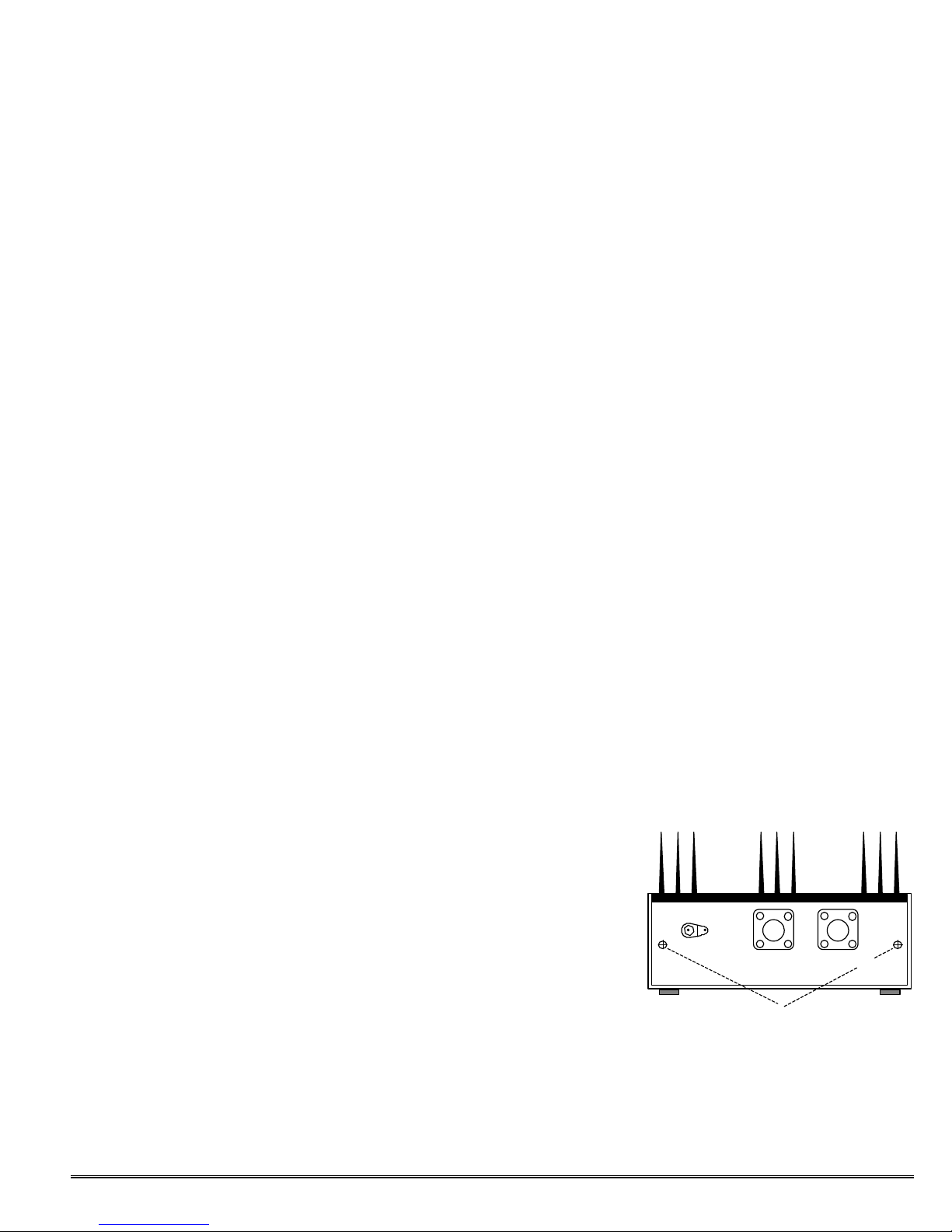
Figure 3. PA in Operating Position
check circuit to schematic diagram.
ALIGNMENT
CAUTION: Do not screw rotor screws
of piston capacitors down so far that they
touch the pc board under the body of the
capacitor. Doing so would cause a
short circuit and possibly cause damage. The screw bottoms out when
the top of the screw protrudes less
than about 1/4 inch from the top of
the capacitor.
a. Preset the variable capacitors
as follows:
• Mica capacitor C12: 1 turn from full
clockwise.
• Piston capacitor C1: 5/16 inch of
screw exposed.
• Piston capacitor C2: 3/16 inch of
screw exposed.
• Piston capacitor C13: 1/2 inch of
screw exposed.
b. Connect J1 to repeater output
or other source of 10 Watts drive.
Connect J2 through power meter to a
good uhf 50 ohm dummy load.
c. Connect regulated +13.6Vdc
power source to feedthru capacitor
C14 and power supply ground to adjacent ground lug. (If your power supply has adjustable voltage, it is better
to start tuning with about 10Vdc and
increase it to 13.6 Vdc after you determine there are no problems.)
Note: Do not retune repeater output
stage or other driving source with RPA30 connected. Driving source should
be tuned into 50 ohm load and left
alone afterwards. Input of RPA-30 is
tuned then to present 50 ohm load to
driver.
d. Apply drive to PA, and alternately adjust C1, C2, C12, and C13
for maximum output. Do this several
times to work out any interactions.
Use an insulated tool with a small
metal screwdriver bit in the end.
e. When fully tuned, the PA
should deliver about 30 to 45 Watts
with 9-11 Watts drive when using a
13.6Vdc power supply. If the dc voltage is low, the output will be less.
You may also experience considerable loss in the output coax if it is not
a good low-loss uhf type. The PA will
draw about 6 to 7 Amp at full output.
Note: It is normal for C12 to be near
full clockwise and C13 to be near minimum capacitance (screw exposed about
1/2 inch) when operating into a 50 ohm
load at 445 MHz.
COVER.
The cover slides over the PA assembly and is secured to the Pem
nuts and angle brackets on the end
plates, using eight 4-40 x ¼ inch
screws. Tighten the screws on the
bottom first to draw the cover down
tight, and then tighten the screws on
the sides. The four rubber feet
should be stuck in place about ½
inch in from each corner on the bottom of the cover. If you remove the
cover for service, be careful not to inadvertently loosen the screws on the
outside surface of the end plates
which attach the angle brackets to
the end plates.
MOUNTING.
There are several ways to install
the RPA-30, none of which is critical
as long as air flow is not restricted
around fins. The simplest is merely
to set the PA, fins up, on a shelf near
the repeater. If you wish to mount
the PA to a blank rack panel or other
vertical surface, such as a cabinet
wall, simply drill a few holes in the
cover and mount the cover. Then,
slide the PA assembly into the cover,
and secure with eight 4-40 x ¼ inch
screws. (The cover must be installed
to prevent repeater de-sense.)
POWER.
The RPA-30 requires wellregulated 13.6Vdc, free of transients,
at about 6 to 7 Amp. An 8 Amp continuous-duty power supply would
have some reserve. Use fairly short,
heavy leads to connect positive to
feedthru capacitor and negative to
adjacent ground lug. If there are any
relays or other inductive devices on
the same power supply, be sure to
put a reverse diode across the device
to absorb reverse voltage spikes ge nerated by inductive kick-back. It
would be wise to connect an 8 Amp,
fast-acting fuse in series with the PA
power lead if the power supply is capable of more than 8 Amps.
CAUTION: RF power transistors are
fully tested by the manufacturer and are
not guaranteed because they are easily
damaged by physical or electrical abuse.
They are very expensive to replace. Be
sure to use adequate precautions to avoid
damage.
OPERATION.
Once tuned, the PA will automatically operate when sufficient drive is
applied. Since it operates class C, it
will draw no current when no rf
power is applied. It is designed for
continuous duty at up to 45 Watts.
Do not operate it above that level.
Reduce drive if necessary so it will
operate at this level, which is sufficiently conservative if heatsink is not
blocked and ambient temperature is
below 100 degrees F.
REPAIR.
Should it be necessary to replace
the transistor, be sure to use an exact replacement. To remove old
transistor, carefully peel each lead
away from the pc board while appl ying heat to melt solder. Then, remove transistor from unit, and clean
excess solder from board. This is important to avoid tearing leads from
new transistor when hardware is
tightened. Also, clean off old heatsink compound, which may be dirty,
and apply a fresh coat to the new
transistor. Remember to resolder
any components removed for access
to transistor.
C14 - POWER
J1 - RF INPUT
Do Not Remove These Screws
J2 - RF OUTPUT
Page 4
©1995 Hamtronics, Inc.; Hilton NY; USA. All rights reserved. Hamtronics is a registered trademark. Revised: 1/31/00 - Page 4 -
 Loading...