

Page 1

HAMTRONICS® R139 REV C WEATHER SATELLITE RECEIVER:
INSTALLATION, OPERATION, & MAINTENANCE
GENERAL INFORMATION.
The R139 is a commercial-grade,
five-channel, crystal-controlled vhf
fm receiver optimized for operation
on the 137 MHz weather satellite
channels. It features wide i-f filters
(38 kHz modulation acceptance to
accommodate the wide deviation
used for wefax), low-noise dual-gate
FET rf amplifier and mixer stages,
and an integrated circuit i-f strip.
The R139 is crystal controlled,
and it has five channel oscillators.
All five popular satellite frequencies
are installed in the receiver. You can
easily substitute other channel crystals if you choose.
You can select a particular satellite simply by stepping the SCAN
switch on the front panel. LED's on
the panel indicate which channel is
active. An adjustable squelch circuit
allows you to determine how weak a
signal you want to hear.
If you prefer automatic scanning,
the R139 will continually scan the
five channels looking for a satellite
signal it can hear. When it hears
one, the receiver locks onto that satellite.
A tape recorder control output
can be used to activate a tape recorder automatically whenever a satellite is heard, even if you are not
home at the time. This allows you to
play back the tape whenever you
have time to reproduce the satellite
images on your computer.
The R139 is powered by 12Vdc. If
you purchase the unit wired and
tested or buy the kit with the cabinet
option, a 115Vac-12Vdc power adapter is supplied as well as a 9-pin plug
for the power, audio, and tape control connections.
CRYSTALS.
Channel crystals for the 137.100,
137.500, 137.62, and 137.9125 MHz
US NOAA satellites and the 137.400
MHz Meteor satellites are installed in
the R139 Receiver. The following
chart correlates fundamental crystal
frequency with channel frequency for
the five popular satellite frequencies
installed in the receiver.
CHANNEL CRYSTAL (MHz)
137.100 14.044444
137.400 14.077778
137.500 14.088889
137.620 14.102222
137.9125 14.134722
We can provide crystals for any
other frequencies you may want. If
you order your own crystals, be sure
to order only close-tolerance commercial grade crystals, and supply
the following specs. The receiver
uses 30 pF parallel resonant crystals
in HC-49/u holders. Crystals operate in fundamental mode at a frequency of (F-10.7)/9. Frequency tolerance is .0005%.
Note that R139 receivers manufactured before June 2005 have a
different channel lineup based on
older satellites as follows.
CHANNEL CRYSTAL (MHz)
137.300 14.066667
137.400 14.077778
137.500 14.088889
137.620 14.102222
137.850 14.127778
EXTERNAL CONNECTIONS.
Plug Assembly.
The R139 Receiver has a DB-9
male jack. The mating plug with female contacts is provided with the
cabinet kit option if you purchased a
kit receiver, or with the wired/tested
receiver, which comes in a cabinet.
If you purchased a receiver kit without the cabinet, you can provide your
own plug or not use the jack on the
board and solder wires directly to the
pc board.
The plug looks just like a jack,
except it is the opposite sex and has
a plastic hood. Hardware to assemble the hood is included. Nuts fit in
recesses in the plastic hood shells,
and one screw is installed from each
side.
Also included is hardware to assemble a clamp to fit around the cable inside the plug to provide strain
relief. It is easiest to do
this by laying one metal
clamp piece in the rear of
the shell, setting the
plug/cable assembly in
place, and then attaching
the other metal clamp
piece with a short screw.
This will position the
clamp properly. With the
COMPU TER
SOUND CARD
TAPE CO NTROL
Note: Pins 2 thru 5 are hot leads, pins 6 thru 9 are ground.
Figure 1. Terminals on Rear of Plug
one screw tightened, you can flip the
cable assembly over and install the
second screw in the other side of the
clamp.
Additional hardware is provided
for occasions where the plug is used
on a computer; the hardware being
long screws and backup plates to
hold the plug on the rear of the computer. These are not needed for this
application; so they can be discarded.
Making Connections.
Following are descriptions of the
three major connections you may
need to make. Note that the hot
wires connect to the top row of pins,
with tape recorder control connected
to pin 2, audio for a speaker and the
line input on your computer’s sound
card connected to pins 3 and 4, and
dc power connected to pin 5. All the
ground returns are connected to the
bottom row on pins 6-9. These connections are illustrated in figure 1.
Connections can be made most
easily with #22 solid or pretinned
hookup wire. It is easiest to solder
wires to the pins if you clamp the
plug in a vise and solder one row of
pins at a time. The solder cups can
be preloaded with solder. Then, to
make each connection, strip the end
of the wire about 1/8 inch, melt the
solder in the solder cup, insert the
wire, and allow the solder to cool.
DC Power.
The R139 Receiver is designed to
operate on +12 to +18Vdc. It requires about 50 mA of current with
no audio output and up to 100 mA
with audio turned all the way up.
Ideally, the R139 only needs
12Vdc. You can operate from any
12Vdc regulated power supply if you
wish. If you purchased the receiver
with a cabinet and 12Vdc power
adapter, the actual voltage will be
higher than 12Vdc, but the receiver
+
12 VDC POWE R
1 2 3 4 5
6 7 8 9
_
SPEAKER
©2005 Hamtronics, Inc.; Hilton NY; USA. All rights reserved. Hamtronics is a registered trademark. Revised: 11/11/05 - Page 1 -
Page 2

is designed to accommodate the voltage of the adapter. 12Vdc power
adapters are not regulated, and they
typically put out 18-20Vdc with no
load and drop to 12Vdc only with
their full rated load. (The adapter we
supply is conservatively rated, and
the receiver will never draw the full
rated load current of the adapter.)
The power supply or 12Vdc power
adapter should be connected with its
positive lead on pin 5 and its negative lead on pin 9. If you are using
the 12Vdc adapter, cut about an
inch off the end of the cable to get to
clean copper never exposed to the
air. Then, separate the two leads
about an inch and strip them 1/8
inch. BE VERY CAREFUL TO
OBSERVE POLARITY; THE
POSITIVE LEAD HAS A STRIPE
AND THE NEGATIVE LEAD IS
PLAIN. The lead with the small
grooves molded into it is positive,
and the smoother lead is negative. It
can be a little difficult to tell the difference, and it is important not to
reverse the polarity and damage the
equipment it is powering.
Wait to actually connect power to
the receiver; there is a procedure
later to test the polarity at first power
up.
0 WARNING: REVERSE POLARITY
WILL DAMAGE THE RECEIVER.
Also, be sure that the power source
does not carry high voltage or reverse
polarity transients on the line, since
semiconductors in the receiver can
be damaged.
Audio Output.
There are 2 sets of audio output
pins so that you can run individual
lines to both a speaker and the line
input on your computer’s sound
card. The two outputs are simply
connected in parallel, and you can
use either or both. Pins 3 and 4 are
the hot leads and pins 7 and 8 can
be used for ground returns. The
output ic in the R139 can provide up
to 1 watt of audio to a load of 8Ω or
more. (A lower load impedance
might cause distortion or overheating
at high volume levels.)
Normally, when used to drive a
computer sound card, you will want
to listen on a speaker to hear what
the signal sounds like. This is especially true during the initial acquisition period. However, most times,
you probably want the ability to
mute the speaker; so installing a
switch in line with the receiver out-
put to the speaker is handy. The
volume control can be adjusted to
whatever level is comfortable for listening and proper for the computer’s
sound card.
Tape Recorder Control.
The squelch circuit in the R139
Receiver continually looks for an active satellite. If it hears one, it stops
on that channel and turns on a
switching transistor. The transistor
output can be used to activate a tape
recorder, allowing you to play back
the tape into your computer’s sound
card whenever you have time to reproduce the satellite images on your
computer. The transistor can sink
up to 50 mA of positive current to
ground, with a voltage not to exceed
15Vdc.
Figure 2 illustrates one possible
method of activating a tape recorder.
If your tape deck has a motor circuit
which returns to ground which is
common with the receiver ground
and draws less than 50 mA, you can
use the transistor directly to switch
the motor on and off. If the motor
circuit draws more than 50 mA or if
you are not sure about polarity, current, or voltage, then adding a small
external relay wired as shown will
provide a buffer for the output transistor.
In either case, be sure to connect
a transient protection diode across
the device you are switching with the
transistor. Motors and relays generate a large reverse transient voltage
when the current path is broken.
Such transients will damage any
transistors or ic's they reach. Providing a diode, as shown, to conduct
and shunt this reverse polarity current will prevent the voltage from
building up to a high enough level to
do any damage.
If you have your tape recorder ptt
switch wired to respond to the tape
recorder control from the receiver,
then you need to somehow disable
this motor control to allow the motor
to operate normally for playback.
You can do this by
unplugging the cable going to the ptt
jack on the tape
recorder; but a
nicer method
would be to add a
toggle switch to
short the relay
contacts together
when you want to
XSTR Q1 IN
R139 RECEIV ER
Figure 2. Circuit To Activate Tape Recorder
play back the tape.
Antenna Connections.
The success of reception is very
much dependent on having a good
antenna. The ARRL Weather Satellite
Handbook, which we sell, is a good
source of information on building antennas. Good quality, low-loss 50Ω
coax should be used because the
satellite signals are weak. The coax
should be plugged into the BNC jack
on the rear of the receiver.
If you are using large diameter
coax, it may be necessary to use a
UHF-BNC adapter. Such adapters
are shown in the rear of our catalog.
Another alternative is to use a short
length of smaller diameter, more
flexible, coax between the main cable
and the receiver. That cable can
have a BNC plug on one end and a
UHF plug and double female adapter
on the other.
If you use a preamp, such as our
LNG-137, you can overcome some
cable losses by installing the preamp
right up at the antenna. This establishes a low noise figure before going
through the loss of the cable.
Note that we do not recommend
trying to feed B+ to power the preamp through the coax as some try to
do. It doesn't pay to try to save the
small cost of light weight hook up
wire and mess up the performance of
the preamp in the process. We have
tested many such methods of feeding
B+ on the coax, and we have not
found a very good way to do it without some compromise in performance.
INITIAL TESTING AT FIRST
POWER UP.
Following is a safe start-up procedure, assuming you either built a
kit or are using a power supply setup
the first time. This procedure will
check the voltages and polarity to be
sure that no damage will occur.
0 CAUTION: Reverse polarity or
voltage transients from relays, motors, etc. can damage semiconduc-
+12 VDC
TO TAPE R ECORDER
2
6
ADDED REL AY
TRANSIENT PROTECTION DIODE
©2005 Hamtronics, Inc.; Hilton NY; USA. All rights reserved. Hamtronics is a registered trademark. Revised: 11/11/05 - Page 2 -
Page 3

tors. Use only proper, filtered power
supplies of the correct voltage, and
check to make sure any inductive
devices, such as motors or relay
coils, operating from the same power
source have transient absorbing diodes connected across them.
Input Voltage Range.
The R139 has an 8 volt regulator
built in. The only circuit which uses
power taken before the regulator is
the audio output ic. These two
branches both may operate with filtered, but not necessarily regulated,
power with a voltage up to 18 Vdc
and having a little ripple. Filtering
circuits in the receiver can eliminate
a little ripple, the type you might get
from an unregulated 12Vdc power
adapter. They can also contend with
some voltage variation with load current, which you ordinarily see with
changes in audio output level.
It is normal for the 12Vdc power
adapter to put out about 20Vdc with
no load at all and drop to 12Vdc only
at full load. In the case of the very
conservatively rated adapter we supply with cabinets, the receiver never
draws enough current to draw the
voltage down to 12V.
Start-up Voltage Checks.
Assuming you have wired up the
9-pin plug to the power adapter or a
12Vdc power supply and have double
checked the polarity, do the following.
a. Before plugging in the power
plug, turn off the front panel POWER
switch.
b. Connect the 9-pin plug, and
connect a dc voltmeter from the lefthand lug of POWER switch S2 on the
pc board. The voltmeter should
show a positive voltage of about
20Vdc if using the 12Vdc power
adapter or about 12Vdc or 13.6Vdc if
using a regulated power supply.
0 Pay special attention to verifying the correct polarity before turning on the POWER switch. Damage
to the receiver will occur if the polarity is reversed.
c. Turn on POWER switch, and
turn the VOLUME control fully counterclockwise. If you are using the
12Vdc power adapter, the voltage will
drop to about 17-18Vdc. If you are
using a regulated power supply, the
voltage should not change.
d. Connect a speaker and turn
VOLUME control fully clockwise.
With lots of white noise, the supply
voltage should drop to about 1516Vdc if using the 12Vdc power
adapter or remain constant if using a
regulated power supply. Turn down
VOLUME when done.
e. Reconnect positive lead of
voltmeter to the lead of ferrite bead
Z1, just above the POWER switch on
the pc board. This carries regulated
voltage to the rest of the receiver; it
should be close to +8Vdc.
f. This completes preliminary
tests. Now it is safe to operate, or in
the case of a kit, to align the receiver.
ALIGNMENT.
Equipment needed for alignment is
an rf signal generator and an fet voltmeter. (If you have one, analog meters
make it easier to observe tuning.)
Slug tuned coils should be adjusted with the proper .062" square
tuning tool to avoid cracking the powdered iron slugs. See A28 Tuning
Tool in catalog.
Variable capacitors should be adjusted with a plastic tool with a small
metal bit on the end. See A2 Tuning
Tool in catalog.
a. Connect power and speaker to
J1.
b. Turn on power, and click the
SCAN switch to the left several times
to get to the channel which is about
in the center of the tuning range,
which presumably is channel 3. The
LED's should indicate which channel
is selected
c. Set SQUELCH control R2
fully counterclockwise and VOLUME
control R1 for a comfortable listening
level.
d. Connect dc voltmeter to oscillator test point TP-1, which is the top
lead of R29, just to the right of the
BNC jack. Alternately adjust L4 and
L5 for maximum dc voltage. (Typical
indication is roughly +0.7 to 1.8
Vdc.)
e. Connect stable signal generator to 10.7 MHz test point TP-2, the
top lead of R17 next to mixer Q3.
Use a coax clip lead and a .01 µf disc
capacitor to block the dc. Connect
coax shield to pcb ground. Set generator to exactly 10.700 MHz. Use a
frequency counter or synthesized
signal generator. Set the signal generator level high enough to provide a
full quieting signal. No modulation is
needed.
f. Connect dc voltmeter to test
point TP-4, which is the top of R6
(under i-f amplifier ic U1). Adjust
discriminator coil L8 for +3.3Vdc.
g. Connect signal generator to
BNC jack J2.
Note: The following procedure assumes you are using the five channel
frequencies normally installed in the
R139 Receiver for the US and Russian weather satellites. If not, use
the appropriate channel frequencies
of your crystals when doing the
alignment procedure which follows.
h. Adjust signal generator to exact channel frequency of your mid
channel. We assume channel 3,
which is 137.500 MHz. Turn output
level up fairly high. Adjust frequency
trimmer capacitor C33 to net the
crystal to channel frequency, indicated by 3.3V at test point TP-4.
i. Repeat this adjustment procedure for the other 4 channels. Use
the STEP position of the SCAN switch
to change channels. Following is a
list of the capacitors to adjust and
frequencies to set the signal generator.
Channel Frequency MHz) Trimmer
1 137.100 C31
2 137.400 C32
3 137.500 C33
4 137.620 C34
5 137.9125 C35
Note: To adjust the mixer and
front end, use an fet voltmeter on the
2Vdc range with test point TP-3,
which is the top lead of R9. The
voltage at this point is inversely proportional to the amount of noise detected in the squelch circuit; so it
gives an indication of the quieting of
the receiver. A signal peak is indicated by maximum dc voltage.
The reading also varies with the
setting of the SQUELCH control.
Best results are obtained with the
SQUELCH control set just counterclockwise enough to open the
squelch. That allows the audio to be
heard and provides a good range of
dc voltage readings with changing rf
signal levels.
With no signal, the test point voltage varies from about -1.5Vdc with
the SQUELCH control fully open
(CCW) to about -2.5Vdc with it fully
closed (CW). With the SQUELCH
control adjusted to where the
squelch first opens, the test point
voltage is about -1.5Vdc.
We tell you all this just so you
have a feel for what is happening as
you tune. A voltage from the noise
detector is summed with a voltage
from the SQUELCH control, and the
tuning action will move the test point
©2005 Hamtronics, Inc.; Hilton NY; USA. All rights reserved. Hamtronics is a registered trademark. Revised: 11/11/05 - Page 3 -
Page 4

voltage in a positive direction from a
reference where the SQUELCH control sets it.
Under these conditions, with the
squelch just opened with no signal,
the dc voltage will vary from about -
1.5Vdc with no signal to about
+0.65Vdc with a full-quieting signal.
Although the test point voltage
changes polarity as the signal level
increases, the crossover point at 0Vdc
will occur with a fairly full quieting
signal, about 0.6µV with a fully tuned
receiver. Therefore, using a 1.5 or 2
Vdc range with negative polarity on
the voltmeter will allow you to see all
of the tuning range you need for
alignment.
A weak to moderate signal is required to observe any change in
noise. If the signal is too strong,
there will be no change in the reading as tuning progresses; so keep the
signal generator turned down as the
sensitivity of the receiver increases
during tuning. This will be in the
negative voltage range.
j. Select the channel closest to
the center of the frequency range of
channels to be used. Usually, this
will be channel 3 as described earlier.
k. Set signal generator to channel frequency. Set attenuator for
relatively weak signal, one which allows some white noise so changes in
signal strength allow variation in the
test point indication. Peak coils in
the following order, and then repeak
them, working out any interactions
between them.
• Do L3 first, because it benefits
most from tuning.
• Then, do L6 and L7.
• Then, do L1, L2, and L3.
When properly tuned, the sensitivity should be about 0.2µV for
12dB SINAD and about 0.25µV for
20dB quieting.
l. Check operation on the other
channels. They should all have
about the same sensitivity.
m. This completes alignment. If
you purchased the unit as a kit, you
can now install the pc board in its
cabinet.
OPERATION.
Operation of the receiver is fairly
obvious, but we will comment on several features of interest.
Normally, when used to drive a
computer’s sound card, you will want
to listen on a speaker to hear what
the signal sounds like. The VOLUME
control can be adjusted to whatever
level is comfortable for listening and
proper for the computer’s sound
card. This is especially true during
the initial acquisition period. However, most times, you probably want
the ability to mute the speaker; so
installing a switch in line with the
receiver output to the speaker is
handy.
/ Caution: The audio output
stage is rated at 1W with a speaker
Ω
having an impedance of 8
To avoid damage from overheating, do
not run into loads below 8
very high audio levels for extended
periods. The audio output ic normally
gets very warm, but not so hot that
you can't touch it briefly without discomfort.
To adjust the SQUELCH control,
turn it clockwise just a little beyond
the point where the squelch closes
with no signal (just noise). The
squelch circuit has adjustable sensitivity – the further clockwise you set
the control, the stronger the signal
must be to open the squelch. This is
handy to set how strong you want
the satellite signal to be before the
tape recorder turns on. Be careful
not to set it too far clockwise,
though, because the squelch might
not open even with a strong signal.
Channel selection is done with
the SCAN switch. Normally, you may
wish to leave it in the center MAN
position, which keeps the receiver
locked on the current channel. To
change channels manually, flick the
switch to the left STEP position once
for each incremental change you
wish to make. To move over several
channels at once, you can hold the
switch in the STEP position until you
reach the desired channel.
If you wish to scan all channels
and stop when the receiver discovers
a satellite within reception range, set
the SQUELCH control just above the
point where the squelch closes with
no signal. Then, set the SCAN
switch to AUTO.
0 Note: It is possible that the
channel selection/scan circuit will not
operate properly until power has been
applied for several hours the first time
it is used. Due to high impedances,
an electrolytic capacitor in the scan
circuit must have low leakage, which
requires that the unit be in operation
regularly. The solution is to leave the
power on overnight. After being in
storage for a long time, electrolytic capacitors require re-forming to have low
or higher.
Ω
or run at
leakage. Once the unit is in operation
regularly, this should not be a problem. If the scan circuit does not scan
normally after power has been applied more than one or two days, contact us at [email protected].
TROUBLESHOOTING.
General.
The usual troubleshooting techniques of checking dc voltages and
signal tracing work well in troubleshooting the receiver. DC voltage
charts and a list of typical audio levels are given to act as a guide to
troubleshooting. Although voltages
may vary widely from set to set and
under various operating and measurement conditions, the indications
may be helpful when used in a logical troubleshooting procedure.
Signal Tracing.
If the receiver is completely dead,
try a 10.700 MHz signal applied to
test point TP-2 (the top lead of R17)
with a coax cable clip lead and a
.01µf blocking capacitor. You should
be able to hear the quieting effect of
a 4µV carrier at 10.700 MHz. (If you
have a SINAD meter, the 12 dB
SINAD sensitivity should also be
about 4µV.) Also, check the 10.245
MHz oscillator with a scope or by listening with an hf receiver or service
monitor.
A signal generator on the channel
frequency can be injected at various
points in the front end. If the mixer
is more sensitive than the rf amplifier, the rf stage is suspect. Check
the dc voltages looking for a damaged fet, which can occur due to
lightning damage or due to voltage
transients or reverse polarity on the
dc power line. It is possible to have
the input gate (gate 1) of the rf amplifier fet damaged by high static
charges or high levels of rf on the antenna line with no apparent change
in dc voltages, since the input gate is
normally at dc ground.
If audio is present at the volume
control but not at the speaker, the
audio ic may have been damaged by
reverse polarity or a transient on the
B+ line. This is fairly common with
lightning damage. If no audio is present on the VOLUME control, the
squelch circuit may not be operating
properly. Check the dc voltages, and
look for noise in the 10 kHz region,
which should be present at the top
lead of R8 (U1-pin 11) with no input
signal. (Between pins 10 and 11 of
©2005 Hamtronics, Inc.; Hilton NY; USA. All rights reserved. Hamtronics is a registered trademark. Revised: 11/11/05 - Page 4 -
Page 5

U1 is an op-amp active filter tuned to
10 kHz.)
Current Drain.
Power line current drain normally
is 45-50 mA with volume turned
down or squelched and up to 100
mA with full audio output.
If the current drain is approximately 100 mA with no audio output,
check to see if voltage regulator U3 is
hot. If so, and the voltage on the 8V
line is low, there is a short circuit on
the +8Vdc line somewhere and U3 is
limiting the short circuit current to
100mA to protect the receiver board.
If you clear the short circuit, the
voltage should rise again. U3 should
not be damaged by short circuits on
its output line; however, it may be
damaged by reverse voltage or high
transient voltages. To track down
short circuits, you can temporarily
disconnect various ferrite beads to
isolate parts of the circuitry.
Test Point Indications.
The following measurements are
typical of those found at the three
built-in test points used for alignment. They can vary considerably
without necessarily indicating a
problem, however; so use with other
findings to analyze problems, don't
jump to conclusions.
Oscillator Test Point TP-1
Approx. +0.7 to 1.8 Vdc with osc running and
output tuned circuits aligned. Varies as L5
and L6 are aligned. 0Vdc with oscillator not
running or coils not properly aligned.
Signal Strength Test Point TP-3
With full noise (no signal), voltage varies
from about -1.3Vdc with squelch control
fully ccw to about -2.4Vdc with squelch
control fully cw.
With squelch control adjusted until squelch
just opened, approx. -1.4Vdc. Under this
condition, if signal is introduced, TP-3 voltage will increase up to +2.1Vdc, proportional to signal strength.
Discriminator (Freq.) Test Point TP-4
Varies with frequency of input signal. Voltage at this point normally adjusted for
+3.3Vdc with a signal exactly on frequency.
Can vary a little without being a problem.
Typical Dc Voltages.
The dc levels shown in the tables
were measured with an fet voltmeter
on a sample unit with +12Vdc power
applied. All voltages may vary con-
siderably without necessarily indicating trouble. The chart should be
used with a logical troubleshooting
plan.
All voltages are positive with respect to ground except as indicated. Voltages are measured with
no signal applied but with crystals
installed and oscillators running
properly and with squelch open
unless otherwise specified.
Transistor Measurements
Xstr Cond. E(S)
Q1
sq. open
sq. closed
Q2
Q3
Q4-
Q8
Q9
selected
not select.
drive
no drv
0.7 to 1.8 0 8 -
(G1)
0
0
0 0 8 4
0 0 8 0
2 2 8 0 0 8 -
0 0 8 -
(D) G2
0.7 0 0 - -
-
IC Measurements
U1-1: 8V
U1-2: 7.6V
U1-3: 7.8V
U1-4: 8V
U1-5: 7.7V
U1-6: 7.7V
U1-7: 7.7V
U1-8: 8V
U1-9: 3.3V
(On freq.;
varies w/freq)
* Voltage varies with power supply voltage. Values shown for 12Vdc input. Values
will be higher with "12DC" power adapter.
U1-10: 0.76
U1-11:
2.1V U1-12:
0.7V
(squelch
just closed)
U1-13:
+7.6v (sq
closed),
0V (sq
open)
U1-14: 0V
U1-15: 0V
U1-16:
1.8V
U2-1: 7V*
U2-8: 6V
U2-14:
12V*
Note that logic circuits are not
covered in the tables because
high/low level information is indicated by symbols on the schematic
diagrams.
Typical Audio Levels.
Following are rough measurements of audio circuits, using an oscilloscope. Measurements were
taken with no input signal, just white
noise so conditions can be reproduced easily.
MAINTENANCE.
Repairs.
Since the pc board uses plated
through holes, some care must be
taken in desoldering to remove parts.
A vacuum desoldering tool or solder
wick braid is helpful. If you don't
have tools which make it easy to remove ic's and other multiple lead
parts from the board, you can cut
the individual leads at the base of
the part and then unsolder leads individually after the part is cut free.
Frequency Adjustment.
Crystals normally age. Although
the amount of long-term frequency
drift due to aging is usually less
than 1kHz/year at the channel frequency, it is normal to check the frequency of each channel oscillator
once every year or two to see if it is
necessary to trim it back on frequency.
To do the checks and adjustments, refer to steps (e.) through (i.)
of the ALIGNMENT procedure, found
earlier in the manual.
Audio Test Point Normal Level
U1-9 or
TP-4 (Discriminator)
U1-11, top of R8
(noise ampl output)
Top of Volume
Control R1
U2-3 (af ampl input) 0 to 150mV p-p
U2-6 or J1-3&4
(af ampl output)
2V p-p audio
4V p-p noise
150mV p-p audio
(dep. on volume)
0 to 4V p-p audio
THEORY OF OPERATION.
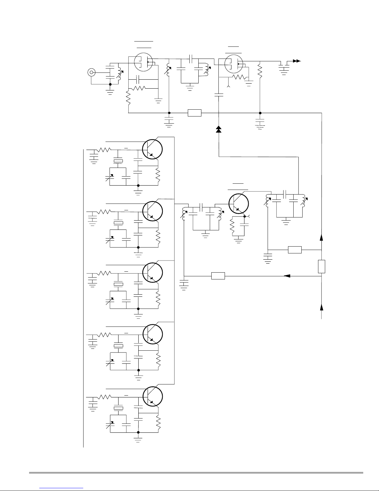
Refer to the schematic diagram in
figure 4, sheet 1. The vhf signal from
the antenna is amplified by low-noise
dual-gate fet Q2. Antenna impedance matching is provided by the
tuned circuit at the input of Q2. A
double-tuned output tank circuit
provides image rejection and rejection of interference from out of band
signals. First mixer Q3 converts the
137.xxx MHz signal to the 10.7 MHz
i-f, and ceramic filter FL1 passes the
i-f signal to i-f amplifier ic U1, shown
on sheet 2 of the schematic.
The injection signal for the first
mixer is obtained from one of five
crystal oscillators, Q4-Q8, which are
selected by the scan circuitry shown
on sheet 2. The 14.xxx MHz signal
from the selected oscillator is tripled
once in the double-tuned tank circuit
at the collector of the oscillator (L4L5) to the 42 MHz range. This frequency is tripled again in tripler Q9
to the 126 MHz range.
Refer now to schematic figure 4,
sheet 2. The 10.7 MHz first i-f signal
is further processed in i-f amplifier ic
U1. Pins 1 and 2 form a 10.245 MHz
oscillator. This signal is used in the
second mixer within the ic to convert
the input signal at pin 16 to 455 kHz
at pin 3. A wideband ceramic filter
between pins 3 and 5 provides adjacent channel selectivity. Regulated
©2005 Hamtronics, Inc.; Hilton NY; USA. All rights reserved. Hamtronics is a registered trademark. Revised: 11/11/05 - Page 5 -
Page 6

8Vdc power is applied to the ic at pin
4. The 455 kHz i-f signal is converted to audio by a quadrature detector at pins 6-8. Quadrature coil
L8 sets the center frequency of the
detector, and resistor R4 sets the
modulation acceptance bandwidth.
It is important to note that all the
circuits along the bottom of the ic on
the schematic are referenced to B+
bus and not to ground. C6 is a master bypass capacitor which ties this
B+ bus to ground all at one point.
C7 and C8 bypass parts of the internal circuitry in the detector.
The signal path continues right to
left across the top of U1 on the schematic. Detected audio or white noise
at pin 9 is applied to the VOLUME
control through blocking capacitor
C12 and partial de-emphasis network R5/C11.
Pin 14 is the collector of a squelch
muting transistor switch inside the
ic. This transistor is controlled by
the dc signal at pin 12 and effectively
grounds the audio line to squelch it
when only noise is present in the detected signal. The signal at pin 12 is
derived from two sources, bias from
the SQUELCH control and detected
noise from pin 11 through voltage
doubler rectifier C15, CR1, CR2.
C16 averages signal peaks. Combined with hysteresis action in the ic
at pin 12, this prevents the squelch
from bouncing on and off with fading
signals and makes the squelch action positive acting.
Inside the ic, there is an op amp
between pins 10 and 11 which acts
as an active bandpass filter peaked
at about 10 kHz, looking for white
noise above the normal audio frequency range. The active filter is
formed by R6, R7, R8, C13, and C14.
Audio from the VOLUME control
is applied to the speaker and computer’s sound card through power
amplifier U2. C5/R3 is a parasitic
suppression network, which normally is not used in this application,
but we left space for it just in case.
Channel selection is done by the
scan circuit, consisting of U4 and
U5. Ring counter U5 is clocked at a
4 pps scanning rate by U4B-U4C.
This turns on each channel for a ¼
Sec period, which is long enough for
the receiver squelch circuit to respond if it hears a signal for that satellite frequency, even if there is some
fading. When pin U5-13 is enabled
(low), U5 continually sequences from
one output to another. The counter
stops when the enable signal at pin
13 is removed.
The selected output from the
counter is a positive current to operate the appropriate LED and channel
oscillator. The output voltage is limited by the LED to about 2Vdc. This
voltage acts as bias for the base of
the selected oscillator transistor
shown on sheet 1.
Scanning control is done by ORgate U4-D. When the SCAN switch is
in the AUTO position, pin 12 is held
low, and the output of U4-D is controlled by the COS (carrier operated
switch) signal from the squelch circuit. When the squelch is closed, the
ring counter is enabled and it
changes channels. When the
squelch circuit opens due to a received signal, the ring counter stops
on that channel.
With the SCAN switch set to MAN,
a positive voltage from R12 is fed to
U4 pin 12 constantly to lock on the
enable signal for the ring counter.
However, the positive voltage through
R13 disables the clock oscillator; so
the ring counter stays on one channel. When you want to change
channels, operating the SCAN switch
to the STEP position grounds U4-B
and allows the clock to run. If you
flick the switch momentarily to the
STEP position, the clock only cycles
once. If you hold the switch in the
STEP position, the clock continues to
run until the switch is released.
PARTS LIST.
Ref Desig Description (marking)
C1-C3 4.7 uF electrolytic ➊
C4 47 µF electrolytic ➊
C5 not used
C6-C8➐ 0.1 µF
C9➐ 220 pF
C10 68 pF
C11➐ .0047 µF
C12 0.15 µF mylar (red)
C13-C14➐ .001 µF
C15 0.15 µF mylar (red)
C16 2.2 µF electrolytic ➊
C17➐ .0047 µF
C18 0.47 µF electrolytic ➊
C19➐ .0047 µF
C20➐ 27 pF
C21 68 pF
C22-C23➐ .0047 µF
C24➐ 18 pF
C25➐ 0.5 pF
C26➐ 15 pF
C27➐ 4 pF
C28-C30➐ .0047 µF
C31-C35 2-30 pF variable ➋ (green)
C36-C40➐ 22 pF
C41-C50➐ 150 pF
C51-C55➐ .0047 µF
C56 82 pF
C57➐ 1 pF
C58 82 pF
C59➐ .0047 µF
C60➐ 27 pF
C61➐ 0.5 pF
C62➐ 22 pF
CR1-CR2 1N4148 diode ➊
DS1-DS5 T-1 red L.E.D. ➊
FL1 10.7 MHz cer filter (10.7MA)
FL2 455 kHz ceramic filter (455B)
J1 DB-9 male jack
J2 BNC right-angle jack
L1-L3 2½ turn slug-tuned (red)
L4-L5 6½ turn slug-tuned (blue)
L6-L7 2½ turn slug-tuned (red)
L8 455 kHz i-f xfmr
(T1003 or RLC-352)
Q1 2N3904
Q2-Q3 BF998 mosfet ➊ ➎
Q4-Q9 2N5770 ➊
R1-R2 100K panel mount pot
R3 not used
R4➐ 15K
R5➐ 510K
R6 4.7K ➌
R7➐ 680Ω
R8➐ 510K
R9➐ 150K
R10 150K
R11➐ 6.8K
R12➐ 27K
R13➐ 150K
R14➐ 330K
R15-R16➐ 100K
R17 100K ➌
R18 270Ω
R19-R23➐ 6.8K
R24-R28➐ 270Ω
R29 1K ➌
R30➐ 3.9 meg
S1 mom-off-on toggle sw ➍
S2 on-on toggle switch ➍
U1 MC3361BP IF ampl ➊
U2 LM-380 audio out ➊
U3 78L08 voltage regulator ➊
U4 4001B quad nor gate ➊ ➎
U5 4017B ring counter ➊ ➎
Y1 137.100 ➏ (14.044,444)
Y2 137.400 ➏ (14.077,778)
Y3 137.500 ➏ (14.088,889)
Y4 137.620 ➏ (14.102,222)
Y5 137.9125 ➏ (14.134,722)
Y6 10.245 ➏
Z1-Z5 Ferrite bead, prestrung
Notes:
➊ Observe polarity.
➋ Install flat end oriented as shown.
➌ Leave 1/16" test point loop at top
and face as shown.
➍ There are two different switches.
➎ Caution: Static sensitive part!
➏ Caution: Fragile part!
➐ Surface mount part under board
©2005 Hamtronics, Inc.; Hilton NY; USA. All rights reserved. Hamtronics is a registered trademark. Revised: 11/11/05 - Page 6 -
Page 7
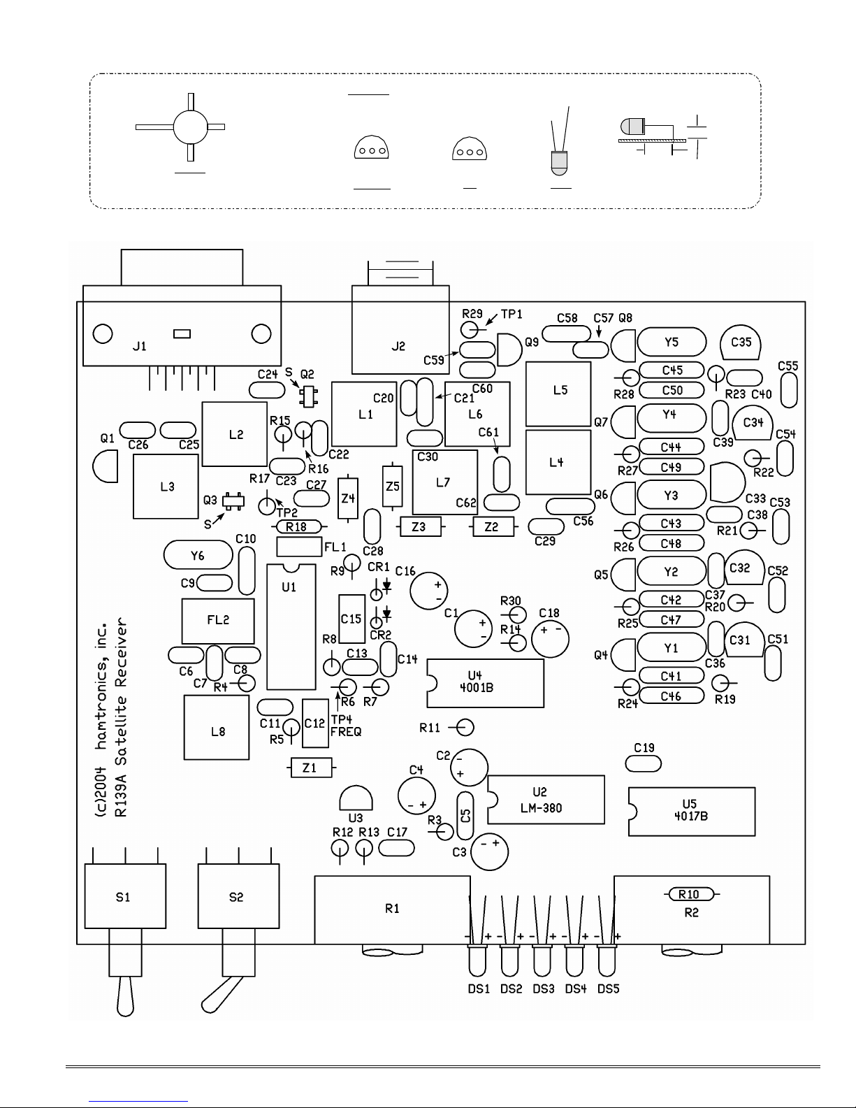
SO URCE
TOP VIEWS
LONG LEAD = ANODE (+)
- +
DRAI N
GATE 1
GATE 2
Q2 & Q3
LETTE RING ON F.E.T. MUST BE
VISIBLE FROM TOP OF BOARD
Q1, Q4-Q9
5/16"
OUTPUT GND INPUT E B C
U3
L.E.D.
1/8"
©2005 Hamtronics, Inc.; Hilton NY; USA. All rights reserved. Hamtronics is a registered trademark. Revised: 11/11/05 - Page 7 -
Figure 3. R139 Component Location Diagram
Page 8
ANTENNA
INPUT
C20
J2
C21
C51
C31
Q2 - RF
L1
R16
R15
Q4 - OSC CHAN
1
R19
Y1
C41
C46
C36
AMPL
C22
C23
R24
C24
L2
C25
C26
Z4
L3
C27
Q3 -
MIXER
R17
10.7 MHZ
TP-2
+8VDC
OSC
INJ
Q9 -
TRIPLER
C28
R18
FL1
C61
10.7 MHZ
IF SIGNAL
TO U1-16
(SHEET 2)
Q5 - OSC CHAN
C52
R20
Y2
C32
Q6 - OSC CHAN
C53
R21
Y3
C33
Q7 - OSC CHAN
C54
R22
Y4
C34
C37
C38
C39
2
3
4
C42
C47
C43
C48
C44
C49
R25
R26
R27
L4
C56
C29
C57
C58
L5
Z2
R29
TP-1
C59
L6
C30
C60
C62
L7
Z5
+8VDC FROM
VOLTAGE REGUL.
Z3
(SHEET 2)
Q8 - OSC CHAN
C55
R23
Y5
C35
OSC CONTROL FROM
SHEET 2
©2005 Hamtronics, Inc.; Hilton NY; USA. All rights reserved. Hamtronics is a registered trademark. Revised: 11/11/05 - Page 8 -
5
C40
C45
C50
R28
Figure 4, Sheet 1. R139 Weather
Satellite Receiver, Schematic Diagram.
Page 9

250 mS ec
CLOCK
STEP
S1 - SCAN
HI OVERRIDES COS
FROM SQUELCH
HI ENABLES SCAN
COS (HI =
SQUELCHED)
10.7 MHZ SIGN AL
FROM SHEET 1
16 15 13
IF INPUT COS SQUELCH GATE NOIS E AMPL AF OUT MUTE
OSCILLATOR ----------- MIXER ----- ---------- ---------D ETECTOR-------
1 2
C10
Y6
MAN
R13
AUTO
R12
12
13
+8VDC
+8VDC
R2
SQUELCH
R10
cw
_
C16
U1 - MC3361 - IF A MPL/DETECTOR/SQU ELCH
3 4 5 6 7 8
C9
U4-B
6
5
C17
U4-D
11
OR
1
2
+
3
INV
U4-A
R9 SIG. LEVEL
CR1
C15
12 11 10 9 14
R11
4
CR2
C14
R8
C8
C18
_
TP-3
+
C13
C7
R14
8
9
U4-C
R30
Q1 - SWITCH
R7
R6
R4
10
FREQ. TP- 4
C12 R5
C11
L8
+8VDC
R1
VOLUME
14
CL
13
EN
1
Q5
15
RST
U5 - 4017
RING COUNTER
16
VCC VDD
C19
P/O U4 - 4001
VCC VDD
14
U2 - LM-380
2
AUDIO OUTPU T
3-5,7, 10-12 1 14
+
_
C3
Q0
DS1
Q1
DS2
Q2
DS3
Q3
DS4
Q4
DS5
8
7
TAPE RECORDER CONTROL
(GND = SQUELCH OPEN)
C4
8
+
C5
R3 FL2
CH1
CH2
CH3
CH4
CH5
OSC CONTROL
TO SH EET 1
J1 PIN 2
_
SPKR OUT
J1 PINS 3-4
POWER SUPPLY &
SPEAKER GND
J1 PINS 6-9
+8VDC TO S HEET 1
& CIRCUITS ABOVE
©2005 Hamtronics, Inc.; Hilton NY; USA. All rights reserved. Hamtronics is a registered trademark. Revised: 11/11/05 - Page 9 -
+12 TO 16 VDC INPU T
J1 PIN 5
C6
Z1
U3 - 78L08
8-VOLT RE G.
+
_
C1
C2
+
_
S2 - POWER
Figure 4, Sheet 2. R139 Weather Satellite Receiver, Schematic Diagram.
 Loading...