

Page 1
©1995 Hamtronics, Inc.; Hilton NY; USA. All rights reserved. Hamtronics is a registered trademark. Revised: 2/1/00 - Page 1 -
HAMTRONICS® VHF RECEIVING CONVERTERSHAMTRONICS® VHF RECEIVING CONVERTERS
CONSTRUCTION, ALIGNMENT, & INSTALLATION INSTRUCTIONSCONSTRUCTION, ALIGNMENT, & INSTALLATION INSTRUCTIONS
GENERAL DESCRIPTION.
The CA( ) series of VHF Receiving Converter modules are designed
to amplify and convert the frequency
of vhf signals in specific bands to 2830 MHz.
The input and output connectors
are BNC type when the unit is supplied in a case and RCA type when
the unit is supplied without a case.
The Converter is used to convert
vhf frequencies in a block down to
28-30 MHz so they can be heard on
a 10 meter receiver.
CONSTRUCTION.
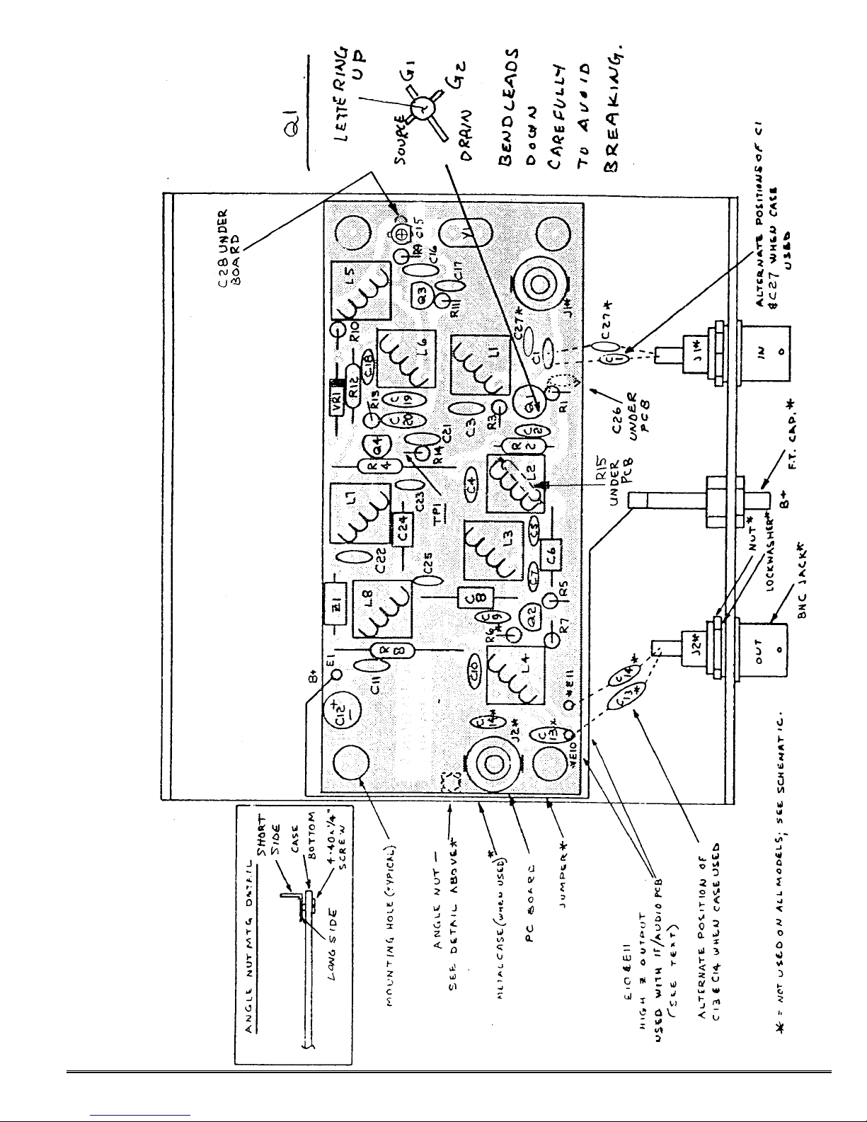
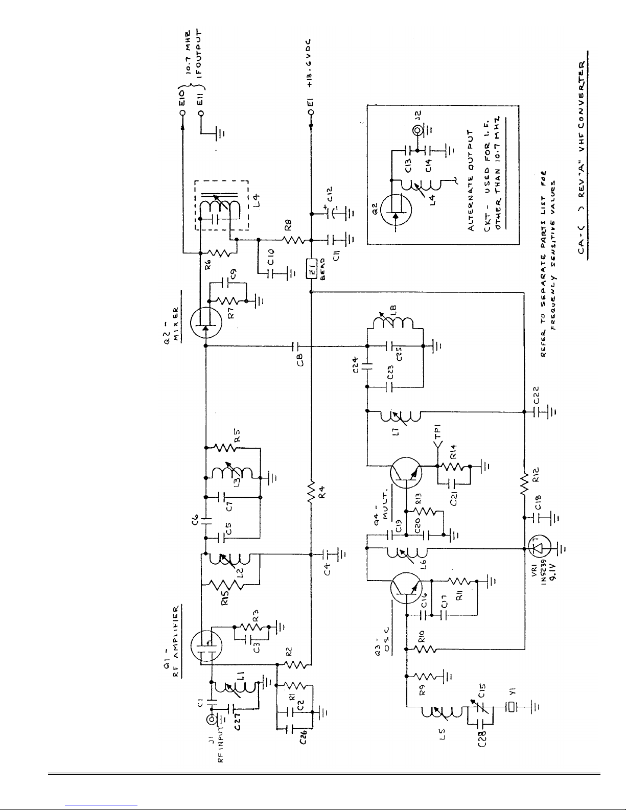
Refer to schematic and component location diagrams during assembly and the list of frequencysensitive parts for your particular
model. Note that there are variations depending on the use and
packaging of the module. The correct parts have been supplied for
your particular model to avoid confusion.
General Construction Notes.
Proper polarity must be observed
on diodes and electrolytic capacitors. The banded end of a diode is
the cathode. This corresponds to
the bar on the diode schematic symbol used on component location diagram.
Resistors and diodes installed
vertically on a pc board are shown
on component location diagrams as
a circle, denoting the position of the
body of the component, with a line
representing the top lead going over
to the other pc board hole.
Capacitors may be marked in pf
with two significant figures and a
multiplier, much as resistors are
marked. For instance, a 220 pf capacitor may be marked "221", a .001
uf capacitor may be marked "102"
(1000 pf) or it may be marked 1nK
(for 1 nano-farad with 10% "K" tolerance), and a .01 uf capacitor may
be marked "103" (10,000 pf).
A tuning tool of the proper type
must be used to avoid cracking the
slugs in the coils. This is a .060"
square slot type tool. (See "A28
Tuning Tool" in catalog.) The slugs
are teflon coated; so they turn easily. However, if a loosely fitting tool
or a tool only partially inserted in
the slot is allowed to slip in the slot,
the sideways force cracks the powdered iron slug. Should this happen, the slug must be drilled out
and replaced.
Assembly Procedure.
a. Install RCA jacks J1 and J2
on pc board except when optional
cabinet is used. Be sure to solder
all tabs. If the connector has only
one tab on the center conductor, position the connector with that tab
closest to the circuit side of the hole
in the board. Note that the CA120-
10.7 does not use J2 because the
output is tied directly to an adjacent
IF board.
b. Install all resistors on top of
the board. R5 and R6 usually are
not used. Leave small loop at top of
R14 to used as test point. If you are
building the 50 MHz version of the
converter, please read notes on
parts list pages for discussion of
parts not used on that model.
c. Install transistors and zener
diode, being careful to observe
proper orientation. Be sure to keep
lettering (not color bars) up on Q1,
and bend the leads at a 90° angle to
fit the board. Components are not
especially heat sensitive, but Q1
and Q2 are static sensitive; so pr ecautions should be taken, including
using a soldering iron with a
grounded tip.
d. Refer to parts list for capacitor values for your particular
model, and install them. The size
and shape of capacitors may vary
with frequency. For example, C6,
C8, and C24 may be disc type capacitors instead of tubular type illustrated. It may be necessary to
form the leads of capacitors to fit
the hole spacing of the board.
C26 must be tack soldered under
the board with very short leads as
direct as possible from the gate-2
lead of Q1 to ground along the front
edge of the board. Its purpose is to
provide a good bypass at 900 MHz to
keep the transistor stable; so short
leads are a must. The body of the
capacitor should hang straight down
below the board, not laid over flat
against the pc board traces to avoid
coupling to other circuits.
When the module is to be used
in optional cabinet, C1, C27, C13,
and C14 are connected be tween the
pc board and the BNC jacks. Connect one lead of each to the pc
board as shown. The other end will
be connected later, using shortest
and most direct routing.
e. Install variable capacitor C15
on the top of the board as shown.
After soldering, tack solder C28
across the leads of C15 under the
board, using shortest possible leads.
f. Install crystal Y1. Insert
leads through board and solder,
using care not to apply excessive
heat. Normal soldering heat is OK,
but avoid "cooking" the crystal by
heating pads for excessive periods of
time.
g. Install ferrite bead Z1 as you
would a resistor. It is supplied
prestrung on a piece of bus wire.
h. Coil L5 is no longer used. Install a jumper wire on the top of the
board in place of L5, using #22 bus
wire from a discarded component
lead clipping. Keep the jumper as
short as possible. No shield is used.
i. Install slug tuned coils as
shown, and install coil shields. The
2-1/2 turn (red) coils come with
shields already on the coils; however, in some cases, the shield
must be removed and rotated 90° in
order to fit holes in pc board. Other
coils have shields supplied separately.
Be sure L4 is oriented as shown;
the board is designed to accommodate
several types of coils.
Make sure the coils and shields
are fully seated, and solder both
shield lugs. (Do not bend lugs over,
but you can bend the coil leads over
a little to hold them in place while
soldering.) Note that some coils are
slightly taller than others; so some
coil shield lugs may just barely go
Page 2
©1995 Hamtronics, Inc.; Hilton NY; USA. All rights reserved. Hamtronics is a registered trademark. Revised: 2/1/00 - Page 2 -
through the board. Hold those in
place carefully while soldering to
make sure solder bonds to the
ground lugs and that the shield remains tight against the board.
Install tuning slugs in any coils
which do not already have them.
j. Install R15 under the board
as shown. Tack solder it with very
short leads directly across leads of
coil L2.
k. Install any remaining parts,
and check over all parts carefully. If
any parts are left over, be sure they
don't belong somewhere. Check
solder connections.
CASE ASSEMBLY.
If the converter was purchased
with optional case, perform these
additional steps.
a. Set lower half of case on
bench oriented as shown.
b. Fasten one angle nut to hole
half way back on each side, between
the two pc board mtg holes shown in
diagram. (See detail.) Insert 4-40 x
1/4" screw from bottom of case;
then install angle nut from top of
case. The leg with the longer dimension from the bend to the hole
goes over the screw, leaving the
side with the shorter dimension for
the cover screws to engage. Before
tightening the screws, carefully
align the angle nuts flush with the
edge of the chassis.
c. Install pc board in case as
shown, using four threaded standoffs with 4-40 x 1/4 inch screws to
secure the standoffs to the case and
four more screws to fasten the
board to the standoffs.
d. Install the two BNC jacks as
shown. Put connector through hole,
and align "D" shaped shoulder with
hole. Then, secure with mating
nut. (Note: solder lugs may be supplied with case kit, but they are not
used on vhf converters.)
e. Install feedthrough cap from
front of case, and secure with mating nut and lockwasher.
f. Tack solder leads of C1, C27,
C13, and C14 to respective BNC
connector center conductors, using
shortest and most direct routing.
g. Solder length of #22 hookup
wire from pad E1 on the board to the
B+ feedthrough terminal on the
front panel, routing neatly as
shown. Keep wire away from C13
and C14, and route it such that it
won't get damaged by the screw installed later to fasten the cover to
the angle nut.
h. Remove backing paper from
the rubber feet, and stick one in
each corner on the bottom of the
case about 1/2 inch in each way.
i. This completes assembly. After alignment, slide top cover over
case, and secure with one 4-40 x
1/4 inch screw in each side.
CRYSTALS.
The converter has recently been
redesigned so it can use either the
traditional third overtone crystals or
fundamental crystals. Your unit
may be supplied with either type,
depending on which type was available when shipped.
Both are supplied in either HC49/u holder (solid pins) or HC-50/u
(wire leads). Either type is soldered
to the board, using care not to apply
excessive heat. Normal soldering
heat is OK, but avoid "cooking" the
crystal by heating pads for excessive
periods of time.
We can provide either standard
or special frequency crytals for the
converter. If you order a special
crystal, you may wish to use a fundamental crystal rather than overtone because they generally cost a
little less at most crystal labs. They
also provide a little more trimming
range. You may also want to specify
HC-50/u holder, which has the wire
leads that are a little easier to solder.
If you use third overtone crystals, specify series resonance for
the crystal. The standard crystal
frequency, and the formula should
you want to order a crystal for a
special application, is as follows.
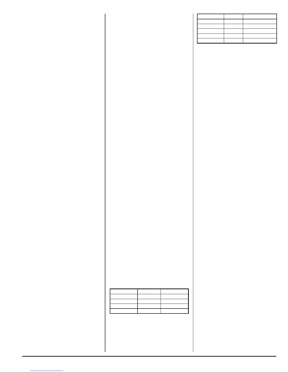
Model Crystal Formula
CA137-28 36.000 X = (RF-IF)/3
CA144-28 38.667 X = (RF-IF)/3
CA145-28 39.000 X = (RF-IF)/3
CA146-28 39.333 X = (RF-IF)/3
If you use fundamental crystals,
specify parallel resonance with 30
pf load capacitance, and use the
following table instead.
Model Crystal Formula
CA50-28 22.000 X = RF-IF
CA137-28 12.000 X = (RF-IF)/9
CA144-28 12.889 X = (RF-IF)/9
CA145-28 13.000 X = (RF-IF)/9
CA146-28 13.111 X = (RF-IF)/9
For purposes of determining crystal frequency on a broadband block
converter (any other than 10.7 IF),
substitute the frequency of the low
end of the band of interest. I.e., the
lowest frequency in the input band
is "RF" and the lowest output frequency is "IF". For example, for the
CA144-28, 144 MHz is the bottom
end of the input band and this is
translated to 28 MHz in the output
band; so those frequencies are used
for the formula.
Hamtronics stocks crystals for
the popular frequency schemes
(listed above), and we will be glad to
order any special crystals.
MOUNTING AND
INTERCONNECTIONS.
If the unit was not ordered with
optional case, the pc board is easily
mounted to a chassis or panel with
4-40 screws and threaded standoffs
using the holes provided in the four
corners. A mounting kit is available
(see rear of catalog).
The i-f output should be connected to the antenna input of the
hf receiver.
+13.6Vdc should be connected to
power pad E1.
ALIGNMENT AND TESTING.
The most difficult part of alignment is obtaining a stable test signal. If you don't have access to a vhf
signal generator, it is possible to
use a strong signal on the air.
à A tuning tool of the proper
type must be used to avoid cracking
the slugs in the coils. This is a
.060" square slot type tool. The
slugs are teflon coated; so they turn
easily. However, if a loosely fitting
tool or a tool only partially inserted
in the slot is allowed to slip in the
slot, the sideways force cracks the
powdered iron slug. Should this
happen, the slug must be drilled out
and replaced. Variable capacitor
C15 is adjusted with an insulated
tool with a small metal (slot type) bit
in the end. (See A2 and A28 Tuning
Tools in catalog.)
Page 3
©1995 Hamtronics, Inc.; Hilton NY; USA. All rights reserved. Hamtronics is a registered trademark. Revised: 2/1/00 - Page 3 -
a. Connect a source of +13.6Vdc
to E1.
b. Adjust slugs in all coils to the
center of their tuning ranges (half
inserted in windings). If you just
finished building a kit, turn rotor on
variable capacitor C15 90° either
way to center it.
c. Connect signal source to J1,
and connect J2 to receiver used as
an i-f.
d. Connect dc voltmeter to TP1.
e. Adjust oscillator coil L6 for a
peak (about 1 to 2 Vdc). Note that
oscillation may stop when tuning far
off peak on either side.
Note that a special procedure is
used for oscillator adjustment for
the six meter converter. See notes
at end of parts list.
f. With a moderately strong signal applied to the converter, tune in
the signal on the receiver.
g. Alternately adjust multiplier
coils L7 & L8, rf coils L1, L2, and L3,
and IF coil L4 for maximum response. Repeat adjustment to work
out any interactions between coils.
Reduce input signal to a fairly low
level for final adjustment. There
may be some benefit to readjusting
input coil L1 slightly for best noise
figure, which you can do by ear by
tuning for best quieting on a weak
signal.
Note: In rare cases, a spurious
oscillation may occur if the oscillator or multiplier stages are mistuned. When the unit is properly
tuned, oscillation will stop. Also
note that it is ok for tuning slugs to
extend above the top of the coils,
provided they are not too loose.
h. If a frequency counter is
available, connect it to TP1 and adjust variable capacitor C15 for
proper oscillator frequency. If counter is not available or if preferred,
adjust C15 for "on channel" reception.
Note: If crystal cannot quite be
adjusted to frequency, C28 can be
changed to a slightly higher or lower
value to extend the pulling range of
C15.
The final sensitivity of the converter should be about 0.1 to 0.2 uV
after tuning, assuming an i-f receiver of good sensitivity is used
with the converter.
OPERATION.
Operation is so simple, it is
hardly necessary to describe it.
However, some explanation of the
way broadband converters operate
may be helpful to you if you have not
used one before.
The converter operates by heterodyning (mixing) an entire block of
frequencies down to a new band of
frequencies which your receiver is
already capable of hearing. It does
this by mixing an oscillator/multiplier signal with the incoming signals to produce the sum
or difference of the two frequencies.
Thus, all the frequencies in the
incoming band are converted to new
frequencies a set value away from
the original frequencies. All the
frequencies still have the same relationship to each other in the new
spectrum.
As an example, use the CA14428 Converter frequency scheme. To
listen to 144.000 MHz, you would
tune your receiver to 28.000 MHz.
To hear 144.100 MHz, tune to
28.100; to hear 144.105, tune to
28.105, etc.
TROUBLESHOOTING.
If some coils do not peak within
the range of slug adjustment, as
may happen if the converter is modified for use on a different frequency
range, an adjustment in the value of
the capacitor in the tuned circuit
may be necessary. However, be
careful not to tune to an image frequency or tune the multiplier to the
wrong multiple of the oscillator frequency. If the slug is fully inserted
in the winding, more capacitance is
required. If the slug is all the way
out of the coil, less capacitance is
required. The value should be
changed by only about 5% at a time,
since that is about the tuning range
of the coil.
The usual troubleshooting techniques of checking dc voltages at
transistor elements and tracing oscillator injection signals with an rf
probe and voltmeter are appropriate
for this converter. A dc voltage
chart is given to indicate typical
voltages measured on a good converter; although voltages may vary
widely from unit to unit without
necessarily indicating a problem.
Also, measurements taken at points
with rf applied will depend on the
type of meter used and how it reacts
to rf.
Current drain is typically about
30mA; this is a very good indication
of any problems on the B+ line.
If no voltage is measured at TP1,
the emitter of the multiplier stage,
that is an indication that the rf level
from the oscillator is too low to drive
the base of the transistor into conduction.
Probably the most common trouble, based on our experience, is the
interchange of components, bad solder joints, and solder splashes. The
next most common trouble is blown
transistors due to reverse polarity or
transients on the B+ line. Any relay
coils connected across the B+ line
should have a reverse diode connected directly across the relay coil
to absorb the reverse transient produced when the relay is unkeyed.
Remember, if you encounter any
difficulties in initial test, that it is
easy to install parts in the wrong
place. Don't take anything for
granted. Double check everything
in the event of trouble.
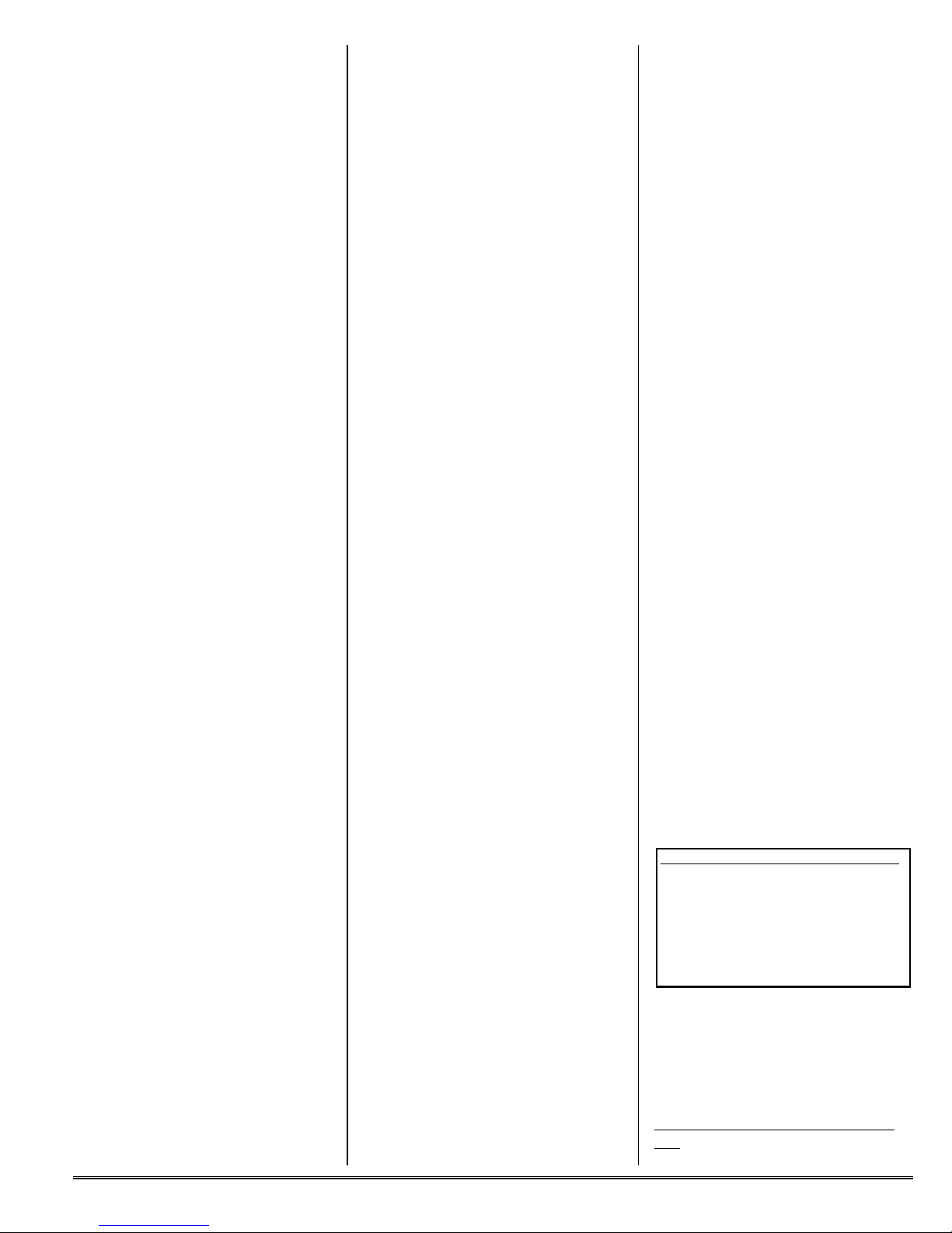
Typical Dc Voltages.
Following are positive dc voltages
with respect to ground, measured
with an fet voltmeter on a sample
unit operating on 13.6Vdc. While
readings can vary widely without
necessarily indicating trouble, these
readings can be used in conjunction
with an organized troubleshooting
plan to help isolate the trouble.
XSTR E(S) B(G1) G2 C(D)
Q1 0.5 0 6 12
Q2 3 0 - 13.6
Q3 2.5 3 - 9.1
Q3* 2.3 3 - 9.1
Q4 1.3 0 - 13.6
Q4* 0 0 - 13.6
* Crystal pulled out or oscillator signal otherwise absent.
PARTS LIST FOR
COMPONENTS COMMON TO
ALL MODELS.
(See next page for values which vary
with frequency range.)
Ref Desig Value (marking)
Page 4
©1995 Hamtronics, Inc.; Hilton NY; USA. All rights reserved. Hamtronics is a registered trademark. Revised: 2/1/00 - Page 4 -
C12 4.7 µf electrolytic
Q2 2N5486
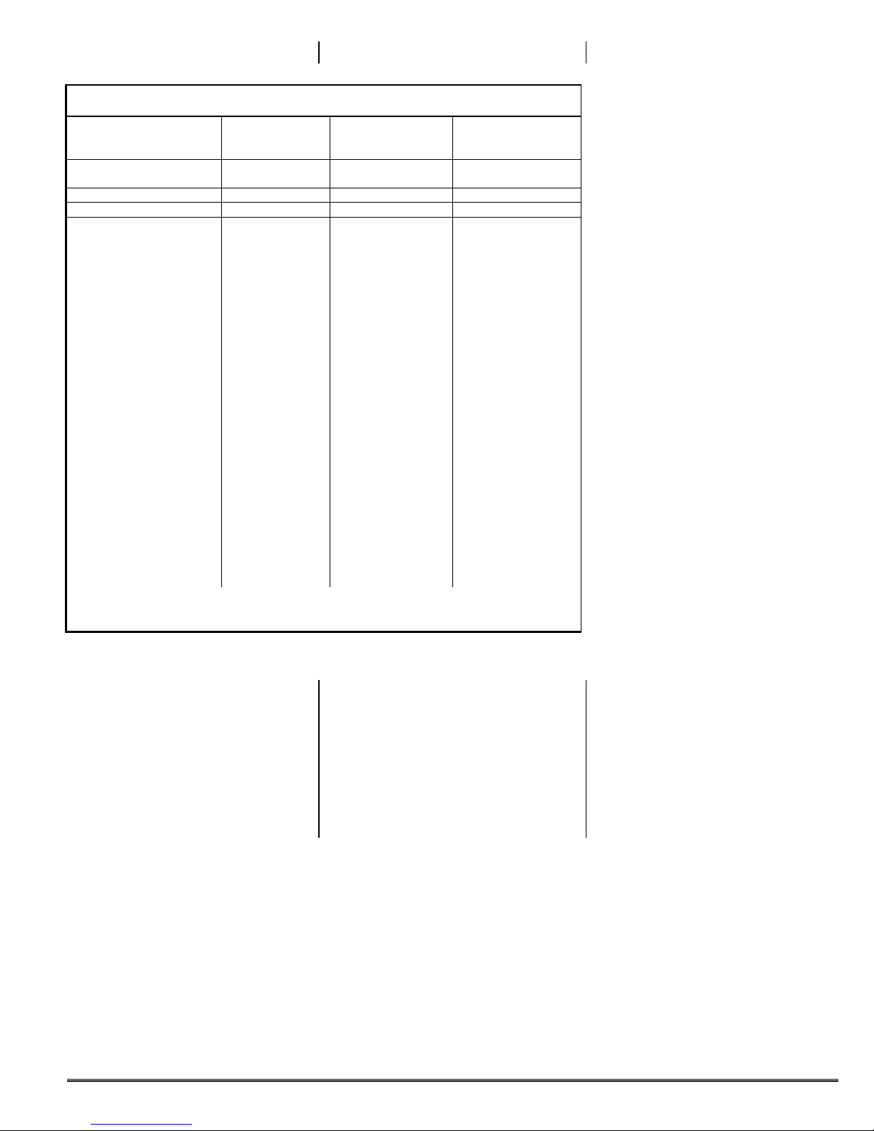
PARTS LIST FOR FREQUENCY-DEPENDENT COMPONENTS.
MODEL ⇒ CA50-28 CA137-28 CA144-28
INPUT RANGE (MHz) ⇒ 50-52 136-138 144-146 or 145-147
OUTPUT ⇒ 28-30 28-30 28-30
REF DESIG. ⇓ (Note 1)
C1 15 22 18
C2-C4 .001uf (note 2) 220 220
C5 39 2 1
C6 1 0.5 0.5
C7 39 18 15
C8 2 0.5 0.5
C9 .001uf (note 2) .001uf (note 2) .001uf (note 2)
C10 .0047 uf .001uf (note 2) .001uf (note 2)
C11 .001uf (note 2) 220 220
C13 62 62 62
C14 220 220 220
C18 .01 uf .001uf (note 2) .001uf (note 2)
C20 150 110 110
C21 not used 220 220
C22 .01 uf 220 220
C23 not used 10 8
C24 jumper 0.5 0.5
C25 not used 39 33
C27 220 62 62
L1 11-1/2T brn 2-1/2T red 2-1/2T red
L2 8-1/2S gry 6-1/2T blu 6-1/2T blu
L3 8-1/2S gry 2-1/2T red 2-1/2T red
L4 14-1/2T yel 14-1/2T yel 14-1/2T yel
L5 jumper jumper jumper
L6 10-1/2T blk 6-1/2T blu 6-1/2T blu
L7 not used 6-1/2T blu 6-1/2T blu
L8 not used 2-1/2T red 2-1/2T red
CA145-28
CA146-28
or 146-148
R11 470Ω
(See prior page for values common to all models.)
C15 30 pf variable capacitor
(green)
C16-C17 150 pf (151)
C19 .001 µf
C26 10 pf (under board)
C28 33 pf (under board)
J1, J2 See "Construction" text
L1-L8 (see next page)
Q1 3SK122
Q3, Q4 2N3904
R1, R2 100K
R3 180Ω
R4 470Ω
R5, R6 not used
R7 2.2K
R8 270Ω
R9 10K
R10 22K
R12 270Ω
R13 3.3K
R14 180Ω
R15 1.2K (under board)
Y1 Crystal (see chart on p.2)
Z1 Ferrite bead
Page 5

©1995 Hamtronics, Inc.; Hilton NY; USA. All rights reserved. Hamtronics is a registered trademark. Revised: 2/1/00 - Page 5 -
NOTES:
1. For model CA50-28, the multiplier stage is not used. Therefore, the following changes are made in pc
board wiring for this model only:
These parts are not used on this model: R13, Q4, C21, R14, L7, C23, C24, C25, and L8.
A jumper should be installed in place of Q4 base-collector. A second jumper should be installed in place
of C24. This effectively connects the junction of L6/C20 to C8. When wiring is finished, check the circuit
on the pc board to assure yourself that there is a complete circuit bypassing the usual multiplier stage.
A 10K resistor (R16) should be soldered to the pad normally used for the hot lead of L8. The resistor
should stand up on the pc board vertically, and the top lead should be trimmed to 1/8 inch to be used as a
test point.
To peak oscillator coil L6, it is necessary to use an rf probe and voltmeter or an oscilloscope. Connect
probe to the top of test point resistor R16, and peak L6 as otherwise stated in step (e.) of alignment instructions.
2. .001µF capacitor may be marked "102", "1nM", or "1nK".
Page 6
©1995 Hamtronics, Inc.; Hilton NY; USA. All rights reserved. Hamtronics is a registered trademark. Revised: 2/1/00 - Page 6 -
Page 7
©1995 Hamtronics, Inc.; Hilton NY; USA. All rights reserved. Hamtronics is a registered trademark. Revised: 2/1/00 - Page 7 -
 Loading...