

Page 1

READ AND SAVE THESE INSTRUCTIONS
FAN RATING AC 120V. 60Hz
UL LISTED MODEL : AC-552
MODEL# Y52YH5-06
CEILING FAN INSTALLATION AND
OPERATION INSTRUCTION
Page 2
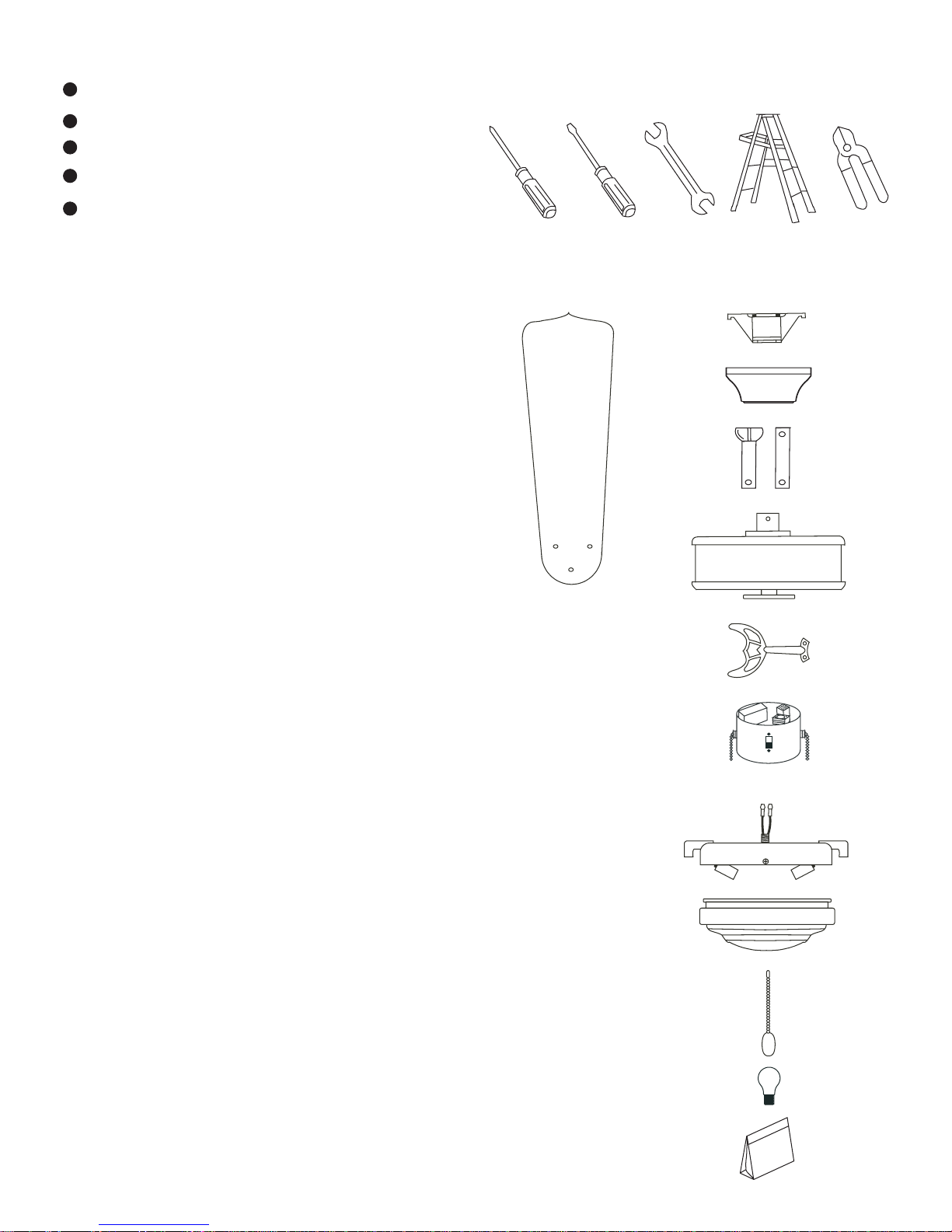
2. PACKAGE CONTENTS
U
npack your fan and check the contents.
Y
ou should have the following items;
a
. Fan blades (5)
b
. Hanger bracket
c
. Canopy
d
. Ball/downrod assembly (1)
& extra downrod (1)
e
. Fan motor assembly
f
. Set of blade brackets (5)
g
. Switch housing
h
. Light kit
i
. Glass shade
j
. Pull chain and fob (2)
k
. 60 Watt medium base bulbs (2)
l
. Package hardware
1) Mounting hardware :
wire nuts(3)
2) Blade attachment hardware:
screws(16)
3) Balance Kit
Philips screw driver
Blade screw driver
11 mm wrench
Step ladder
Wire cutters
1
1
. TOOLS AND MATERIALS
REQUIRED
a
b
c
d
e
f
g
h
i
j
l
k
Page 3

1
. To reduce the risk of electric shock,
insure electricity has been turned off
at the circuit breaker or fuse box
before beginning.
2
. All wiring must be in accordance with
the National Electrical Code and local
electrical codes. Electrical installation
should be performed by a qualified
licensed electrician.
3
. WARNING: To reduce the risk of
electrical shock and fire, do not use
this fan with any solid-state fan speed
control device.
4
. WARNING: To reduce the risk of
personal injury, use only the two steel
screws (and lock washers) provided
with the outlet box for mounting to
the outlet box. Most outlet boxes
commonly used for the support of
lighting fixtures are not acceptable for
fan support and may need to be
replaced, consult a qualified electrician
if in doubt.
5
. The outlet box and support structure
must be securely mounted and
capable of reliably supporting a
minimum of 50 pounds. Use only CUL
Listed outlet boxes marked "FOR FAN
SUPPORT".
6
. The fan must be mounted with a
minimum of 7 feet clearance from the
trailing edge of the blades to the floor.
7. Do not operate reversing switch whi
le
fan blades are in motion. Fan must b
e
turned off and blades stopped befo
re
reversing blade direction.
8. Avoid placing objects in the path of th
e
blades.
9. To avoid personal injury or damage
to
the fan and other items, be cautiou
s
when working around or cleaning th
e
fan.
10. Do not use water or detergents whe
n
cleaning the fan or fan blades. A d
ry
dust cloth or lightly dampened clo
th
will be suitable for most cleaning.
11. After marking electrical connection
s,
spliced conductors should be turne
d
upward and pushed carefully up in
to
outlet box. The wires should be sprea
d
apart with the grounded conduct
or
and the equipment-groundin
g
conductor on one side of the outl
et
box.
12. Electrical diagrams are reference on
ly.
Light kit that are not packed with th
e
fan must be CUL Listed and marke
d
suitable for use with the model fan yo
u
are installing. Switches must be CU
L
General Use Switches. Refer to th
e
Instructions packaged with the lig
ht
kits and switches for proper assembly
.
2
3. SAFETY RULES
WARNING
TO REDUCE THE RISK OF FIRE,
ELECTRIC SHOCK OR PERSONAL
INJURY, MOUNT FAN TO OUTLET BOX
MARKED "ACCEPTABLE FOR FAN
SUPPORT".
WARNING
TO REDUCE THE RISK OF PERSONAL
INJURY, DO NOT BEND THE BLADE
BRACKETS (ALSO REFERRED TO AS
FLANGES) DURING ASSEMBLY OR
AFTER INSTALLATION. DO NOT
INSERT OBJECTS IN THE PATH OF THE
BLADES.
Page 4

4
. MOUNTING OPTIONS
If there isn't an existing CUL listed
mounting box, then read the following
instructions. Disconnect the power by
removing fuses or turning off circuit
breakers.
Secure the outlet box directly to the
building structure. Use appropriate
fasteners and building materials. The
outlet box and its support must be able to
fully support the moving weight of the fan
(at least 50 lbs). Do not use plastic outlet
boxes.
Figures 1,2 and 3 are examples of different
ways to mount the outlet box.
Note: You may need a longer downrod to
maintain proper blade clearance when
installing on a steep, sloped ceiling. (Fig. 3)
Outlet box
Provide strong
support
Recessed
outlet box
Ceiling
mounting
plate
Outlet box
Figure 1
Figure 3
Figure 4
Outlet box
Figure 2
3
Angled ceiling
maximum
20o angle
Page 5

R
EMEMBER to turn off the power. Follow
t
he steps below to hang your fan properly:
S
tep 1. Pass the 120-volt supply wires
t
hrough the center hole in the ceiling
h
anger bracket as shown in Fig. 5.
S
tep 2. Secure the hanger bracket to the
c
eiling outlet box with the screws and
w
ashers provided with your outlet box.
S
tep 3. Remove the hanger pin, lock pin
a
nd set screws from the top of the motor
a
ssembly.
S
tep 4. Route wires exiting from the top
o
f the fan motor through the canopy and
t
hen through the ball / downrod. (Fig. 6)
S
tep 5. Align the holes at the bottom of
t
he downrod with the holes in the collar
o
n top of the motor housing (Fig.6).
C
arefully insert the hanger pin through
t
he holes in the collar and downrod. Be
c
areful not to jam the pin against the
w
iring inside the downrod. Insert the
l
ocking pin through the hole near the end
o
f the hanger pin until it snaps into its
l
ocked position. (Fig. 6)
S
tep 6. Tighten two set screws on top of
t
he fan motor firmly. (Fig. 6)
S
tep 7. Place the downrod ball into the
h
anger bracket socket. (Fig. 7)
C
HANGING THE DOWNROD (OPTIONAL)
N
OTE: Your fan comes with a 4" downrod
a
ttached to the hanger ball. In addition
y
ou have been provided with a 6"
d
ownrod to use if desired. If you choose
t
o use the 6" downrod, perform the
f
ollowing steps.
1
. Remove the hanger ball from the 4"
d
ownrod by loosening the set screw at
t
he top of the downrod which holds the
h
anger ball to the downrod.
2
. Slide the hanger ball down the
d
ownrod and remove the support pin.
3
. Insert the support pin in the holes at the
t
op of the 6" downrod and slide the
h
anger ball up the 6" downrod. Make sure
t
he support pin is properly seated in the
g
rooves in the top of the hanger ball.
4
. Tighten the set screw firmly.
5. Hanging the Fan
4
Mounting screws
(supplied with
electrical box)
Hook
Hanger
bracket
UL Listed
electrial
box
Figure 5
Figure 6
Figure 7
120V Wires
Washers
Registration slot
Downrod
Canopy
Set screws
Hitch pin
Lock pin
Page 6

5
6
. MAKE THE ELECTRIC
CONNECTIONS
R
emember to disconnect the power.
F
ollow the steps below to connect the fan
t
o your household wiring. Use the wire
c
onnecting nuts supplied with your fan.
S
ecure the connectors with electrical tape.
M
ake sure there are no loose strands or
c
onnections.
S
tep 1 Connect the fan supply (black) wire
a
nd light supply (blue) wire to the black
h
ousehold supply wire as shown in Figure 8.
S
tep 2. Connect the neutral fan (white)
w
ire to the white neutral household wire.
S
tep 3 Connect the fan ground wire
(
green) to the household ground wire.
S
tep 4 After connecting the wires, spread
t
hem apart so that the green and white
w
ires are on one side of the outlet box and
t
he black and the blue wires are on the
o
ther side.
S
tep 5 Turn the connecting nuts upward
a
nd push the wiring into the outlet box.
F
igures 9 and 10 illustrate the wiring
c
onnections for optional wall control. (The
w
ire color out of wall control may vary, see
w
all control's installation manual for
c
orrect wire connections.)
N
OTE: LIGHT KITS ARE AVAILABLE AT YOU
S
AVOY HOUSE RETAILER. THE FAN IS
A
LREADY WIRED TO SUPPORT THE LIGHT
K
IT OPTION.
W
ARNING: TO REDUCE THE RISK OF FIRE,
E
LECTRIC SHOCK, OR OTHER PERSONAL
I
NJURY. MOUNT FAN ONLY ON AN OUTLET
B
OX OR SUPPORTING SYSTEM MARKED
"
ACCEPTABLE FOR FAN SUPPORT".
Figure 8
Figure 9
BLK
WH
BLUE
BLK
WH
GRN
WIRING
BOX
WIRING
BOX
GROUND TO
MOUNTING
BRACKET
OR DOWNROD
GROUND TO
MOUNTING
BRACKET
OR DOWNROD
BLUE
BLK
WH
WH
FAN
LIGHT
POWER LINES 120V
POWER LINES 120V
BLK
WH
BLUE
BLK
WH
FAN
LIGHT
BLK
BLUE
WH
WH
LIGHT
SWITCH
GREEN GROUND
GREEN GROUND
Figure 10
GROUND TO
MOUNTING
BRACKET
OR DOWNROD
POWER LINES 120V
GREEN
GROUND
WIRING
BOX
BLK
WH
BLUE
BLK
WH
FAN
LIGHT
WH
WH
BLUE
BLK
LIGHT
FAN
Page 7

6
7
. FINISHING THE
INSTALLATION
S
tep 1. Slide the canopy up to the
c
eiling and over the two screws on
h
anger bracket. Rotate canopy clockwise
u
ntil tight.
N
ote: adjust the canopy screws as
n
eeded until the canopy is snug. (Fig. 11)
Figure 11
Outlet box
Hanger
bracket
Canopy
Screws
8
. ATTACHING THE FAN
BLADES
S
tep 1 Attach the blades to the blade
b
rackets using the screws and rubber
w
ashers provided as shown in Figure 12.
S
tart a screw into the bracket, but do not
t
ighten. Repeat for the other 2 screws and
w
ashers.
S
tep 2 Tighten each screw securely
s
tarting with the center screw. Make sure
t
he blade is straight.
S
tep 3 Fasten the blade assemblies to the
m
otor by insert the tab from the blade
b
rackets to the slot in the bottom motor
h
ousing, then tighten the two screws and
w
ashers already installed in the blade
b
rackets (Figure 13).
S
tep 4 Install an optional light kit if
you wish. Follow the instructions
included with the kit.
Figure 12
Figure 13
Blade
Blade bracket
Screws
Rubber
washers
Motor
Blade
bracket
Slot
Tab
Page 8

7
Figure 14
Figure 15
9
. INSTALLING THE LIGHT
KIT
N
OTE: Before starting installation,
d
isconnect the power by turning off the
c
ircuit breaker or removing the fuse at
f
use box.
T
urning power off using the fan switch is
n
ot sufficient to prevent electric shock.
1
. Remove the plug from the switch
h
ousing (Fig. 17), attach the light kit to the
s
witch housing by feeding the light kit
w
ires (black and white) through the hole
o
f switch housing and then screw it onto
t
he switch housing by nut & lock washer
p
rovided. Be sure it is tight enough to
p
revent light kit from vibrating loose.
N
OTE: For easy pull chain installation, be
s
ure that the location of the 3 speed
s
witch on the switch housing and the pull
c
hain holder on the light kit are in suitable
l
ocations as shown on Fig. 14 and 15.
2
. Locate two single white and blue wires
i
n the switch housing labeled FOR LIGHT.
3
. Make the polarized plug connections:
- White to white
- Blue to black
4
. While holding the light kit assembly
u
nder your fan, snap together the wire
c
onnection plugs .
5
. Carefully push all wires back into the
s
witch housing, then install the light kit
a
ssembly onto the mounting plate with 3
s
crews provided. Be sure to tighten all
s
crews. (Fig. 15)
6
. Pass the two pull chains on the switch
h
ousing through the chain holders
l
ocated on the light kit, install the fobs to
t
he pull chains. (Fig. 15)
7
. Install two 60 watt (max.) bulbs
(
included) and glass shade with four
t
humb screws, do not over tighten.
8
. Restore power and your light kit is ready
f
or operation.
9
. If the light kit does not work, turn off the
e
lectricity and lower either canopy on
y
our ceiling fan to make sure the blue wire
i
s connected to the black household wire.
Switch housing
Light kit
Nut
Lock washer
Pull chain
Plug
Pull chain holder
Mounting plate
Connection plug
Screws
Thumb screws
Light kit assembly
Glass shade
Bulbs
Pull chain holder
Page 9

8
10. OPERATING YOUR FAN
N
OTE: Wait for fan to stop before
c
hanging the setting of the slide
s
witch.
T
urn on the power and check the
o
peration of your fan. The pull chain
c
ontrols the fan speed as follows: 1
p
ull- High, 2 pulls-Medium, 3 pulls-
L
ow, and 4 pulls-Off.
S
peed settings for warm or cool
w
eather depend on factors such as the
r
oom size, ceiling height, number of
f
ans and so on.
T
he slide switch controls directions:
f
orward (switch down) or reverse
(
switch up)
W
arm weather - (Forward) A
d
ownward airflow creates a cooling
e
ffect as shown in Fig. 16. This allows
y
ou to set your air conditioner on a
w
armer setting without affecting your
c
omfort.
C
ool weather - (Reverse) An upward
a
irflow moves warm air off the ceiling
a
rea as shown in Fig. 17. This allows
y
ou to set your heating unit on a
c
ooler setting without affecting your
c
omfort.
Figure 16
Figure 17
Page 10

9
P
roblem
F
an will not start.
F
an sounds
n
oisy.
Solution
1. Check circuit fuses or breakers.
2. Check line wire connections to the fan and switch wire connection
s
in the switch housing.
CAUTION: Make sure main power is off.
1. Make sure all motor housing screws are snug.
2. Make sure the screws that attach the fan blade bracket to the mot
or
hub is tight.
3. Make sure wire nut connections are not rubbing against each oth
er
or the interior wall of the switch housing.
CAUTION: Make sure main power is off.
4. Allow a 24-hour "breaking-in" period. Most noise associated with
a
new fan disappear during this time.
5. If using an optional light kit, make sure the screws securing th
e
glassware are tight. Check that light bulb is also secure.
6. Some fan motors are sensitive to signals from solid-state variab
le
speed controls. If you have installed this type of control, choose an
d
install another type of control.
7. Make sure the upper canopy is a short distance from the ceiling.
It
should not touch the ceiling.
1
1. TROUBLESHOOTING
Page 11

10
These are approximate measures. They do not include Amps and Wattage used by th
e
light kit.
12. SPECIFICATIONS
Fan Size
Speed Volts Amps Watts RPM CFM N.W. G.W. C.F.
52"
120
120
120
0,20
0,35
0,49
7
25
56
57
111
163
1025
3500
5400
9,7
kgs
11.8
kgs
1,81
Low
Medium
High
 Loading...