

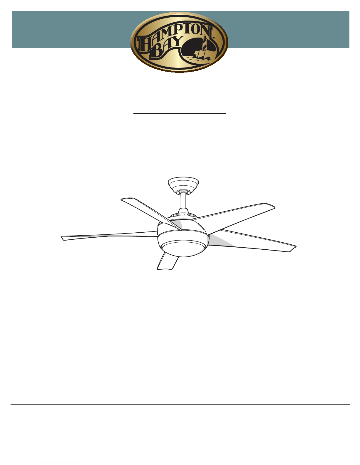
HAMPTON BAY 26613, 26623, WINDWARD IV 26613, WINDWARD IV 26623 Use And Care Manual
THANK YOU
We appreciate the trust and confidence you have placed in Hampton Bay through the purchase of this ceiling fan. We strive to continually create
quality products designed to enhance your home. Visit us online to see our full line of products available for your home improvement needs.
Thank you for choosing Hampton Bay!
Item # 458-301, 458-633
Model # 26613, 26623
UL Model # 52-WWDIV
USE AND CARE GUIDE
WINDWARD IV 52-INCH CEILING FAN
Questions, problems, missing parts? Before returning to the store call
Hampton Bay Customer Service
8 a.m. - 6 p.m., EST, Monday-Friday
1-877-527-0313
HAMPTONBAY.COM
2
Table of Contents .......................................................... 2
Safety Information ......................................................... 2
Warranty ......................................................................... 3
Pre-Installation .............................................................. 3
Installation ..................................................................... 6
Assembly ....................................................................... 7
Operation .................................................................... 12
Care and Cleaning ...................................................... 13
Troubleshooting .......................................................... 14
Safety Information
1. To reduce the risk of electric shock, ensure the
electricity has been turned off at the circuit breaker or
fuse box before you begin.
2. All wiring must be in accordance with the National
Electrical Code ANSI/NFPA 70-1999 and local electrical
codes. Electrical installation should be performed by a
qualied licensed electrician.
3. The outlet box and support structure must be securely
mounted and capable of reliably supporting a minimum
of 35 lbs. (16 kg). Use only UL-listed outlet boxes marked
“For Fan Support.”
4. The fan must be mounted with a minimum of 7 ft (2 m)
clearance from the trailing edge of the blades to the
oor.
5. Do not operate the reversing switch while the fan blades
are in motion. You must turn the fan off and stop the
blades before you reverse the blade direction.
6. Do not place objects in the path of the blades.
7. To avoid personal injury or damage to the fan and other
items, use caution when working around or cleaning the
fan.
8. Electrical diagrams are for reference only. Light kits that
are not packed with the fan must be UL-listed and
marked suitable for use with the model fan you are
installing. Switches must be UL General Use Switches.
Refer to the instructions packaged with the light kits and
switches for proper assembly.
9. After making electrical connections, spliced conductors
should be turned upward and pushed carefully up into
outlet box. The wires should be spread apart with the
grounded conductor and the equipment-grounding
conductor on one side of the outlet box.
10. All setscrews must be checked and retightened where
necessary before installation.
WARNING: To reduce the risk of personal injury,
do not bend the blade brackets (also referred to as
anges) during assembly or after installation. Do not
insert objects in the path of the blades.
WARNING: To reduce the risk of re or electric
shock, do not use this fan with any solid-state speed
control device.
WARNING: To avoid possible electrical shock,
turn the electricity off at the main fuse box before
wiring. If you feel you do not have enough electrical
wiring knowledge or experience, contact a licensed
electrician.
WARNING: Electrical diagrams are for reference
only. Optional use of any light kit must be
UL-listed
and marked suitable for use with this fan.
CAUTION: To reduce the risk of personal injury,
use only the screws provided with the outlet box.
WARNING: To reduce the risk of re or electric
shock, this fan should only be used with fan speed
control part no. Fan28R-240W, manufactured by
Chai Wei Electric Co., LTD.
Table of Contents
MOC.YABNOTPMAH
3
.ecnatsissa rehtruf rof 3130-725-778-1 tcatnoc esaelP
The supplier warrants the fan motor to be free from defects in workmanship and material present at time of shipment from the factory for a
period of lifetime after the date of purchase by the original purchaser. The supplier also warrants that all other fan parts, excluding any
glass or acrylic blades, to be free from defects in workmanship and material at the time of shipment from the factory for a period of two
years after the date of purchase by the original purchaser. We agree to correct such defects without charge or at our option replace with a
comparable or superior model if the product is returned. To obtain warranty service, you must present a copy of the receipt as proof of
purchase. All costs of removing and reinstalling the product are your responsibility. Damage to any part such as by accident or misuse or
improper installation or by afxing any accessories, is not covered by this warranty. Because of varying climatic conditions this warranty
does not cover any changes in brass nish, including rusting, pitting, corroding, t
arnishing, or peeling. Brass nishes of this type give their
longest useful life when protected from varying weather conditions. A certain amount of “wobble” is normal and should not be considered a
defect. Servicing performed by unauthorized persons shall render the warranty invalid. There is no other express warranty. Hampton Bay
hereby disclaims any and all warranties, including but not limited to those of merchantability and tness for a particular purpose to the
extent permitted by law. The duration of any implied warranty which cannot be disclaimed is limited to the time period as specied in the
express warranty. Some states do not allow a limitation on how long an implied warranty lasts, so the above limitation may not apply to you.
The retailer shall not be liable for incidental, consequential, or special damages arising out of or in connection with product use or
performance except as may otherwise be accorded by law. Some states do not allow the exclusion of incidental or consequential damages,
so the above exclusion or limitation may not apply to you. This warranty gives specic legal rights, and you may also have ot
her rights
which vary from state to state. This warranty supersedes all prior warranties. Shipping costs for any return of product as part of a claim on
the warranty must be paid by the customer.
Contact the Customer Service Team at 1-877-527-0313 or visit www.hamptonbay.com
Pre-Installation
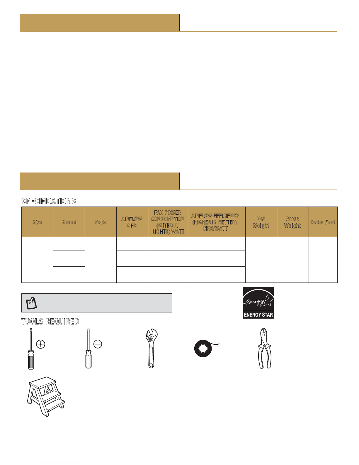
SPECIFICATIONS
Size Speed Volts
N
et
W
eight
G
ross
W
eight
C
ube Feet
52”
Low
120
20.2
lbs
(9.2kgs)
23.1lbs
(10.5kg)
1.7’
Medium
High
12
30
57
204
143
106
2448
4289
6057
NOTE: These are approximate measures. They do not
include the Amps and Wattage used by the light kit.
TOOLS REQUIRED
Phillips
screwdriver
Flat blade
screwdriver
Adjustable
wrench
Electrical
tape
Wire
cutter
Step ladder
Warranty
AIRFLOW
CFM
FAN POWER
CONSUMPTION
(WITHOUT
LIGHTS) WATT
AIRFLOW EFFICIENCY
(HIGHER IS BETTER)
CFM/WATT
4
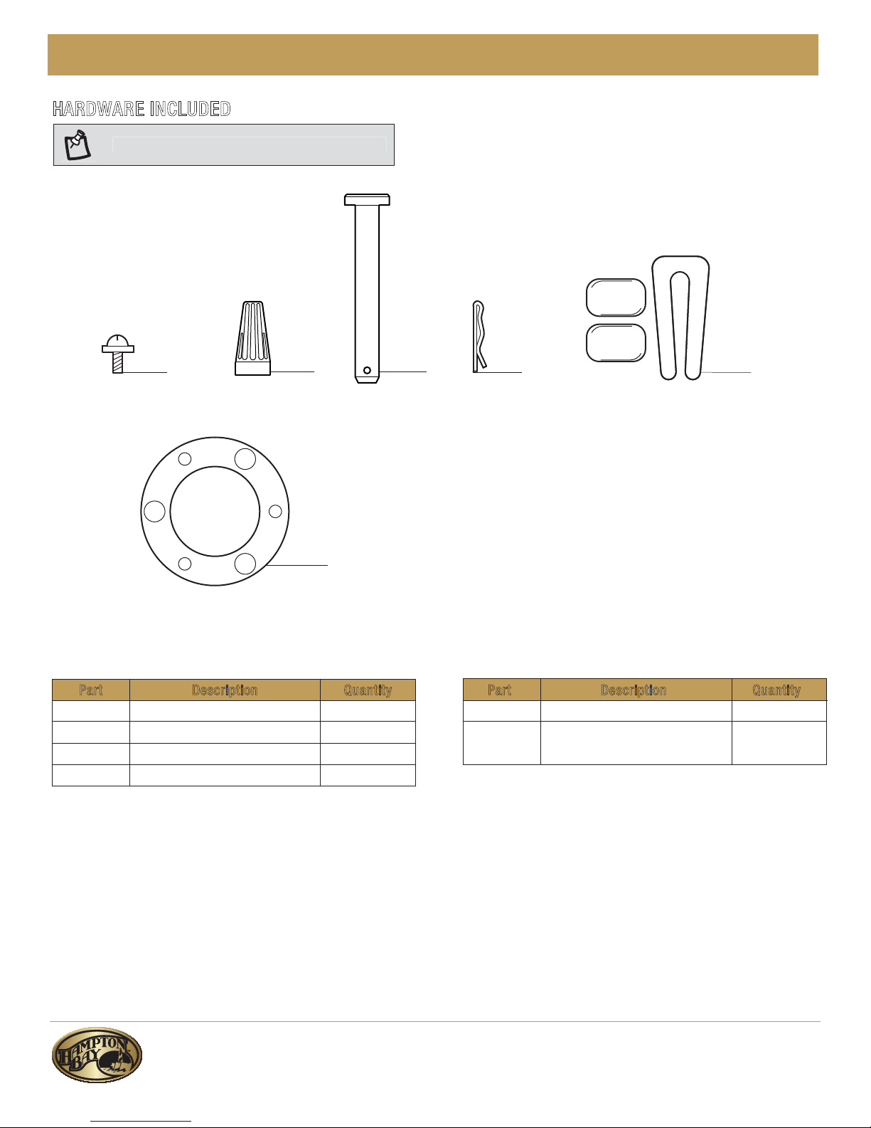
HARDWARE INCLUDED
NOTE: Hardware not shown to actual size.
Part Description Quantity
AA Blade attachment screw 16
BB Wire connecting nut
CC Hanger pin 1
DD Locking pin 1
P
art Description Quantity
EE Balancing kit 1
Close-to ceiling mount
hardware (rubber gasket)
1FF
AA
BB
CC
DD
EE
FF
Pre-Installation (continued)
3
MOC.YABNOTPMAH
5
.ecnatsissa rehtruf rof 3130-725-778-1 tcatnoc esaelP
Pre-Installation (continued)
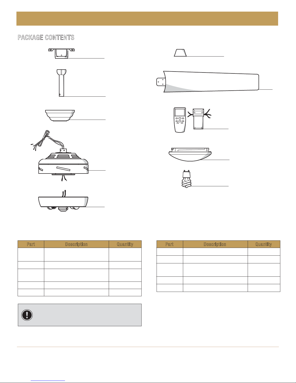
PACKAGE CONTENTS
Part Description Quantity
A Slide-on mounting bracket
(inside the canopy)
1
B Ball/downrod assembly 1
C Canopy with canopy ring
attached
1
D Fan-motor assembly 1
Light kit tter assembly
Light bulbs,13-Watt maximum
E 1
P
art Description Quantity
F Decorative motor collar cover 1
G Blade 5
H
J
I
Remote control/receiver (batteries
included)
1
Glass bowl 1
2
IMPORTANT: This product and/or components are
governed by one or more of the following U.S. Patents:
5,947,436; 5,988,580; 6,010,110; 6,046,416, 6,210,117 and
other patents pending.
Part Description Quantity
E
B
J
H
I
BB
G
F
D
A
C
B
6
Installation
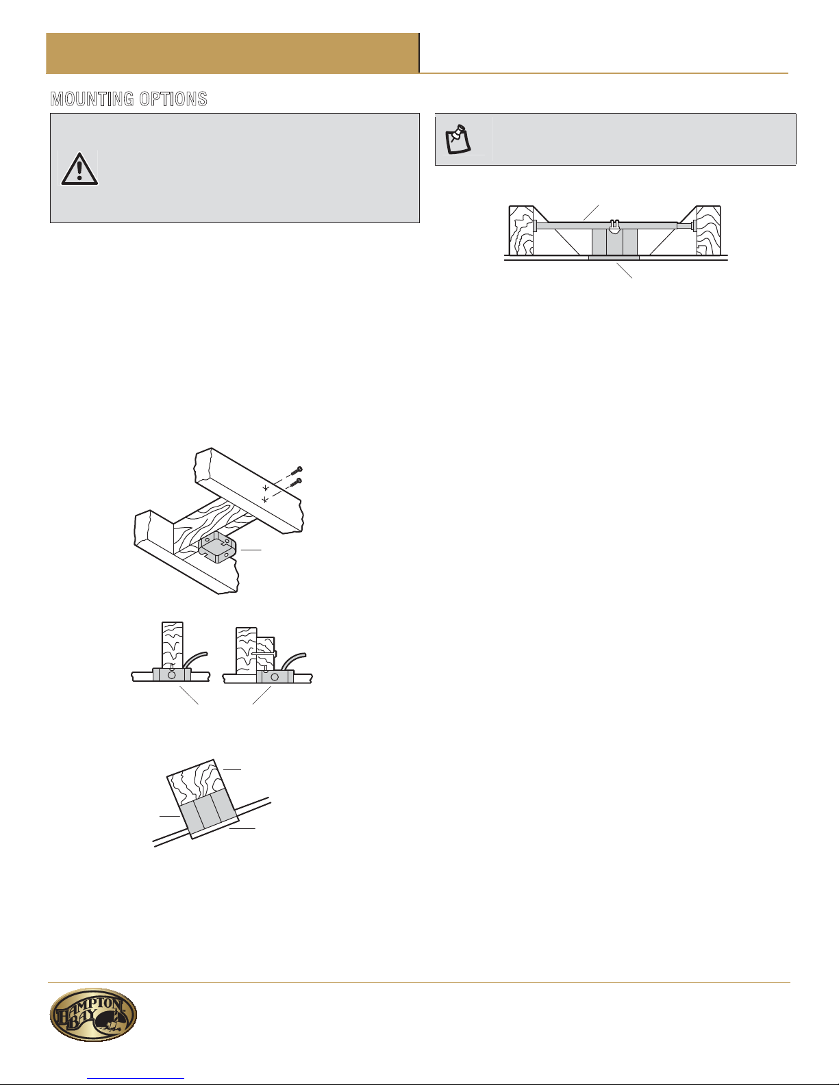
MOUNTING OPTIONS
WARNING: To reduce the risk of re, electric shock, or
personal injury, mount the fan to an outlet box marked
acceptable for fan support using the screws provided with the
outlet box. An outlet box commonly used for the support of
lighting xtures may not be acceptable for fan support and
may need to be replaced. If in doubt, consult a qualied
electrician.
If your ceiling fan does not have an existing UL-listed mounting
box, then install one using the following instructions:
Ƒ Disconnect the power by removing the fuses or turning
off the circuit breakers.
Ƒ Secure the outlet box directly to the building structure.
Use the appropriate fasteners and materials. The outlet
box and its bracing must be able to fully support the
weight of the moving fan (at least 35 lbs.). Do not use a
plastic outlet box.
The illustrations below show three different ways to mount the
outlet box.
If the canopy touches the downrod, then remove the decorative
canopy bottom cover, and turn the canopy 180° before attaching
the canopy to the mounting plate.
To hang your fan where there is an existing xture but no ceiling
joist, you may need an installation hanger bar as shown above
(available at any Home Depot store).
Outlet Box
Outlet Box
Provided Strong
Support
Ceiling Mounting
Plate
Recessed
Outlet Box
NOTE: You may need a longer downrod to maintain proper
blade clearance when installing on a steep, sloped ceiling.
The maximum angle allowable is 30° away from horizontal.
Outlet Box
Hanger Bar

motor housing (D).
motor housing (D).
motor housing (D).
(GG)
GG
Failure to properly install the locking pin
could result in the fan becoming loose and possibly
falling.

8
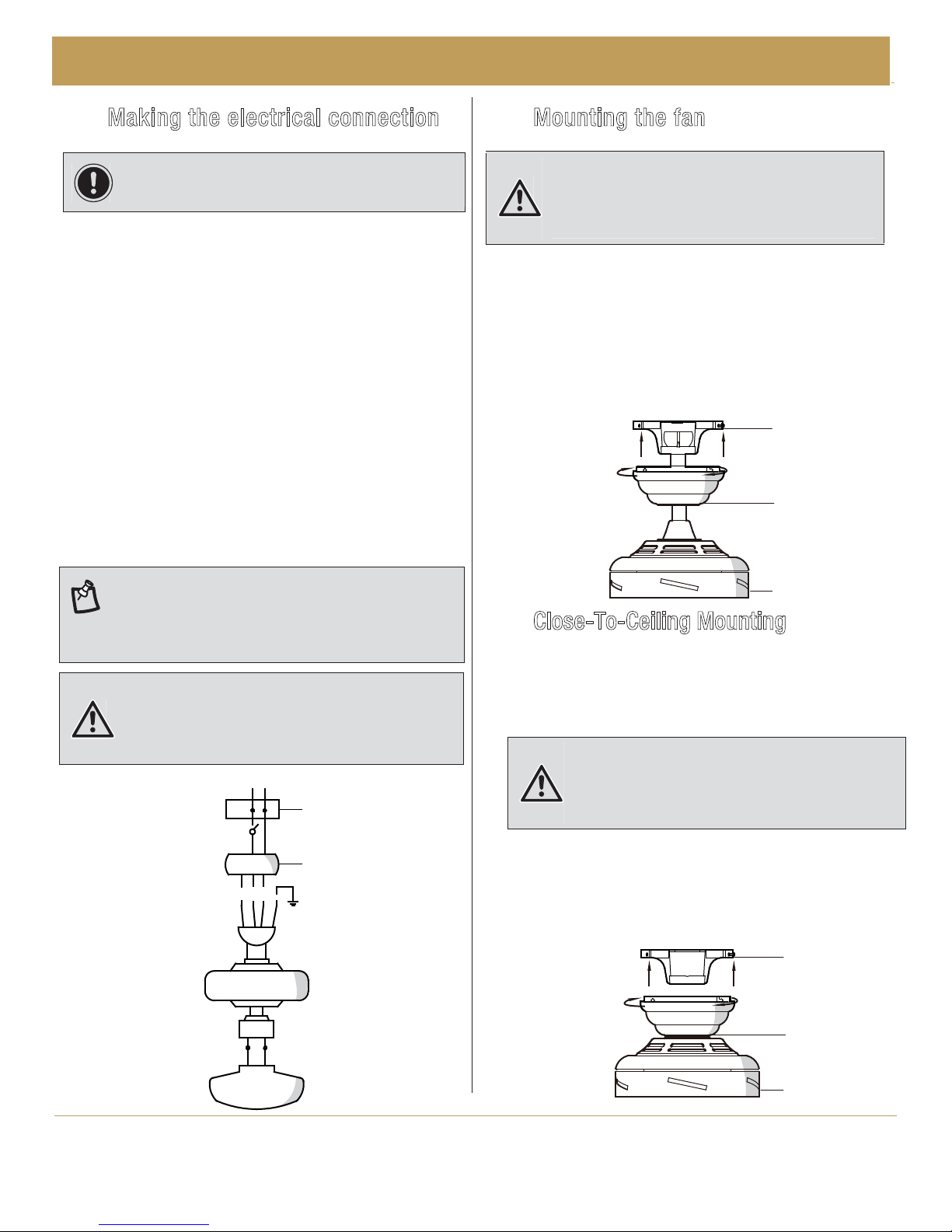
Assembly – Hanging the Fan
4
Attaching the fan to the electrical
b
ox
5
Hanging the fan
Ƒ Pass the 120-Volt supply wires through the center hole
in the mounting bracket (A).
Ƒ Install the ceiling mounting bracket on the outlet box by
sliding the mounting bracket (A) over the two screws
provided with the outlet box. If necessary, use leveling
washers (not included) between the mounting bracket
(A) and the outlet box. Note that the at side of the
mounting bracket (A) is toward the outlet box. When
using close-to-ceiling mounting, it is important that the
mounting bracket be level.
Ƒ Securely tighten the two mounting screws.
Ƒ Carefully lift the fan-motor assembly (D) up to the
mounting bracket (A).
Ƒ Seat the hanger ball portion of the ball/downrod assembly
(B) in the mounting bracket socket. Ensure that the tab on
the mounting bracket (A) socket is properly seated in the
groove in the hanger ball. If using close-to-ceiling
mounting, hang the fan on the hook provided by utilizing
one of the holes at the outer rim of the ceiling canopy.
WARNING: To reduce the risk of re, electric shock, or
other personal injury, mount the fan to an outlet box or
supporting system marked acceptable for fan support, and
use the mounting screws provided with the outlet box.
WARNING: The hook as shown is only to balance fan while
attaching wiring. Failure to hang as shown may result in the
hook breaking, causing the fan to fall. Hook must pass from
inside to outside of canopy.
A
Assembly -Close-To-Ceiling Mounting
Ƒ Remove the decorative canopy bottom cover (L) from the
canopy (C) by depressing the three studs.
Ƒ Remove three of the six screws and lock washers (every
other one) securing the motor collar to the top of the fan
motor housing.
Ƒ Place the rubber gasket (FF) over the remaining three
screws, route the wires exiting the top of the fan motor
through the canopy ring (make sure the slot openings are
on top), then proceed to place the ceiling canopy (C) over
the collar at the top of the motor.
Ƒ Align the mounting holes with the holes in the motor and
fasten, using the three screws and lock-washers removed
previously. Tighten the mounting screws securely.
L
C
C
D
FF
Ƒ Remove canopy ring from the canopy (C) by turning the
ring to the right until it unlocks.
ƑƑRemove the mounting bracket (A) from the canopy (C) by
loosening the four screws on the top of the canopy (C).
Remove the two non-slotted screws and loosen the
slotted screws.
1
Close-to-Ceiling Mounting
A
D
A
B
D
NOTE :
The frequencies on your receiver and remote control
have beet preset at the factory. Before installing the receiver,
make sure the dip switches on the receiver and remote control
are set to the same frequency. The dip switches on the remote
control are located inside the battery compartment.
MOC.YABNOTPMAH
9
.ecnatsissa rehtruf rof 3130-725-778-1 tcatnoc esaelP
Assembly – Hanging the Fan (continued)
6
Making the electrical connection
7
Mounting the fan
IMPORTANT: Use the wire connecting nuts supplied with
your fan. Secure the connectors with electrical tape and
ensure there are no loose strands or connections.
Ƒ Connect the ground conductor of the 120-Volt supply (this
may be a bare wire or a wire with green colored insulation)
to the green ground lead(s) (II) of the fan.
Ƒ Connect the fan motor white wire (LL) to the receiver (NN)
white wire (LL) using a wire nut.
Ƒ Connect the fan motor black wire (KK) to the receiver (NN)
black wire (KK) using a wire nut.
Ƒ Connect the fan motor blue wire (JJ) to the receiver (NN)
blue wire (JJ) using a wire nut.
Ƒ Connect the receiver (NN) red wire (OO) to the supply black
(hot) wire (KK) using a wire nut.
Ƒ Connect the receiver (NN) white wire (LL) to the supply white
wire (neutral) (LL) wire using a wire nut.
Ƒ After connecting the wires, spread them apart so that the
green (II) and white wires (LL) are one side of the outlet box
(MM) and the black wire (KK) is on the other side.
Ƒ Turn the wire connecting nuts upward and carefully push
the wiring into the outlet box (MM).
Ƒ Align the locking slots of the ceiling canopy (C) with the
two screws in the mounting bracket (A). Push up to engage
the slots, and turn clockwise to lock the canopy in place.
Ƒ Firmly tighten the two mounting screws.
Ƒ Install the remaining two mounting screws into the holes in
Ƒ Install the decorative canopy ring by aligning the ring's
slots with the screws in the canopy (C). Rotate the ring
counter-clockwise to lock in place.
the canopy (C) and tighten rmly.
WARNING: Each wire nut supplied with this fan is designed
to accept up to one 12-guage house wire and two wires from
WARNING: When using the standard ball/downrod
mounting, the tab in the ring at the bottom of the mounting
plate must rest in the groove of the hanger ball. Failure to
properly seat the tab in the groove could cause damage to
the wiring.
the fan. If you have larger than 12-guage house wiring or
more than one house wire to connect to the fan wiring,
consult an electrician for the proper size wire nuts to use.
Ƒ
Close-To-Ceiling Mounting
Carefully unhook the fan from the mounting bracket (A) and
align the locking slots of the ceiling canopy (C) with the two
screws in the mounting bracket (A). Push up to engage the
slots and turn clockwise to lock the canopy in place.
Immediately tighten the two mounting screws rmly.
Ƒ
Install the remaining two mounting screws into the holes in
the canopy (C) and tighten rmly.
Ƒ
Install the decorative canopy ring by aligning the ring's
slots with the screws in the canopy (C). Rotate the ring
counter-clockwise to lock it in place.
NN
KK
LL
OO
LL
KK
LL
JJ
II
JJ
KK
LL
LL
MM
D
C
A
D
C
A
The locking slots of the ceiling canopy are
provided only as an aid to mounting. Do not leave the fan
assembly unattended until all four canopy screws are
engaged and rmly tightened.
WARNING:
01
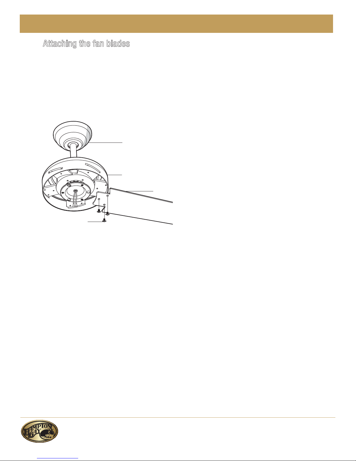
Assembly – Attaching the Fan Blades
8
Attaching the fan blades
ƑƑ Attach the blade (G) to the fan motor housing (D) by rst
inserting the blade (G) into the slot in the side of the fan
motor housing (D).
Start a screw (AA) into the bracket. Repeat for the two
remaining screws.
Ƒ Tighten each screw (AA) securely.
Ƒ Repeat these steps for the remaining blades (G).
G
AA
C
D
 Loading...