

HAMPTON BAY Windward II, Windward II 523 342, Windward II 523 127 Owner's Manual
523 342
523 127
Windward II
54
in Ceiling Fan
Owner’s Manual
Windward II
Ventilador de Techo de 1,37
m
Manual del Propietario
213 mm
The spot color is for reference proof only, please follow
pantone guide for actual color when printing.
This line is for die-cut position only
DO NOT PRINT IT!!!
Black Magenta Yellow Black PMS 465C PMS 5425C PMS 632C Die
Total Colors
Coating
Varnish
ADDITIONAL INFORMATION
V1.3
09-07-29
V0.0
17 Apr 09
V0.0
17 Apr 09
V0.0
17 Apr 09
V0.0
17 Apr 09
V0.0
17 Apr 09
V0.0
17 Apr 09
V0.0
17 Apr 09
V0.0
17 Apr 09
V0.0
17 Apr 09
V0.0
17 Apr 09
V0.0
17 Apr 09
V0.0
17 Apr 09
V0.0
17 Apr 09
V0.0
17 Apr 09
V0.0
17 Apr 09
1. UPC at 100% and without truncated.
2. The smallest fonts size is 6 points in the artwork.
Size:
C.S.:
Date:
HD_014842A_523342_MC
V0.0
Home Depot
TBA
US
N/A
Ceiling Fan
KOF
Offest
TBA
213(L) x 150(W) mm
213(L) x 150(W) mm
Johnny
Chris Que
10-01-15

54” Windward II
Ceiling Fan by Hampton Bay
(1) 30-Watt Pin-Based
Circular Bulb Included
3-Speed Reverse Function for
Year-Round Comfort and Savings
ENERGY STAR Certied
Tri-Mount Installation
QUESTIONS, PROBLEMS, MISSING PARTS:
Before returning to your local Home Depot, please call our
Customer Service Team at 1-877-527-0313 or visit www.homedepot.com.
Please reference your SKU (523 342 white, 523 127 brushed steel)
or UPC (082392 552961 white, 082392 552954 brushed steel).
Thank you for purchasing this Hampton Bay ceiling
fan. This product has been manufactured with the
highest standards of safety and quality. The nish
of this fan is weather resistant, but over time will
naturally weather and fade.
Safety Rules ........................................1
Unpacking Your Fan .......................... 2
Installing Your Fan ............................3
Operating Your Fan ........................... 11
Operating Your Remote Control ......12
Care of Your Fan ................................ 14
Troubleshooting ..................................14
Specications ...................................... 15
Warranty Information ....................... 16
Table of Contents
UL Model No. 54-WWD
1. To reduce the risk of electric shock, insure electricity
has been turned off at the circuit breaker or fuse box
before beginning.
2. All wiring must be in accordance with the National
Electrical Code ANSI/NFPA 70-1999 and local electrical
codes. Electrical installation should be performed by a
qualied licensed electrician.
3. WARNING: To reduce the risk of re or electric shock,
this fan should only be used with fan speed control part no.
UC7058RYK, manufactured by Rhine Electronic Co., Ltd.
or part no.: FAN-10R, manufactured by Chia Wei Electric
Co., Ltd.
4. WARNING: To reduce the risk of shock, this fan must be
installed with an isolation wall control/switch.
5. CAUTION: To reduce the risk of personal injury, use only
the screws provided with the outlet box.
6. The outlet box and support structure must be securely
mounted and capable of reliably supporting a minimum of
35 pounds. Use only UL Listed outlet boxes marked “FOR
FAN SUPPORT.”
7. The fan must be mounted with a minimum of 7 feet
clearance from the trailing edge of the blades to the oor.
8. Do not wait for the fan to stop to press the reverse button.
The fan will not reverse if the fan is not moving.
9. Avoid placing objects in path of the blades.
10. To avoid personal injury or damage to the fan and
other items, be cautious when working around or
cleaning the fan.
11. Do not use water or detergents when cleaning the fan or fan
blades. A dry dust cloth or lightly dampened cloth will be
suitable for most cleaning.
12. After making electrical connections, spliced conductors
should be turned upward and pushed carefully up into
outlet box. The wires should be spread apart with the
grounded conductor and the equipment-grounding
conductor on one side of the outlet box.
13. Electrical diagrams are for reference only. Light kits that are
not packed with the fan must be UL Listed and marked suitable for use with the model fan you are installing.
14. WARNING: To reduce risk of re or electric shock, do not
use this fan with any solid-state speed control device.
15. All set screws must be checked and retightened where nec-
essary before installation.
Safety Rules 1.
READ AND SAVE THESE INSTRUCTIONS
TO REDUCE THE RISK OF FIRE, ELECTRIC SHOCK OR PERSONAL
INJURY, MOUNT TO OUTLET BOX MARKED “ACCEPTABLE FOR
FAN SUPPORT OF 35LBS (15.9KG) OR LESS” AND USE MOUNTING
SCREWS PROVIDED WITH THE OUTLET BOX. OUTLET BOXES COMMONLY USED FOR THE SUPPORT OF LIGHTING FIXTURES ARE NOT
ACCEPTABLE FOR FAN SUPPORT AND MAY NEED TO BE REPLACED.
CONSULT A QUALIFIED ELECTRICIAN IF IN DOUBT.
TO REDUCE THE RISK OF PERSONAL INJURY, DO NOT BEND THE
BLADE BRACKETS (ALSO REFERRED TO AS (“FLANGES”) DURING
ASSEMBLY OR AFTER INSTALLATION. DO NOT INSERT OBJECTS IN
THE PATH OF THE BLADES.
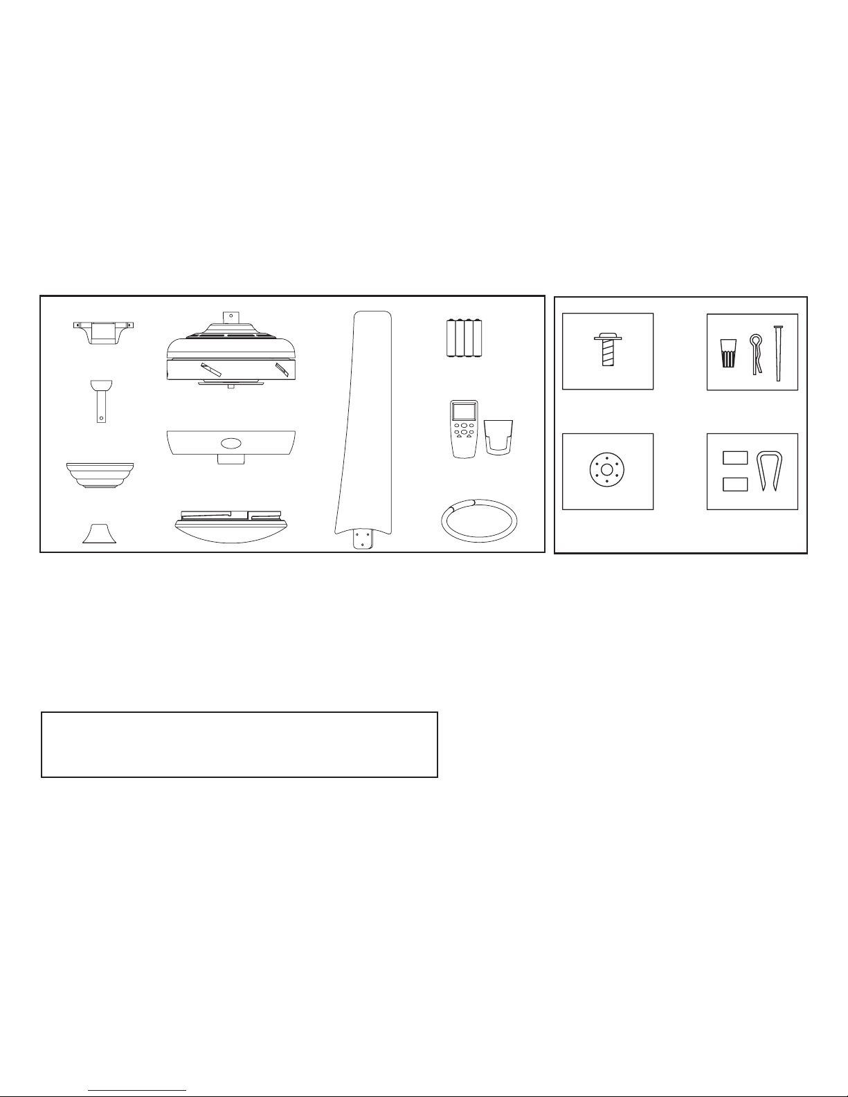
a. Blade Attachment Hardware
(16 Screws)
b. Electrical Hardware
(3 plastic wire connectors, 1 Clevis pin,
1 bolt)
c. Close-To-Ceiling Mount Hardware
(1 rubber gasket)
d. Blade Balancing Kit
7. Glass Shade
8. Blades (5)
9. Remote Batteries
10. Remote Control Hand Unit & Wall Mount
11. Circline Fluorescent Lamp
1. Slide-On Mounting Plate (inside Canopy)
2. Downrod and Ball Assembly
3. Canopy with Canopy Ring Attached
4. Decorative Motor Collar Cover
5. Fan Motor Assembly
6. Light Kit Fitter Assembly
2. Unpacking Your Fan
IMPORTANT: THIS PRODUCT AND/OR COMPONENTS ARE COVERED BY
ONE OR MORE OF THE FOLLOWING U.S. PATENTS: 5,947,436; 5,988,580;
5,971,573; 6,010,110; 6,010,306; 6,039,541; 6,046,416 AND OTHER
PATENTS PENDING.
Unpack your fan and check the contents. You should have the following items:
4.
3.
2.
1.
7.
6.
5.
8.
11.
10.
9.
c
a b
d
c
a b
d

Installing Your Fan 3.
Tools Required
Phillips screw driver, straight slot screw
driver, adjustable wrench, step ladder, and
wire cutters.
Mounting Options
If there isn’t an existing outlet box, then read
the following instructions. Disconnect the
power by removing fuses or turning off
circuit breakers.
Secure the outlet box directly to the building
structure. Use appropriate fasteners and
building materials. The outlet box and its
support must be able to fully support the
moving weight of the fan (at least 35 lbs.)
Do not use plastic outlet boxes.
Figures 1, 2, and 3 are examples of different
ways to mount the outlet box.
Note: You may need a longer downrod to
maintain proper blade clearance when installing on a steep, sloped ceiling. The maximum
angle allowable is 30˚. If the canopy touches
downrod, remove the decorative canopy
bottom cover and turn the canopy 180˚ before
attaching the canopy to the mounting plate.
To hang your fan where there is an existing
xture but no ceiling joist, you may need an
installation hanger bar as shown in Figure 4
(available at your Hampton Bay retailer).
TO REDUCE THE RISK OF FIRE, ELECTRIC
SHOCK OR PERSONAL INJURY, MOUNT
FAN ONLY TO AN OUTLET BOX MARKED
ACCEPTABLE FOR FAN SUPPORT AND
USE THE MOUNTING SCREWS PROVIDED
WITH THE OUTLET BOX. OUTLET BOXES
COMMONLY USED FOR THE SUPPORT
OF LIGHTING FIXTURES MAY NOT BE
ACCEPTABLE FOR FAN SUPPORT AND
MAY NEED TO BE REPLACED. CONSULT A
QUALIFIED ELECTRICIAN IF IN DOUBT.
Figure 1
Figure 2
Figure 4
Figure 3

2. Remove the mounting plate from the
canopy by loosening the four screws on
the top of the canopy. Remove the two
non-slotted screws and loosen the slotted
screws. This will enable you to remove the
mounting plate (Figure 6).
4.
Hanging the Fan
REMEMBER to turn off the pow-
er. Follow the steps below to hang your
fan properly.
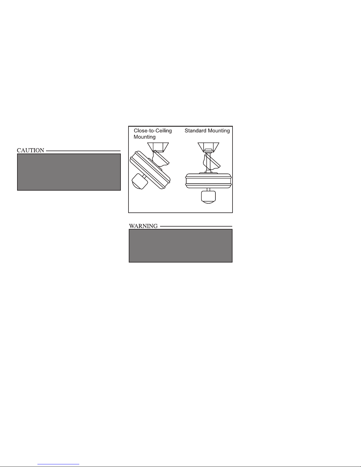
NOTE: This ceiling fan is supplied with two
types of hanging assemblies; the standard
ceiling installation using the downrod with
ball and socket mounting, and the “close-toceiling” mounting. The “close-to-ceiling”
mounting is recommended in rooms with
less than 8-foot ceilings or in areas where
additional space is desired from the oor
to the fan blades. When using standard
downrod installation, the distance from the
ceiling to the bottom of the fan blades will be
approximately 12 inches. The “close-to-ceiling”
installation reduces the distance from the
ceiling to the bottom of the fan blades to
approximately 8 inches.
Once you have decided which ceiling
installation you will use, proceed with the
following instructions. Where necessary,
each section of the instructions will note the
different procedures to follow for the two
types of installation.
Standard Ceiling Mounting
1. Remove the canopy ring from the canopy
by turning the ring to the right until it
unlocks (Figure 5).
Figure 5
Figure 6
Figure 7
3. Route the wires exiting the top of the
fan motor through the decorative motor
collar cover then the canopy ring. Make sure
the slot openings are on top. Route the wires
through the canopy and then through the
ball/downrod assembly (Figure 7).
4. Loosen, but do not remove, the set
screws on the collar on the top of the
motor housing.
5. Align the holes at the bottom of the
downrod with the holes in the collar
on top of the motor housing (Figure 7).
Carefully insert the bolt through the
holes in the collar and downrod. Be
careful not to jam the bolt against the
wiring inside the downrod. Insert the
5.
Figure 8
Figure 9
Figure 10
Figure 11
Clevis pin through the hole near the
end of the bolt until it snaps into its
locked position, as noted in the circle inset
of Figure 7.
6. Re-tighten the set screws on the collar on top
of the motor housing (Figure 8).
7. Proceed to “Installing the Fan” section.
FAILURE TO PROPERLY INSTALL CLEVIS PIN
AS NOTED IN STEP 5 COULD RESULT IN FAN
LOOSENING AND POSSIBLY FALLING.
FAILURE TO COMPLETELY TIGHTEN THE
THREE SCREWS IN STEP 7 COULD RESULT IN
FAN LOOSENING AND POSSIBLY FALLING.
WHEN USING THE STANDARD BALL/DOWNROD
MOUNTING, THE TAB IN THE RING AT THE BOTTOM OF THE MOUNTING PLATE MUST REST IN
THE GROOVE OF THE HANGER BALL. FAILURE
TO PROPERLY SEAT THE TAB IN THE GROOVE
COULD CAUSE DAMAGE TO WIRING.
Tighten Set
Screw
“Close-to-Ceiling” Mounting
1. Remove canopy ring from the canopy by
turning the ring to the right until it unlocks
(Figure 5).
2. Remove the mounting plate from the canopy
by loosening the four screws on the top of the
canopy. Remove the two non-slotted screws
and loosen the slotted screws. This will enable
you to remove the mounting plate (Figure 6).
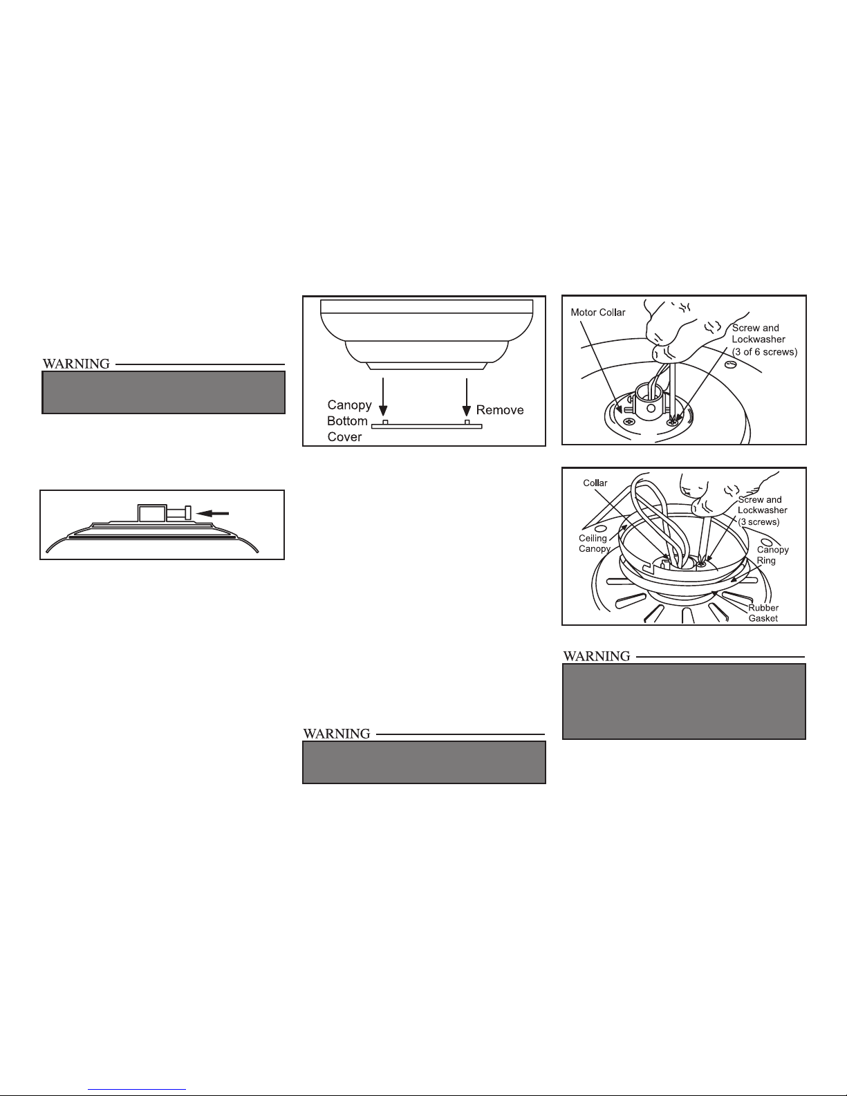
3. Remove the decorative canopy bottom cover from the canopy by depressing the three
studs (Figure 9).
4. Remove three of the six screws and lock
washers (every other one) securing the motor collar to the top of the fan motor housing
(Figure 10).
5. Place the rubber gasket over the
remaining three screws, route the wires
exiting the top of the fan motor through the
canopy ring (make sure the slot openings
are on top), then proceed to place the ceiling
canopy over the collar at the top of the motor
(Figure 11).
6. Align the mounting holes with the holes
in the motor and fasten, using the three
screws and lock-washers removed in
step 4 (Figure 11).
7. Tighten the mounting screws securely.
6.
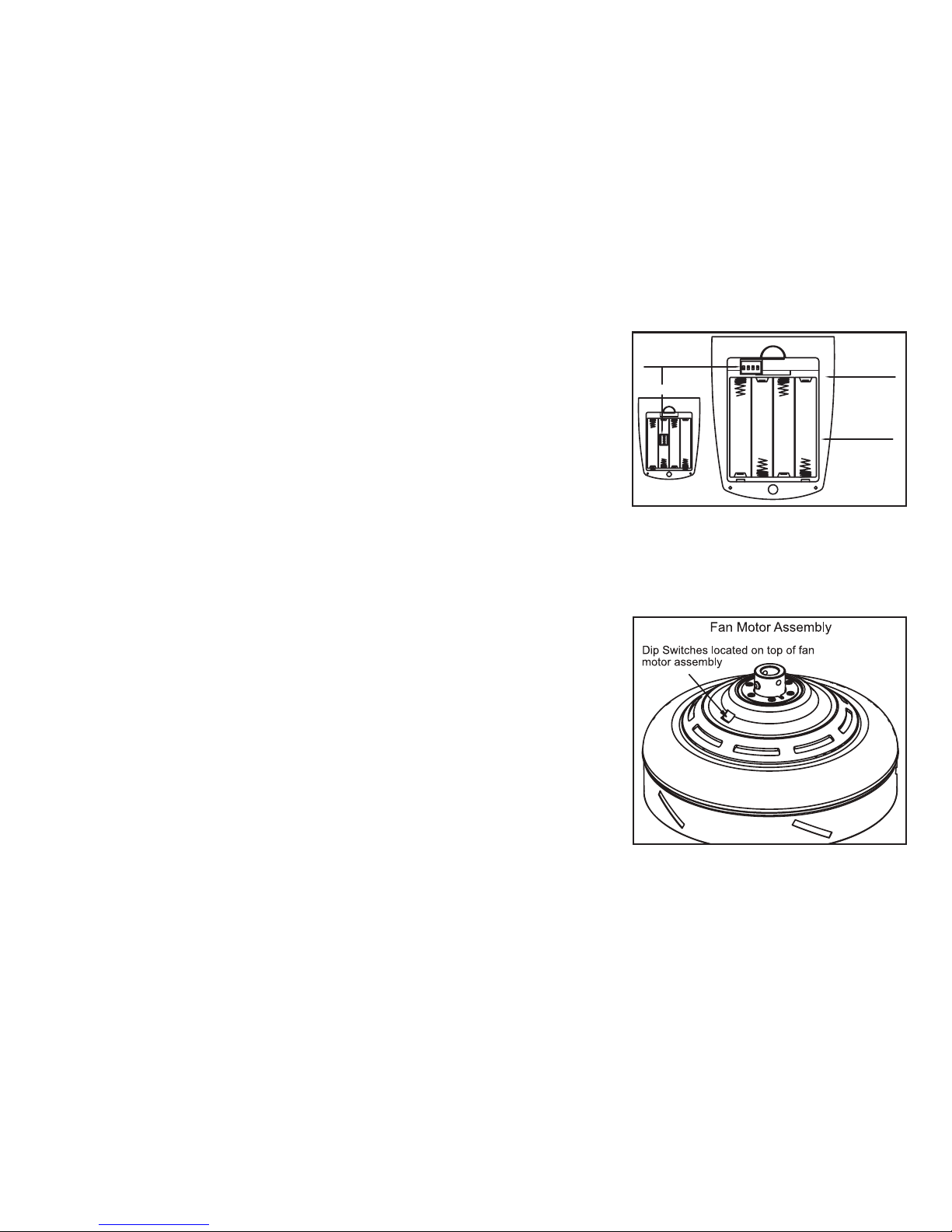
Setting the Dip Switches In
the Receiver:
In the transmitter, the dip switches are
accessible from the battery compartment
as shown in Figure A. The dip switches in
the receiver are located on top of the fan
motor assembly as shown in Figure B. The
dip switches are accessible through the top
of the motor assembly. Set the switches in
the same position as the switches in the
transmitter. After the dip switch positions
have been changed and you have assured
that they match the settings in the transmitter, turn the power on and test.
Make sure the dip switches setting in the
transmitter match the receiver.
When two or more fans are located near
each other you may want to have each set
to a different frequency so that operation
of one fan will not interfere with the other.
This can be done by changing the ON/OFF
position of any one or more of a group of 4
dip switches grouped together in the transmitter. The receiver, located on the top of
the fan motor assembly, has a similar set of
dip switches which must also be changed
to match the transmitter settings. Because
the dip switches are small, please use a ne
point instrument to adjust the settings.
2134
ON ECE
Transmitter
Battery
Compartment
Dip Switches
2134
ON ECE
Optional
Figure A
Figure B
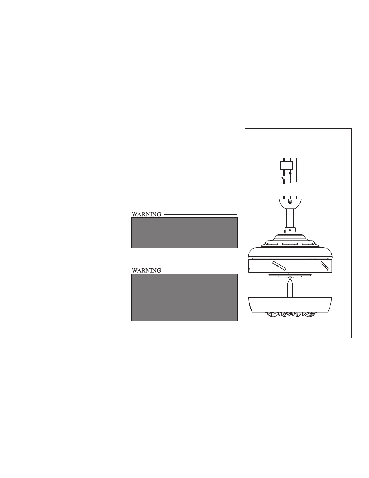
7.
Installing Fan to
the Outlet Box
1. Pass the 120-volt supply wires through the
center hole in the ceiling mounting plate as
shown in Figure 7.
2. Install the ceiling mounting plate on the
outlet box, by sliding the mounting plate
over the two screws provided with the outlet
box (Figure 7). When using close-to-ceiling
mounting, it is important that the mounting plate be level. If necessary, use leveling
washers (not included) between the mounting plate and the outlet box. Note that the
at side of the mounting plate is toward the
outlet box (Figure 7).
3. Securely tighten the two mounting screws.
4. Carefully lift the assembly up to the ceiling mounting plate. If using close-to-ceiling mounting, hang the fan on the hook
provided by utilizing one of the holes at
the outer rim of the ceiling canopy (Figure 12). If using standard mounting, seat
the hanger ball in the mounting plate
socket. Make sure the tab on the mounting plate socket is properly seated in
the groove in the hanger ball.
Figure 12
WHEN MOUNTING THE FAN ON A SLOPED
CEILING, THE STANDARD BALL/DOWNROD
MOUNTING METHOD MUST BE USED. THE
MOUNTING PLATE MUST BE MOUNTED SO
THAT THE SLOT OPENINGS ARE ON THE
LOWER SIDE BY SLIDING THE MOUNTING
PLATE FROM THE TOP DOWN.
THE HOOK AS SHOWN IN FIGURE 12 IS ONLY
TO BALANCE FAN WHILE ATTACHING WIRING.
FAILURE TO HANG AS SHOWN IN FIGURE 12
MAY RESULT IN HOOK BREAKING, CAUSING
THE FAN TO FALL. HOOK MUST PASS FROM
INSIDE TO OUTSIDE OF CANOPY.
8.
White
White
Blue
Black
Fan Motor
Housing
Light Kit Assembly
Ground
Conductor
Black
White
Green
Black
White
SUPPLY CIRCUIT
Green Ground Lead
Ground to Downrod
Diagram indicates light kit wiring
Making the Electrical
Connections
REMEMBER to disconnect the power. If
you feel you do not have enough electrical
wiring knowledge or experience, have your fan
installed by a licensed electrician.
Follow the steps below to connect the fan
to your household wiring. Use the wire
connecting nuts supplied with your fan. Secure the connectors with electrical tape.
Make sure there are no loose strands or
connections.
Step 1 Connect the fan supply (black) wire to
the black household supply wire as shown in
Figure 13.
Step 2 Connect the neutral fan (white) wire to
the white neutral household wire.
Step 3 Connect the two green fan ground wires,
located on the downrod and mounting bracket,
to the household ground wire. When using
Close-to-Ceiling mounting, there is only one
green ground wire from the ceiling mounting
bracket since the ball/downrod assembly not
used.
EACH WIRE NUT (WIRE CONNECTOR) SUPPLIED WITH THIS FAN IS DESIGNED TO ACCEPT
UP TO ONE 12 GAUGE HOUSE WIRE AND TWO
WIRES FROM THE FAN. IF YOU HAVE LARGER
THAN 12 GAUGE HOUSE WIRING OR MORE
THAN ONE HOUSE WIRE TO CONNECT TO THE
FAN WIRING, CONSULT AN ELECTRICIAN FOR
THE PROPER SIZE WIRE NUTS TO USE.
TO REDUCE RISK OF FIRE OR ELECTRIC
SHOCK, DO NOT USE A WALL MOUNTED SOLID
STATE SPEED CONTROL WITH THIS FAN. IT
WILL PERMANENTLY DAMAGE THE ELECTRONIC
CIRCUITRY.
Step 4 After connecting the wires, spread them
apart so that the green and white wires are on
one side of the outlet box and the black wire is
on the other side.
Step 5 Turn the wire connecting nuts upward
and push the wiring into the outlet box.
Figure 13
9.
Finishing the Fan
Installation
STANDARD CEILING MOUNTING
1. Align the locking slots of the ceiling canopy
with the two screws in the mounting plate.
Push up to engage the slots and turn clockwise to lock in place. Immediately tighten
the two mounting screws rmly.
2. Install the remaining two mounting
screws into the holes in the canopy and
tighten rmly.
3. Install the decorative canopy ring by
aligning the ring’s slots with the screws
in the canopy. Rotate the ring counterclockwise to lock in place.
4. You may now proceed to attaching the
fan blades.
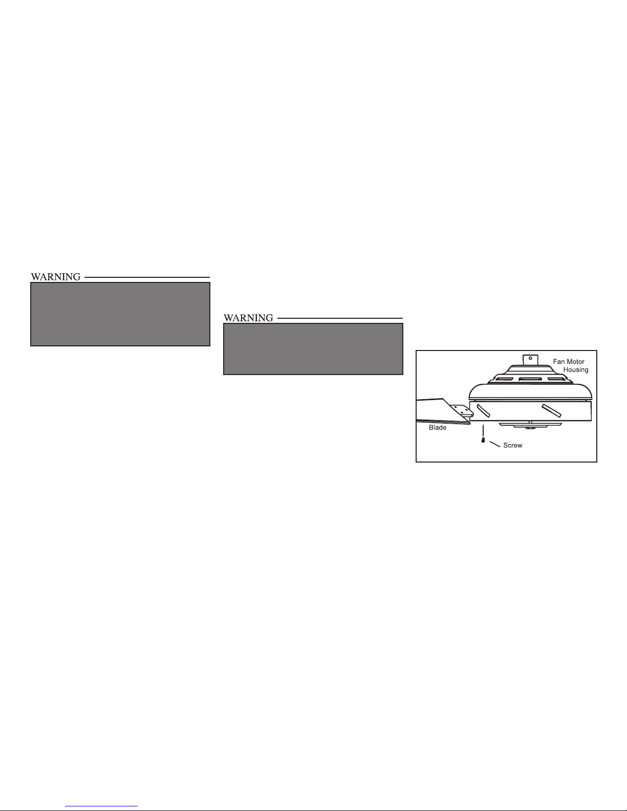
Attaching the
Fan Blades
1. Attach the blade to the fan motor housing by
inserting the blade into the slot in the side
of the fan motor housing and secure using
the screws provided as shown in Figure 14.
Start a screw into the bracket. Repeat for the
two remaining screws.
2. Tighten each screw securely.
CLOSE-TO-CEILING MOUNTING
1. Carefully unhook the fan from the mounting plate and align the locking slots of the
ceiling canopy with the two screws in the
mounting plate. Push up to engage the slots
and turn clockwise to lock in place. Immediately tighten the two mounting screws
rmly.
2. Install the remaining two mounting screws
into the holes in the canopy and tighten
rmly.
3. Install the decorative canopy ring by aligning the ring’s slots with the screws in the
canopy. Rotate the ring clockwise to lock in
place.
4. You may now proceed to attaching the fan
blades.
WHEN USING THE STANDARD BALL/DOWNROD
MOUNTING, THE TAB IN THE RING AT THE BOTTOM OF THE MOUNTING PLATE MUST REST IN
THE GROOVE OF THE HANGER BALL. FAILURE
TO PROPERLY SEAT THE TAB IN THE GROOVE
COULD CAUSE DAMAGE TO WIRING.
LOCKING SLOTS OF CEILING CANOPY ARE
PROVIDED ONLY AS AN AID TO MOUNTING. DO
NOT LEAVE FAN ASSEMBLY UNATTENDED UNTIL ALL FOUR CANOPY SCREWS ARE ENGAGED
AND FIRMLY TIGHTENED.
Figure 14
3. Repeat steps 1, 2 & 3 for the remaining
blades.
 Loading...