

HAMPTON BAY Spoleto II Spoleto II, Spoleto II 326 201 Owner's Manual

Spoleto II
52
in Ceiling Fan
Owner’s Manual
Spoleto II
Ventilador de Techo de 1,32
m
Manual del Propietario
326 201

Spoleto II by Hampton Bay
®

Date Purchased
Store Purchased
Model No.
Serial No.
Vendor No.
UPC
Thank you for purchasing our ceiling fan. This product has been
manufactured with the highest standards of safety and quality.
Table of Contents
Safety Rules . . . . . . . . . . . . . . . . . . . . 1
Unpacking Your Fan . . . . . . . . . . . . . . 2
Installing Your Fan . . . . . . . . . . . . . . . 3
Operating Your Fan . . . . . . . . . 10
Care of Your Fan . . . . . . . . . . . . . . . . 11
Troubleshooting . . . . . . . . . . . . . . . . . 11
Specifications . . . . . . . . . . . . . . . . . . 12
Warranty Information . . . . . . . . . . . . 13
326-201
219032
792145356103
52” Spoleto II
Ceiling Fan by Hampton Bay

Safety Rules - Read and Save These Instructions
1
To reduce the risk of electric shock, insure electricity has been turned off
at the circuit breaker or fuse box before beginning.
All wiring must be in accordance with the National Electrical Code
“ANSI/NFPA 70-1999” and local electrical codes. Electrical installation
should be performed by a qualified licensed electrician.
WARNING: To reduce the risk of electrical shock or fire, do not use this
fan with any solid-state fan speed control device. It will permanently
damage the electronic circuitry.
CAUTION: To reduce the risk of personal injury, use only the screws
provided with the outlet box.
The outlet box and support structure must be securely mounted and
capable of reliably supporting a minimum of 35 pounds. Use only UL
Listed outlet boxes marked “FOR FAN SUPPORT”.
The fan must be mounted with a minimum of 7 feet clearance from the
trailing edge of the blades to the floor.
Avoid placing objects in path of the blades.
To avoid personal injury or damage to the fan and other items, be
cautious when working around or cleaning the fan.
Do not use water or detergents when cleaning the fan or fan blades. A dry
dust cloth or lightly dampened cloth will be suitable for most cleaning.
After making electrical connections, spliced conductors should be turned
upward and pushed carefully up into outlet box. The wires should be
spread apart with the grounded conductor and the equipment-grounding
conductor on one side of the outlet box and ungrounded conductor on the
other side of the outlet box.
All set screws must be checked and retightened where necessary before
installation.
1.
2.
3.
4.
5.
6.
7.
8.
9.
10.
11.
WARNING
TO REDUCE THE RISK OF PERSONALL INJURY, DO NOT BEND THE
BLADE ARMS (ALSO REFERRED TO AS FLANGES), WHEN INSTALLING
THE BRACKETS, BALANCING THE BLADES OR CLEANING THE FAN. DO
NOT INSERT FOREIGN OBJECTS IN – BETWEEN ROTATING FAN
BLADES.
WARNING
TO REDUCE THE RISK OF FIRE, ELECTRIC SHOCK OR PERSONAL
INJURY, MOUNT FAN TO OUTLET BOX MARKED ACCEPTABLE FOR
FAN SUPPORT WITH THE SCREWS PROVIDED WITH THE OUTLET BOX.
2
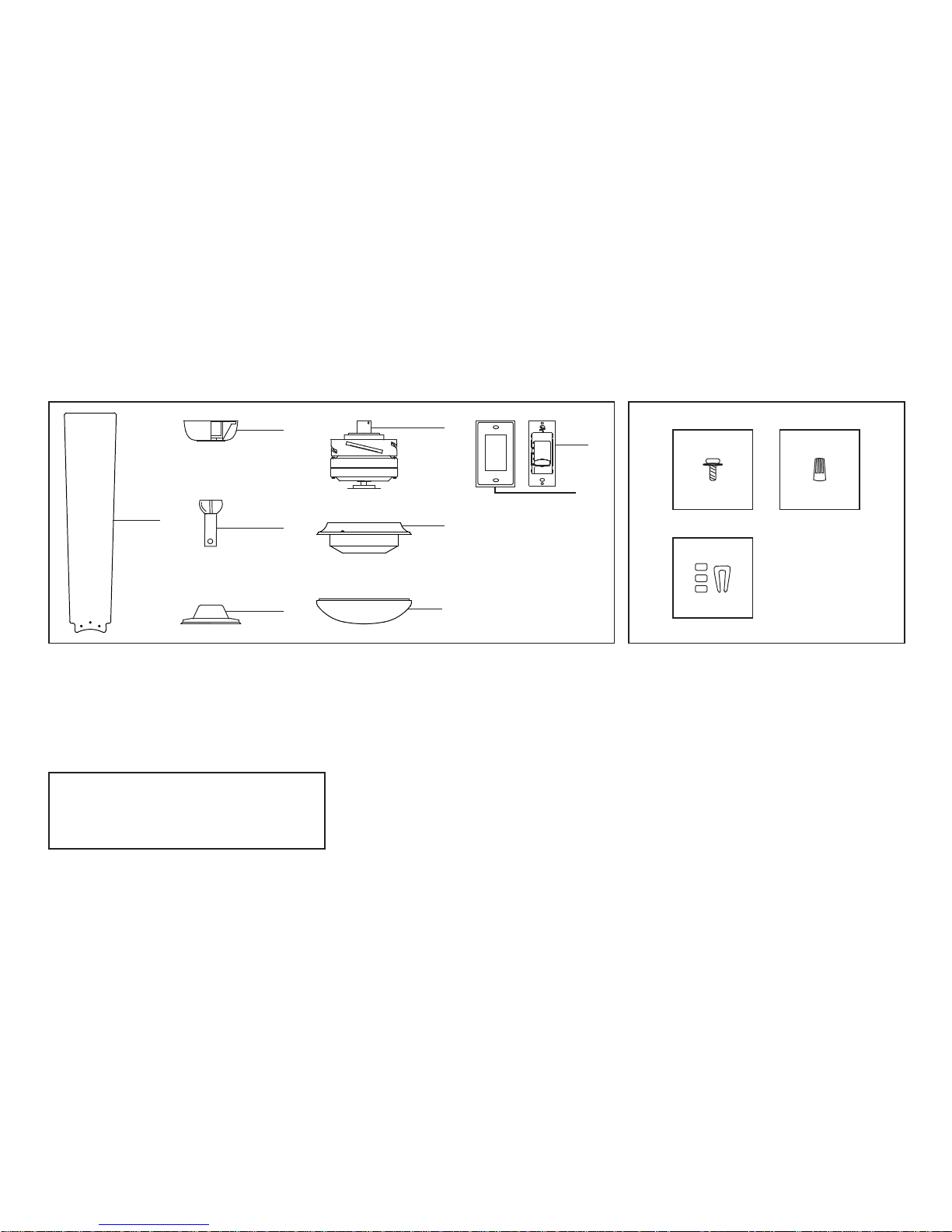
Unpacking Your Fan
Unpack your fan and check the contents. You should have the following items:
1
2
5
6
7
3
4
Set of blades (4)
Canopy assembly
Ball/downrod assembly
Coupling cover
Fan motor assembly
1.
2.
3.
4.
5.
Motor housing
Decorative cover
4-speed wall control with 2 mounting
screws and 3 wire nuts
Mounting plate with 2 mounting screws
6.
7.
8a.
8b.
WARNING
DO NOT INSTALL OR USE FAN IF ANY
PART IS DAMAGED OR MISSING.
CALL TOLL FREE 1-877-902-5588.
AB
C
A.
B.
C.
Blade Attachment Hardware
(13 Screws with Fiber Washers)
Electrical Hardware
(3 Plastic Wire Nuts)
Balancing Kit
8a
8b
 Loading...