

HAMPTON BAY H35-LP1, H35-NG1 Owners & Installation Manual
www.hampton-fi re.com
H35 Direct Vent Gas Fireplace
Owners &
Installation Manual
MODELS: H35-NG1 Natural Gas H35-LP1 Propane
WARNING:
If the information in these instructions are not followed exactly, a fi re or explosion may result causing property damage,
personal injury or loss of life.
FOR YOUR SAFETY
Do not store or use gasoline or other fl ammable vapors and
liquids in the vicinity of this or any other appliance.
Installation and service must be performed by a qualifi ed
installer, service agency or the gas supplier.
Tested by:
Installer: Please complete the details on the back cover
and leave this manual with the homeowner.
Homeowner: Please keep these instructions for future reference.
918-518a
FPI FIREPLACE PRODUCTS INTERNATIONAL LTD. 6988 Venture St., Delta, BC Canada, V4G 1H4
FOR YOUR SAFETY
What to do if you smell gas:
Do not try to light any appliance
Do not touch any electrical switch:
do not use any phone in your
building.
Immediately call your gas supplier
from a neighbour's phone. Follow
the gas supplier's instructions.
If you cannot reach your gas
supplier, call the fi re department.
01/03/08
HAMPTON
®
Direct Vent Freestanding Gas Stove
To the New Owner:
Congratulations!
You are the owner of a state-of-the-art Hampton
The H35 is a hand crafted appliance and has been designed to provide you with all the warmth and charm of a wood
fi replace at the fl ick of a switch. The model H35 has been approved by Warnock Hersey for both safety and effi ciency. As
it also bears our own mark, it promises to provide you with economy, comfort and security for many trouble free years to
follow. Please take a moment now to acquaint yourself with these instructions and the many features of your Hampton®
Stove.
®
Gas Stove by FPI FIREPLACE PRODUCTS INTERNATIONAL LTD.
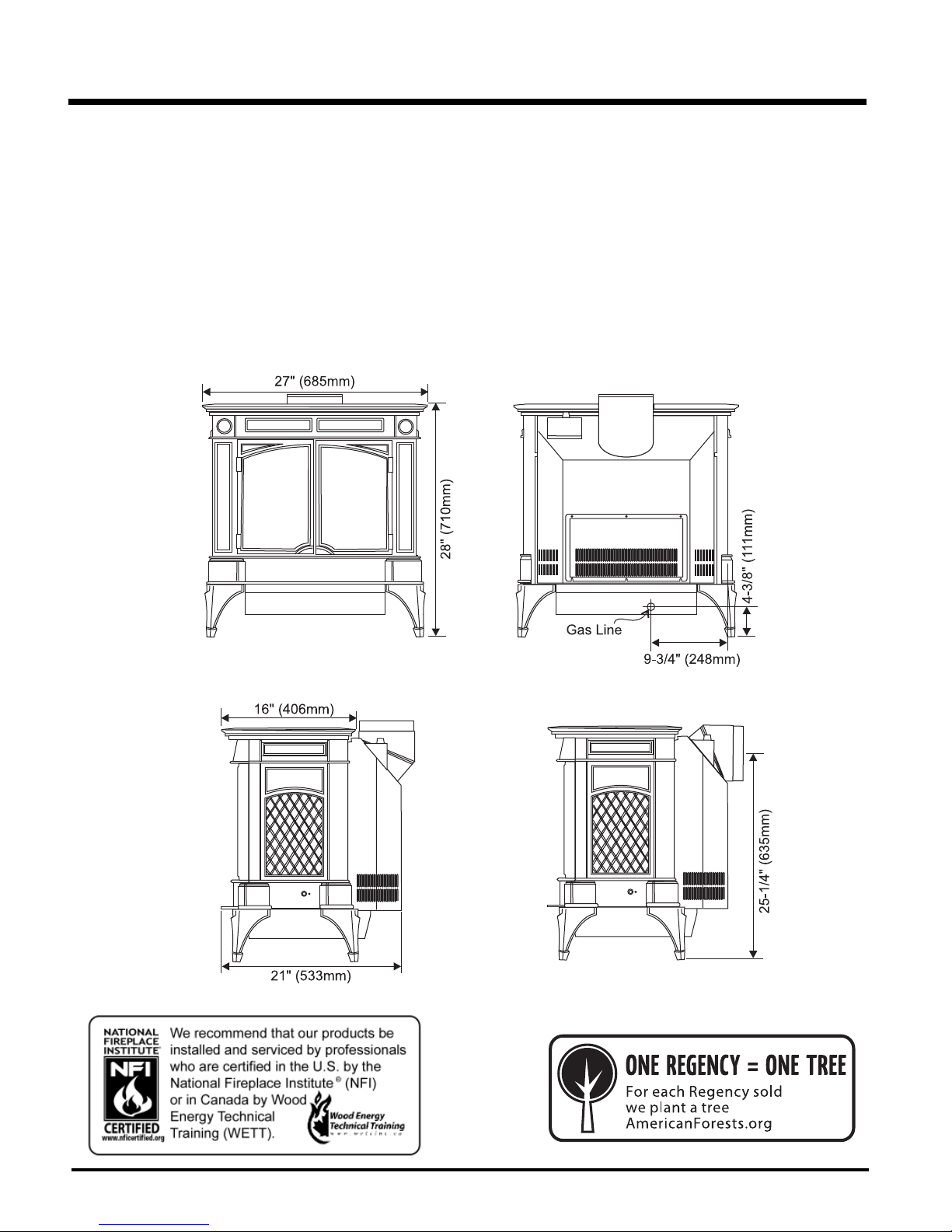
UNIT DIMENSIONS
2 Hampton® H35 Direct Vent Freestanding Gas Stove

TABLE OF CONTENTS
SAFETY LABEL
Copy of Safety Label ..................................................... 4
REQUIREMENTS
MA Code - CO Detector ................................................5
INSTALLATION
Specifi cations ................................................................6
Information for Mobile / Manufactured
Homes After First Sale .................................................. 6
General Safety Information ...........................................7
Installation Checklist ......................................................7
Clearances to Combustibles .........................................7
Locating Your Gas Stove ...............................................8
Manufactured Mobile Home Additional Requirements .. 8
Combustion and Ventilation Air ..................................... 8
Optional Fan Installation ................................................8
Venting Introduction .......................................................9
Installation Precautions .................................................9
Safety Precautions for The Installer ..............................9
Vent Restrictor Position .................................................9
Exterior Vent Terminal Locations .................................10
4” x 6-5/8” Rigid Pipe Cross Reference Chart ............. 11
Rigid Pipe Venting Systems ........................................ 13
Rotating 45o Elbow for Straight
Horizontal Terminations ...............................................14
Venting Arrangements .................................................14
Vertical Termination With Co-linear Flex System .........18
DV Stove Horizontal Vent Kit .......................................19
Dura-Vent Termination Kit ............................................21
Dura-Vent Horizontal Installations ...............................22
Dura-Vent Vertical Termination ....................................23
Converting Class-A Metal Chimney or .......................25
Masonry Chimney to Direct Vent System ....................25
Cathedral Ceilings ....................................................... 26
High Elevation .............................................................26
Gas Connection ...........................................................26
Aeration Adjustment ....................................................27
Gas Pipe Pressure Testing .......................................... 27
Conversion Kit #791-969 from NG to LP ..................... 28
Conversion Kit to Lower BTU Rating ...........................32
Optional Brick Panel ....................................................33
Log Set Installation ...................................................... 33
Double DoorInstallation ............................................... 35
Decorative Door Grill Installation .................................35
Tile Inset Installation ....................................................35
Door Hinge Removal ................................................... 36
Wiring Diagrams ..........................................................37
Wall Thermostat .........................................................38
Remote Control ..........................................................38
Final Check .................................................................39
OPERATING INSTRUCTIONS
Operating Instructions .................................................39
Lighting Procedure ......................................................39
Shutdown Procedure ................................................... 39
First Fire ......................................................................39
Copy of the Lighting Plate Instructions ....................... 40
Adjusting Flame Height ...............................................40
Automatic Convection Fan Operation .........................40
MAINTENANCE
Normal Operating Sounds of Gas Appliances .............41
Maintenance Instructions ............................................41
Fan Maintenance .........................................................42
General Vent ..............................................................42
Maintenance ................................................................42
Log Replacement ........................................................42
Glass Replacement ..................................................... 42
Removing Valve ...........................................................43
Installing Valve Assembly ............................................43
Main Assembly ............................................................44
Burner & Log Assembly ...............................................45
WARRANTY
Burner & Log Assembly ...............................................47
Hampton® H35 Direct Vent Freestanding Gas Stove
3
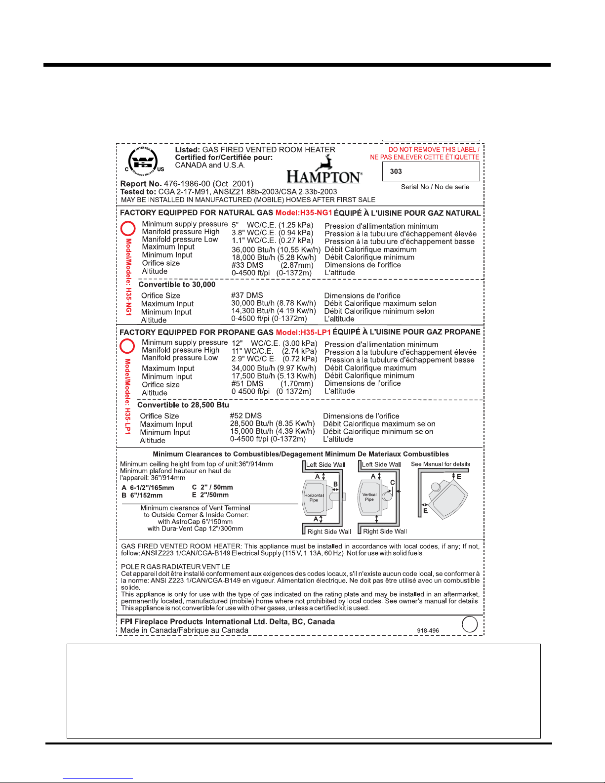
SAFETY LABEL
This is a copy of the label that accompanies
each Direct Vent Freestanding Gas Stove.
We have printed a copy of the contents here
for your review.
NOTE: Hampton® units are constantly being
improved. Check the label on the unit and if
there is a difference, the label on the unit is
the correct one.
COPY OF SAFETY LABEL
For the State of Massachusetts, installation and repair must be done by a plumber or gasfi tter licensed in the Commonwealth of
Massachusetts.
For the State of Massachusetts, fl exible connectors shall not exceed 36 inches in length.
For the State of Massachusetts, the appliances individual manual shut-off must be a t-handle type valve.
The State of Massachusetts requires the installation of a carbon monoxide alarm in accordance with NFPA 720 and a CO alarm with
battery back up in the same room where the gas appliance is installed.
4 Hampton® H35 Direct Vent Freestanding Gas Stove

REQUIREMENTS
MA Code - CO Detector
(for the State of Massachusetts only)
5.08: Modifications to NFPA-54, Chapter 10
(2) Revise 10.8.3 by adding the following additional requirements:
(a) For all side wall horizontally vented gas fueled equipment installed in every dwelling, building or structure used in whole or in part for
residential purposes, including those owned or operated by the Commonwealth and where the side wall exhaust vent termination is less than
seven (7) feet above finished grade in the area of the venting, including but not limited to decks and porches, the following requirements shall
be satisfied:
1. INSTALLATION OF CARBON MONOXIDE DETECTORS. At the time of installation of the side wall horizontal vented gas fueled
equipment, the installing plumber or gasfitter shall observe that a hard wired carbon monoxide detector with an alarm and battery back-up is
installed on the floor level where the gas equipment is to be installed. In addition, the installing plumber or gasfitter shall observe that a battery
operated or hard wired carbon monoxide detector with an alarm is installed on each additional level of the dwelling, building or structure
served by the side wall horizontal vented gas fueled equipment. It shall be the responsibility of the property owner to secure the services of
qualified licensed professionals for the installation of hard wired carbon monoxide detectors
a. In the event that the side wall horizontally vented gas fueled equipment is installed in a crawl space or an attic, the hard wired carbon
monoxide detector with alarm and battery back-up may be installed on the next adjacent floor level.
b. In the event that the requirements of this subdivision can not be met at the time of completion of installation, the owner shall have a period of
thirty (30) days to comply with the above requirements; provided, however, that during said thirty (30) day period, a battery operated carbon
monoxide detector with an alarm shall be installed.
2. APPROVED CARBON MONOXIDE DETECTORS. Each carbon monoxide detector as required in accordance with the above provisions
shall comply with NFPA 720 and be ANSI/UL 2034 listed and IAS certified.
3. SIGNAGE. A metal or plastic identification plate shall be permanently mounted to the exterior of the building at a minimum height of eight
(8) feet above grade directly in line with the exhaust vent terminal for the horizontally vented gas fueled heating appliance or equipment. The
sign shall read, in print size no less than one-half (1/2) inch in size, "GAS VENT DIRECTLY BELOW. KEEP CLEAR OF ALL
OBSTRUCTIONS".
4. INSPECTION. The state or local gas inspector of the side wall horizontally vented gas fueled equipment shall not approve the installation
unless, upon inspection, the inspector observes carbon monoxide detectors and signage installed in accordance with the provisions of 248 CMR
5.08(2)(a)1 through 4.
(b) EXEMPTIONS: The following equipment is exempt from 248 CMR 5.08(2)(a)1 through 4:
1. The equipment listed in Chapter 10 entitled "Equipment Not Required To Be Vented" in the most current edition of NFPA 54 as adopted by
the Board; and
2. Product Approved side wall horizontally vented gas fueled equipment installed in a room or structure separate from the dwelling, building or
structure used in whole or in part for residential purposes.
(c) MANUFACTURER REQUIREMENTS - GAS EQUIPMENT VENTING SYSTEM PROVIDED. When the manufacturer of Product
Approved side wall horizontally vented gas equipment provides a venting system design or venting system components with the equipment, the
instructions provided by the manufacturer for installation of the equipment and the venting system shall include:
1. Detailed instructions for the installation of the venting system design or the venting system components; and
2. A complete parts list for the venting system design or venting system.
(d) MANUFACTURER REQUIREMENTS - GAS EQUIPMENT VENTING SYSTEM NOT PROVIDED. When the manufacturer of a
Product Approved side wall horizontally vented gas fueled equipment does not provide the parts for venting the flue gases, but identifies
"special venting systems", the following requirements shall be satisfied by the manufacturer:
1. The referenced "special venting system" instructions shall be included with the appliance or equipment installation instructions; and
2. The "special venting systems" shall be Product Approved by the Board, and the instructions for that system shall include a parts list and
detailed installation instructions.
(e) A copy of all installation instructions for all Product Approved side wall horizontally vented gas fueled equipment, all venting instructions,
all parts lists for venting instructions, and/or all venting design instructions shall remain with the appliance or equipment at the completion of
the installation.
Hampton® H35 Direct Vent Freestanding Gas Stove
5
INSTALLATION
IMPORTANT MESSAGE
SAVE THESE
INSTRUCTIONS
The Direct Vent Freestanding Gas Stove must be
installed in accordance with these instructions.
Carefully read all the instructions in this manual
fi rst. Consult the building authority having
jurisdiction to determine the need for a permit
prior to starting the installation.
Note: Failure to follow the instructions
could cause a malfunction of the
heater which could result in death,
serious bodily injury, and/or property
damage. Failure to follow these
instructions may also void your fi re
insurance and/or warranty.
Note: These instructions take precedence over
Simpson Dura-Vent instructions.
SPECIFICATIONS
Fuels: H35-NG1 is approved for use with
natural gas.
H35-LP1 is approved for use
with liquefied petroleum gases
(propane).
Electrical: 120V A.C. system.
Circulation Fan: Variable speed, 125/75.
Log Sets: Ceramic fi bre, 7 per set.
Vent System: Coaxial (6-5/8" outer / 4" inner
liner) rigid fl ue and termination cap.
The effi ciency rating of the appliance is a
product thermal effi ciency rating determined
under continuous operating conditions and
was determined independent of any installed
system.
INFORMATION FOR
MOBILE /
MANUFACTURED
HOMES
AFTER FIRST SALE
This Hampton® product has been tested and
listed by ITS Testing Services as a Direct Vent
Wall Furnace to the following standards:
CGA-2.17-M91, and ANSI Z21.88b-2003/CSA
2.33b-2003.
This Direct Vent System Appliance must be
installed in accordance with the manufacturer's
installation instructions and the Manufactured
Home Construction and Safety Standard, Title
24 CFR, Part 3280, or the current Standard
of Fire Safety Criteria for Manufactured
Home Installations, Sites, and Communities
ANSI/NFPA 501A, and with CAN/CSA Z240-MH
Mobile Home Standard in Canada.
This appliance installation must comply with
the manufacturer's installation instructions and
local codes, if any. In the absence of local codes
follow the current National Fuel Gas Code, ANSI
Z223.1 and the current National Electrical Code
ANSI/NFPA 70 in the U.S.A., and the current
CAN/CGA B149 Gas Installation Code and the
current Canadian Electrical Code CSA C22.1
in Canada.
This Hampton® Mobile/Manufactured
Home Listed appliance comes factory
equipped with a means to secure the
unit.
This Hampton® Mobile/Manufactured
Home listed appliance comes equipped
with a dedicated #8 ground lug to which
an 18 gauge copper wire from the steel
chassis ground must be attached.
This appliance may only be installed in
an aftermarket permanently located,
manufactured (USA only )or mobile
home, where not prohibited by local
codes.
This appliance is only for use with
the type of gas indicated on the
rating plate. This appliance is not
convertible for use with other gases,
unless a certifi ed kit is used.
BEFORE YOU START
Safe installation and operation of this appliance
requires common sense, however, we are
required by the Canadian Safety Standards
and ANSI Standards to make you aware of
the following:
INSTALLATION AND REPAIRS SHOULD
BE DONE BY A QUALIFIED SERVICE
PERSON. THIS APPLIANCE SHOULD BE
INSTALLED, REPAIRED, INSPECTED BEFORE USE AND AT LEAST ANNUALLY BY
A QUALIFIED SERVICE PERSON. MORE
FREQUENT CLEANING MAY BE REQUIRED
DUE TO EXCESSIVE LINT FROM CARPETING, ETC. IT IS IMPERATIVE THAT THE
CONTROL COMPARTMENT, BURNERS
AND CIRCULATING AIR PASSAGEWAYS
OF THE APPLIANCE BE KEPT CLEAN.
DUE TO HIGH TEMPERATURES, THE APPLIANCE SHOULD BE LOCATED OUT OF
TRAFFIC AND AWAY FROM FURNITURE
AND DRAPERIES.
WARNING: FAILURE TO INSTALL THIS
APPLIANCE CORRECTLY WILL VOID
YOUR WARRANTY AND MAY CAUSE A
SERIOUS HOUSE FIRE.
CHILDREN AND ADULTS SHOULD BE
ALERTED TO THE HAZARDS OF HIGH
SURFACE TEMPERATURES, ESPECIALLY
THE FIREPLACE GLASS, AND SHOULD
STAY AWAY TO AVOID BURNS OR CLOTHING IGNITION.
YOUNG CHILDREN SHOULD BE CAREFULLY SUPERVISED WHEN THEY ARE IN
THE SAME ROOM AS THE APPLIANCE.
CLOTHING OR OTHER FLAMMABLE
MATERIAL SHOULD NOT BE PLACED ON
OR NEAR THE APPLIANCE.
1) Provide adequate clearances for servicing,
proper operation and around the air openings
into the combustion chamber.
2) The appliance must be installed on a fl at,
solid, continuous surface (e.g. wood, metal,
concrete). This may be the fl oor, or it can be
raised up on a platform to enhance its visual
impact. The appliance may be installed on
carpeting, tile, wood fl ooring or other combustible material, because the appliance's
base extends the full width and depth of the
appliance. The Direct Vent Freestanding
Gas Stove can be installed in a wide variety
of ways and will fi t nearly any room layout.
It may be installed in a recessed position,
framed out into the room, or across a corner.
3) The Direct Vent Freestanding Gas Stove
is approved for alcove installations, which
meet the clearances listed in the "Clearance to Combustibles" section. This unit is
approved for manufactured home installations, see the "Manufactured Mobile Home
Additional Requirements" section and the
"Venting Arrangement" section for the required vent arrangements. If installed into a
manufactured home the unit must be bolted
down to the fl oor.
4) This appliance is Listed for bedroom instal-
lations when used with a Listed Millivolt
Thermostat. Some areas may have further
requirements, check local codes before
installation.
5) This appliance is Listed for Alcove installa-
tions, maintain minimum Alcove clearances
as follows, minimum width of 40" (1016mm),
a maximum depth of 36" (914mm), and
minimum ceiling height of 64" (1626mm)
from fl oor to ceiling.
6) We recommend that you plan your instal-
lation on paper using exact measurements
for clearances and fl oor protection before
actually installing this appliance. Have a
qualifi ed building inspector review your plans
before installation.
6 Hampton® H35 Direct Vent Freestanding Gas Stove
INSTALLATION
GENERAL SAFETY
INFORMATION
1) The appliance installation must conform with
local Canadian Electrical Code.
2) The appliance when installed, must be
electrically grounded in accordance with
local codes, or in the absence of local codes
with the current National Electrical Code,
ANSI/NFPA 70 or CSA C22.1 Canadian
Electrical Code.
3) The appliance should be inspected for
shipping damage before use and serv-
iced annually by a professional service
person. More frequent cleaning may be
required due to excessive lint from carpeting, bedding material, etc. It is imperative
that control compartments, and circulating
air passageways of the appliance be kept
clean and free from excessive lint from
carpeting.
4) See general construction and assembly
instructions. The appliance and vent should
be enclosed when installed in or passing
through a living area, where children may
come in contact with it.
5) This appliance must be connected to the
specifi ed vent and termination cap to the
outside of the building envelope. Never
vent to another room or inside a building.
Make sure that the vent is fi tted as per the
instructions starting in the "Exterior Vent
Terminal Locations" section.
6) Inspect the venting system annually for
blockage and any signs of deterioration.
7) Venting terminals shall not be recessed into
a wall or siding.
8) Any safety glass removed for servicing
must be replaced prior to operating the appliance.
9) To prevent injury, do not allow anyone who
is unfamiliar with the operation to use the
fi replace.
Emissions from burning wood or gas could
contain chemicals known to the State of California to cause cancer, birth defects or other
reproductive harm.
INSTALLATION
CHECKLIST
1) Locate your appliance. Refer to the following
sections:
Introduction" to "Venting Arrangements"
sections.
2) Install Optional Fan. Refer to the "Optional
Fan Installation" section.
3) Set vent restrictors. Refer to the "Vent Re-
strictor Position" section.
4) Install venting. Refer to the following sections
where applicable:
a. Check all venting requirements.
See "Venting Introduction" to "Venting
Arrangements" sections.
b. Vertical Termination with Co-linear Flex
System
c. DV Stove Horizontal Vent Kit
d. Dura-Vent Termination Kit.
5) Make gas connections. Refer to the "Gas
Connection" section
Test the pilot. Must be as per diagram in the
"Maintenance Instruction" section.
If converting to Propane, make changes
prior see the "Conversion from Natrual Gas
to Propane" section.
6) Test Gas Pressure. Refer to the "Gas Pipe
Pressure Testing" section.
7) Install standard and optional features. Refer
to the following sections where applicable:
a. Log Set Installation
b. Double Door Installation
c. Decorative Door Grill Installation
d. Tile Inset Installation
e. Wall Thermostat
f. Remote Control
8) Final check. Refer to the "Final Check" sec-
tion.
Before leaving this unit with the customer,
the installer must ensure that the appli-
ance is fi ring correctly and operation fully
explained to customer.
This includes:
1) Clocking the appliance to ensure the correct
fi ring rate (rate noted on label) after burning
appliance for 15 minutes.
2) If required, adjusting the primary air to ensure
that the fl ame does not carbon. First allow
the unit to burn for 15-20 min. to stabilize.
CAUTION: Any alteration to the product that
causes sooting or carboning that results
in damage is not the responsibility of the
manufacturer.
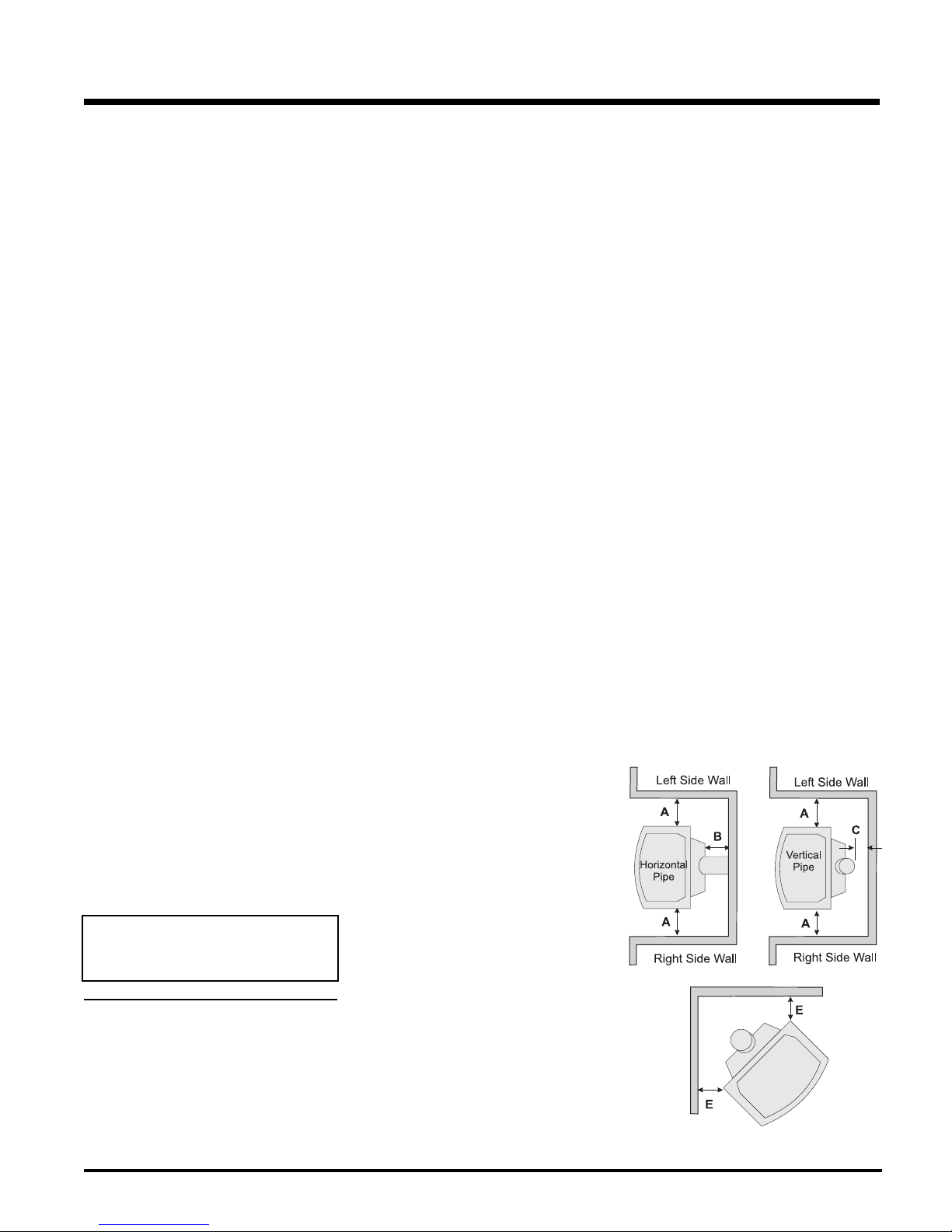
CLEARANCES TO
COMBUSTIBLES
The clearances listed are MINIMUM distances.
Measure the clearance to both the appliance
and the chimney connector. The farthest
distance is correct if the two clearances do
not coincide.
For example, if the appliance is set as indicated
in one of the fi gures but the connector is too
close, move the stove until the correct clearance
to the connector is obtained.
This appliance may be installed only with the
clearances as shown in the situations pictured.
Do not combine clearances from one type of
installation with another in order to achieve
closer clearances.
This unit can be installed on a solid combustible
surface like a wood fl oor. This unit can also be
installed directly on carpeting or vinyl.
Use the minimum clearances shown in the
diagrams below:
H35-NG1 & H35-LP1 Clearances
A Side Wall to Unit 6-1/2" / 165 mm
B Back Wall to Unit 6" / 152 mm
C Vertical Vent Pipe to Back Wall
2" / 50 mm
E Unit Corner to Wall 2" / 50 mm
Unit Top to Alcove Ceiling 36" / 914 mm
Minimum ceiling height is 36" /914 mm from
top of unit.
a. Clearances to combustibles
b. Locating Your Gas Stove
c. For venting requirements, see "Venting
Hampton® H35 Direct Vent Freestanding Gas Stove
7
INSTALLATION
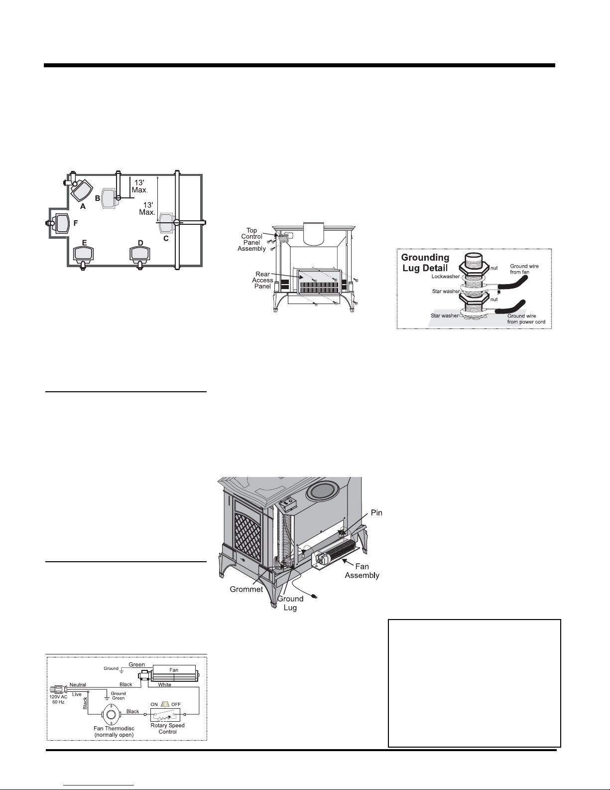
LOCATING YOUR
GAS STOVE
When selecting a location for your stove, ensure
that the clearances listed above are met as well
as ensuring that there is adequate accessibility
for servicing and proper operation.
A) Cross Corner
B) Room Divider
C) Island
D) Flat on Wall
E) Flat on Wall Corner
F) Flush with Wall/Alcove
For Vent Termination requirements, see the
"Exterior Vent Terminal Locations" section.
MANUFACTURED
MOBILE HOME
ADDITIONAL
REQUIREMENTS
1) Ensure that structural members are not cut
or weakened during installation.
2) Ensure proper grounding using the #8
ground lug provided.
OPTIONAL FAN INSTALLATION
Fan Kit Contains:
Qty. Description
1 Fan Speed Controller with nut, and
knob.
1 Fan Assembly c/w green wire
attached
1 Power cord
1 Plastic locking grommet
1) Remove the Top Control Panel Assembly
by removing the three screws. Diagram 1.
Diagram 1
2) Remove the nylon hole plug from the control
panel.
3) Install the fan speed controller onto the
control panel and secure with nut. Connect
remaining wire harness wires to speed
control. NOTE: Speed control wires must
be in the down position when control panel
is in place.
4) Push black knob onto speed control.
5) Remove the rear access panel on the back
of the stove by removing the 6 screws. Install
the fan onto pins as per Diagram 2.
7) Install locking grommet to power cord and
push through hole in the rear panel and give
a 1/4 turn to secure.
NOTE: When running wires, keep them clear
of valve assembly and tubing to avoid
tangling of wires and valve.
NOTE: Be careful not to cut wires when pass-
ing through holes in the fi rebox.
8) Run green ground wire from fan and connect
to grounding lug.
9) Connect green power cord ground wire to
grounding lug.
10) Run the neutral black wire from power cord
and connect to fan motor.
11) Run the live black wire from power cord and
connect to speed control wire.
12) Connect the white wire of the wire harness
to the fan terminal.
NOTE: Pull excess wire next to fan to
avoid excessive heat from the fi rebox.
13) Ensure all wires are pulled away from fi rebox
to avoid excessive heat and secure with
stick-on wire clip.
3) Appliance must be anchored to the fl oor
with the supplied anchoring methods.
COMBUSTION AND
VENTILATION AIR
The combustion air from this appliance is drawn
from outside the building through the outer fl ue.
Extra provision for combustion air inside the
room is not required.
8 Hampton® H35 Direct Vent Freestanding Gas Stove
Diagram 2
NOTE: Do NOT damage, cut or remove
the 3" aluminum air intake pipes.
Hint for pushing fan down onto pins - rub a
bit of dish soap on the pins so the grommets
will slide down more easily. Check to make
sure the fan is seated properly on the pins
- try to move the fan back and forth.
6) Push power cord through hole in the rear
panel 14" - 16" and tie a loose knot in the
cord on the inside to prevent the power cord
from being pulled out. Diagram 2.
14) Re-attach control panel with 3 screws, re-
versing step 1. Re-attach rear access panel
with 6 screws, reversing step 5.
NOTE: When power cord is plugged in, speed
control is in the ON position and stove is
burning, allow 10 - 15 minutes for the thermodisc (temperature switch) to activate and
turn on the Fan automatically.
WARNING:
Electrical Grounding Instructions
This appliance is equipped with
a three pronged (grounding) plug
for your protection against shock
hazard and should be plugged
directly into a properly grounded
three-prong receptacle. Do not cut
or remove the grounding prong
from this plug.
INSTALLATION
VENTING
INTRODUCTION
The Horizontal Termination Kit and the Simpson
Dura-Vent Direct Vent System Model DV-GS
venting systems, in combination with the Direct
Vent Freestanding Gas Stoves, H35-NG1, and
H35-LP1, have been tested and listed as direct
vent heater systems by Warnock Hersey.
These units use the "balanced fl ue" technology
Co-Axial system. The inner liner vents products
of combustion to the outside while the outer pipe
draws outside combustion air into the combustion chamber thereby eliminating the need to
use heated room air for combustion and losing
warm room air up the chimney.
Note: These fl ue pipes must not be
connected to any other appliance.
The gas appliance and vent system must be
vented directly to the outside of the building,
and never be attached to a chimney serving a
separate solid fuel or gas burning appliance.
Each direct vent gas appliance must use it's own
separate vent system. Common vent systems
are prohibited.
IMPORTANT
Read all instructions carefully before starting
the installation. Failure to follow these instructions may create a fi re or other safety hazard,
and will void the warranty. Be sure to check the
venting and clearance to combustible requirements. Consult your local building codes before
beginning installation.
The location of the termination cap must conform
to the requirements in the "Exterior Vent Terminal
Locations" section.
INSTALLATION
PRECAUTIONS
These venting systems are engineered products
that have been designed and tested for use
with the H35-NG1, and H35-LP1. The warranty
will be voided and serious fi re, health or other
safety hazards may result from any of the following actions:
1) Installation of any damaged Direct Vent
component
2) Unauthorized modifi cation of the Direct Vent
System
3) Installation of any component part not manu-
factured or approved by Simpson Dura-Vent
or FPI Fireplace Products International
Ltd.
4) Installation other than as instructed by Simp-
son Dura-Vent and FPI Fireplace Products
International Ltd.
Warning: Always maintain required
clearances (air spaces) to nearby
combustibles to prevent a fire
hazard. Do not fi ll air spaces with
insulation.
Be sure to check the vent termination clearance
requirements from decks, windows, soffi ts,
gas regulators, air supply inlets and public
walkways as specifi ed in the "Exterior Vent
Terminal Locations" section and in your local
building codes.
The gas appliance and vent system must be
vented directly to the outside of the building,
and never be attached to a chimney serving
a separate solid fuel or gas-burning appliance. Each direct vent gas appliance must use
it's own separate vent system. Common vent
systems are prohibited.
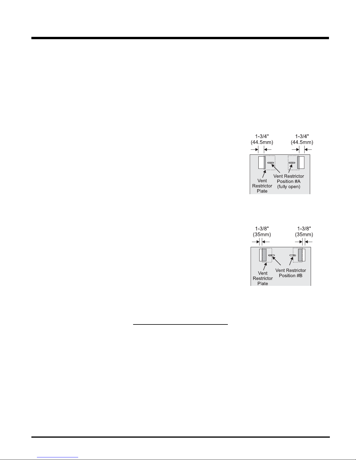
VENT RESTRICTOR
POSITION
Vent restriction is required for certain venting
installations, see the diagrams in "Venting
Arrangment" section to determine if they are
required for your installation.
To set the Vent restriction as indicated in the
diagrams in the "Venting Arrangement" section,
simply loosen the screws and push the vent
restrictor plate to the correct position. Tighten
the screws.
Horizontal Termination:
Vent Restrictor setting at 36,000 Btu/h
Vertical Termination:
Vent Restrictor setting at 36,000 Btu/h
Hampton® H35 Direct Vent Freestanding Gas Stove
SAFETY PRECAUTIONS
FOR THE INSTALLER
1) Wear gloves and safety glasses for protec-
tion.
2) Exercise extreme caution when using lad-
ders or on roof tops.
3) Be aware of electrical wiring locations in
walls and ceilings.
9
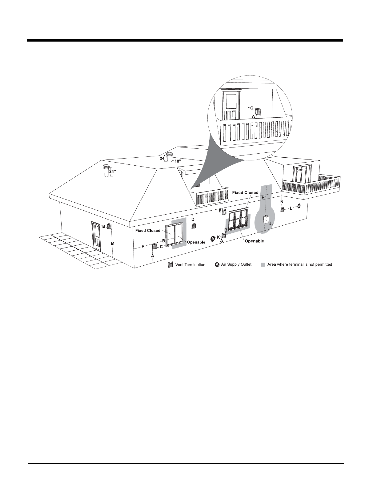
INSTALLATION
EXTERIOR VENT TERMINAL LOCATIONS
A= Clearance above grade, veranda, porch, deck, or balcony *(min. 12"/30cm)
B= Clearance to window or door that may be opened *(12"/30cm)
C= Clearance to permanently closed window *(min. 12"/30cm)
D= Vertica
E= Clearance to unventilated soffi t (min. 12"/30cm)
F= Clearance to outside corner: with AstroCap Termination Cap (min. 6"/15cm), with Dura-Vent Termination Cap (min.12"/30cm), with Riser Vent
G= Clearance to inside corner: with AstroCap Termination Cap (min. 6"/15cm), with Dura-Vent Termination C
H= Not to be installed above a meter/regulator assembly within (3'/90cm) horizontally from the centerline of the regulator.
J= Clearance to service regulator vent outlet *(min. 36"/90cm)
K= Clearance to non-mechanical air supply inlet to building or the combustion air inlet to any other appliance *(12"/30cm)
L= Clearance to a mechanical air supply inlet *(min. 72"/1.8m)
M= **Clearance above paved sidewalk or a paved driveway located on public property *(min. 84"/2.1m)
N= Clearance under veranda, porch, deck, or balcony *(min. 12"/30cm)***
Note: * As specifi ed in CGA B149 Installation Code. Note: Local codes or regulations may require different clearances.
**A vent shall not terminate directly above a sidewalk or paved drivew
dwellings.
***Only permitted if veranda, porch, deck, or balcony is fully open on a minimum of two sides beneath the fl oor.
10 Hampton® H35 Direct Vent Freestanding Gas Stove
l clearance to ventilated soffi t located above the terminal
(min. 22"/55cm) check with local code.
(min. 6"/15cm)
(min. 6"/15cm)
within a horizontal distance of (24"/60cm) from the centerline of the terminal
ap (min.12"/30cm), with Riser Vent
a
y which is located between two single family dwellings and serves both
INSTALLATION
4” X 6-5/8” RIGID PIPE CROSS REFERENCE CHART
Components from different Manufacturers may not be mixed. Not All Rigid Pipe components are available directly from FPI.
Description
6” Pipe Length, Galvanized
6” Pipe Length, Black
7” Pipe Length, Galvanized
7” Pipe Length, Black
9” Pipe Length, Galvanized
9” Pipe Length, Black
12” Pipe Length, Galvanized
12” Pipe Length, Black
18” Pipe Length, Galvanized
18” Pipe Length, Black
24” Pipe Length, Galvanized
24” Pipe Length, Black
36” Pipe Length, Galvanized
36” Pipe Length, Black
48” Pipe Length, Galvanized
48” Pipe Length, Black
60” Pipe Length, Galvanized
60” Pipe Length, Black
Adjustable Length 3”-10”, Galvanized
Adjustable Length 3”-10”, Black
Adjustable Length 11”-14”, Galvanized
Adjustable Length 11”-14”, Black
Adjustable Length 17”-24”, Galvanized
Adjustable Length 17”-24”, Black
Adjustable Length 7”, Galvanized
Adjustable Length 7”, Black
Extension Pipe 8-1/2”, Galvanized
Extension Pipe 8-1/2”, Black
Adjustable Length 12”, Galvanized
Adjustable Length 12”, Black
Extension Pipe 16”, Galvanized
Extension Pipe 16”, Black
Simpson
Direct Vent Pro
46DVA-06 908 4DT-6 N/A 4D6 SV4L6
46DVA-06B 908B 4DT-6B N/A 4D6B SV4LB6
N/A N/A N/A 4D7 N/A N/A
N/A N/A N/A 4D7B N/A N/A
46DVA-09 907 4DT-9 N/A N/A N/A
46DVA-09B 907B 4DT-9B N/A N/A N/A
46DVA-12 906 4DT-12 4D12 4D12 SV4L12
46DVA-12B 906B 4DT-12B 4D12B 4D12B SV4LB12
46DVA-18 N/A 4DT-18 N/A 4D18 SV4LA
46DVA-18B N/A 4DT-18B N/A 4D18B SV4LA
46DVA-24 904 4DT-24 4D2 4D24 SV4L24
46DVA-24B 904B 4DT-24B 4D2B 4D24B SV4LB24
46DVA-36 903 4DT-36 4D3 4D36 SV4L36
46DVA-36B 903B 4DT-36B 4D3B 4D36B SV4LB36
46DVA-48 902 4DT-48 4D4 4D48 SV4L48
46DVA-48B 902B 4DT-48B 4D4B 4D48B SV4LB48
46DVA-60 N/A N/A N/A N/A N/A
46DVA-60B N/A N/A N/A N/A N/A
N/A N/A N/A N/A 4DAL N/A
N/A N/A N/A N/A 4DALB N/A
Disc - See 46DV-08A N/A 4DT-AJ N/A N/A N/A
Disc - See 46DV-08AB 911B 4DT-AJB N/A N/A N/A
Disc - See 46DV-16A 917 - N/A from FPI N/A N/A N/A N/A
Disc - See 46DV-16AB 917B N/A N/A N/A SV4LBA24
N/A N/A N/A 4D7A N/A N/A
N/A N/A N/A 4D7AB N/A N/A
46DVA-08A N/A N/A N/A N/A N/A
46DVA-08AB N/A N/A N/A N/A N/A
N/A N/A N/A 4D12A N/A SV4LA12
N/A N/A N/A 4D12AB N/A SV4LBA12
46DVA-16A N/A N/A N/A N/A N/A
46DVA-16AB N/A N/A N/A N/A N/A
®
Simpson
Direct Vent GS
Discontinued
®
Selkirk
Direct-Temp™
American Metal
Products
Amerivent Direct
®
Metal-Fab
Sure Seal
®
Security
Secure Vent
®
45º Elbow, Galvanized
45º Elbow, Black
45º Elbow, Swivel, Galvanized
45º Elbow, Swivel, Black
90º Elbow, Galvanized
90º Elbow, Black
90º Elbow, Swivel, Galvanized
90º Elbow, Swivel, Black
90º Starter Elbow, Swivel, Galvanized*
Adaptor*
Ceiling Support
Cathedral Support Box
Wall Support/Band
Offset Support
Wall Thimble, Black
Wall Thimble Support Box/Ceiling Support
Firestop Spacer
Trim Plate, Black
Masonry Chimney Flashing
Brass Trim for Wall Thimble/Ceiling Support
Hampton® H35 Direct Vent Freestanding Gas Stove
46DVA-E45 945 4DT-EL45 4D45L N/A N/A
46DVA-E45B 945B 4DT-EL45B 4D45LB N/A N/A
Disc - See 46DVA-E45 945G N/A N/A 4D45L SV4E45
Disc - See 46DVA-
E45B
46DVA-E90 990 4DT-EL90S 4D90LS N/A N/A
46DVA-E90B 990B
Disc - See 46DVA-E90 990G N/A N/A 4D90L SV4E90-1
Disc - See 46DVA-
E90B
N/A N/A N/A N/A 4D90A N/A
N/A N/A N/A N/A 4DDA N/A
N/A 949 - N/A from FPI 4DT-CS 4DFSP 4DSP SV4SD
46DVA-CS 941 4DT-CSS 4DRSB 4DRS SV4CSB
46DVA-WS 988 4DT-WS/B 4DWS 4DWS SV4BM
46DVA-ES - N/A from FPI
46DVA-WT 942 4DT-WT 4DWT 4DWT SV4RSM
46DVA-DC N/A N/A N/A N/A SV4PF
46DVA-FS 963 4DT-FS 4DFSP 4DFS SV4BF
N/A N/A 4DT-TP 4DFPB 4DCP SV4LA
N/A N/A N/A N/A N/A N/A
DISC. 3951 N/A N/A N/A N/A
945BG N/A N/A 4D45LB SV4EB45
4DT-EL90SB
990BG N/A N/A 4D90LB SV4EB90-1
989 - N/A from FPI 4DT-OS N/A N/A SV4SU
4D90LBS N/A SV4EBR90-1
11
INSTALLATION
4” x 6-5/8” Rigid Pipe Cross Reference Chart (Cont.)
Components from different Manufacturers may not be mixed. Not All Rigid Pipe components are available directly from FPI.
Description
Attic Insulation Shield 12”
Attic Insulation Shield - Cold Climates 36”
Simpson
Direct Vent Pro
46DVA-IS - N/A from FPI
N/A N/A N/A 4DAIS36 N/A N/A
®
Simpson
Direct Vent GS
Discontinued
N/A N/A 4DAIS12 N/A SV4RSA
®
Selkirk
Direct-Temp™
American Metal
Products
Amerivent Direct
®
Metal-Fab
Sure Seal
®
Security
Secure Vent
®
Basic Horizontal Termination Kit (A)
Horizontal Termination Kit (B)
Vertical Termination Kit
High Wind Vertical Cap
High Wind Horizontal Cap
Horizontal Square Termination Cap
Vertical Termination Cap
Storm Collar
Adjustable Flashing, 0/12-6/12
Adjustable Flashing, 6/12-12/12
Vinyl Siding Standoff
Vinyl Siding Shield Plate
Snorkel Termination 14”
Snorkel Termination 36”
Restrictor Disk
Extended Vertical Termination Cap
Chimney Conversion Kit A
Chimney Conversion Kit B
Chimney Conversion Kit C
Chimney Conversion Kit Masonry
Mansonry Chimney Conversion Kit
(includes: Cap Adapter 18”x18” Flashing)
Wall Firestop
Colinear Flex Connectors
FPI
946-506/P Vent Guard (Optional) for AstropCap 946-205 Vinyl Siding Shield for Riser Vent Terminal
510-994 Rigid Pipe Adapter (Must use with all Rigid Piping) 946-208/P Vent Guard (Optional) for Riser Vent Terminal
640-530/P Riser Vent Terminal 946-523/P AstroCap Horizontal Cap
DISC. 970 4DT-HKA 4DHTK2 4DHTKA SV - SHK
46DVA-KHA
(Changed Components)
DISC. 978 4DT-VKC 4DVTK 4DVTK SV - FK
46DVA-VCH 991 N/A N/A N/A N/A
46DVA-HC 985 N/A N/A N/A N/A
Disc - See 46DVA-HC 984 4DT-HHC 4DHC 4DHT SV4CHC-1
46DVA-VC 980 4DT-HVC 4DVC 4DVT SV4CGV-1
46DVA-SC 953 4DT-SC 4DSC 4DSC SV4FC
46DVA-F6 943 4DT-AF6 4DF 4DF SV4FA
46DVA-F12 943S 4DT-AF12 4DF12 4DF-12 SV4FB
46DVA-VSS 950 4DT-VS N/A 4DVS SV4VS
N/A N/A 4DT-VSP N/A N/A SV4VS
46DVA-SNK14 982 4DT-ST14 4D12S 4DST14 SV4STC14
N/A 981 4DT-ST36 4D36S 4DST36 SV4STC36
46DVA-RD 929 N/A N/A N/A N/A
46DVA-VCE 930 N/A N/A N/A N/A
46DVA-KCA 931 N/A N/A N/A N/A
46DVA-KCB 932 N/A N/A N/A N/A
46DVA-KCC 933 N/A N/A N/A N/A
46DVA-KMC 934 N/A N/A N/A N/A
46DVA-KCT 935 N/A N/A N/A N/A
46DVA-WFS 947 N/A N/A N/A N/A
46DVA-ADF 923F N/A N/A N/A N/A
971 4DT-HKB 4DHTK1 4DHTKB SV - HK
946-206 Vinyl Siding Standoff for AstroCap
*NOTE: When using Metal-Fab Sure Seal Rigid Piping please note that either the Adaptor (4DDA) or 90º Starter Elbow (4D90A)
must be used in conjunction with FPI Rigid Pipe Adaptor (510-994).
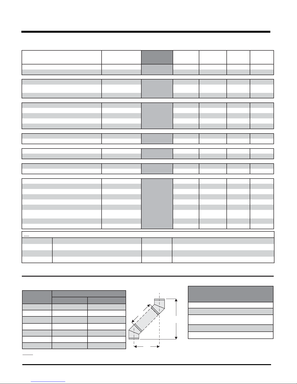
Offset Pipe Selection:
Use this table to determine offset pipe lengths.
Pipe Length
0”(0mm) 4-7/8”(124mm) 13-3/8”(340mm)
6”(152mm) 8”(203mm) 16-1/2”(419mm)
9”(229mm) 10-1/8”(257mm) 18-5/8”(473mm)
12”(305mm) 12-1/4”(311mm) 20-3/4”(527mm)
24”(610mm) 20-5/8”(524mm) 29-1/8”(740mm)
36”(914mm) 29”(737mm) 37-1/2”(953mm)
48”(1219mm) 37-7/16”(951mm) 45-15/16”(1167mm)
NOTE: Horizontal runs of vent must be level, or have a 1/4 inch rise for every 1 foot of run towards
the termination. Never allow the vent to run downward. This could cause high temperatures and
may present a possible fi re hazard.
12 Hampton® H35 Direct Vent Freestanding Gas Stove
4” x 6-5/8” Venting
Run (X) Rise (Y)
For specifi c instructions or details on particular
venting components please visit the following
websites:
Simpson Direct Vent Pro: www.duravent.com
L
Y
Selkirk Direct-Temp: www.selkirkcorp.com
American Metal Products Amerivent Direct:
www.americanmetalproducts.com
Metal-Fab Sure Seal: www.mtlfab.com
Security Secure Vent: www.securitychimneys.com
X
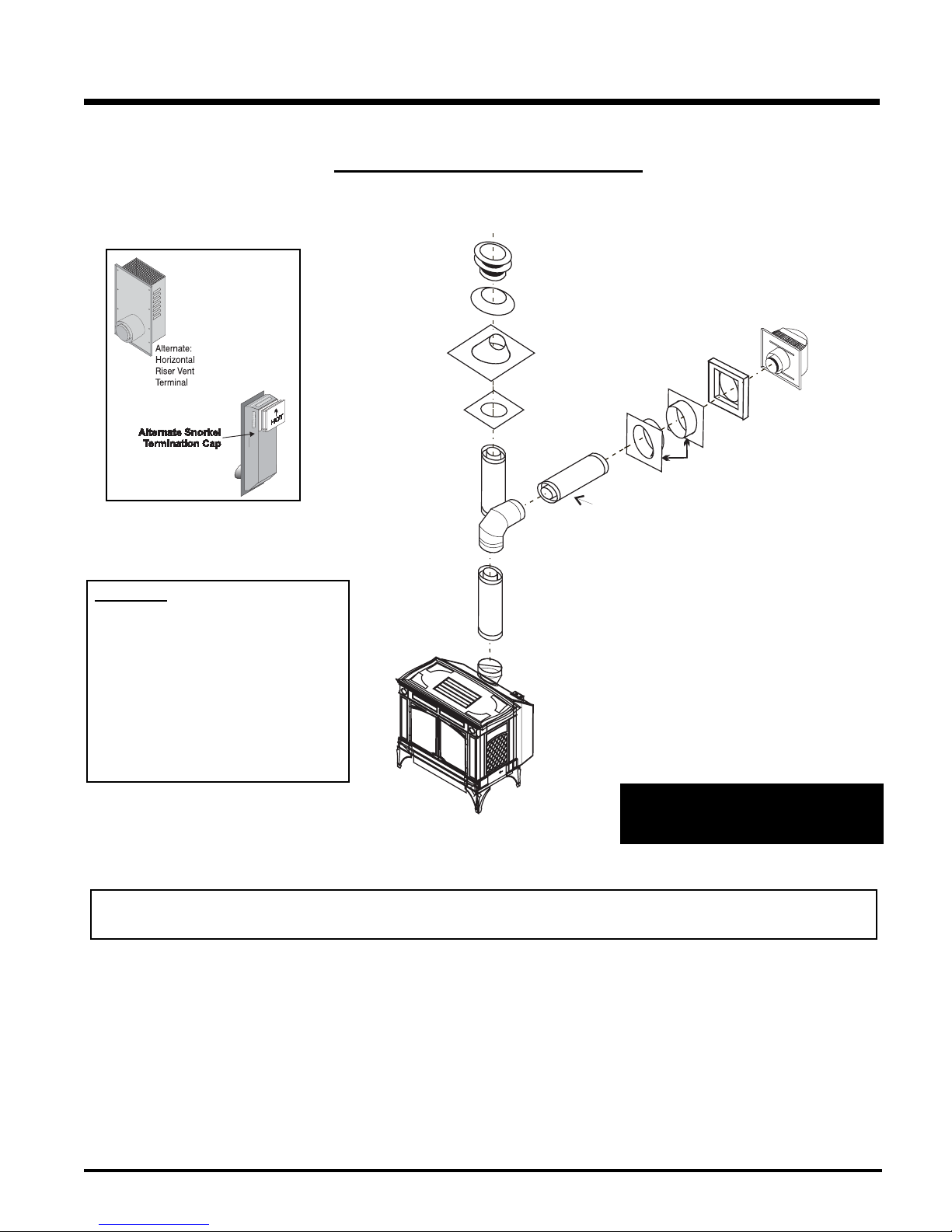
Alternate
Horizontal
Termination
Caps
RIGID PIPE VENTING SYSTEMS
Horizontal or Vertical Terminations
Vertical
Termination
Cap
Storm Collar
Vinyl Siding
Flashing
Ceiling Firestop
Standoff (Optional)
INSTALLATION
Horizontal
Termination
Cap
Wall Thimble
Pipe Length
Adj.Pipe Length
11" - 14-5/8"
o
90 Elbow
WARNING:
Do not combine venting components from
different venting systems.
However use of the the AstroCapTM and FPI
Riser is acceptable with all systems.
This product has been evaluated by Intertek
for use with Duravent Direct-Vent GS, Selkirk
Direct-Temp, Ameri Vent Direct venting and
Security Secure Vent systems.
The FPI AstroCap
American Metal Products Ameri Vent Direct Vent, Security Secure Vent®, Selkirk Direct-Temp. AstroCapTM is a proprietary trademark of FPI Fireplace
Products International Ltd. Dura-Vent® and Direct Vent GS are registered and/or proprietary trademarks of Simpson Dura-Vent Co. Inc.
TM
and FPI Riser Vent terminal are certifi ed for installations using FPI venting systems as well as Simpson Dura-Vent® Direct Vent GS,
24" Pipe
Length
When using Rigid Vent other than
Simpson Dura-Vent, 3 screws must be
used to secure rigid pipe to adaptor.
Hampton® H35 Direct Vent Freestanding Gas Stove
13
INSTALLATION
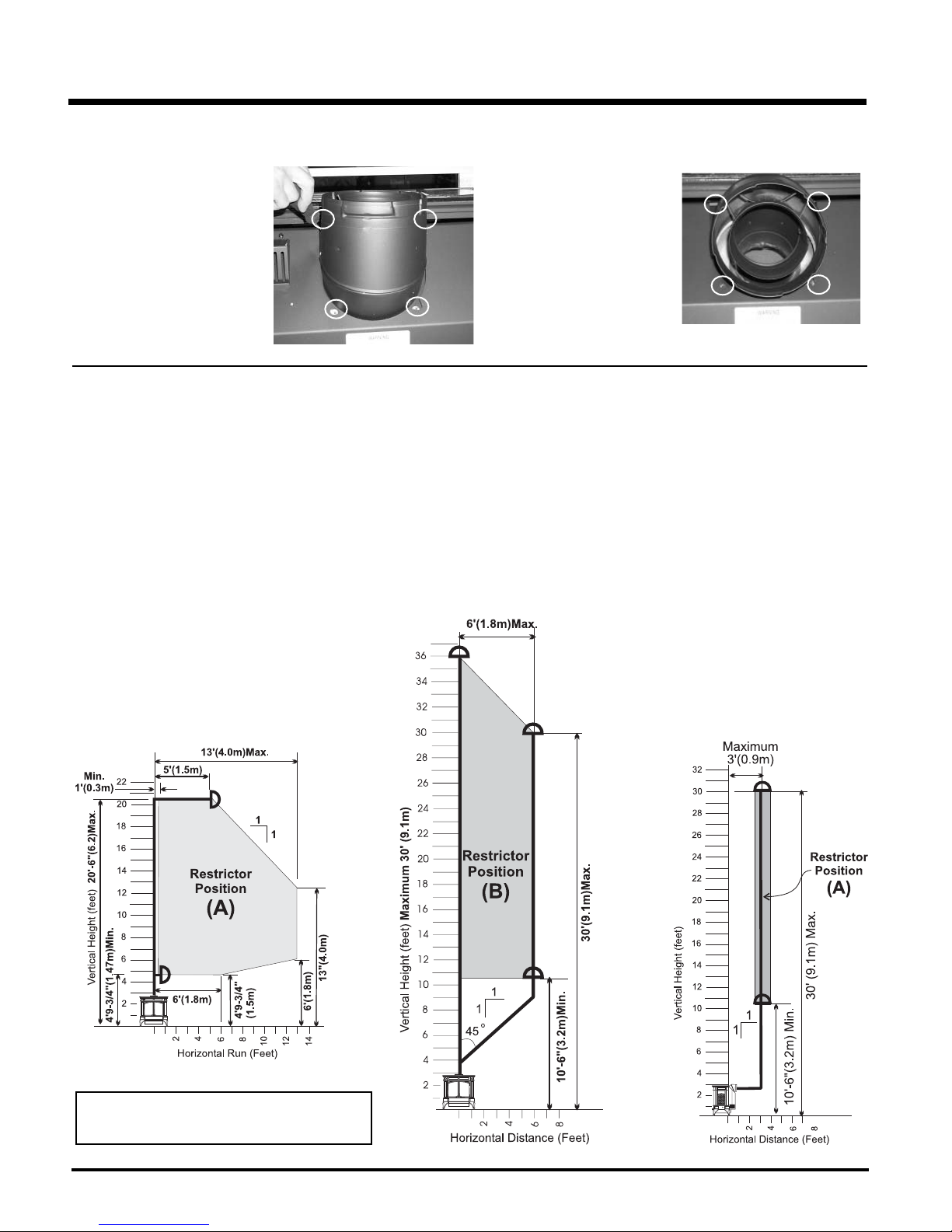
ROTATING 45O ELBOW FOR STRAIGHT HORIZONTAL TERMINATIONS
1) Remove all 4 screws that secure
the elbow to the unit using a 1/4"
magnetic nut driver.
Remove all 4 screws
and washers
Horizontal Terminations for All
Venting Systems
The shaded areas in the diagram below show
all allowable combinations of vertical runs
with horizontal terminations. Maximum one
90O elbow (two 45o elbows equal one 90o
elbow).
Propane and Natural Gas:
Residential, Manufactured and
Mobile Homes Installations
2) Rotate the elbow 180
3) Secure the elbow by securing
it with the 4 screws.
o
VENTING ARRANGEMENTS
Vertical Terminations Systems for
Residential Manufactured and Mobile Homes
The shaded area in the diagram below shows all allowable combinations of straight vertical
and offset to vertical runs with vertical terminations. Maximum two 45o elbows.
If the vent is ENCLOSED in a chase (min. size 9" x 9") maintain a 1-1/4" clearance to combustibles.
May be installed in Manufactured (Mobile) Homes after fi rst sale.
Offset to Vertical Terminations
The venting arrangements diagrammed below,
have a min. of 75% (fl ue loss) effi ciency with Fan
Off, as required for manufactured homes. (Actual
effi ciency may be as high as 85%)
May be installed in Manufactured (Mobile)
Homes after fi rst sale.
NOTE: See "Vent Restrictor Position" section for
installation instructions for the Vent Restrictor
Position.
14 Hampton® H35 Direct Vent Freestanding Gas Stove
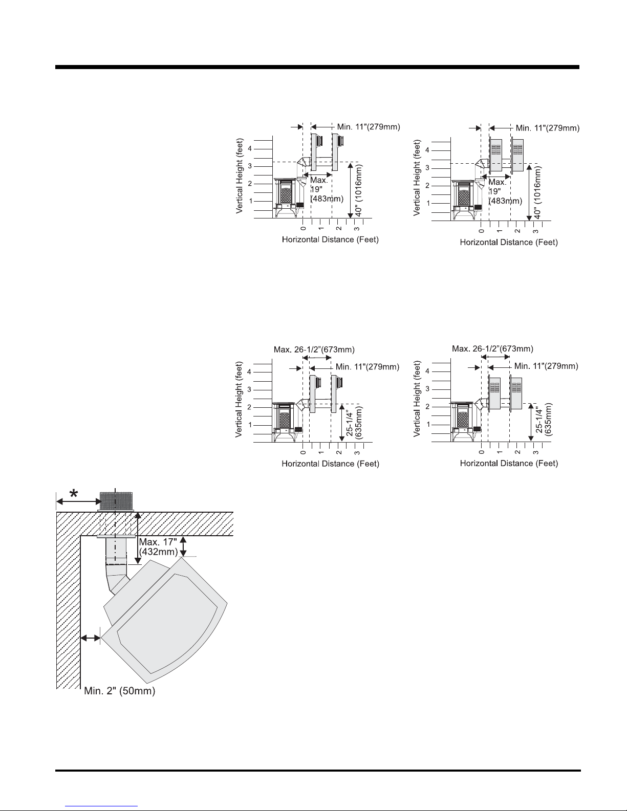
HORIZONTAL TERMINATIONS USING RIGID PIPE
The two diagrams show all allowable combinations of straight horizontal termination
using Rigid Pipe. Restrictor position "A".
INSTALLATION
VENTING ARRANGEMENTS
Venting Arrangements -Straight Horizontal Termination at a De-Rated BTU
The diagrams show all allowable combinations of straight horizontal termination using
Rigid Pipe. Restrictor position "A". Refer to
the "Conversion Kit to Lower BTU Rating"
section for de-rating instructions.
Dura-Vent Snorkel Termination
Dura-Vent Snorkel Termination
Riser Vent Termination
Riser Vent Termination
*If this is an outside corner, the minimum distance between the vent and the outside corner
is 6” (15cm). See “F” on the diagram in the
"Exterior Vent Terminal Locations" section.
Hampton® H35 Direct Vent Freestanding Gas Stove
15
 Loading...