

HAMPTON BAY H300 Owners & Installation Manual
Freestanding Woodstove
Owners &
Installation Manual
Tested by:
Homeowner: Please keep these instructions for future reference.
FPI FIREPLACE PRODUCTS INTERNATIONAL LTD. 6988 Venture St., Delta, BC Canada, V4G 1H4918-214e
www.hampton-re.com
French Manual: http://bit.ly/1jJpAoo
MODEL: H300
Installer: Please complete the details on the back cover
and leave this manual with the homeowner.
01/06/15
Thank-you for purchasing a
HAMPTON FIREPLACE PRODUCT.
The pride of workmanship that goes into each of our products will give you years of trouble-free enjoyment. Should you
have any questions about your product that are not covered in this manual, please contact the HAMPTON DEALER
in your area.
Keep those HAMPTON FIRES burning.
SAFETY NOTE: If this woodstove is not properly installed, a house re may result. For your safety, follow the installation instructions, contact local building, re ofcials, or authority having jurisdiction about restrictions and installation
inspection requirements in your area.
The authority having jurisdiction should be consulted before installation to determine the need to obtain a permit.
2
Hampton H300 Cast Freestanding Woodstove

TABLE OF CONTENTS
SAFETY LABEL
Copy of Safety Label for H300 ......................................4
INSTALLATION
Unit Dimensions with Standard Legs.............................5
Unit Dimensions with Optional Short Legs ....................6
Pre-installation Assembly ..............................................7
Residential Installation...................................................8
Modular Installation Options .......................................... 8
Minimum Clearance To Combustible Materials .............9
Minimum Alcove Clearance To
Combustible Materials .................................................10
Additional Clearances For Backwall Exit ..................... 10
Floor Protection ........................................................... 11
How To Determine If Alternate
Floor Protection Materials Are Acceptable...................12
Step-by-Step Chimney and Connector Installation......12
Factory Built Chimney .................................................12
Masonry Chimney........................................................13
Masonry Fireplace .......................................................13
Combustible Wall Chimney Connector
Pass-throughs .............................................................14
Recommended Heights For Woodstove Flue ..............15
Mobile Home Installation .............................................16
Listed Components For Mobile Home Installation ....... 17
Brick Installation ..........................................................18
Door Removal..............................................................18
Glass Installation .........................................................18
Optional Short Leg Installation ....................................19
Optional Blower / Fan Installation ................................ 21
Side Shelf Installation ..................................................22
OPERATING INSTRUCTIONS
Operating Instructions .................................................23
Fan Operation..............................................................23
First Fire ......................................................................23
Safety Guidelines and Warnings .................................24
Draft Control ................................................................24
Ash Disposal................................................................25
Creosote ......................................................................26
Glass Maintenance ......................................................26
MAINTENANCE
Maintenance ................................................................26
Wood Storage ..............................................................26
Front Door Gasket .......................................................27
Side Door Gasket ........................................................27
Handle Replacement ...................................................27
Latch Adjustment Method ............................................ 27
Side Door Adjustment .................................................. 27
Top Bafe Replacement ..............................................28
Annual Maintenance ....................................................29
PARTS LIST
H300 Main Assembly ................................................... 30
H300 Door Assembly ................................................... 32
H300 Firebrick .............................................................33
WARRANTY
Warranty ......................................................................35
http://oee.nrcan.gc.ca/residential/personal/retrot-homes/retrot-qualify-grant.cfm
Hampton H300 Cast Freestanding Woodstove
33
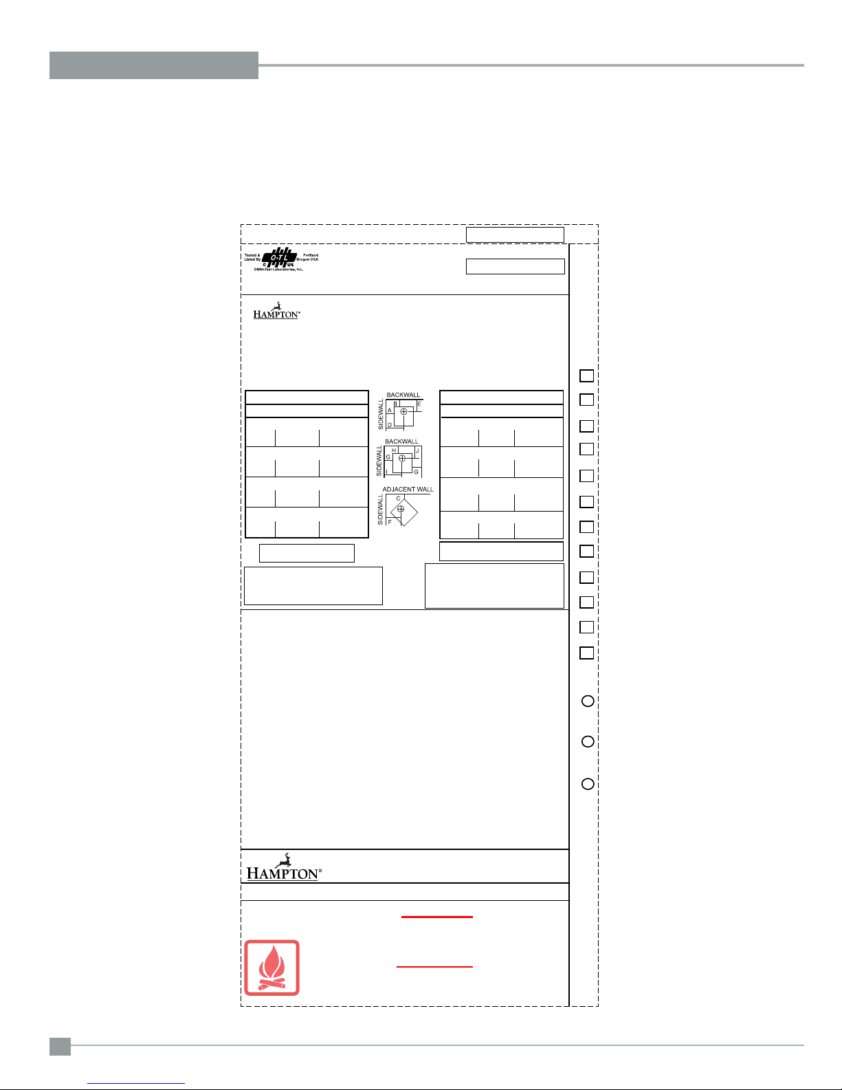
SAFETY LABEL
This is a copy of the label that accompanies
each Hampton H300 Freestanding Woodstove.
We have printed a copy of the contents here
for your review.
COPY OF SAFETY LABEL FOR H300
MINIMUM CLEARANCES TO
COMBUSTIBLE MATERIALS
MEASURE FLUE
FROM HEATER CENTER-LINE
RESIDENTIAL INSTALLATION USING
SIDEWALL A 431 mm / 17 in D 762 mm / 30 in
BACKWALL B 381 mm / 15 in E 381 mm / 15 in
CORNER C 330 mm / 13 in F 483 mm / 19 in
INSTALLATION USING LISTED DOUBLE WALL
CONNECTOR - MOBILE HOME
SIDEWALL A 381 mm / 15 in D 711 mm / 28 in
BACKWALL B 254 mm / 10 in E 254 mm / 10 in
CORNER C 228 mm / 9 in F 381 mm / 15 in
INSTALLATION USING LISTED DOUBLE WALL
CONNECTOR - RESIDENTIAL CLOSE CLEARANCE
SIDEWALL A 381 mm / 15 in D 711 mm / 28 in
BACKWALL B 254 mm / 10 in E 254 mm / 10 in
CORNER C 228 mm / 9 in F 381 mm / 15 in
INSTALLATION USING LISTED DOUBLE WALL
SIDEWALL G 381 mm / 15 in I 711 mm / 28 in
BACKWALL H 330 mm / 13 in J 330 mm / 13 in
* In Canada, fl oor protection must extend 18"
(457mm) to the front and 8" (200mm) to each
side and back of the stove.
Floor protection must extend 18" (457mm) from the side of the
unit to the wall.
Floor protection must be a minimum of 3/8" thick with a minimum k factor of 0.84.
Minimum clearance with side load door in use is 18" (457mm) to
side wall or refer to dimension (A) if side load door is not used.
MINIMUM ALCOVE CEILING HEIGHT: 1.5 M / 5 FT MAXIMUM ALCOVE DEPTH 1220 MM / 48 IN.
MINIMUM CLEARANCES FOR HORIZONTAL CONNECTOR TO CEILING: 457 MM / 18"
THE SPACE BENEATH THE HEATER MUST NOT BE OBSTRUCTED. OPERATE ONLY WITH FIREBRICKS IN PLACE.
FOR USE WITH SOLID WOOD FUEL ONLY. USE OF OTHER FUELS MAY DAMAGE HEATER AND CREATE A HAZARDOUS CONDITION. DO NOT OBSTRUCT
COMBUSTION AIR OPENINGS. OPERATE ONLY WITH FIREBRICKS IN PLACE. OPERATE ONLY WITH DOOR CLOSED - OPEN FEED DOOR TO FEED FIRE
ONLY. DO NOT USE GRATE OR ELEVATE FIRE. BUILD WOOD FIRE DIRECTLY ON HEARTH. DO NOT OVERFIRE - IF HEATER OR CHIMNEY CONNECTOR
GLOWS YOU ARE OVERFIRING. INSPECT AND CLEAN CHIMNEY AND CONNECTOR FREQUENTLY. UNDER CERTAIN CONDITIONS OF USE CREOSOTE
BUILDUP MAY OCCUR RAPIDLY. KEEP FURNISHINGS AND OTHER COMBUSTIBLE MATERIAL AWAY FROM HEATER. REPLACE GLASS ONLY WITH
NEOCERAM GLASS. COMBUSTIBLE FLOOR MUST BE PROTECTED BY NON-COMBUSTIBLE MATERIAL EXTENDING BENEATH THE HEATER AND TO
THE FRONT AND SIDES AS INDICATED OR TO THE NEAREST PERMITTED COMBUSTIBLE MATERIAL.
OPTIONAL COMPONENT: FAN (846-515), ELECTRICAL RATING: VOLTS 115, 60 HZ, 2 AMPS, SHORT LEGS (200-931, 200-935)
DANGER: RISK OF ELECTRIC SHOCK. DISCONNECT POWER BEFORE SERVICING UNIT. DO NOT ROUTE POWER CORD UNDER OR IN FRONT OF
APPLIANCE.
COMPONENTS REQUIRED FOR MOBILE HOME INSTALLATION: OUTSIDE AIR KIT AND ONE OF THE FOLLOWING DOUBLE WALL CONNECTOR
IN CANADA: LISTED SECURITY MODEL DP, OR OLIVER MACLEOD PRO-VENT PV DOUBLE WALLED CONNECTOR WITH LISTED CHIMNEY SYSTEM:
SECURITY MODEL S2100, ICC EXCEL 2100.
IN USA: LISTED DOUBLE WALL CONNECTORS SECURITY MODEL DP, SELKIRK MODEL DS, OLIVER MACLEOD PRO VENT PV, SIMPSON DURA VENT
MODEL DVL, GSW SUPER PIPE 6, METAL-FAB DOUBLE WALL. CONNECTED TO ONE OF THE FOLLOWING COMPATIBLE CHIMNEY SYSTEMS SECURITY
MODEL S2100 OR MODEL ASHT, SELKIRK MODEL SSII, OLIVER MACLEOD PRO JET 3103, SIMPSON DURA PLUS, GSW MODEL SC OR METAL-FAB
TEMP/GUARD, AMERI-TECHS, ICC EXCEL 2100 . USE CHIMNEY COMPONENTS AS SPECIFIED IN INSTALLATION INSTRUCTIONS.
HAUTEUR MINIMALE DU PLAFOND DE L’ALCÔVE : 1,5 M / 5 PI. PROFONDEUR MAXIMALE DE L’ALCÔVE : 1220 MM / 48 PO.
DÉGAGEMENT MINIMAL DU PLAFOND POUR UN CONNECTEUR HORIZONTAL : 457 MM / 18 PO.
L’ESPACE AU-DESSOUS DU POÊLE NE DOIT PAS ÊTRE OBSTRUÉ. UTILISER SEULEMENT AVEC LES BRIQUES RÉFRACTAIRES EN PLACE.
POUR UTILISATION AVEC BOIS SOLIDE SEULEMENT. L’UTILISATION D’AUTRES COMBUSTIBLES PEUT ENDOMMAGER LE POÊLE ET CRÉER UNE CONDITION DANGEREUSE. NE PAS OBSTRUER LES OUVERTURES D’AIR DE COMBUSTION. UTILISER SEULEMENT AVEC LA PORTE FERMÉE – OUVRIR LA PORTE DE CHARGEMENT
POUR ALIMENTER LE FEU SEULEMENT. NE PAS UTILISER DE GRILLE À BÛCHES NI SURÉLEVER LE FEU. MONTER LE FEU DE BOIS DIRECTEMENT SUR L’ÂTRE. NE PAS
SURCHAUFFER – SI LE POÊLE OU LE CONNECTEUR DE CHEMINÉE SE MET À ROUGIR, VOUS SURCHAUFFEZ. INSPECTEZ ET NETTOYEZ FRÉQUEMMENT LA CHEMINÉE
ET LE CONNECTEUR. EN CERTAINES CONDITIONS D’UTILISATION, UN DÉPÔT DE CRÉOSOTE PEUT SE FORMER RAPIDEMENT. GARDEZ LES MEUBLES ET AUTRES
MATÉRIAUX COMBUSTIBLES ÉLOIGNÉS DU POÊLE. REMPLACEZ LA VITRE SEULEMENT PAR DU VERRE EN NEOCERAM. LE PLANCHER COMBUSTIBLE DOIT ÊTRE
PROTÉGÉ PAR DES MATÉRIAUX NON COMBUSTIBLES DÉPASSANT DU DESSOUS, DU DEVANT ET DES CÔTÉS DU POÊLE, TEL QU’INDIQUÉ, OU JUSQU’AU MATÉRIAU
COMBUSTIBLE LE PLUS PRÈS PERMIS.
COMPOSANTS EN OPTION : VENTILATEUR (846-515), ALIMENTATION ÉLECTRIQUE : 115 VOLTS, 60 HZ, 2 AMP.
DANGER : RISQUE D’ÉLECTROCUTION. DÉCONNECTER L’ALIMENTATION ÉLECTRIQUE AVANT DE FAIRE L’ENTRETIEN DU POÊLE. NE PAS INSTALLER LE CORDON
ÉLECTRIQUE SOUS OU DEVANT L’APPAREIL.
COMPOSANTS EXIGÉS POUR INSTALLATION DANS UNE MAISON MOBILE : KIT DE PRISE D’AIR EXTÉRIEUR ET L’UN DES CONNECTEURS DE CHEMINÉE À DOUBLE
PAROI SUIVANTS :
AU CANADA : CONNECTEURS DE CHEMINÉE HOMOLOGUÉS À DOUBLE PAROI : SECURITY MODÈLE DP, OU OLIVER MACLEOD PRO-VENT PV, AVEC SYSTÈME DE
CHEMINÉE HOMOLOGUÉ : SECURITY MODÈLE S2100, ICC EXCEL 2100.
AUX ÉTATS-UNIS : CONNECTEURS DE CHEMINÉE HOMOLOGUÉS À DOUBLE PAROI : SECURITY MODÈLE DP, SELKIRK MODEL DS, OLIVER MACLEOD PRO VENT PV,
SIMPSON DURA VENT MODÈLE DVL, GSW SUPER PIPE 6, METAL-FAB À DOUBLE PAROI. CONNECTÉ À L’UN DES SYSTÈMES DE CHEMINÉE COMPATIBLES SUIVANTS :
SECURITY MODÈLE S2100 OU MODÈLE ASHT, SELKIRK MODÈLE SSII, OLIVER MACLEOD PRO JET 3103, SIMPSON DURA PLUS, GSW MODÈLE SC OU METAL-FAB TEMP/
GUARD, AMERI-TECHS, ICC EXCEL 2100. UTILISER LES COMPOSANTS DE CHEMINÉE SPÉCIFIÉS DANS LES INSTRUCTIONS D’INSTALLATION.
UNITED STATES ENVIRONMENTAL
NOTE: Hampton units are constantly being
improved. Check the label on the unit and if
there is a difference, the label on the unit is the
correct one.
LISTED SPACE HEATER, SOLID FUEL TYPE, ALSO
SUITABLE FOR MOBILE HOME INSTALLATION
APPAREIL DE CHAUFFAGE AMBIANT HOMOLOGUÉ
À COMBUSTIBLE SOLIDE, CONVENANT AUSSI
POUR INSTALLATION DANS UNE MAISON MOBILE
MODEL: HAMPTON CAST FREESTANDING WOOD STOVE - H300
MODÈLE : POÊLE À BOIS AUTOPORTANT EN FONTE HAMPTON - H300
TESTED TO: UL-1482, ULC-S627-00 REPORT NO: 219-S-04-2
INSTALL AND USE ONLY IN ACCORDANCE WITH THE MANUFACTURER'S INSTALLATION AND OPERATING INSTRUCTIONS.
CONTACT LOCAL BUILDING OR FIRE OFFICIALS ABOUT RESTRICTIONS AND INSTALLATION INSPECTION IN YOUR
AREA. USE 150 MM (6 IN.) DIAMETER MINIMUM 24 MSG BLACK OR 26 MSG BLUED STEEL CONNECTOR WITH LISTED
UL103 HT FACTORY-BUILT CHIMNEY SUITABLE FOR USE WITH SOLID FUELS OR MASONRY CHIMNEY.
SEE LOCAL BUILDING CODE AND MANUFACTURER'S INSTRUCTIONS FOR PRECAUTIONS REQUIRED FOR PASSING
A CHIMNEY THROUGH A COMBUSTIBLE WALL OR CEILING. DO NOT PASS CHIMNEY CONNECTOR THROUGH
COMBUSTIBLE WALL OR CEILING. DO NOT CONNECT THIS UNIT TO A CHIMNEY FLUE SERVING ANOTHER APPLIANCE.
INSTALLER ET UTILISER SEULEMENT SELON LES INSTRUCTIONS D’INSTALLATION ET D’UTILISATION DU FABRICANT.
CONTACTER LES RESPONSABLES DU BÂTIMENT OU DU SERVICE-INCENDIE DE VOTRE RÉGION POUR CONNAÎTRE
LES RESTRICTIONS ET EXIGENCES D’INSPECTION DANS VOTRE RÉGION. UTILISER UN CONNECTEUR D’UN DIAMÈTRE
MINIMAL DE 150 MM (6 PO) 24 MSG EN ACIER NOIR OU 26 MSG EN ACIER BRONZÉ AVEC CHEMINÉE PRÉFABRIQUÉE
HOMOLOGUÉE UL103 HT CONÇUE POUR UTILISATION AVEC COMBUSTIBLES SOLIDES OU UNE CHEMINÉE DE
MAÇONNERIE.
VOIR LE CODE DU BÂTIMENT LOCAL ET LES INSTRUCTIONS DU FABRICANT CONCERNANT LES PRÉCAUTIONS EXIGÉES
POUR INSTALLER UNE CHEMINÉE TRAVERSANT UN MUR OU PLAFOND EN MATÉRIAUX COMBUSTIBLES. NE FAITES
PAS TRAVERSER LE CONNECTEUR DE CHEMINÉE DANS UN MUR OU PLAFOND EN MATÉRIAUX COMBUSTIBLES. NE
RACCORDEZ PAS CE POÊLE À BOIS À UN CONDUIT DE CHEMINÉE DESSERVANT UN AUTRE APPAREIL.
SINGLE WALL CONNECTOR
CONNECTOR - ALCOVE
FLOOR
PROTECTION*/ PROTEC-
TION DE PLANCHER*
K 457 mm / 18 in
L 150 mm / 6 in
IF SIDE LOAD DOOR IS USED:
PROTECTION AGENCY
M 150 mm / 6 in
Protection du sol doit s'étendre de 18 "(457 mm) à partir du côté
de l'unité au mur.
Protection du sol doit être d'un minimum de 3/8 "d'épaisseur
avec un facteur k minimum de 0,84.
Dégagement minimum avec porte de chargement latérale utilisation est de 18 "(457 mm) à la paroi latérale ou reportez-vous à la
cote (A) si la porte de chargement latérale n'est pas utilisé.
CERTIFIED TO COMPLY WITH JULY 1990
PARTICULATE EMISSION STANDARDS.
254
DO NOT REMOVE THIS LABEL
NE RETIREZ PAS CETTE ÉTIQUETTE
254
DÉGAGEMENTS MINIMUMS AUX
MATÉRIAUX COMBUSTIBLES
MESURER DU CENTRE DU
A PARTIR DU POÊLE CONDUIT DE FUMÉE
INSTALLATION RÉSIDENTIELLE UTILISANT
UN CONNECTEUR À SIMPLE PAROI
A 431mm/17po
MUR LATÉRAL
B 381mm/15po
MUR ARRIÈRE
COIN
C 330mm/13po
INSTALLATION UTILISANT UN CONNECTEUR
HOMOLOGUÉ À DOUBLE PAROI - MAISON MOBILE
A 381mm/15po
MUR LATÉRAL
B 254mm/10po
MUR ARRIÈRE
COIN
C 228mm/9po
INSTALLATION UTILISANT UN CONNECTEUR HOMOLOGUÉ
À DOUBLE PAROI - RÉSIDENTIELLE (DÉGAGEMENT
A 381mm/15po
MUR LATÉRAL
B 254mm/10po
MUR ARRIÈRE
COIN
C 228mm/9po
INSTALLATION UTILISANT UN CONNECTEUR
HOMOLOGUÉ À DOUBLE PAROI - ALCÔVE
G 381mm/15po
MUR LATÉRAL
H 330mm/13po
MUR ARRIÈRE
* Au Canada, la protection de plancher doit dépasser de
18 po (457 mm) à l’avant et de 8 po (200 mm) de chaque
côté du poêle et derrière le poêle.
SI LE CÔTÉ CHARGE PORTE EST UTILISÉ:
MANUFACTURED BY:
FPI FIREPLACE PRODUCTS INTERNATIONAL LTD.
6988 VENTURE ST.
DELTA, BC V4G 1H4
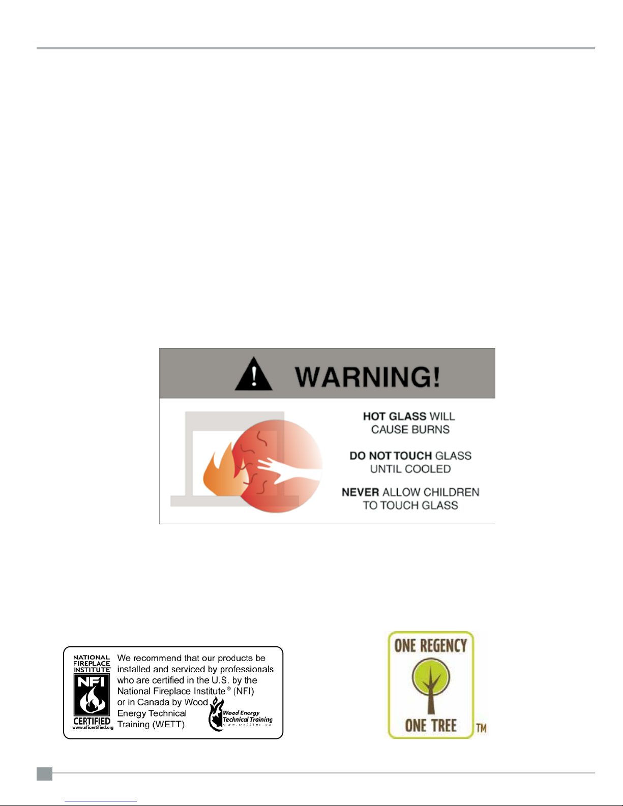
CAUTION
HOT WHILE IN OPERATION DO NOT TOUCH. KEEP CHILDREN,
CLOTHING AND FURNITURE AWAY. CONTACT MAY CAUSE
SKIN BURNS. READ NAMEPLATE AND INSTRUCTIONS.
CHAUD DURANT LE FONCTIONNEMENT. NE TOUCHEZ PAS.
ÉLOIGNEZ LES ENFANTS, LES VÊTEMENTS ET LES MEUBLES.
LE CONTACT PEUT CAUSER DES BRÛLURES DE LA PEAU.
LISEZ LA PLAQUE SIGNALÉTIQUE ET LES INSTRUCTIONS
ATTENTION
RÉDUIT)
D 762mm/30po
E 381mm/15po
F 483mm/19po
D 711mm/28po
E 254mm/10po
F 381mm/15po
D 711mm/28po
E 254mm/10po
F 381mm/15po
I 711mm/28po
J 330mm/13po
MADE IN CANADA
JAN FEB MAR APR MAY JUN JUL AUG SEPT OCT NOV DEC
DATE OF MANUFACTURE
2014 20162015
918-216c
4
Hampton H300 Cast Freestanding Woodstove
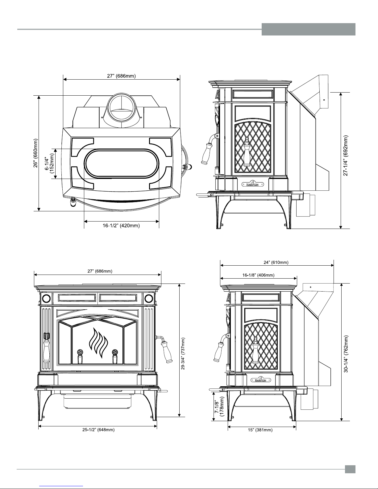
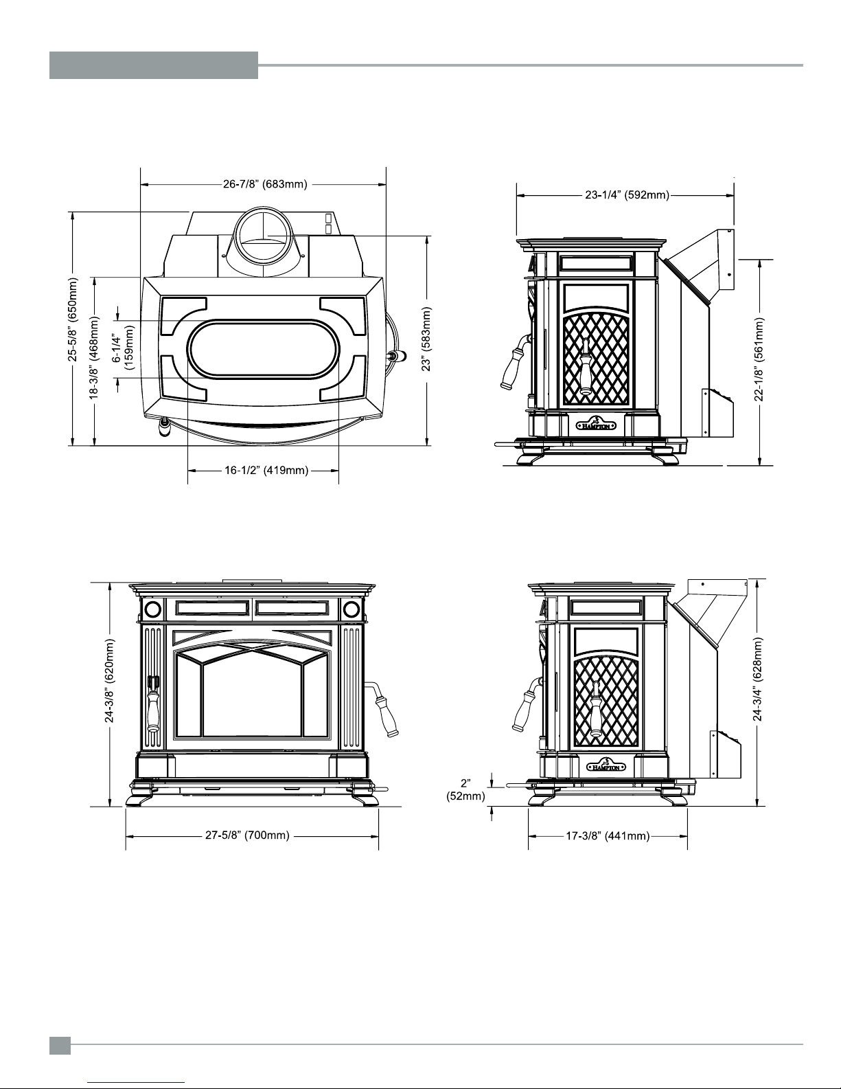
UNIT DIMENSIONS WITH STANDARD LEGS
DIMENSIONS
Hampton H300 Cast Freestanding Woodstove
5
DIMENSIONS
UNIT DIMENSIONS WITH OPTIONAL SHORT LEGS
6
Hampton H300 Cast Freestanding Woodstove
INSTALLATION
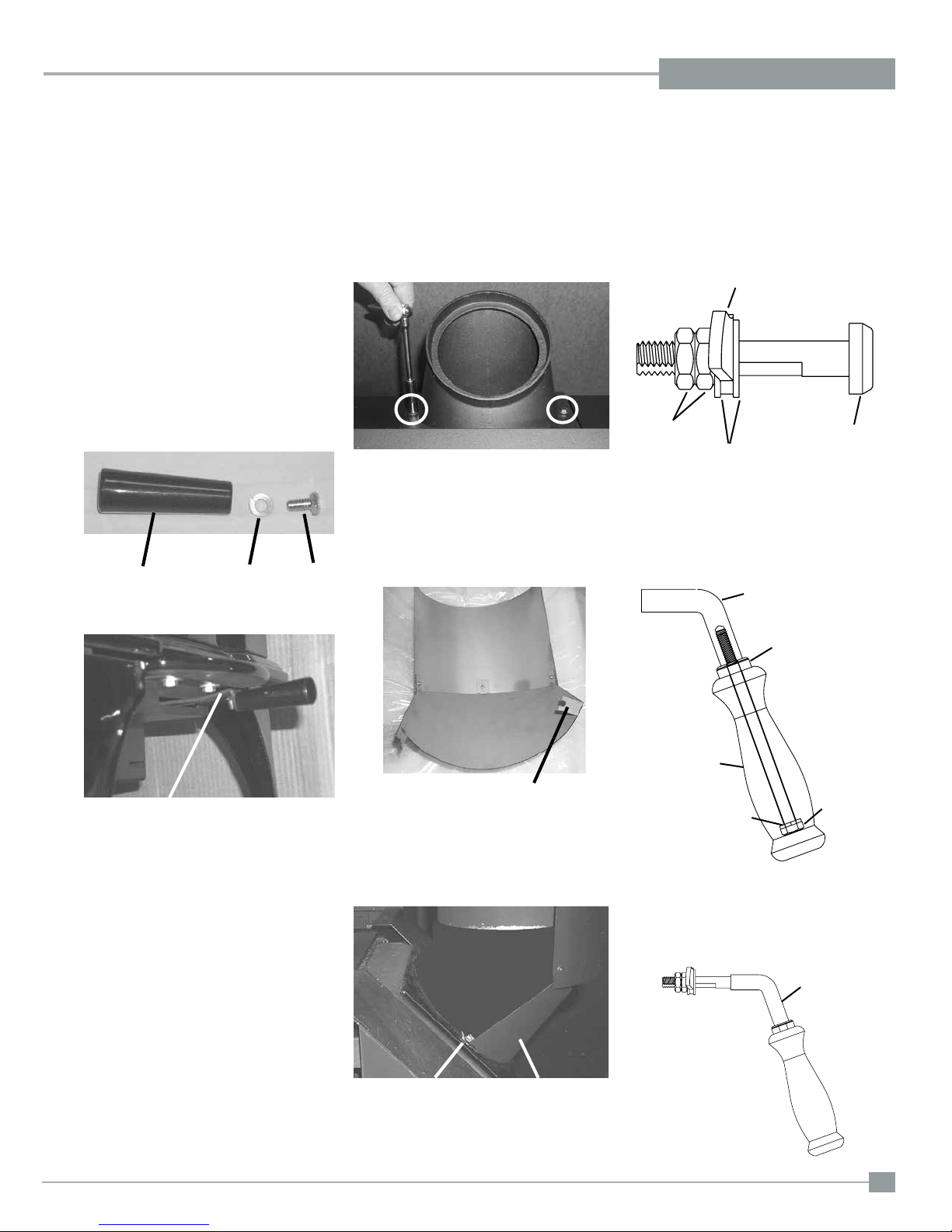
PRE-INSTALLATION
ASSEMBLY
After removing the stove from its packing, open
the front door and remove the contents from the
rebox, leaving the bricks in place.
Draft Control
Lever Handle
1) Insert bolt and lock washer through draft
control lever hole.
2) Place handle through bolt. Tighten to se-
cure.
Handle
Washer
Bolt
Rotating Elbow
This stove can be connected to either a top or
rear vent exit by simply reversing the orientation
of the elbow.
Simply remove the 2 screws, change the position of the elbow as desired and secure in place
with screws.
Rear Heat Shield
1) Loosen the bolts that secure the elbow to
the unit. Ensure elbow does not fall off.
2) Bend the tabs on the rear heat shield inwards
90 degrees.
Side Load
Door Handle
1) To install side door handle, remove side
door plug assembly.
Side Door Plug Assembly
Door Latch Bar
Hex Nuts
Flat Washers
2) Assemble handle by:
a) Placing lock washer over hex head bolt.
b) Place hex head bolt into handle.
c) Place spacer over hex head bolt
threads.
d) Screw handle into side door latch.
Latch
Side Door
Plug
Draft Control Lever
Bend tabs inwards 90 degrees.
3) Slide the tabs on the rear heat shield in
between the bolt and washer.
Please Note: The shield needs to be stretched/
exed in order to t in place.
Slide tabs in between
washer and bolt.
4) Once rear heat shield is evenly in place,
tighten bolts to secure.
Rear Heat Shield
Spacer
Handle
Lock
Washer
3) Place side door handle latch through side
door hole.
4) Re-assemble side door plug assembly to
secure.
Side Door
Plug Assembly
Hex Head
Bolt
Latch
Hampton H300 Cast Freestanding Woodstove
7
INSTALLATION
RESIDENTIAL
INSTALLATION
1) Please read this entire manual before you
install and use your new woodstove. Failure
to follow instructions may result in property
damage, bodily injury or even death. Be
aware that local Codes and Regulations
may override some items in this manual.
Check with your local inspector.
2) Select a position for your Hampton Stove.
Consult the minimum clearance chart for
your model and set the stove in place. For
close clearance installation use listed double
wall connector systems.
3) To insure vertical alignment, suspend a
plumb bob from the ceiling over the exact
center of your stove ue and mark a spot
on the ceiling to indicate the center of the
chimney.
4) Check that the area above the ceiling is
clear for cutting. Re-conrm the clearance
from the stove to combustibles to insure that
they are within the prescribed limits.
5) This woodstove must be connected to a
UL 103 HT (ULC S629) listed chimney or
a code approved masonry chimney with a
ue liner.
6) Install chimney according to chimney manu-
facturers instructions. The performance of
your woodstove is governed to a very large
part by the chimney system. Too short a
chimney can cause difcult start-up, dirty
glass, backsmoking when door is open, and
even reduced heat output. Too tall a chimney
may prompt excessive draft which can result
in very short burn times and excessive heat
output. The use of an inexpensive ue pipe
damper may be helpful in reducing excessive
draft.
CAUTION: The chimney should be the same
size as the 6" (152mm) ue outlet on the
stove. The chimney must be listed as suitable for use with solid fuels. For other types
of chimneys check with your local building
code ofcials. Do not confuse a chimney
with a type “B” Venting System used for gas
appliances as suitable for a wood burning
appliance (refer to the Mobile Home installations section).
7) Mark the location of the legs on the oor,
then move the stove aside and mark the
position of the oor protector.
8) The oor protector must be of non-combus-
tible material and must extend 18" (457mm)
in front of the door opening and 6" (152mm)
to the sides and rear of the unit. Some areas
may require a larger size oor protector.
Refer to the Mobile Home Installation section for outside air installation instructions
and see your local inspector.
NOTE: In Canada, oor protection must extend 18" (450mm) to the front and 8" (200mm)
to each side and back of the stove.
9) When the oor protection is complete, posi-
tion the stove with the ue collar centered
under the installed chimney.
10) In seismically active areas, we recommend
that your unit is secured to the oor by using
the bolt down holes inside the legs (the same
ones used in Mobile Home installations).
11) For residential installations using 6"
(152mm) "C" Vent (single wall) the chimney
connector must be at least 24 gauge steel.
Do not use galvanized pipe (refer to the
Mobile Home installation section).
12) Do not connect this unit to a chimney
serving another appliance.
13) A chimney connector cannot pass through
an attic or roof space, closet or similar
concealed space, or a oor, ceiling, wall
or partition of combustible construction.
In Canada, if passage through a wall, or
partition of combustible construction is
desired, the installation shall conform to
CAN/CSA-B365, Installation Code for SolidFuel-Burning Appliances and Equipment.
14) Your Hampton Woodstove is not to be connected to any air distribution duct.
Emissions from burning wood or gas could
contain chemicals known to the State of
California to cause cancer, birth defects
or other reproductive harm.
MODULAR INSTALLATION OPTIONS
OPTIONS: These can be installed at time of installation or added later:
Modular Option
Blower/Fan
Side Load Door
Outside Air
Adaptor
Side Shelves
Short legs
8
Adding the blower will increase the area heated by the stove, it can move warm air beyond the room where the stove
is installed (refer to the Optional Blower / Fan Installation section).
The side load door allows for putting in larger logs into the re easier ( refer to Side Load Door section).
Helps combustion in small or poorly ventilated houses. Installation instructions come with adaptor.
Add to the traditional look of the stove and double as a warming area for your cookstove creations.
Helps in reducing the overall height of the unit to accomodate a variety of installations. Using this option prohibits the
use of the ash drawer.
Things to consider when choosing options
Hampton H300 Cast Freestanding Woodstove
INSTALLATION
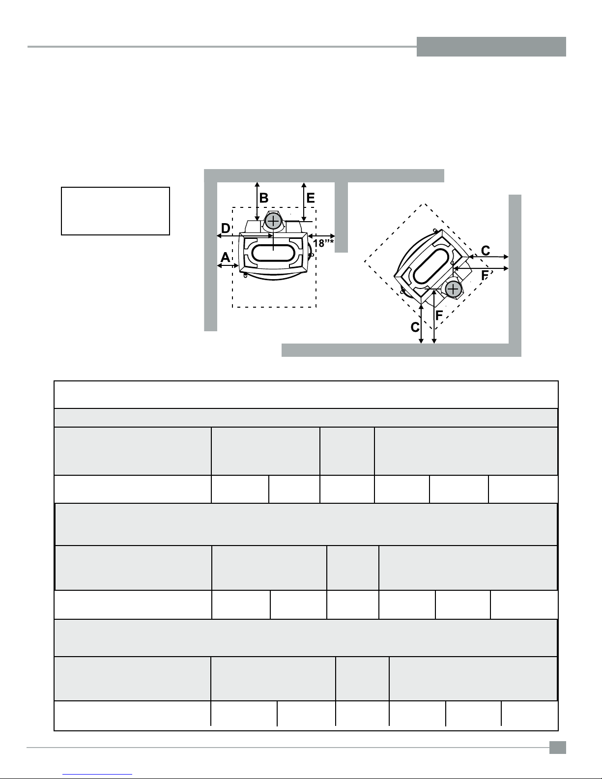
MINIMUM CLEARANCE AND CLEARANCE TO COMBUSTIBLE MATERIALS
Please read the section below carefully. Measurements "From Unit" are from the top plate of the stove to a side wall or to a corner, and from the
rear heat shield to a back wall.
Clearances may only be reduced by means approved by the regulatory authority.
* Minimum clearance with
side load door in use is 18"
(457mm) to side wall or refer
to dimension (A) if side load
door is not used.
NOTE: Be aware that local Codes and Regulations may override some clearances listed in this manual.
Check with your local inspector.
Residential Installation “C” Vent (Single Wall)
Unit (with Heat Shield) From Unit From From Flue Center-Line
Corner
A B C D E F
H300 17" (431 mm) 15" (381 mm) 13" (330 mm) 30" (762 mm) 15" (381 mm) 19" (483 mm)
Residential Close Clearance (To be installed with required pipe components)
When the stove is installed as a close clearance residential unit, a listed double wall connector is required from the stove collar to the ceiling
level.
Unit (with Heat Shield) From Unit From From Flue Center-Line
Corner
A B C D E F
H300 15" (381 mm) 10" (254 mm) 9" (228 mm) 28" (711 mm) 10" (254 mm) 15" (381 mm)
Mobile Home Close Clearance (To be installed with required pipe components)
"C" Vent single wall pipe is not approved for Mobile Home installations. (Refer to Mobile Home section).
Unit (with Heat Shield) From Unit From From Flue Center-Line
Corner
A B C D E F
H300 15" (381 mm) 10" (254 mm) 9" (228 mm) 28" (711 mm) 10" (254 mm) 15" (381 mm)
Hampton H300 Cast Freestanding Woodstove
9
INSTALLATION
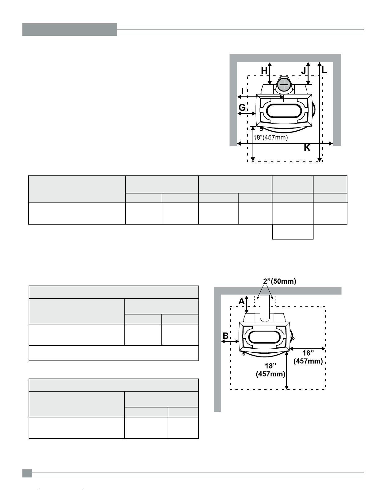
MINIMUM ALCOVE CLEARANCE TO
COMBUSTIBLE MATERIALS
This Hampton Freestanding model has been alcove approved and must be installed
with a listed double wall connector to the ceiling level.
Note: Minimum alcove ceiling height (from nished oor) - 60" (1525 mm)
Maximum depth of alcove - 48" (1220 mm)
From From Flue Min. Min.Hearth
Unit (with Heat Shield) Unit Center-line Width to Rear Wall
G H I J K L
H300 15" (381 mm) 13" (330 mm) 28" (711 mm) 13" (330 mm) 57" (1448 mm) 51-1/4"
without side load door (1301 mm)
60" (1524 mm)
with side load door
ADDITIONAL CLEARANCES
FOR BACKWALL EXIT
Minimum Clearance to Combustibles
From
Unit (with Heat Shield) Unit
A B
H300 9" (228 mm) 15" (381 mm)
Min. Mantel Height (from nished oor): 48" 1219 mm
Max. Mantel Depth: 12" 305 mm
Minimum Clearance to Non-Combustibles
From
Unit (with Heat Shield) Unit
A B
H300 min. 0" (0 mm) 15" (381mm)
max. 9" (228 mm)
10
Note: Floor Protection must extend 2" (50mm)
to each side of the elbow.
Note: If side load door is used, oor protection
must extend at least 18" (457mm) from
the side of the unit.
Hampton H300 Cast Freestanding Woodstove
INSTALLATION
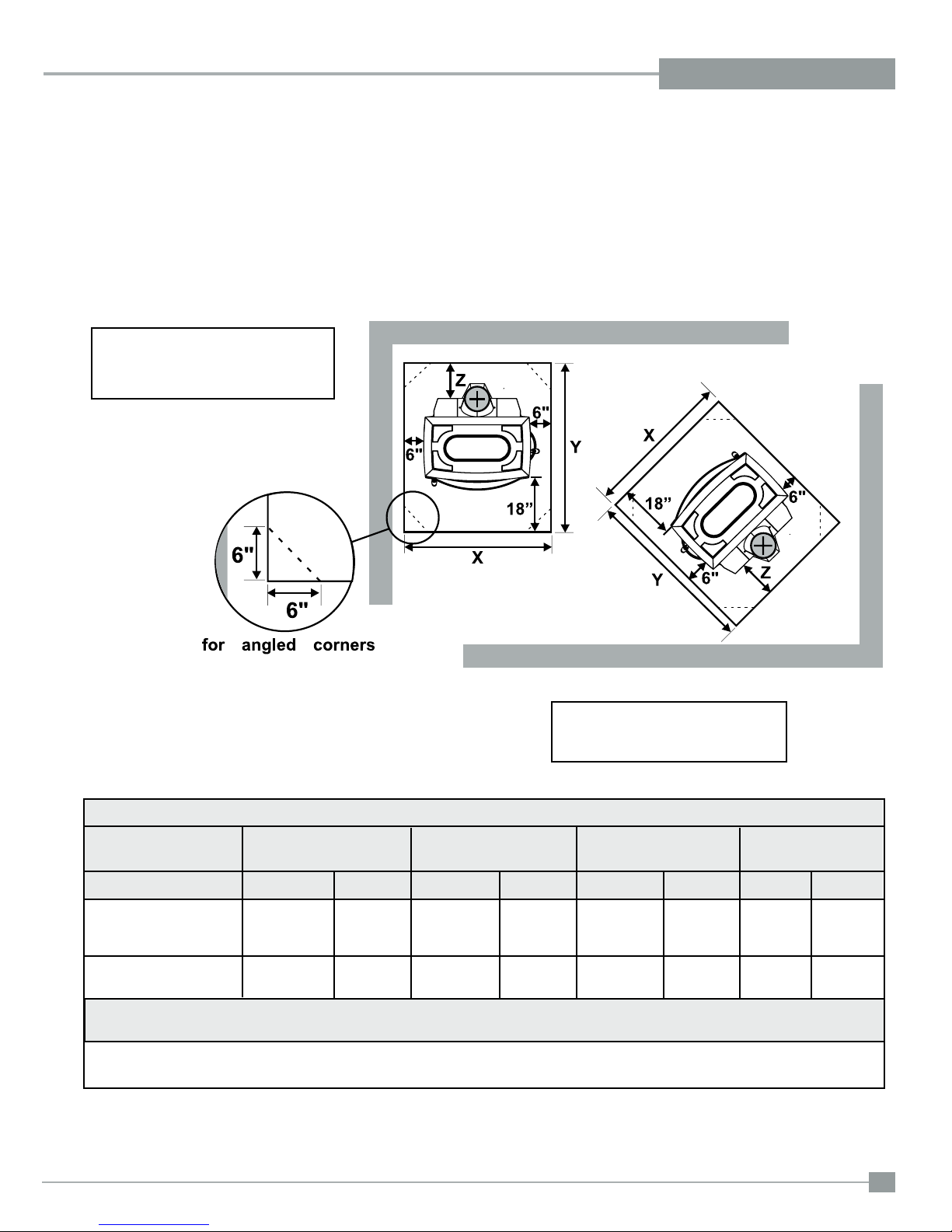
FLOOR PROTECTION
A combustible oor must be protected by non-combustible material (like tile, concrete board, or certied to UL-1618 or as dened by local codes)
extending beneath the heater and a minimum of 6" from each side and minimum 18" from the front face of the stove and minimum 6" (or the rear
clearance to combustibles whichever is smaller) from the rear of the stove.
When installed with horizontal venting, non-combustible oor protection must beneath the ue pipe and extend 2" (51mm) beyond each side.
A minimum of a 3/8" thick thermal oor protector with a 0.84k factor is required when installing the standard or optional short legs. This applies to
both Canada and the US. All other requirements (ie. hearth size) remain the same.
IF SIDE LOAD DOOR IS USED:
Floor protection must extend 18" (457mm)
from the side of the unit to the wall.
NOTE: In Canada, oor protection must
extend 18" (450mm) to the front
and 8" (200mm) to each side and
back of the stove.
Minimum Overall Depth (Y) of Floor Protector
Residential Residential Mobile Home Alcove
Unit "C" Vent Close Clearance Close Clearance
Y Z Y Z Y Z Y Z
H300 (US) 44-1/2" 6" (152 mm) 44-1/2" 6" (152 mm) 44-1/2" 6" (152 mm) 44-1/2" 6" (152 mm)
(1130 mm) (1130 mm) (1130 mm) (1130 mm)
H300 (Canada) 46-1/2" 8" (203 mm) 46-1/2" 8" (203 mm) 46-1/2" 8" (203 mm) 46-1/2" 8" (203 mm)
(1181 mm) (1181 mm) (1181 mm) (1181 mm)
Minimum Overall Width (X) of Floor Protector for all installations:
H300 39" (990 mm) - US
43" (1092mm) - Canada
Hampton H300 Cast Freestanding Woodstove
11
 Loading...