

HAMPTON BAY Hampton H25-NG, H25-LP, H25 Owners & Installation Manual
www.hampton-fire.com
H25 Direct Vent Gas Fireplace
Owners &
Installation Manual
MODELS: H25-NG Natural Gas H25-LP Propane
WARNING:
If the information in these instructions are not
followed exactly, a fire or explosion may result
causing property damage, personal injury or loss
of life.
FOR YOUR SAFETY
Do not store or use gasoline or other flammable
vapours and liquids in the vicinity of this or any
other appliance.
Installation and service must be performed by a
qualified installer, service agency or the gas
supplier.
Tested by:
Homeowner: Please keep these instructions for future reference.
918-101b
FPI FIREPLACE PRODUCTS INTERNATIONAL LTD. 6988 Venture St., Delta, BC Canada, V4G 1H4
FOR YOUR SAFETY
What to do if you smell gas:
Do not try to light any appliance
Do not touch any electrical switch:
do not use any phone in your
building.
Immediately call your gas supplier
from a neighbour's phone. Follow
the gas supplier's instructions.
If you cannot reach your gas
supplier, call the fire department.
Installer: Please complete the details on the back cover
and leave this manual with the homeowner.
This appliance may only be
installed in an aftermarket permanently located, manufactured (USA only) or mobile
home, where not prohibited
by local codes.
This appliance is only for use
with the type of gas indicated
on the rating plate. This appliance is not convertible for use
with other gases, unless a certified kit is used.
01/09/06
HAMPTON
Direct Vent Freestanding Gas Stove
To the New Owner:
Congratulations!
You are the owner of a state-of-the-art Hampton Gas Stove by FPI FIREPLACE PRODUCTS INTERNATIONAL LTD .
The H25 is a hand crafted appliance and has been designed to provide you with all the warmth and charm of a wood
fireplace at the flick of a switch. The model H25 has been approved by Warnock Hersey for both safety and efficiency.
As it also bears our own mark, it promises to provide you with economy, comfort and security for many trouble free
years to follow. Please take a moment now to acquaint yourself with these instructions and the many features of your
Hampton Stove.
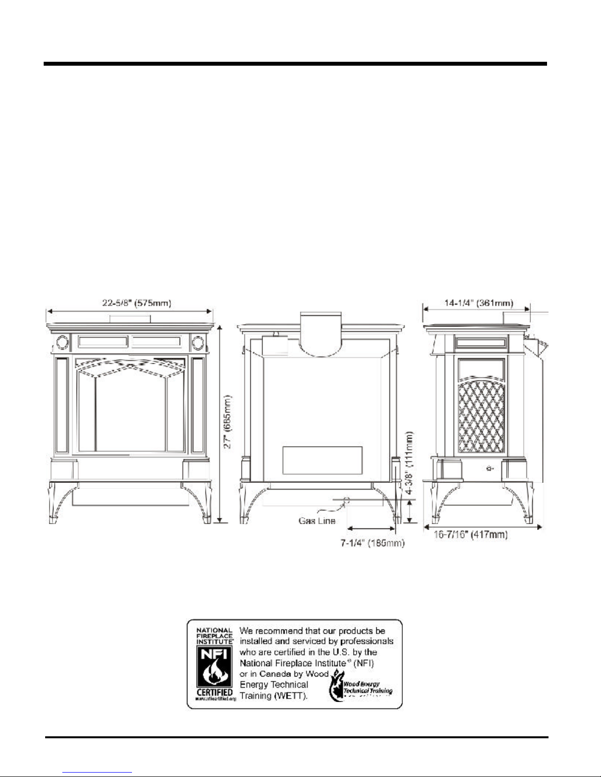
UNIT DIMENSIONS
2
Hampton H25 Direct Vent Freestanding Gas Stove

TABLE OF CONTENTS
Page Page
Safety Label
Safety Labels ......................................................... 4
Installation
Specifications .......................................................... 5
Information for Mobile/Manufactured Home
After First Sale .................................................. 5
Before You Start ...................................................... 5
General Safety Information ........................................ 6
Installation Checklist ................................................ 6
Clearances to Combustibles ..................................... 6
Locating Your Gas Stove ......................................... 7
Manufactured Mobile Home Requirements.................. 7
Combustion and Ventilation Air ................................. 7
Optional Fan Installation ........................................... 7
Venting Introduction ................................................. 9
Installation Precautions ............................................ 9
Safety Precautions for the Installer ............................ 9
Vent Restrictor Position............................................ 9
Rotating 45 degree Elbow ......................................... 9
Exterior Vent Terminal Locations .............................. 10
Rigid Pipe Venting Components List ......................... 11
Rigid Pipe Venting Systems
Horizontal or Vertical Terminations ..................... 12
Venting Arrangements - Horizontal Terminations ........ 13
Venting Arrangements - Vertical Terminations ........... 13
Horizontal Venting With Two Elbows ......................... 14
Vertical Venting With Two Elbows ............................ 15
Vertical Termination with Co-linear Flex system ......... 16
Horizontal Termination Kit ........................................ 17
Horizontal Termination Kit Installation ...........................17
Residential and Manufactured Homes / Mobile Homes
Minimum horizontal termination Installations ..............19
Dura-Vent Termination Kits ......................................................20
Planning Your Dura-Vent Installation .....................................20
Minimum Dura-Vent Components - Horizontal
Installation........................................................ 20
Minimum Dura-Vent Components - Vertical
Termination ...................................................... 20
Dura-Vent Venting Components Parts List ................ 21
Dura-Vent Horizontal Installation............................... 21
Dura-Vent Vertical Termination Installation ................ 22
Offset Chart ............................................................ 23
Converting a Class-A Metal Chimney or Masonry
Chimney to a Direct Vent System ............................ 24
Cathedral Ceiling Installations .................................. 25
Support Extension - Round or Square ....................... 25
High Elevation......................................................... 25
Gas Connection ...................................................... 25
System Data Chart ................................................. 25
Aeration Adjustment ................................................ 25
Gas Pipe Pressure Testing ...................................... 26
Valve Description .................................................... 26
Conversion to Propane............................................. 26
Log Installation ....................................................... 28
Optional Door Grill................................................... 30
Optional Wall Thermostat ........................................ 30
Optional Remote Control Installation ......................... 30
Final Check ............................................................ 31
Wiring Diagram ....................................................... 31
Operating Instructions
Operating Instructions ............................................. 32
Lighting Procedure .................................................. 32
Shutdown Procedure ............................................... 32
First Fire ................................................................ 32
Adjusting Flame Height ........................................... 32
Convection Fan Operation ........................................ 32
Copy of Lighting Plate Instructions ............................ 33
Normal Operating Sounds of
Gas Appliances ................................................ 34
Maintenance
Maintenance Instructions ......................................... 34
General Vent Maintenance .......................................35
Log Replacement .................................................... 35
Glass Replacement ................................................. 35
Fan Maintenance .................................................... 35
Removing and Installing Valve .................................. 36
Parts List
Replacement Parts List ........................................... 37
Warranty
Warranty ................................................................ 39
Hampton H25 Direct Vent Freestanding Gas Stove
3
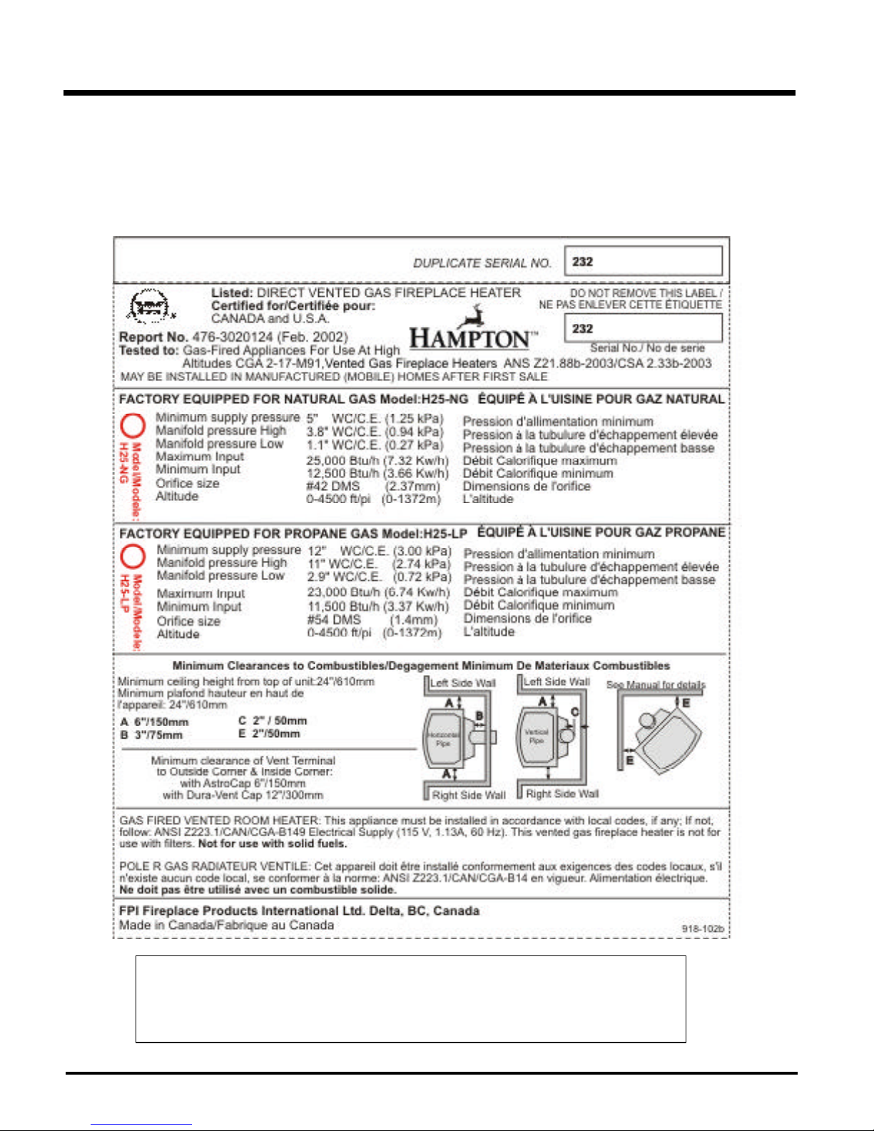
SAFETY LABEL
This is a copy of the label that accompanies
each Direct Vent Freestanding Gas Stove. We
have printed a copy of the contents here for
your review.
NOTE: Hampton units are constantly being
improved. Check the label on the unit and if there
is a difference, the label on the unit is the correct
one.
Copy of Safety Label for H25-NG & H25-LP
For the State of Massachusetts, installation and repair must be done by a plumber or gasfitter licensed in the
Commonwealth of Massachusetts.
For the State of Massachusetts, flexible connectors shall not exceed 36 inches in length.
For the State of Massachusetts, the appliances individual manual shut-off must be a t-handle type valve.
4
Hampton H25 Direct Vent Freestanding Gas Stove
INSTALLATION
IMPORTANT:
SAVE THESE
INSTRUCTIONS
The Direct Vent Freestanding Gas Stove must
be installed in accordance with these instructions. Carefully read all the instructions in this
manual first. Consult the building authority having jurisdiction to determine the need for a
permit prior to starting the installation.
Note: Failure to follow the instructions
could cause a malfunction of the
heater which could result in death,
serious bodily injury, and/or property damage. Failure to follow
these instructions may also void
your fire insurance and/or warranty.
Note: These instructions take prece-
dence over Simpson Dura-Vent
instructions.
SPECIFICATIONS
Fuels: H25-NG is approved for use with
natural gas.
H25-LP is approved for use with
liquefied petroleum gases (propane).
Electrical: 120V A.C. system.
Optional Circulation Fan:
Variable speed, 125/75.
501A, and with CAN/CSA Z240-MH Mobile
Home Standard in Canada.
This appliance installation must comply with the
manufacturer's installation instructions and local codes, if any. In the absence of local codes
follow the current National Fuel Gas Code, ANSI
Z223.1 and the current National Electrical Code
ANSI/NFPA 70 in the U.S.A., and the current
CAN/CGA B149 Gas Installation Code and the
current Canadian Electrical Code CSA C22.1 in
Canada.
This Hampton Mobile/Manufactured
Home Listed appliance comes factory
equipped with a means to secure the
unit.
This Hampton Mobile/Manufactured
Home listed appliance comes
equipped with a dedicated #8 ground
lug to which an 18 gauge copper wire
from the steel chassis ground must be
attached.
This appliance may only be installed in
an aftermarket permanently located,
manufactured (USA only) or mobile
home, where not prohibited by local
codes.
This appliance is only for use with the
type of gas indicated on the rating
plate. This appliance is not convertible for use with other gases, unless a
certified kit is used.
DUE TO HIGH TEMPERATURES,
THE APPLIANCE SHOULD BE LOCATED OUT OF TRAFFIC AND
AWAY FROM FURNITURE AND
DRAPERIES.
WARNING: FAILURE TO INSTALL
THIS APPLIANCE CORRECTLY
WILL VOID YOUR WARRANTY AND
MAY CAUSE A SERIOUS HOUSE
FIRE.
CHILDREN AND ADULTS SHOULD
BE ALERTED TO THE HAZARDS
OF HIGH SURFACE TEMPERATURES, ESPECIALLY THE FIREPLACE GLASS, AND SHOULD
STAY AWAY TO AVOID BURNS
OR CLOTHING IGNITION.
YOUNG CHILDREN SHOULD BE
CAREFULLY SUPERVISED WHEN
THEY ARE IN THE SAME ROOM AS
THE APPLIANCE.
CLOTHING OR OTHER FLAMMABLE MATERIAL SHOULD NOT BE
PLACED ON OR NEAR THE APPLIANCE.
1) Provide adequate clearances for servic-
ing, proper operation and around the air
openings into the combustion chamber.
Log Sets: Ceramic fibre, 4 per set.
Vent System: Coaxial (6-5/8" outer / 4" inner
liner) rigid flue and termination cap.
INFORMATION FOR
MOBILE/
MANUFACTURED
HOMES AFTER
FIRST SALE
This Hampton product has been tested and
listed by ITS Testing Services as a Direct Vent
Wall Furnace to the following standards:
CGA-2.17-M91, and ANS Z21.88b-2003/CSA
2.33b-2003.
This Direct Vent System Appliance must be
installed in accordance with the manufacturer's installation instructions and the Manufactured Home Construction and Safety Standard,
Title 24 CFR, Part 3280, or the current Standard
of Fire Safety Criteria for Manufactured Home
Installations, Sites, and Communities ANSI/NFPA
Hampton H25 Direct Vent Freestanding Gas Stove
BEFORE YOU START
Safe installation and operation of this appliance
requires common sense, however, we are
required by the Canadian Safety Standards
and ANSI Standards to make you aware of the
following:
INSTALLATION AND REPAIRS
SHOULD BE DONE BY A QUALIFIED SERVICE PERSON. THIS APPLIANCE SHOULD BE INSTALLED,
REPAIRED, INSPECTED BEFORE
USE AND AT LEAST ANNUALLY
BY A QUALIFIED SERVICE PERSON. MORE FREQUENT CLEANING MAY BE REQUIRED DUE TO
EXCESSIVE LINT FROM CARPETING, ETC. IT IS IMPERATIVE THAT
THE CONTROL COMPARTMENT,
BURNERS AND CIRCULATING AIR
PASSAGEWAYS OF THE APPLIANCE BE KEPT CLEAN.
2) The appliance must be installed on a flat,
solid, continuous surface (e.g. wood, metal, concrete). This may be the floor, or it can
be raised up on a platform to enhance its
visual impact. The appliance may be installed on carpeting, tile, wood flooring or
other combustible material, because the
appliance's base extends the full width and
depth of the appliance. The Direct Vent
Freestanding Gas Stove can be installed in
a wide variety of ways and will fit nearly
any room layout. It may be installed in a
recessed position, framed out into the room,
or across a corner.
3) The Direct Vent Freestanding Gas Stove is
approved for alcove installations, which
meet the clearances listed on page 6. This
unit is approved for manufactured home
installations, see page 7 and pages 13 to 16
for the required vent arrangements. If installed into a manufactured home the unit
must be bolted down to the floor.
4) This appliance is Listed for bedroom installations when used with a Listed Millivolt
Thermostat. Some areas may have further
requirements, check local codes before
installation.
5
INSTALLATION
5) This appliance is Listed for Alcove installa-
tions, maintain minimum Alcove clearances
as follows, minimum width of 34-3/4"
(882mm), a maximum depth of 36" (914mm),
and minimum ceiling height of 51" (1295mm)
from floor to ceiling.
6) We recommend that you plan your installation on paper using exact measurements
for clearances and floor protection before
actually installing this appliance. Have a
qualified building inspector review your
plans before installation.
GENERAL SAFETY
INFORMATION
1) The appliance installation must conform
with local Canadian Electrical Code.
2) The appliance when installed, must be electrically grounded in accordance with local
codes, or in the absence of local codes with
the current National Electrical Code, ANSI/
NFPA 70 or CSA C22.1 Canadian Electrical
Code.
3) The appliance should be inspected for
shipping damage before use and serviced
annually by a professional service person. More frequent cleaning may be re-
quired due to excessive lint from carpeting,
bedding material, etc. It is imperative that
control compartments, and circulating air
passageways of the appliance be kept
clean and free from excessive lint from
carpeting.
4) See general construction and assembly
instructions. The appliance and vent should
be enclosed when installed in or passing
through a living area, where children may
come in contact with it.
9) To prevent injury, do not allow anyone who
is unfamiliar with the operation to use the
fireplace.
Emissions from burning wood or gas could
contain chemicals known to the State of
California to cause cancer, birth defects or
other reproductive harm.
INSTALLATION
CHECKLIST
1) Check Clearances to Combustibles (page
6), location of unit (page 7) and venting
requirements (pages 9-12).
2) Install Optional Fan, see page 7.
3) Set vent restrictor, page 9.
4) Install venting: Check all venting require-
ments, pages 9-13. Vertical Termination
with Co-linear Flex System, page 16. Horizontal Termination Kits, page 17. Minimum
Horizontal Termination, page 19. Dura-Vent
Termination Kits, page 20.
5) Make gas connections, page 25. Test the
pilot. Must be as per diagram, page 32.
If converting to Propane, make changes
prior see pages 26.
6) Test Gas Pressure, page 26.
7) Install logs and embers where indicated on
page 28.
8) Install optional Remote Control, or Wall Thermostat, page 30.
9) Final check, page 31.
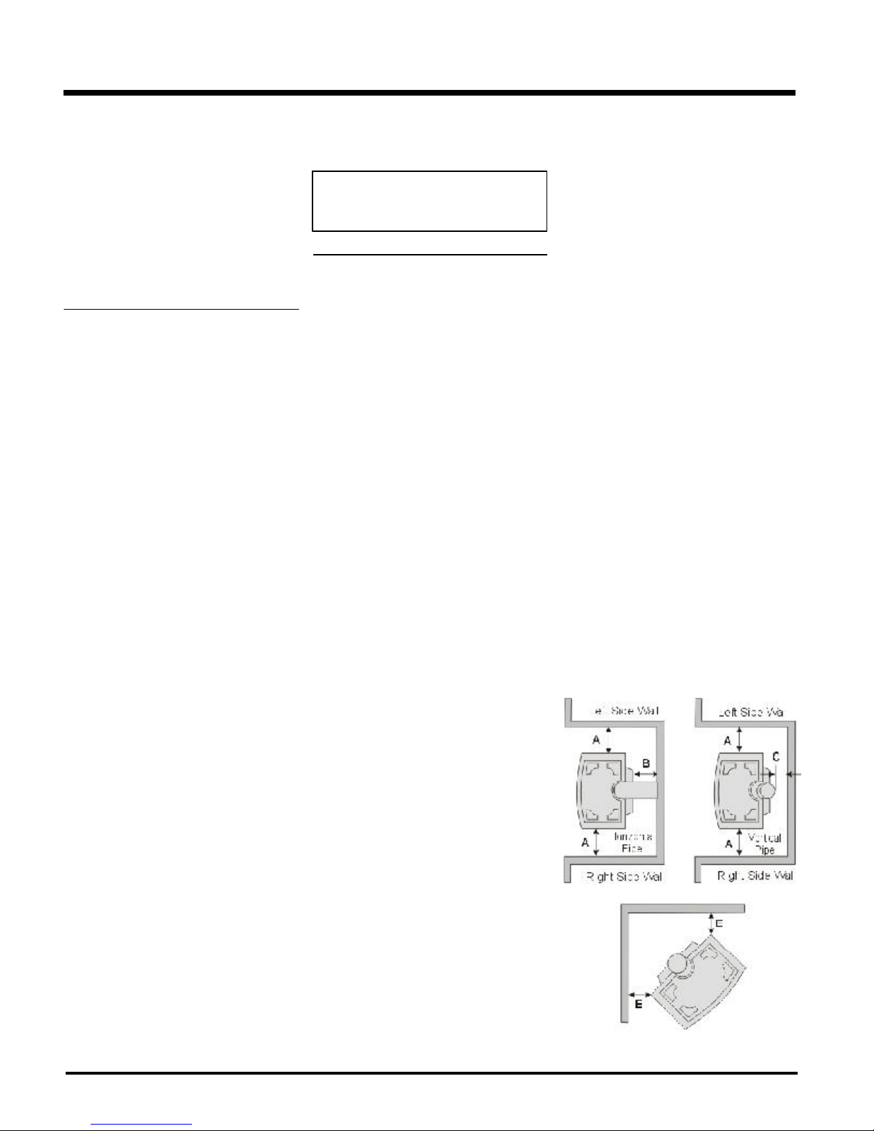
CLEARANCES TO
COMBUSTIBLES
The clearances listed are MINIMUM distances.
Measure the clearance to both the appliance
and the chimney connector. The farthest
distance is correct if the two clearances
do not coincide.
For example, if the appliance is set as indicated
in one of the figures but the connector is too
close, move the stove until the correct clearance to the connector is obtained.
This appliance may be installed only with the
clearances as shown in the situations pictured.
Do not combine clearances from one
type of installation with another in order
to achieve closer clearances.
This unit can be installed on a solid combustible
surface like a wood floor. This unit can also be
installed directly on carpeting or vinyl.
Use the minimum clearances shown in the
diagrams below:
H25-NG & H25-LP Clearances
A Left Side Wall to Unit* 6" / 150 mm
B Back Wall to Unit 3" / 75 mm
C Vertical Vent Pipe to Back Wall
2" / 50 mm
E Unit Corner to Wall 2" /50 mm
Unit Top to Alcove Ceiling 24" / 610 mm
Minimum ceiling height is 24" /610 mm from top
of unit.
5) This appliance must be connected to the
specified vent and termination cap to the
outside of the building envelope. Never vent to another room or inside a building.
Make sure that the vent is fitted as per the
instructions starting on page 10.
6) Inspect the venting system annually for
blockage and any signs of deterioration.
7) Venting terminals shall not be recessed into
a wall or siding.
8) Any safety glass removed for servicing
must be replaced prior to operating the
appliance.
6
Before leaving this unit with the customer, the
installer must ensure that the appliance is firing
correctly and operation fully explained to
customer.
This includes:
1) Clocking the appliance to ensure the cor-
rect firing rate (rate noted on label) after
burning appliance for 15 minutes.
2) If required, adjusting the primary air to
ensure that the flame does not carbon. First
allow the unit to burn for 15-20 min. to
stabilize.
CAUTION: Any alteration to the product
that causes sooting or carboning that
results in damage is not the responsibility of the manufacturer.
Hampton H25 Direct Vent Freestanding Gas Stove
INSTALLATION
LOCATING YOUR
GAS STOVE
When selecting a location for your stove, ensure that the clearances listed above are met as
well as ensuring that there is adequate accessibility for servicing and proper operation.
A) Cross Corner
B) Room Divider
C) Island
D) Flat on Wall
E) Flat on Wall Corner
F) Flush with Wall/Alcove
For Vent Termination requirements,
see page 10.
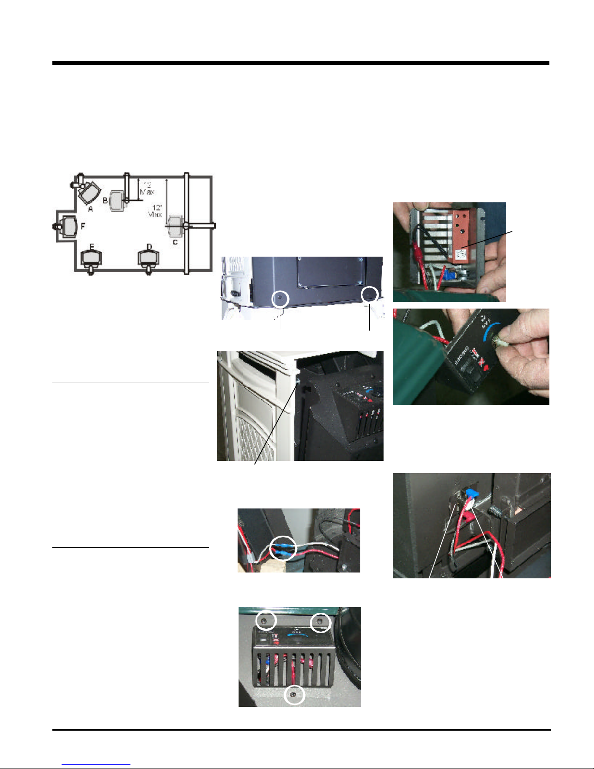
OPTIONAL FAN
INSTALLATION
Fan Kit Contains:
Qty. Description
1 Fan Assembly c/w green wire attached
1 Thermodisc
1 power cord
2 2-1/4" x 20 hex nut
1 Fan Speed Control
2) Remove the rear access panel on the back
of the stove by removing the 2 screws
under the rear panel, then lift off the 2
screws at the top. Take care not to cut
wires when lowering the panel.
screw
screw
4) Remove the nylon hole plug from the control
panel.
5) Install the fan speed controller onto the
control panel and secure with nut and
washer. Connect the red and black wires
from the wire harness to speed controller.
NOTE: Speed control wires must be in
the down position when control panel is in place.
6) Push black knob onto speed control.
Fan Speed
Controller
MANUFACTURED
MOBILE HOME
ADDITIONAL
REQUIREMENTS
1) Ensure that structural members are not cut
or weakened during installation.
2) Ensure proper grounding using the #8
ground lug provided.
3) Appliance must be anchored to the floor
with the supplied anchoring methods.
COMBUSTION AND
VENTILATION AIR
The combustion air from this appliance is drawn
from outside the building through the outer flue.
Extra provision for combustion air inside
the room is not required.
screw
Lift Rear Panel off the 2 top screws
2) Disconnect the red and grey wires.
3) Remove the Top Control Panel Assembly by
removing the three screws.
7) Re-attach control panel with 3 screws,
reversing step 3.
8) Slide Thermodisc into the bracket on the left
side of the rear firebox.
Thermodisc
Braket
Thermodisc
Hampton H25 Direct Vent Freestanding Gas Stove
Top Control Panel Assembly
7
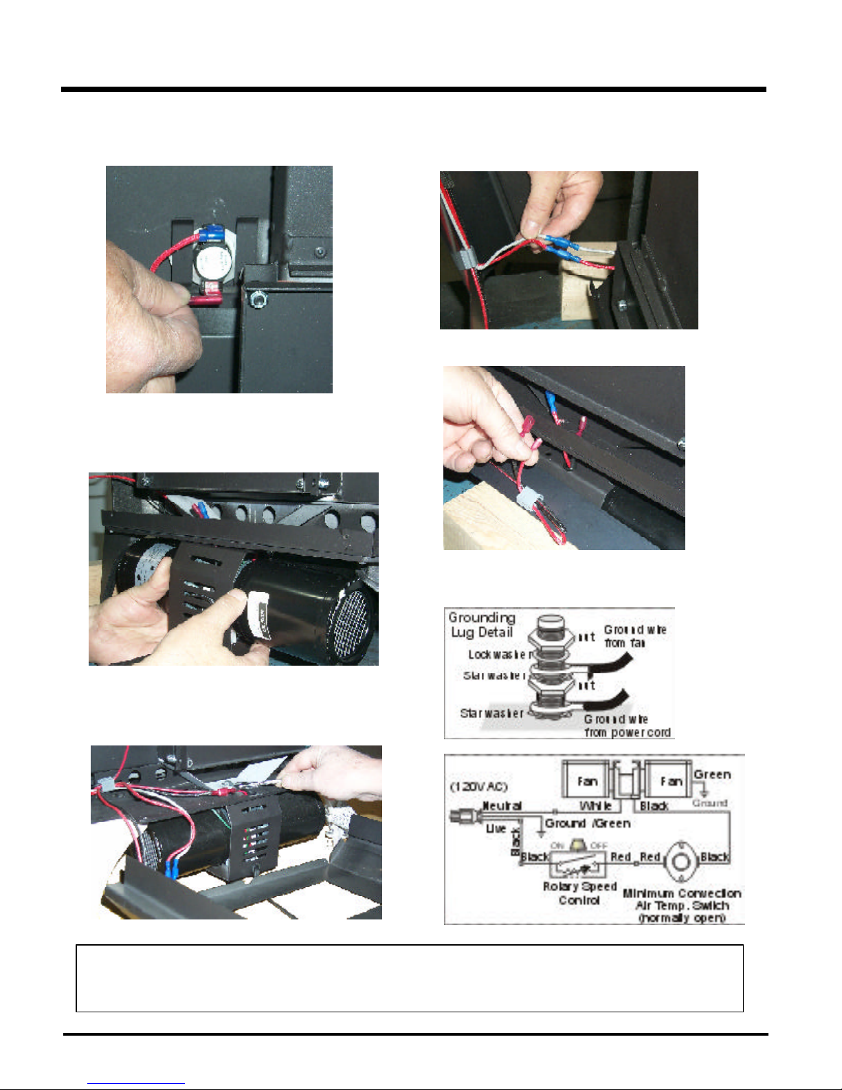
INSTALLATION
9) Place the blower close to the base of the unit and feed the long red
and black wires through the opening of the base of the unit and
connect them to the thermodisc.
10)Feed the short red and black wires through the small hole at the base
of the unit.
12)Before re-attaching the rear access panel, the valve wires and the
fan wires need to be connected.
Re-connect the red and grey valve wires.
Connect the fan wires.
13)Slide the Rear Access Panel back into position and secure with 2
screws.
11)Mount the blower assembly in position under the base of the stove
and secure with the 2 supplied bolts (2-1/4" #20 hex head)
This appliance is equipped with a three pronged (grounding) plug for your protection against shock hazard and should
be plugged directly into a properly grounded three-prong receptacle. Do not cut or remove the grounding prong from
this plug.
WARNING: Electrical Grounding Instructions
8
Hampton H25 Direct Vent Freestanding Gas Stove
INSTALLATION
VENTING
INTRODUCTION
The Horizontal Termination Kit and the Simpson
Dura-Vent Direct Vent System Model DV-GS
venting systems, in combination with the Direct
Vent Freestanding Gas Stoves, H25-NG, and
H25-LP , have been tested and listed as direct
vent heater systems by Warnock Hersey.
These units use the "balanced flue" technology Co-Axial system. The inner liner vents
products of combustion to the outside while the
outer pipe draws outside combustion air into
the combustion chamber thereby eliminating
the need to use heated room air for combustion
and losing warm room air up the chimney.
Note: These flue pipes must not be
connected to any other appliance.
The gas appliance and vent system must be
vented directly to the outside of the building,
and never be attached to a chimney serving a
separate solid fuel or gas burning appliance.
Each direct vent gas appliance must use it's
own separate vent system. Common vent systems are prohibited.
IMPORTANT
INSTALLATION
PRECAUTIONS
These venting systems are engineered products that have been designed and tested for
use with the H25-NG, and H25-LP . The warranty will be voided and serious fire, health or other
safety hazards may result from any of the
following actions:
1) Installation of any damaged Direct Vent
component
2) Unauthorized modification of the Direct Vent
System
3) Installation of any component part not manufactured or approved by Simpson DuraVent or FPI Fireplace Products International
Ltd.
4) Installation other than as instructed by Simpson Dura-Vent and FPI Fireplace Products
International Ltd.
Warning: Always maintain required
clearances (air spaces) to nearby
combustibles to prevent a fire hazard. Do not fill air spaces with insulation.
SAFETY
PRECAUTIONS FOR
THE INSTALLER
1) Wear gloves and safety glasses for pro-
tection.
2) Exercise extreme caution when using ladders or on roof tops.
3) Be aware of electrical wiring locations in
walls and ceilings.
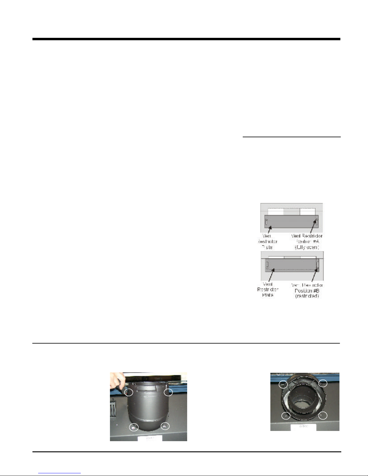
VENT RESTRICTOR
POSITION
To set the Vent restriction as indicated in the
Venting Arrangement diagrams on page 13-16,
simply loosen the screws and push the vent
restrictor plate to the correct position. Tighten
the screws.
Read all instructions carefully before starting
the installation. Failure to follow these instructions may create a fire or other safety hazard,
and will void the warranty. Be sure to check the
venting and clearance to combustible requirements. Consult your local building codes before
beginning installation.
The location of the termination cap must conform to the requirements in the Exterior Vent
Terminal Locations on page 10.
1) Remove all 4 screws that secure
the elbow to the unit using a 1/4"
magnetic nut driver.
Remove all 4 screws
and washers
Be sure to check the vent termination clearance
requirements from decks, windows, soffits,
gas regulators, air supply inlets and public
walkways as specified in the Exterior Vent
Terminal Locations on page 10 and in your local
building codes.
The gas appliance and vent system must
be vented directly to the outside of the
building, and never be attached to a chimney serving a separate solid fuel or gasburning appliance. Each direct vent gas
appliance must use it's own separate vent
system. Common vent systems are prohibited.
ROTATING 45O ELBOW
2) Rotate the elbow 180
3) Secure the elbow by securing
it with the 4 screws.
o
Hampton H25 Direct Vent Freestanding Gas Stove
9
INSTALLATION
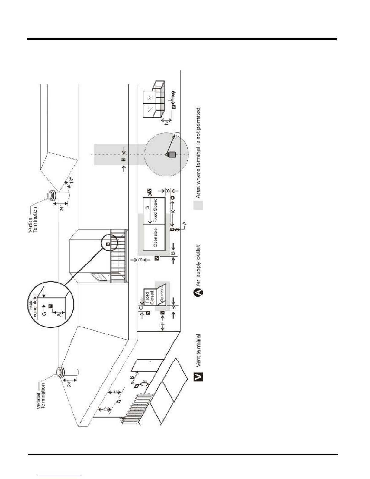
EXTERIOR VENT TERMINAL LOCATIONS
any other appliance *(12"/30cm)
*(min. 84"/2.1m)
J= Clearance to service regulator vent outlet *(min. 36"/90cm)
K= Clearance to non-mechanical air supply inlet to building or the combustion air inlet to
L= Clearance to a mechanical air supply inlet *(min. 72"/1.8m)
M= **Clearance above paved sidewalk or a paved driveway located on public property
N= Clearance under veranda, porch, deck, or balcony *(min. 12"/30cm)***
Note: * As specified in CGA B149 Installation Code. Note: Local codes or regulations may
require different clearances.
**A vent shall not terminate directly above a sidewalk or paved driveway which is located
between two single family dwellings and serves both dwellings.
***Only permitted if veranda, porch, deck, or balcony is fully open on a minimum of two
sides beneath the floor.
10
distance of (24"/60cm) from the centerline of the terminal (min. 22"/55cm) check with
local code.
Vent Termination Cap (min.12"/30cm), with Riser Vent (min. 6"/15cm)
Vent Termination Cap (min.12"/30cm), with Riser Vent (min. 6"/15cm)
the centerline of the regulator.
A= Clearance above grade, veranda, porch, deck, or balcony *(min. 12"/30cm)
B= Clearance to window or door that may be opened *(12"/30cm)
C= Clearance to permanently closed window *(min. 12"/30cm)
D= Vertical clearance to ventilated soffit located above the terminal within a horizontal
E= Clearance to unventilated soffit (min. 12"/30cm)
F= Clearance to outside corner: with AstroCap Termination Cap (min. 6"/15cm), with Dura-
G= Clearance to inside corner: with AstroCap Termination Cap (min. 6"/15cm), with Dura-
H= Not to be installed above a meter/regulator assembly within (3'/90cm) horizontally from
Hampton H25 Direct Vent Freestanding Gas Stove
INSTALLATION
RIGID PIPE VENTING COMPONENTS LIST
All Simpson Dura-Vent components are available directly from FPI.
Description Simpson Dura-Vent Selkirk Amerivent
Direct VentGS
6" Pipe Length, Galvanized 908 4DT-6 N/A
6" Pipe Length, Black 908B 4DT-6B N/A
7" Pipe Length, Galvanized N/A N/A 4D7
7" Pipe Length, Black N/A N/A 4D7B
9" Pipe Length, Galvanized 907 4DT-9 N/A
9" Pipe Length, Black 907B 4DT-9B N/A
12" Pipe Length, Galvanized 906 4DT-12 4D12
12" Pipe Length, Black 906B 4DT-12B 4D12B
18" Pipe Length, Galvanized N/A 4DT-18 N/A
18" Pipe Length, Black N/A 4DT-18B N/A
24" Pipe Length, Galvanized 904 4DT-24 4D2
24" Pipe Length, Black 904B 4DT-24B 4D2B
36" Pipe Length, Galvanized 903 4DT-36 4D3
36" Pipe Length, Black 903B 4DT-36B 4D3B
48" Pipe Length, Galvanized 902 4DT-48 4D4
48" Pipe Length, Black 902B 4DT-48B 4D4B
Adjustable Length, 11"-14", Galv. 911 4DT-AJ N/A
Adjustable Length, 11"-14", Black 911B 4DT-AJB N/A
Adjustable Length, 17"-24", Black 917B N/A N/A
Adjustable Length, 7" Galvinized N/A N/A 4D7A
Adjustable Length, 7" Black N/A N/A 4D7AB
Adjustable Length, 12" Galvinized N/A N/A 4D12A
Adjustable Length, 12" Black N/A N/A 4D12AB
45O Elbow, Galvinized 945 4DT-EL45 4D45L
45O Elbow, Black 945B 4DT-EL45B 4D45LB
45O Elbow, Swivel, Galvinized 945G N/A N/A
45O Elbow, Swivel, Black 945BG N/A N/A
90O Elbow, Galvinized 990 4DT-EL90S 4D90LS
90O Elbow, Black 990B 4DT-EL90SB 4D90LBS
90O Elbow, Swivel, Galvinized 990G N/A N/A
90O Elbow, Swivel, Black 990BG N/A N/A
Ceiling Support 949 - n/a from FPI 4DT-CS 4DFSP
Cathedral Support Box 941 4DT-CSS 4DRSB
Wall Support/Band 988 4DT-WS/B 4DWS
Offset Support 989 - n/a from FPI 4DT-OS N/A
Wall Thimble, Black 942 4DT-WT 4DWT
Wall Thimble Support Box/Ceiling Support 940 N/A N/A
Firestop Spacer 963 4DT-FS 4DFSP
Trim Plate, Black N/A 4DT-TP 4DFPB
Brass Trim for Wall Thimble/Ceiling Support 3951 N/A N/A
Attic Insulation Shield 12" N/A N/A 4DAIS12
Attic Insulation Shield - Cold Climates 36" N/A N/A 4DAIS36
R
Direct-Temp
TM
Direct Vent
R
Basic Horizontal Termination Kit (A) 970 4DT-HKA 4DHTK2
Horizontal Termination Kit (B) 971 4DT-HKB 4DHTK1
Vertical Termination Kit 978 4DT-VKC 4DVTK
High Wind Vertical Cap 991 N/A N/A
High Wind Horizontal Cap 985 N/A N/A
Horizontal Square Termination Cap 984 4DT-HHC 4DHC
Verical Termination Cap 980 4DT-HVC 4DVC
Storm Collar 953 4DT-SC 4DSC
Adjustable Flashing, 0/12-6/12 943 4DT-AF6 4DF
Adjustable Flashing, 6/12-12/12 943S 4DT-AF12 4DF12
Vinyl Siding Standoff 950 4DT-VS N/A
Vinyl Siding Shield Plate N/A 4DT-VSP N/A
Snorkel Termination 14" 982 4DT-ST14 4D12S
Snorkel Termination 36" 981 4DT-ST36 4D36S
946-506/P Vent Guard (Optional)
640-530/P Riser Vent Terminal
946-205 Vinyl Siding Shield for Riser Vent Terminal
Hampton H25 Direct Vent Freestanding Gas Stove
946-208/P Vent Guard (Optional) - Riser Vent Terminal
946-523/P AstroCap Horizontal Cap
946-206 Vinyl Siding Standoff - AstroCap
11
INSTALLATION
Alternate
Horizontal
Termination
Caps
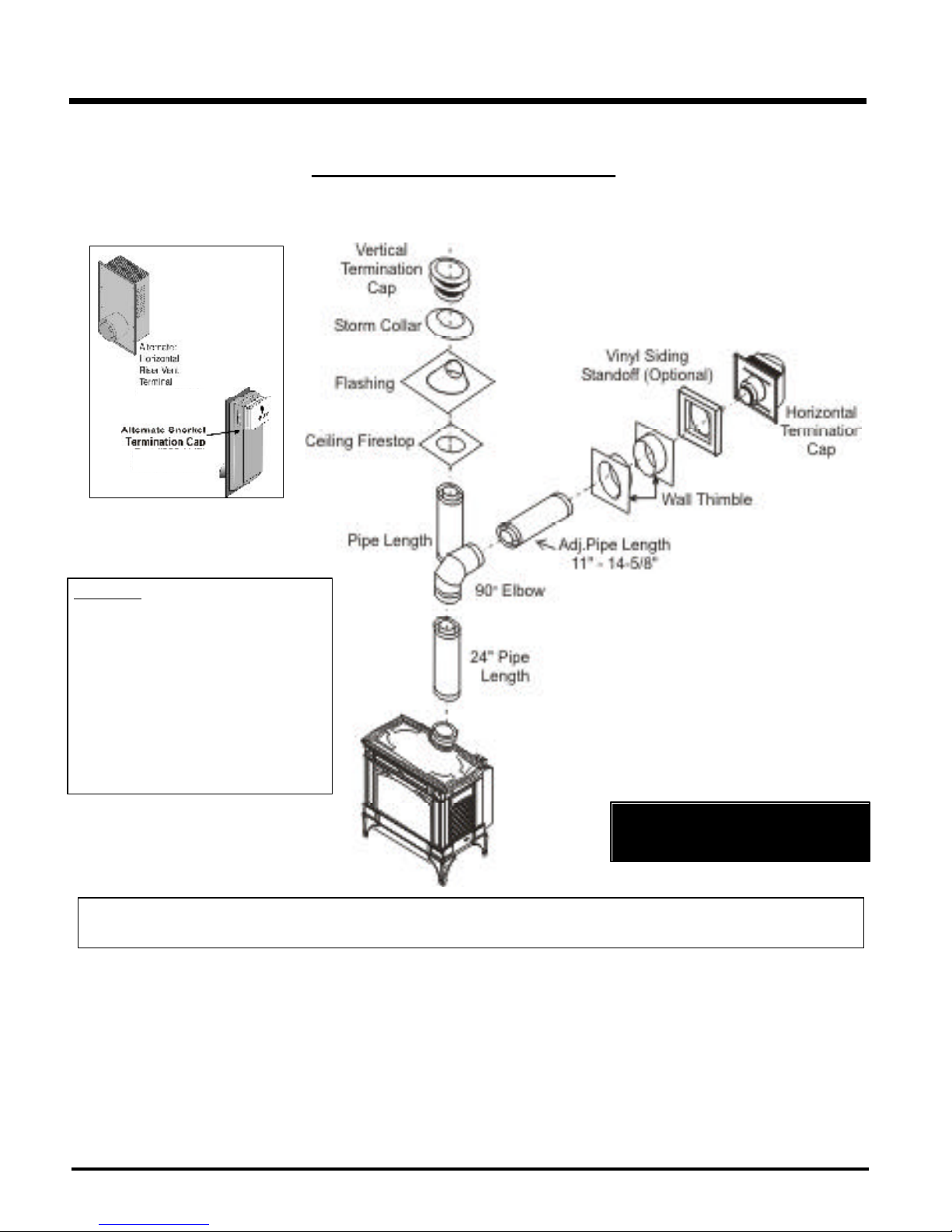
RIGID PIPE VENTING SYSTEMS
Horizontal or Vertical Terminations
WARNING:
Do not combine venting components from
different venting systems.
However use of the the AstroCapTM and FPI
Riser is acceptable with all systems.
This product has been evaluated by Intertek for
using a Dura-Vent Flue Adaptor in conjunction
with Selkirk Direct-Temp and Ameri Vent Direct
venting systems. Use of these systems with
the Direct Vent GS starting collar is deemed
acceptable and does not affect the Intertek WHI
listing of components.
When using piping other than
Simpson Dura-Vent, 3 screws must be
used to secure rigid pipe to adaptor.
The FPI AstroCap
GS, American Metal Products, Ameri Vent Direct vent and Selkirk Direct-Temp. FPITM, and FPI AstroCapTM are the proprietary trademarks of FPI
Fireplace Products International Ltd. Dura-Vent® and Direct Vent GS are registered and/or proprietary trademarks of Simpson Dura-Vent Co. Inc.
TM
and FPI Riser Vent terminal is certified for installations using FPI venting systems as well as Simpson Dura-Vent®, Direct Vent
12
Hampton H25 Direct Vent Freestanding Gas Stove
 Loading...