

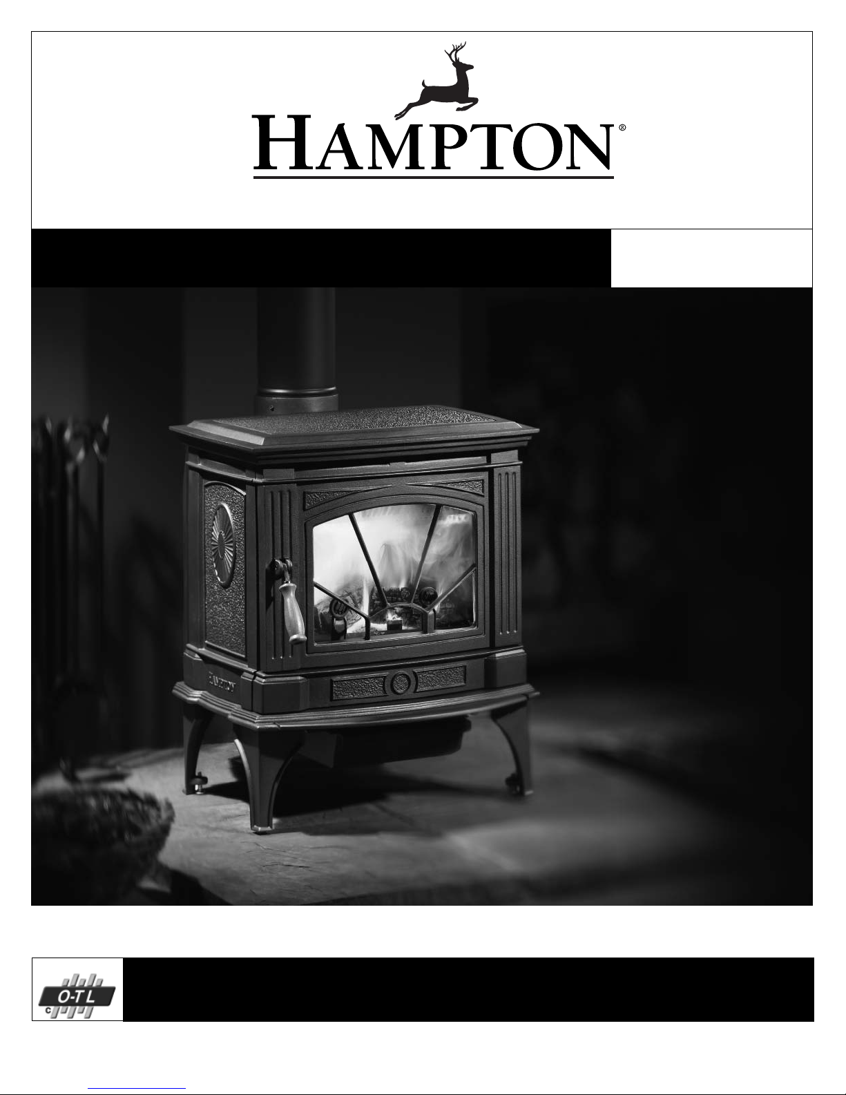
HAMPTON BAY H200 Owners & Installation Manual
www.hampton-fi re.com
Freestanding Woodstove
Owners &
Installation Manual
Tested by:
Homeowner: Please keep these instructions for future reference.
FPI FIREPLACE PRODUCTS INTERNATIONAL LTD. 6988 Venture St., Delta, BC Canada, V4G 1H4918-427
MODEL: H200
Installer: Please complete the details on the back cover
and leave this manual with the homeowner.
05/25/06

Thank-you for purchasing a
HAMPTON FIREPLACE PRODUCT.
The pride of workmanship that goes into each of our products will give you years of trouble-free enjoyment. Should you
have any questions about your product that are not covered in this manual, please contact the HAMPTON DEALER
in your area.
Keep those HAMPTON FIRES burning.
SAFETY NOTE: If this woodstove is not properly installed, a house fi re may result. For your safety, follow the installation instructions, contact local building, fi re offi cials, or authority having jurisdiction about restrictions and installation
inspection requirements in your area.
The authority having jurisdiction should be consulted before installation to determine the need to obtain a permit.
2
Hampton H200 Cast Freestanding Woodstove

TABLE OF CONTENTS
SAFETY LABEL
Safety Label for H200 ....................................................4
INSTALLATION
Unit Dimensions ............................................................5
Pre-installation Assembly ..............................................6
Residential Installation ..................................................7
Modular Installation Options ..........................................7
Minimum Clearance To Combustible Materials .............8
Minimum Alcove Clearance To Combustible Materials .. 9
Additional Clearances For Backwall Exit .......................9
Floor Protection ........................................................... 10
Step-by-step Chimney and Connector Installation ...... 11
Factory Built Chimney .................................................11
Masonry Chimney .......................................................12
Masonry Fireplace .......................................................12
Combustible Wall Chimney
Connector Pass-throughs ............................................13
Recommended Heights For Woodstove Flue ..............14
Mobile Home Installation ............................................. 15
Listed Components For Mobile Home Installation .......16
Brick Installation ..........................................................17
Door Removal .............................................................17
Optional Blower/Fan Installation ..................................18
Optional Side Shelf Installation ...................................19
OPERATING INSTRUCTIONS
Operating Instructions .................................................20
Fan Operation .............................................................20
First Fire ......................................................................20
Safety Guidelines And Warnings .................................21
Draft Control ................................................................ 21
Ash Drawer Kit Installation ..........................................22
Ash Disposal ...............................................................23
MAINTENANCE
Maintenance ................................................................24
Glass Installation/Replacement ...................................24
Creosote ......................................................................24
Wood Storage ..............................................................24
Glass Maintenance ......................................................24
Front Door Gasket .......................................................25
HandleReplacement ....................................................25
Latch Adjustment ......................................................... 25
Method ........................................................................25
PARTS LIST
Main Assembly ............................................................26
Door Assembly ............................................................28
Ash Drawer Assembly ................................................. 29
Fan Assembly .............................................................. 30
Hampton H200 Cast Freestanding Woodstove
WARRANTY
Warranty ......................................................................31
3
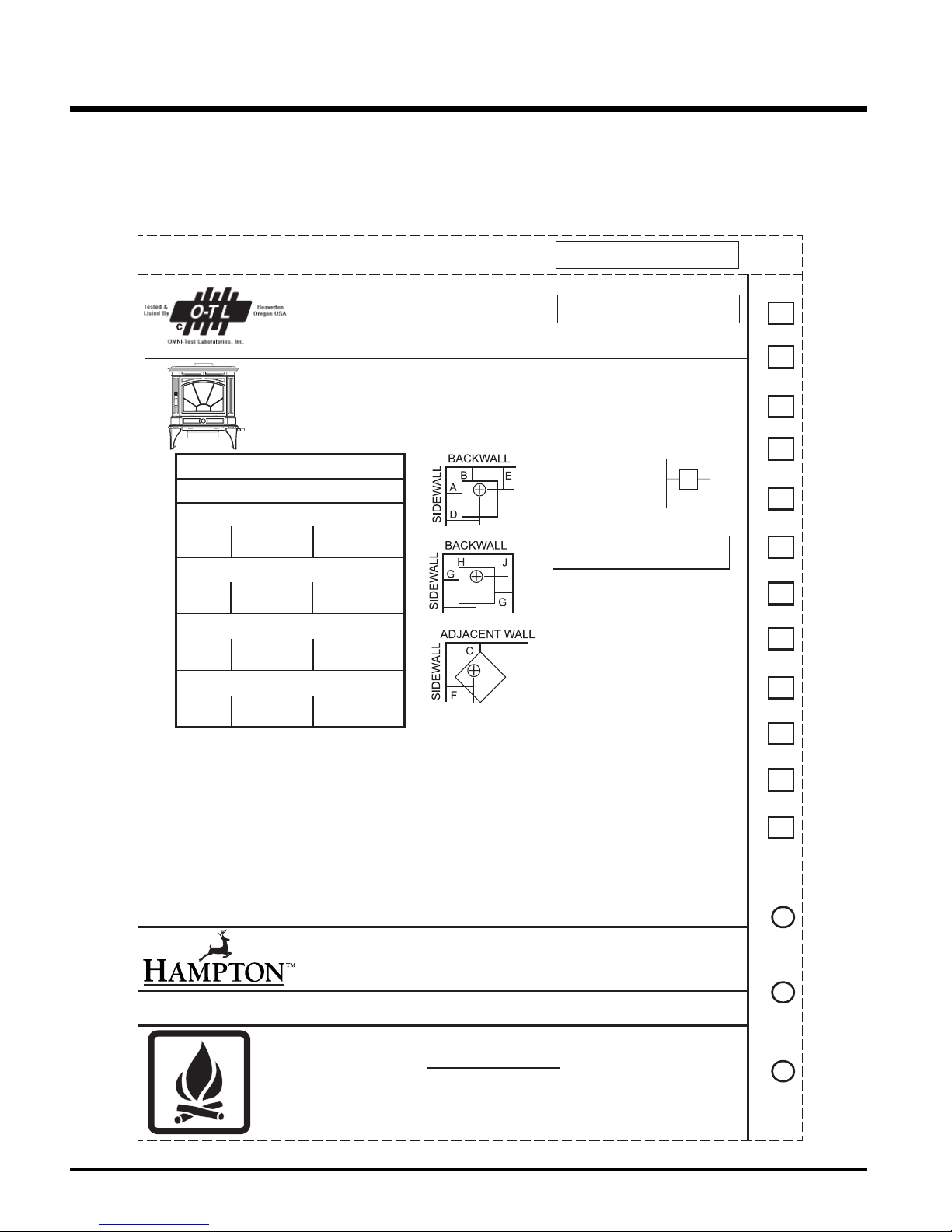
SAFETY LABEL
This is a copy of the label that accompanies
each Hampton H200 Freestanding Woodstove.
We have printed a copy of the contents here
for your review.
LISTED SPACE HEATER, SOLID FUEL TYPE, ALSO
SUITABLE FOR MOBILE HOME INSTALLATION
MODEL: HAMPTON CAST FREESTANDING WOOD STOVE - H200
TESTED TO: UL 1482 / ULC S627 REPORT NO: 219-S-09-2
INSTALL AND USE ONLY IN ACCORDANCE WITH THE MANUFACTURER'S INSTALLATION AND OPERATING INSTRUCTIONS.
CONTACT LOCAL BUILDING OR FIRE OFFICIALS ABOUT RESTRICTIONS AND INSTALLATION INSPECTION IN YOUR AREA.
USE 150 MM (6 IN.) DIAMETER MINIMUM 24 MSG BLACK OR 26 MSG BLUED STEEL CONNECTOR WITH LISTED UL103
HT FACTORY-BUILT CHIMNEY SUITABLE FOR USE WITH SOLID FUELS OR MASONRY CHIMNEY.
SEE LOCAL BUILDING CODE AND MANUFACTURER'S INSTRUCTIONS FOR PRECAUTIONS REQUIRED FOR PASSING A
CHIMNEY THROUGH A COMBUSTIBLE WALL OR CEILING. DO NOT PASS CHIMNEY CONNECTOR THROUGH COMBUSTIBLE
WALL OR CEILING. DO NOT CONNECT THIS UNIT TO A CHIMNEY FLUE SERVING ANOTHER APPLIANCE.
MINIMUM CLEARANCES TO
COMBUSTIBLE MATERIALS
MEASURE FLUE
FROM HEATER CENTER-LINE
RESIDENTIAL INSTALLATION USING
SIDEWALL A 431 mm / 17 in D 737 mm / 29 in
BACKWALL B 38 1 mm / 15 in E 435 mm / 17-1/8 in
CORNER C 3 30 mm / 13 in F 505 mm / 19-7/8 in
SIDEWALL A 381 mm / 15 in D 686 mm / 27 in
BACKWALL B 25 4 mm / 10 in E 308 mm / 12-1/8 in
CORNER C 2 28 mm / 9 i n F 403 mm / 15-7/8 in
SIDEWALL A 381 mm / 15 in D 686 mm / 27 in
BACKWALL B 25 4 mm / 10 in E 308 mm / 12-1/8 in
CORNER C 2 28 mm / 9 i n F 403 mm / 15-7/8 in
SIDEWALL G 381 mm / 15 in I 686 mm / 27 in
BACKWALL H 330 mm / 13 in J 384 mm / 15-1/8 in
MINIMUM ALCOVE CEILING HEIGHT: 1.5 M / 5 FT MAXIMUM ALCOVE DEPTH 1220 MM / 48 IN.
MINIMUM CLEARANCES FOR HORIZONTAL CONNECTOR TO CEILING: 457 MM / 18"
THE SPACE BENEATH THE HEATER MUST NOT BE OBSTRUCTED. OPERATE ONLY WITH FIREBRICKS IN PLACE.
FOR USE WITH SOLID WOOD FUEL ONLY. USE OF OTHER FUELS MAY DAMAGE HEATER AND CREATE A HAZARDOUS CONDITION. DO NOT OBSTRUCT
COMBUSTION AIR OPENINGS. OPERATE ONLY WITH FIREBRICKS IN PLACE. OPERATE ONLY WITH DOOR CLOSED - OPEN FEED DOOR TO FEED FIRE ONLY.
DO NOT USE GRATE OR ELEVATE FIRE. BUILD WOOD FIRE DIRECTLY ON HEARTH. DO NOT OVERFIRE - IF HEATER OR CHIMNEY CONNECTOR GLOWS YOU
ARE OVERFIRING. INSPECT AND CLEAN CHIMNEY AND CONNECTOR FREQUENTLY. UNDER CERTAIN CONDITIONS OF USE CREOSOTE BUILDUP MAY OCCUR
RAPIDLY. KEEP FURNISHINGS AND OTHER COMBUSTIBLE MATERIAL AWAY FROM HEATER. REPLACE GLASS ONLY WITH NEOCERAM GLASS.
COMBUSTIBLE FLOOR MUST BE PROTECTED BY NON-COMBUSTIBLE MATERIAL EXTENDING BENEATH THE HEATER AND TO THE FRONT AND SIDES AS
INDICATED OR TO THE NEAREST PERMITTED COMBUSTIBLE MATERIAL.
OPTIONAL COMPONENT: FAN (846-515), ELECTRICAL RATING: VOLTS 115, 60 HZ, 2 AMPS
DANGER: RISK OF ELECTRIC SHOCK. DISCONNECT POWER BEFORE SERVICING UNIT. DO NOT ROUTE POWER CORD UNDER OR IN FRONT OF APPLIANCE.
COMPONENTS REQUIRED FOR MOBILE HOME INSTALLATION: OUTSIDE AIR KIT AND ONE OF THE FOLLOWING DOUBLE WALL CONNECTOR
IN CANADA: LISTED SECURITY MODEL DP, OR OLIVER MACLEOD PRO-VENT PV DOUBLE WALLED CONNECTOR WITH LISTED CHIMNEY SYSTEM:
SECURITY MODEL S2100, ICC EXCEL 2100, SUPER VENT 2100, SUPERPRO 2100, CF SENTINAL.
IN USA: LISTED DOUBLE WALL CONNECTORS SECURITY MODEL DP, SELKIRK MODEL DS, OLIVER MACLEOD PRO VENT PV, SIMPSON DURA VENT MODEL
DVL, GSW SUPER PIPE 6, METAL-FAB DOUBLE WALL. CONNECTED TO ONE OF THE FOLLOWING COMPATIBLE CHIMNEY SYSTEMS SECURITY MODEL
S2100 OR MODEL ASHT, SELKIRK MODEL SSII, OLIVER MACLEOD PRO JET 3103, SIMPSON DURA PLUS, GSW MODEL SC OR METAL-FAB TEMP/GUARD,
AMERI-TECHS, ICC EXCEL 2100, SIMPSON DURA PLUS HTC . USE CHIMNEY COMPONENTS AS SPECIFIED IN INSTALLATION INSTRUCTIONS.
SINGLE WALL CONNECTOR
INSTALLATION USING LISTED DOUBLE WALL
CONNECTOR - MOBILE HOME
INSTALLATION USING LISTED DOUBLE WALL
CONNECTOR - RESIDENTIAL CLOSE CLEARANCE
INSTALLATION USING LISTED DOUBLE WALL
CONNECTOR - ALCOVE
UNITED STATES ENVIRONMENTAL
PROTECTION AGENCY
NOTE: Hampton units are constantly being
improved. Check the label on the unit and if
there is a difference, the label on the unit is the
correct one.
SAFETY LABEL FOR H200
290
DO NOT REMOVE THIS LABEL
290
PROTECTION*
K 457 mm / 18 in
L 150 mm / 6 in
M 150 mm / 6 in
* In Canada, floor protection must extend
18" (457mm) to the front and 8" (200mm)
to each side and back of the stove.
MANUFACTURED BY:
FPI FIREPLACE PRODUCTS INTERNATIONAL LTD.
6988 VENTURE ST.
DELTA, BC V4G 1H4
CERTIFIED TO COMPLY WITH JULY 1990
PARTICULATE EMISSION STANDARDS.
FLOOR
BACK
M
L
O
S
IDE
SIDE
FRONTK
MADE IN CANADA
DEC
NOV
OCT
SEPT
AUG
JUL
JUN
MAY
APR
MAR
FEB
JAN
2007
2006
HOT WHILE IN OPERATION DO NOT TOUCH. KEEP CHILDREN,
CLOTHING AND FURNITURE AWAY. CONTACT MAY CAUSE
SKIN BURNS. READ NAMEPLATE AND INSTRUCTIONS.
4
CAUTION
DATE OF MANUFACTURE
2005
918-428
Hampton H200 Cast Freestanding Woodstove
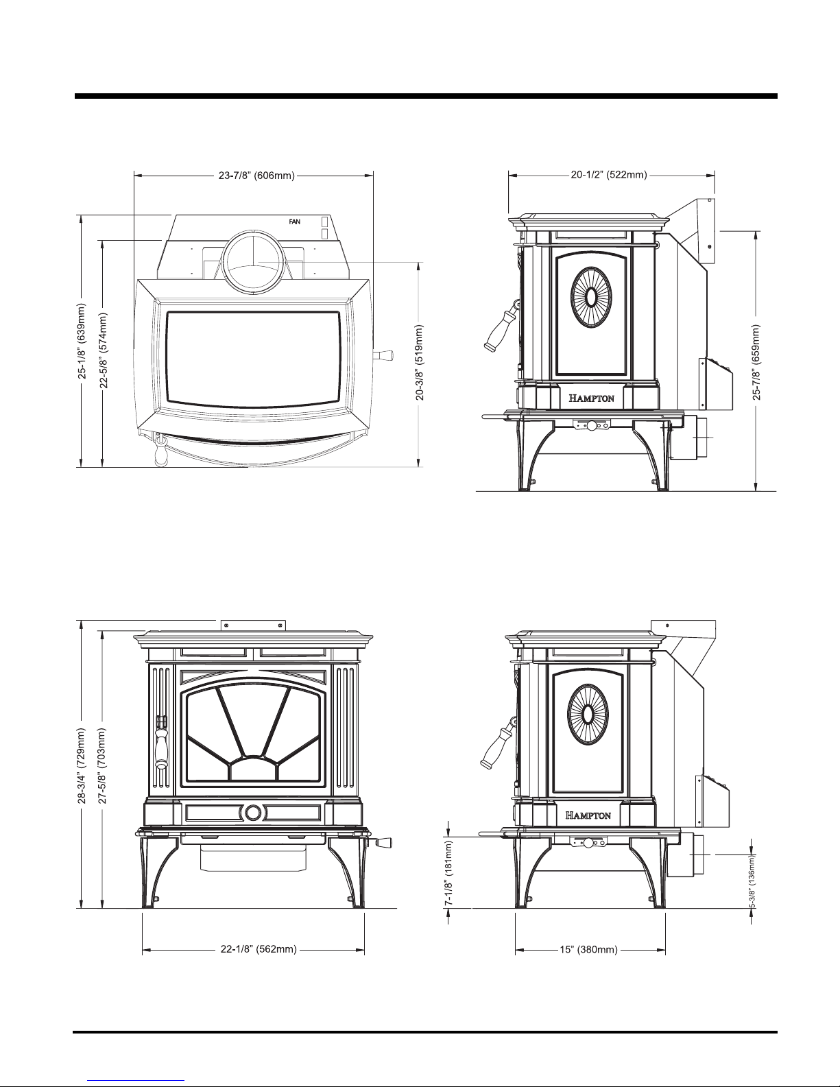
UNIT DIMENSIONS
INSTALLATION
Hampton H200 Cast Freestanding Woodstove
5
INSTALLATION
PRE-INSTALLATION
ASSEMBLY
After removing the stove from its packing, open
the front door and remove the contents from the
fi rebox, leaving the bricks in place.
Draft Control
Lever Handle
1) Insert bolt and lock washer through draft
control lever hole.
2) Place handle through bolt. Tighten to se-
cure.
Bolt Washer
Handle
Rotating Elbow
This stove can be connected to either a top or
rear vent exit by simply reversing the orientation
of the elbow.
Simply remove the 2 screws, change the position
of the elbow as desired and secure in place
with screws.
Rear Heat Shield
(Used only on Vertical Installations)
1) Loosen the bolts that secure the elbow to
the unit. Ensure elbow does not fall off.
3) Slide the tabs on the rear heat shield in
between the bolt and washer.
Please Note: The shield needs to be stretched/
fl exed in order to fi t in place.
Slide tabs in between
washer and bolt.
4) Once rear heat shield is evenly in place,
tighten bolts to secure.
Rear Heat Shield
Draft Control Lever
2) Bend the tabs on the rear heat shield inwards
90 degrees.
Bend tabs inwards 90 degrees.
6
Hampton H200 Cast Freestanding Woodstove
INSTALLATION
RESIDENTIAL
INSTALLATION
1) Please read this entire manual before you
install and use your new woodstove. Failure
to follow instructions may result in property
damage, bodily injury or even death. Be
aware that local Codes and Regulations
may override some items in this manual.
Check with your local inspector.
2) Select a position for your Hampton Stove.
Consult the minimum clearance chart for
your model and set the stove in place. For
close clearance installation use listed double
wall connector systems.
3) To insure vertical alignment, suspend a
plumb bob from the ceiling over the exact
center of your stove fl ue and mark a spot
on the ceiling to indicate the center of the
chimney.
4) Check that the area above the ceiling is
clear for cutting. Re-confi rm the clearance
from the stove to combustibles to insure that
they are within the prescribed limits.
5) This woodstove must be connected to a
UL 103 HT (ULC S629) listed chimney or
a code approved masonry chimney with a
fl ue liner, from the ceiling and beyond.
6) Install chimney according to chimney manu-
facturers instructions. The performance of
your woodstove is governed to a very large
part by the chimney system. Too short a
chimney can cause diffi cult start-up, dirty
glass, backsmoking when door is open, and
even reduced heat output. Too tall a chimney
may prompt excessive draft which can result
in very short burn times and excessive heat
output. The use of an inexpensive fl ue pipe
damper may be helpful in reducing excessive
draft.
CAUTION: The chimney should be the same
size as the 6" (152mm) fl ue outlet on the
stove. The chimney must be listed as suitable for use with solid fuels. For other types
of chimneys check with your local building
code offi cials. Do not confuse a chimney
with a type “B” Venting System used for gas
appliances as suitable for a wood burning
appliance (refer to the Mobile Home installations section).
7) Mark the location of the legs on the fl oor,
then move the stove aside and mark the
position of the fl oor protector.
8) The fl oor protector must be of non-combus-
tible material and must extend 18" (457mm)
in front of the door opening and 6" (152mm)
to the sides and rear of the unit. Some areas
may require a larger size fl oor protector.
See your local inspector. For outside air
installation (refer to Mobile Home installation
section).
NOTE: In Canada, fl oor protection must extend 18" (450mm) to the front and 8" (200mm)
to each side and back of the stove.
9) When the fl oor protection is complete, posi-
tion the stove with the fl ue collar centered
under the installed chimney.
10) In seismically active areas, we recommend
that your unit is secured to the fl oor by using
the bolt down holes inside the legs (the same
ones used in Mobile Home installations).
11) For residential installations using 6"
(152mm) "C" Vent (single wall) the chimney
connector must be at least 24 gauge steel.
Do not use galvanized pipe (refer to the
Mobile Home installation section).
12) Do not connect this unit to a chimney
serving another appliance.
13) A chimney connector cannot pass through
an attic or roof space, closet or similar
concealed space, or a fl oor, ceiling, wall
or partition of combustible construction.
In Canada, if passage through a wall, or
partition of combustible construction is
desired, the installation shall conform to
CAN/CSA-B365, Installation Code for SolidFuel-Burning Appliances and Equipment.
14) Your Hampton Woodstove is not to be connected to any air distribution duct.
Emissions from burning wood or gas could
contain chemicals known to the State of
California to cause cancer, birth defects
or other reproductive harm.
MODULAR INSTALLATION OPTIONS
OPTIONS: These can be installed at time of installation or added later:
Modular Option
Blower/Fan
Outside Air
Adaptor
Side Shelves
Ash Drawer
Hampton H200 Cast Freestanding Woodstove
Adding the blower will increase the area heated by the stove, it can move warm air beyond the room where the stove
is installed (refer to the Optional Blower / Fan Installation section).
Helps combustion in small or poorly ventilated houses. Installation instructions come with adaptor.
Add to the traditional look of the stove and double as a warming area for your cookstove creations.
Adding the ash drawer will allow for easier removal and transport of ashes.
Things to consider when choosing options
7
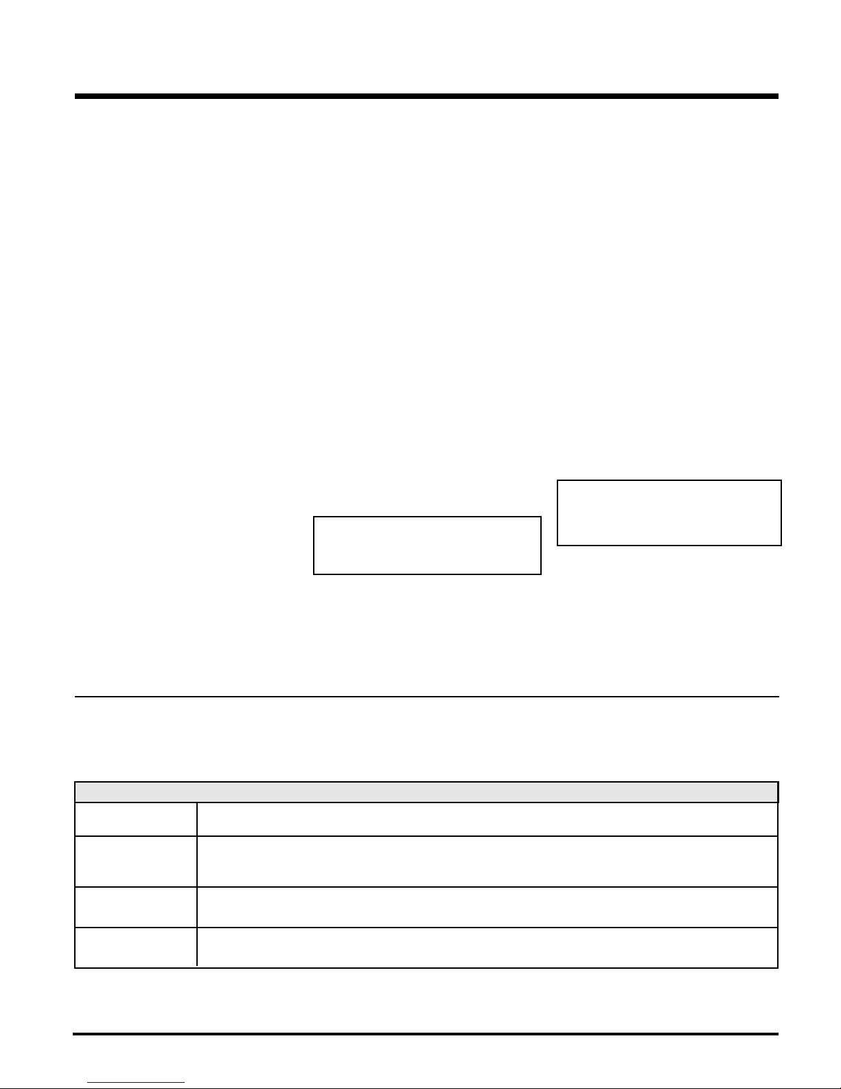
INSTALLATION
MINIMUM CLEARANCE TO
COMBUSTIBLE MATERIALS
Please read the section below carefully. Measurements "From Unit" are from the top plate of the stove to a side wall or to a corner, and from the
rear heat shield to a back wall.
Clearances may only be reduced by means approved by the regulatory authority.
Residential Installation “C” Vent (Single Wall)
Unit (with Heat Shield) From Unit From From Flue Center-Line
Corner
A B C D E F
H200 17" (431 mm) 15" (381 mm) 13" (330 mm) 29" (737 mm) 17-1/8"(435 mm) 19-7/8" (505mm)
Residential Close Clearance (To be installed with required pipe components)
When the stove is installed as a close clearance residential unit, a listed double wall connector is required from the stove collar to the ceiling
level.
Unit (with Heat Shield) From Unit From From Flue Center-Line
Corner
A B C D E F
H200 15" (381 mm) 10" (254 mm) 9" (228 mm) 27" (686 mm) 12-1/8" (308 mm) 15-7/8" (403mm)
Mobile Home Close Clearance (To be installed with required pipe components)
"C" Vent single wall pipe is not approved for Mobile Home installations (refer to Mobile Home Instructions).
Unit (with Heat Shield) From Unit From From Flue Center-Line
Corner
A B C D E F
H200 15" (381mm) 10" (254 mm) 9" (228mm) 27" (686mm) 12-1/8" (308mm) 15-7/8" (381mm)
8
Hampton H200 Cast Freestanding Woodstove
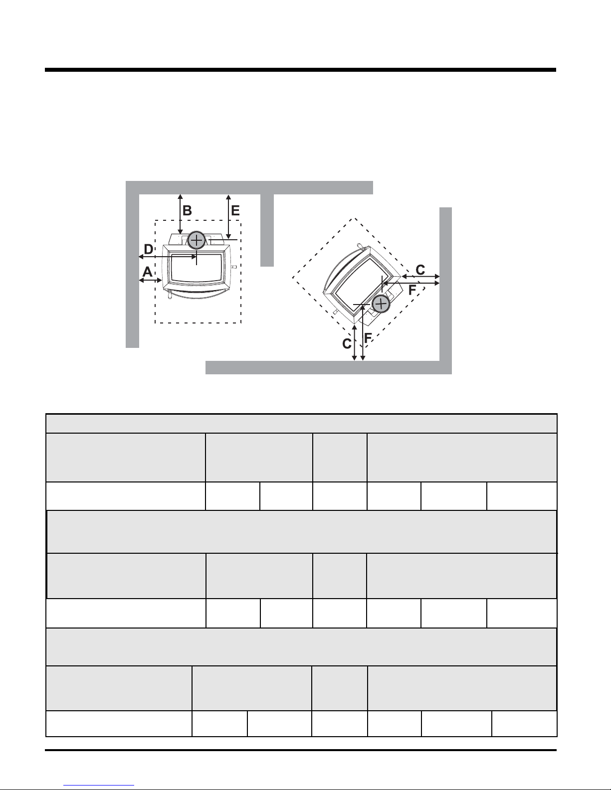
INSTALLATION
MINIMUM ALCOVE CLEARANCE TO
COMBUSTIBLE MATERIALS
This Hampton Freestanding model has been alcove approved and must be installed
with a listed double wall connector to the ceiling level.
Note: Minimum alcove ceiling height (from fi nished fl oor) - 60" (1525 mm)
Maximum depth of alcove - 48" (1220 mm)
From From Flue Min. Min.Hearth
Unit (with Heat Shield) Unit Center-line Width to Rear Wall
G H I J K L
H200 15" (381 mm) 13" (330 mm) 27" (686 mm) 15-1/8" (384 mm) 54" (1372 mm) 50" (1270 mm)
ADDITIONAL CLEARANCES
FOR BACKWALL EXIT
Minimum Clearance to Combustibles
From
Unit (with Heat Shield) Unit
A B
H200 9" (228 mm) 15" (381 mm)
Minimum Clearance to Non-Combustibles
From
Unit (with Heat Shield) Unit
A B
H200 min. 0" (0 mm) 15" (381 mm)
max. 9" (228 mm)
Min. Mantel Height (from fi nished fl oor): 48" (1219 mm)
Max. Mantel Depth: 12" (305 mm)
Hampton H200 Cast Freestanding Woodstove
Note: Floor Protection must extend 2" (50mm)
to each side of the elbow.
9
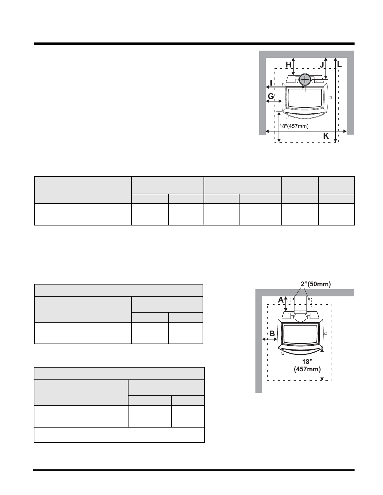
INSTALLATION
FLOOR PROTECTION
A combustible fl oor must be protected by non-combustible material (like tile, concrete board, or certifi ed to UL-1618 or as defi ned by local codes)
extending beneath the heater and a minimum of 6" from each side and minimum 18" from the front face of the stove and minimum 6" (or the rear
clearance to combustibles whichever is smaller) from the rear of the stove.
When installed with horizontal venting, non-combustible fl oor protection must beneath the fl ue pipe and extend 2" (51mm) beyond each side.
NOTE: In Canada, fl oor protection must
extend 18" (450mm) to the front
and 8" (200mm) to each side and
back of the stove.
Minimum Overall Depth (Y) of Floor Protector
Residential Residential Mobile Home Alcove
Unit "C" Vent Close Clearance Close Clearance
Y Z Y Z Y Z Y Z
H200 (US) 43" 6" (152 mm) 43" 6" (152 mm) 43" 6" (152 mm) 43" 6" (152 mm)
(1092 mm) (1092 mm) (1092 mm) (1092 mm)
H200 (Canada) 45" 8" (203 mm) 45" 8" (203 mm) 45" 8" (203 mm) 45" 8" (203 mm)
(1143 mm) (1143 mm) (1143 mm) (1143 mm)
Minimum Overall Width (X) of Floor Protector for all installations:
H200 36" (914 mm) - US
40" (1016 mm) - Canada
10
Hampton H200 Cast Freestanding Woodstove
 Loading...