

HAMPTON BAY EST-540T-10-Y, EST-534T-10-Y Use And Care Manual

C US
Item #205107905
Model #EST-540T-10-Y
USE AND CARE GUIDE
LEGACY PANORAMIC INFRARED STOVE
IMPORTANT INSTRUCTIONS
PLEASE READ THIS MANUAL BEFORE INSTALLING AND USING APPLIANCE
IF THE INFORMATION IN THIS MANUAL IS NOT FOLLOWED EXACTLY,
CAUSING PROPERTY DAMAGE, PERSONAL INJURY OR LOSS OF LIFE.
CONSUMER:
Questions, problems, missing parts? Before returning to the store,
We appreciate the trust and confidence you have placed in Hampton Bay through the purchase of this electric log insert. We strive to
continually create quality products designed to enhance your home. Visit us online to see our full line of products available for your home
20-10-202
improvement needs. Thank you for choosing Hampton Bay!
Patent
pending
WARNING!
AN ELECTRICAL SHOCK OR FIRE MAY RESULT
INSTALLER:
Leave this manual with the appliance.
Retain this manual for future reference.
call Hampton Bay Customer Service
8 a.m. - 6 p.m., EST, Monday - Friday
855-HD-HAMPTON HAMPTONBAY.COM
THANK YOU
1
REV. 4/2014
Table of Contents
Table of Contents .................................................................... 2
Safety Information .................................................................. 3
Warranty .................................................................................. 5
Pre-Installation ....................................................................... 6
Stove Dimensions ................................................................ 6
Tools Required ..................................................................... 7
Package Contents ................................................................ 7
IMPORTANT: Read all instructions and warnings carefully before starting installation.
Failure to follow these instructions may result in a possible electric shock, injury to persons, fire hazard and will void the warranty.
Please read the Installation & Operating Instructions before using this appliance.
Installation ............................................................................... 8
Operation ................................................................................. 9
Care and Maintenance ...........................................................10
Electric Wiring Diagram .........................................................11
Troubleshooting .....................................................................12
Replacement Parts ................................................................13
CAUTION
PRODUCT DAMAGE MAY OCCUR.
Never attempt to disassemble or alter the product in any way not instructed by this manual.
2
Safety Information
Please read and understand this entire manual before attempting to assemble, operate or install the product.
□ Read all instructions before using this appliance.
□ This appliance is hot when in use. To avoid burns, do not let bare skin touch hot surfaces. If provided, use handles when moving this
appliance. Keep combustible materials, such as furniture, pillows, bedding, papers, clothes and curtains at least 3 ft. (914 mm) from
the front of this appliance and keep them away from the sides and rear.
CAUTION: Extreme caution is necessary when any heater
is used by or near children or invalids and whenever the
heater is left operating unattended.
□ If possible, always unplug this appliance when not in use.
□ Do not operate any heater with a damaged cord or plug or after the appliance malfunctions, has been dropped or damaged in any
manner.
□ Any repairs to this appliance should be carried out by a qualified service person.
□ Under no circumstances should this appliance be modified. Parts having to be removed for servicing must be replaced prior to
operating this appliance again.
□ Do not use outdoors.
□ This heater is not intended for use in bathrooms, laundry areas and similar indoor locations. Never place this appliance where it
may fall into a bathtub or other water container.
□ Do not use this heater in elevated locations, such as on shelves, raised platforms, etc.
□ Do not run the cord under carpeting. Do not cover the cord with throw rugs, runners or the like. Arrange the cord away from traffic
areas and where it will not be tripped over.
□ To disconnect this appliance, turn the controls to the off position, then remove the plug from the outlet.
□ Connect to properly grounded outlets only.
□ This appliance, when installed, must be electrically grounded in accordance with local codes, with the current CSA C22.1 Canadian
Electrical codes or for USA installations, follow local codes and the National Electric Code, ANSI/NFPA No. 70.
□ Do not insert or allow foreign objects to enter any ventilation or exhaust opening, as this may cause an electric shock, fire, or
damage to the appliance.
□ To prevent possible fire, do not block air intakes or exhaust in any manner. Do not use on soft surfaces, like a bed, where
openings may become blocked.
□ This appliance has hot and arcing or sparking parts inside. Do not use it in areas where gasoline, paint, or flammable liquids are
used or stored. This appliance should not be used as a drying rack for clothing, nor should Christmas stockings or decorations be
hung on or near it.
□ Use this appliance only as described in this manual. Any other use not recommended by the manufacturer may cause fire, electric
shock, or injury to persons.
□ Always plug heaters directly into a wall outlet/receptacle. Always plug the unit into a wall outlet/receptacle. An extension cord or
re-locatable power tap, (outlet/power strip), should never be used.
□ Do not use this heater with missing, damaged, or broken legs.
□ “SAVE THESE INSTRUCTIONS FOR FUTURE USE”
Please contact 855-HD-HAMPTON for further assistance.
3
HAMPTONBAY.COM
Safety Information (continued)
DANGER
ELECTRICAL CONNECTION
A 15-Amp, 120-Volt, 60 Hz circuit with a properly grounded outlet is required. Preferably, the item will be on a dedicated circuit as other appliances on the same circuit may cause the circuit breaker to trip or the fuse to blow when
the heater is in operation. The unit comes standard with a 6 ft. (1.8 m) long three wire cord, exiting the right side of
the item. Always plug the unit into a wall outlet/receptacle. An extension cord or re-locatable power tap, (outlet/power
strip), should never be used.
Electrical outlet wiring must comply with local building codes and other
applicable regulations to reduce the risk of fire, electrical shock and injury
to persons.
Do not use this item if any part of it has been under water. Immediately
call a qualified service technician to inspect the item and replace any part
of the electrical system which has been under water.
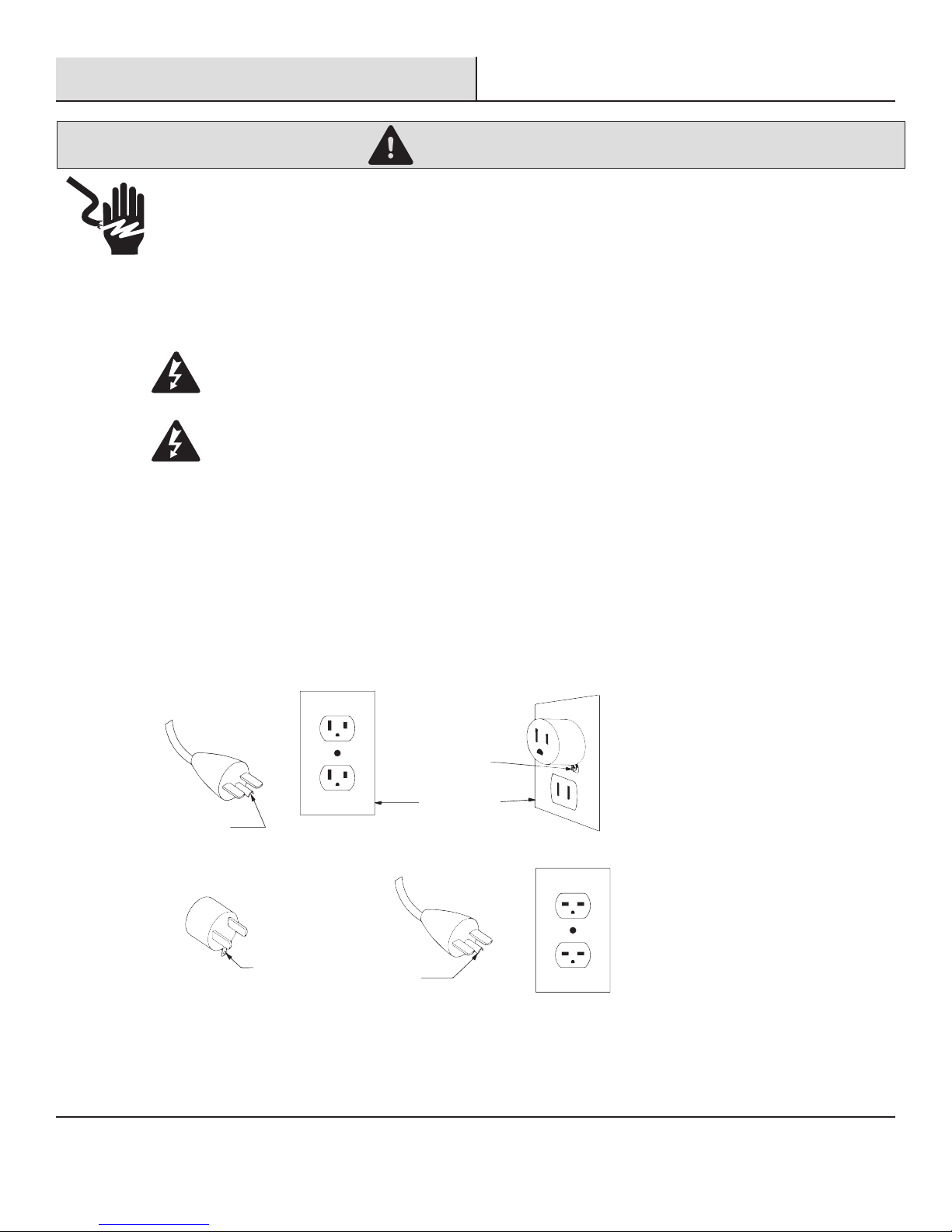
GROUNDING INSTRUCTIONS
This heater is for use on 120 volts. The cord has a plug as shown at (A) in Figure 1. An adapter as shown at (C) is available for connecting three-blade grounding-type plugs to two-slot receptacles. The green grounding lug extending from the
adapter must be connected to a permanent ground such as a properly grounded outlet box. The adapter should not be used
if a three-slot grounded receptacle is available.
Figure 1
GROUNDING
PIN
(C)
(A)
ADAPTER
GROUNDING
MEANS
METAL SCREW
COVER OF GROUNDED
OUTLET BOX
GROUNDING
PIN
(B)
(D)
NOTE: Adapters are NOT
for use in Canada.
4

Warranty
1-YEAR WARRANTY
WHAT IS COVERED
The manufacturer warrants that your new electric stove is free from manufacturing and material defects for a period of one year from date of
purchase, subject to the following conditions and limitations.
This electric stove must be installed and operated at all times in accordance with the instructions furnished with the product. Any alteration,
willful abuse, accident, or misuse of the product shall nullify this warranty. This warranty is non-transferrable, and is made to the original
owner, provided that the purchase was made through an authorized supplier of the manufacturer. This warranty is limited to the repair or
replacement of part(s) found to be defective in material or workmanship, provided that such part(s) have been subjected to normal conditions
of use and service, after said defect is confirmed by the manufacturer’s inspection. The manufacturer may, at its discretion, fully discharge
all obligations with respect to this warranty by refunding the wholesale price of the defective part(s).
WHAT IS NOT COVERED
Any installation, labor, construction, transportation, or other related costs/expenses arising from defective part(s), repair, replacement, or
otherwise of same, will not be covered by this warranty, nor shall the manufacturer assume responsibility for same. Further, the manufacturer
will not be responsible for any incidental, indirect, or consequential damages, except as provided by law.
All other warranties - expressed or implied - with respect to the product, its components and accessories, or any obligations/liabilities on the
part of the manufacturer are hereby expressly excluded. The manufacturer neither assumes, nor authorizes any third party to assume, on its
behalf, any other liabilities with respect to the sale of this product. The warranties as outlined within this document do not apply to nonmanufacturer accessories used in conjunction with the installation of this product.
This warranty does not cover the lightbulb(s) included with the fireplace.
This warranty is void if: the fireplace has been operated in atmospheres contaminated by chlorine, fluorine, or other damaging chemicals; the
fireplace is subjected to prolonged periods of dampness or condensation; the fireplace is altered, willfully abused, damaged by accident, or
misused in any way.
If warranty service is needed, contact the Customer Service Team at 855-HD-HAMPTON from 8 a.m. - 6 p.m., EST, Monday-Friday or visit
www.hamptonbay.com.
Make sure you have your warranty, your sales receipt, and the model/serial number of your product.
DO NOT ATTEMPT TO DO ANY SERVICE WORK YOURSELF.
5
Please contact 855-HD-HAMPTON for further assistance.
HAMPTONBAY.COM
Pre-Installation
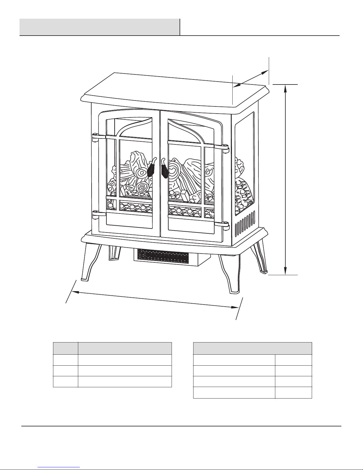
STOVE DIMENSIONS
A
B
Ref. EST-540-10-Y
A 15 in. (38.1 cm)
B 28.5 in. (72.39 cm)
C 25 in. (63.5 cm)
C
Technical Specifications
Voltage
Frequency
Amps
Rating
6
120V AC
60HZ
12.5A
1500W
Pre-Installation (continued)
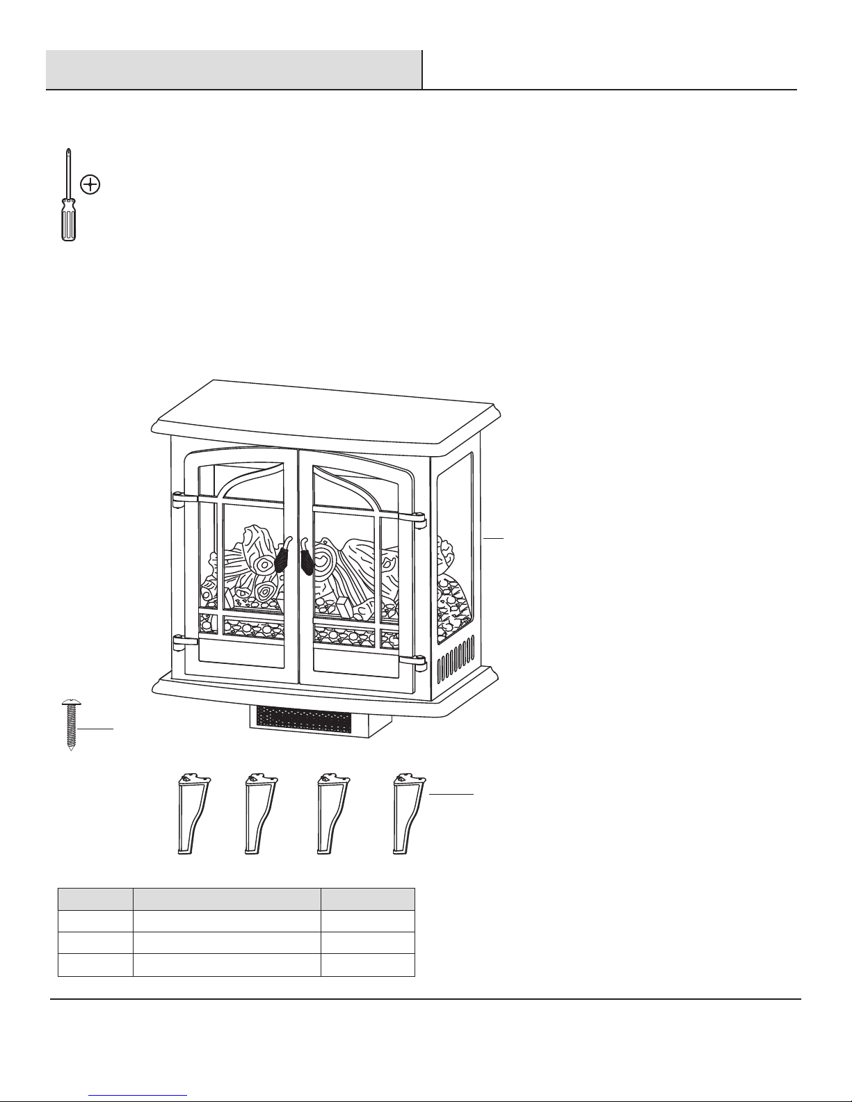
TOOLS REQUIRED
Phillips
screwdriver
(not included)
PACKAGE CONTENTS
Open the unit and check carefully for visible damage. If you have any problems with installation,
operation, missing parts, or damage, please contact the Customer Service Team at 855-HD-HAMPTON.
DO NOT dispose of packaging until you are satisfied with your stove.
DO NOT return the unit to the store before calling 855-HD-HAMPTON for service.
C
Part Description Quantity
A Electric Stove 1
B Leg 4
C Screw 8
A
B
Please contact 855-HD-HAMPTON for further assistance.
7
HAMPTONBAY.COM
Installation
The stove should be located in an area:
□ Out of direct sunlight
□ Not susceptible to moisture
□ Away from uninsulated outside wall
WARNING
□
The stove is heavy and should be assembled near its
desired location.
□
It is recommended that two people move the assembled
stove to prevent injury.
WARNING
Do not install the unit on shelves, raised platforms, beds, blankets, pillows etc. Keep combustible materials such as furniture, bedding,
papers, clothes and curtains at least 3 ft. (914 mm) from the stove.
Clearance to Combustibles
Sides 4 in. (101.6 mm)
Floor 0 in. (0 mm)
Top 36 in. (914 mm)
Front 36 in. (914 mm)
Rear 0 in. (0 mm)
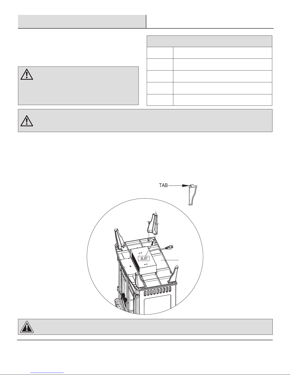
ASSEMBLY INSTRUCTIONS
1. Lay the stove (A) upside down on a padded surface with the underside accessible. Attach the leg (B) to the stove by inserting the tab on
the top of each leg (B) into the corresponding slot on the bottom of the stove (A). Insert two screws (C) into predrilled holes and tighten
securely for each leg (B).
2. Carefully position the stove against a wall.
3. Plug the power cord into the 15-amp, 120-volt outlet. Use an extension cord rated for a minimum of 1,875 watts if necessary.
B
B
C
C
A
CAUTION
Make sure that the unit is installed so that the power cord is not compressed against or caught on the stove and that it has an unobstructed path to the grounded outlet.
8
Operation
Read All Instructions Before Use
Check that the heater outlet grill is not covered or obstructed in anyway, and make sure the power to the unit is switched on.
NOTE:
When the heat function is used for the first time, a slight odor may be present. This is normal and should not occur again unless the
heater is not used for an extended period of time.
1
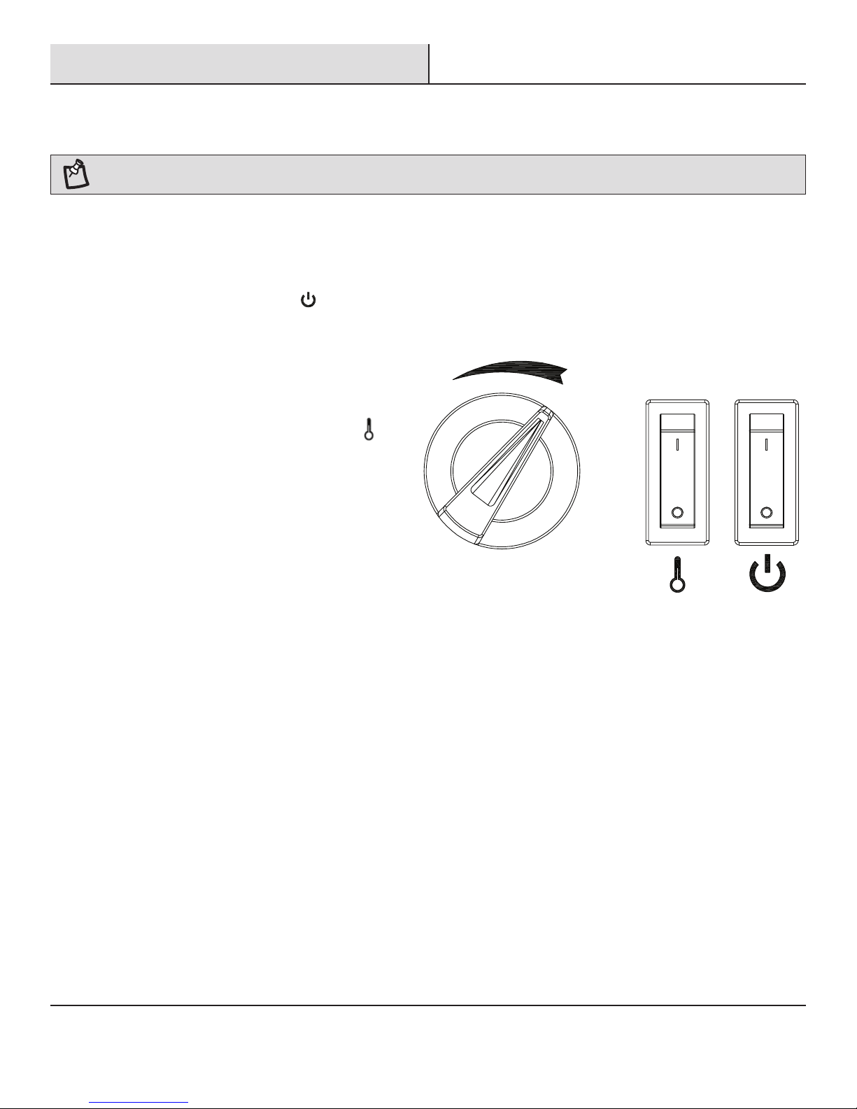
Using the Control Panel
□ The control panel is located behind the door of the stove.
□ Main Power Switch: The Power Switch
supplies power to all of the functions of the
stove. This switch must be in the ON position for
any functions to work.
□ Flame Effect: Toggle the Power Switch ON. The
Power indicator light will glow. The flame effect
will be visible through the front glass.
□ Temperature Knob: Toggle the Temperature
Switch ON, the Temperature control knob
regulates the temperature level of the room.
The further the knob is rotated clockwise, the
higher the temperature setting. Turning the knob
counter-clockwise will lower the temperature
setting. Use this function to help regulate the
ambient temperature level.
□ Temperature Limiting Control: This heater is
equipped with a Temperature Limiting Control.
Should the heater reach an unsafe temperature,
the heater will automatically turn off. To reset:
Unplug the power cord from the outlet. Wait
5 minutes. With the Power switch in the OFF
position, plug the power cord back into the
outlet.
Please contact 855-HD-HAMPTON for further assistance.
9
HAMPTONBAY.COM
Maintenance
GLASS INFORMATION
□ Under no circumstances should this product be operated with broken glass.
□ Do not strike or slam the glass.
□ Do not use abrasive cleaners to clean the glass.
□ This product uses tempered glass. Replacement of the glass supplied by the manufacturer should be done by a qualified service person.
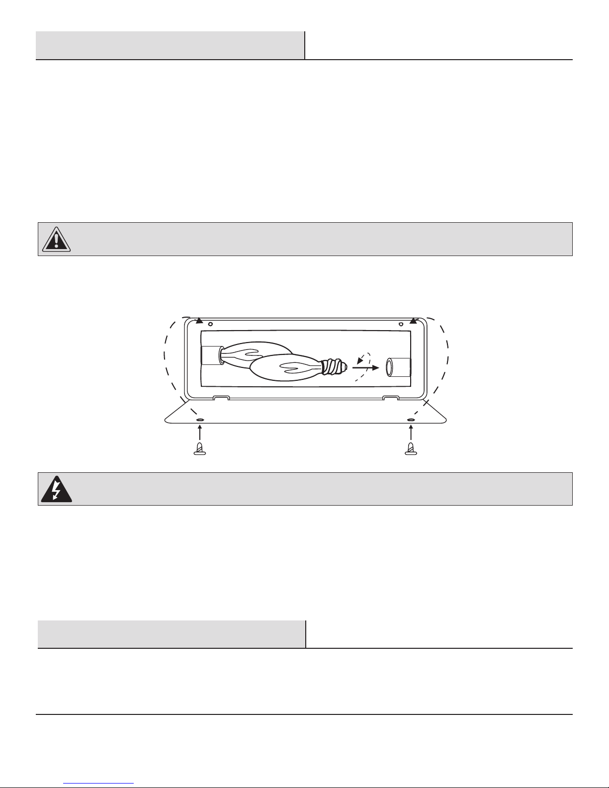
LIGHT BULB INSPECTION AND REPLACEMENT
The flame effect is created by two 40-Watt light bulbs with an E-12 (small) socket base. Use only this type of light bulb. If the flame effect
does not work, the bulbs may have come loose or been damaged during shipping.
CAUTION
Light bulbs become very hot during use. Allow at least 10 minutes for the bulbs to cool before touching.
To inspect or replace the bulbs, first unplug the power cord from the outlet. Locate the access panel on the back of the stove. Remove the
screws and the panel. Check the bulbs to be sure they are finger tight and in working order. Replace any damaged or faulty bulbs. Reattach
the access panel. Do not operate this heater without the access panel in place. Do not remove the back cover of this heater. There are no
serviceable parts inside.
WARNING
Do not exceed 40 watts per bulb. Use of higher rated bulbs may result in a fire, causing property damage or personal injury.
MOTOR MAINTENANCE
Always disconnect the appliance from the main power supply and allow it to cool before any servicing operation.
The motors used on the fan heater and flame blower are pre-lubricated for extended bearing life and require no further lubrication. However, periodic cleaning/vacuuming of the appliance around the air intake and exhaust, as well as the fan heater is recommended. For heavy or continuous
use, periodic cleaning must be done more frequently. If the heater blows alternating cold and warm air, check the fan for free movement and for
debris restricting air flow. If the fan does not move freely, the unit must be turned off and the fan replaced immediately in order to prevent further
damage to the unit.
Care & Cleaning
Always turn the stove OFF and unplug the power cord from the outlet before cleaning. Use a vacuum or duster to remove dust and dirt
from the heater and vent areas. To maintain the finish, clean with a soft, slightly damp cloth and buff with a dry cloth. Never use abrasive
cleansers, liquid sprays, or any cleaner that could scratch the surface.
10

Electric Wiring Diagram
Disconnect power before servicing.
Any electrical re-wiring of this appliance must be done by a qualified electrician. This wiring must be done in
accordance with local codes and/or in Canada with the current CSA C22.1 Canadian Electrical Code, and for US
installations, the National Electrical Code ANSI/NFPA NO 70.
If repairing or replacing any electrical component or wiring, the original wire routing, color coding and securing
locations must be followed.
CIRCUIT DIAGRAM
DANGER
AC120V /
60HZ
S1
BULB 1
L
BULB 2
40W
N
GND
FLAME EFFECT
MOTOR
WARNING: Disconnect power before servicing.
40W
TEMPERATURE
CONTROL
S2
THERMAL
CUTOFF
HEATER
ELEMENT
THERMAL
FUSE
FAN
MOTOR
Please contact 855-HD-HAMPTON for further assistance.
11
HAMPTONBAY.COM

Troubleshooting
If you have any questions regarding the product, please call Hampton Bay Customer Service, 855-HD-HAMPTON, 8 a.m. – 6 p.m. EST,
Monday – Friday.
Problem Possible Cause Corrective Action
The stove does
not operate.
The power light is ON but
the flame effect is not
visible.
The heater is not
operating.
□ The stove is not plugged in.
□ A circuit breaker is tripped or a fuse
blown.
□ The ON/OFF switch is defective.
□ There is loose wiring.
□ The stove is not operating correctly.
□ There are loose light bulb(s).
□ There are burnt out light bulb(s).
□ The stove is not operating correctly.
□ The heater switch is defective.
□ The heater assembly is defective.
□ There is loose wiring.
□ The vents are dirty or clogged.
□ Make sure the fireplace is plugged in
to a standard 120V outlet.
□ Check additional appliances on the
circuit; ideally the fireplace should be
on a dedicated 15-amp circuit.
□ Call customer service.
□ Call customer service.
□ Refer to the operating instructions.
□ Tighten the light bulb(s).
□ Replace the light bulb(s).
□ Refer to the operating instructions.
□ Call customer service.
□ Call customer service.
□ Call customer service.
□ Unplug the unit. Clear the vent area of
dust and debris. Wait ten minutes, plug
the unit in again and turn on the heater.
There is excessivee
noise when the heater is
operating.
□ The fan is defective.
□ The heater assembly is defective.
□ Call customer service.
□ Call customer service.
12
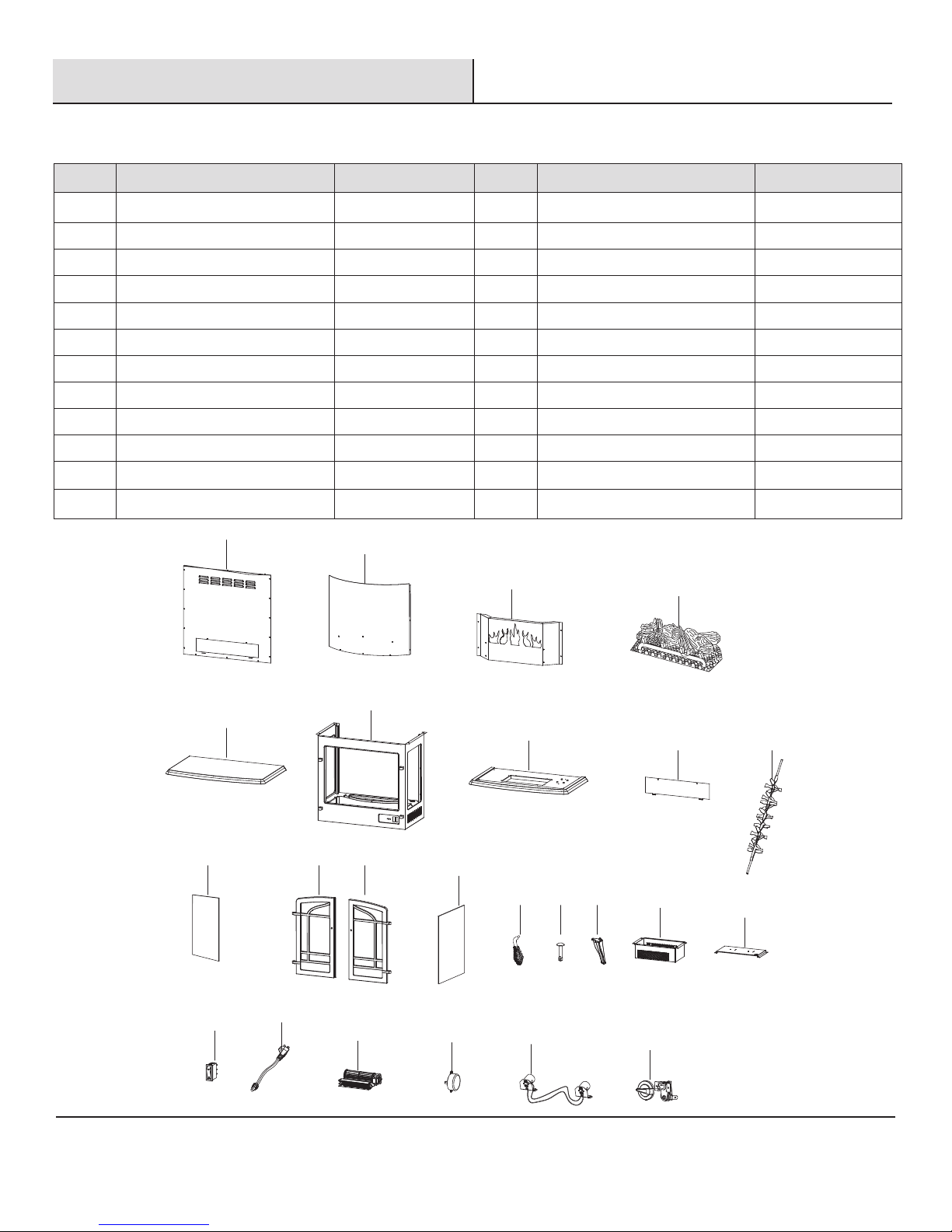
Replacement Parts
1
5
10
19
21
22
23
24
20
11 12
13
14 15 16
17
18
6
7
8 9
2
3
4
If you have any questions regarding the product, please call Hampton Bay Customer Service, 855-HD-HAMPTON, 8 a.m. – 6 p.m. EST,
Monday – Friday.
Ref. Description Part No.
1 Back Panel
2 Screen
3 Flame Panel
4 Log Set
5 Top Panel
6 Cabinet Panel
7 Bottom Panel
8 Access Panel
9 Flame Reflector
10 Glass
11 Left Door
12 Right Door
EFEST330001ST
EFEST330002ST
EFEST330003ST
EFEST330004ST
EFEST330005ST
EFEST340001ST
EFEST330007ST
EFEST330008ST
EFEST330009ST
EFSES81001ST
EFEST330012ST
EFEST330013ST
Ref. Description Part No.
13 Side Glass
14 Handle
15 Hinge Pin
16 Leg (Design 1)
17 Fan Heater Box
18 Light Barrier Panel
19 Switch
20 Power Cord & Connector
21 Heater (IR)
22 Motor
23 Lamp Socket & Bracket
24 Thermostat
EFSES81003ST
EFES323012ST-14
EFES323013ST
EFEST330015ST
EFES323015ST
EFEST330016ST
EFES323017ST
EFES323018ST
EFES322007ST-14
EFES323020ST
EFES323021ST
EFES322006ST
Some parts and specifications may change without notice.
Please contact 855-HD-HAMPTON for further assistance.
13
HAMPTONBAY.COM
 Loading...