

HAMPTON BAY Antigua Plus, 56” Antigua Plus User Manual


56” Antigua Plus
Ceiling Fan by Hampton Bay
Accu-Arm™ for Accurate
and Easy Installation
Steeper Blade Pitch for
Greater Air Movement
3-Speed Reverse Function for
Year-Round Comfort and Savings
Tri-Mount Installation
QUESTIONS, PROBLEMS, MISSING PARTS:
Before returning to your local Home Depot, please call our
Customer Service Team at 1-877-527-0313 or visit www.homedepot.com.
Please reference your SKU (926 906 oil-rubbed bronze)
or UPC (082392 73540 1R oil-rubbed bronze).
Thank you for purchasing this Hampton Bay ceiling
fan. This product has been manufactured with the
highest standards of safety and quality. The nish
of this fan is weather resistant, but over time will
naturally weather and fade.
Safety Rules .................................. 1
Unpacking Your Fan .................... 2
Installing Your Fan ...................... 3
Operating Your Fan ..................... 10
Care of Your Fan .......................... 11
Troubleshooting ............................ 11
Specications ................................ 12
Warranty Information ................. 13
Table of Contents
UL Model No. 56-ANTHL
1. To reduce the risk of electric shock, insure electricity
has been turned off at the circuit breaker or fuse box
before beginning.
2. All wiring must be in accordance with the National
Electrical Code ANSI/NFPA 70-1999 and local electrical
codes. Electrical installation should be performed by a
qualied licensed electrician.
3. WARNING: To reduce the risk of re or electric shock, do
not use this fan with any solid-state speed control device.
4. CAUTION: To reduce the risk of personal injury, use only
the screws provided with the outlet box.
5. The outlet box and support structure must be securely
mounted and capable of reliably supporting a minimum of
35 pounds. Use only UL Listed outlet boxes marked “FOR
FAN SUPPORT.”
6. The fan must be mounted with a minimum of 7 feet
clearance from the trailing edge of the blades to the oor.
7. Do not operate reversing switch while fan blades are in mo-
tion. Fan must be turned off and blades stopped before reversing blade direction.
8. Avoid placing objects in path of the blades.
9. To avoid personal injury or damage to the fan and other items,
be cautious when working around or cleaning the fan.
10. Do not use water or detergents when cleaning the fan or fan
blades. A dry dust cloth or lightly dampened cloth will be
suitable for most cleaning.
11. After making electrical connections, spliced conductors
should be turned upward and pushed carefully up into
outlet box. The wires should be spread apart with the
grounded conductor and the equipment-grounding
conductor on one side of the outlet box.
12. Electrical diagrams are for reference only. Light kits that are
not packed with the fan must be UL listed and marked suitable
for use with the model fan you are installing. Switches must be
UL General Use Switches. Refer to the instructions packaged
with the light kits and switches for proper assembly.
Safety Rules 1.
READ AND SAVE THESE INSTRUCTIONS
TO REDUCE THE RISK OF FIRE, ELECTRIC SHOCK OR PERSONAL
INJURY, MOUNT TO OUTLET BOX MARKED ACCEPTABLE FOR FAN
SUPPORT AND USE SCREWS PROVIDED WITH THE OUTLET BOX.
PLEASE REMOVE RUBBER MOTOR STOPS ON THE BOTTOM OF THE
FAN BEFORE INSTALLING BLADES OR TESTING THE MOTOR.
TO REDUCE THE RISK OF PERSONAL INJURY, DO NOT BEND THE
BLADE BRACKETS (ALSO REFERRED TO AS (“FLANGES”) DURING
ASSEMBLY OR AFTER INSTALLATION. DO NOT INSERT OBJECTS IN
THE PATH OF THE BLADES.
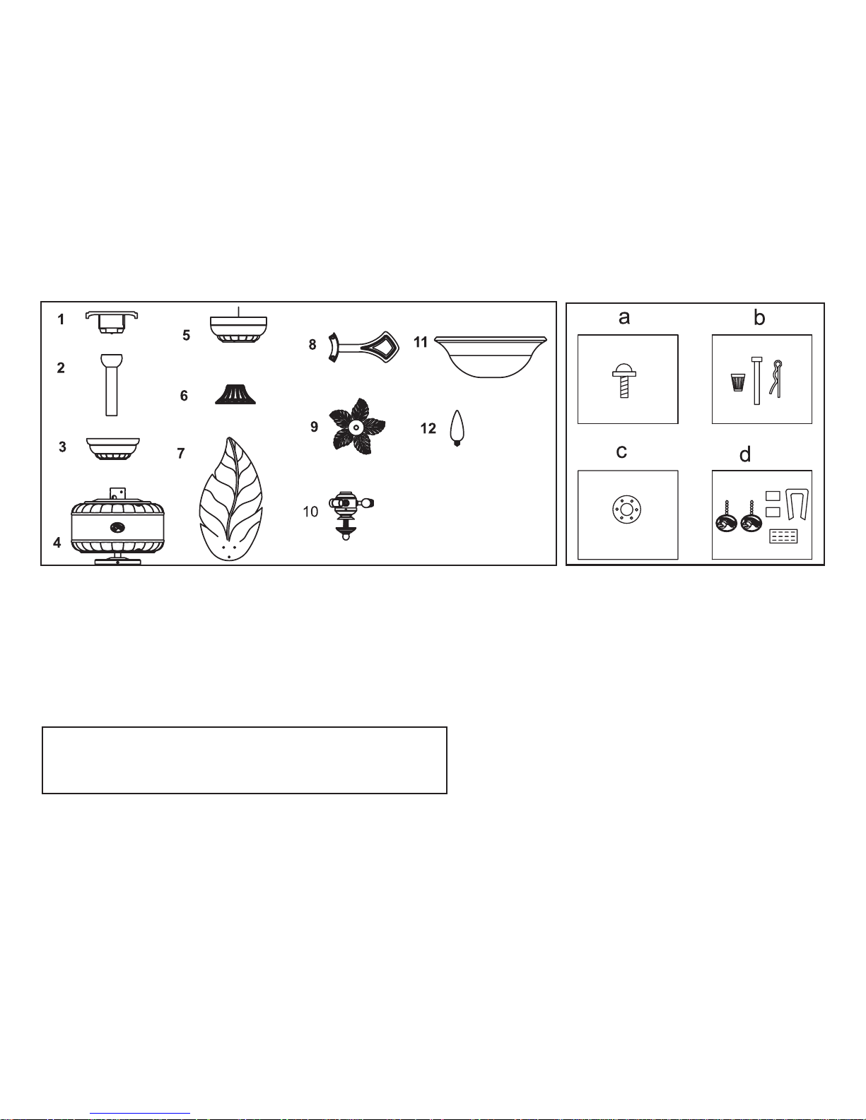
a. Blade attachment hardware
(15 screws)
b. Electrical Hardware
(3 plastic wire connectors, 1 hanger pin, 1
locking pin)
c. Close-to-Ceiling mount hardware
(1 rubber gasket)
d. Miscellaneous Parts & Balancing Kit
(2 pull chains, blade balancing kit)
8. Blade Bracket (Flange) Set (5)
with blade bracket screws pre-installed
9. Decorative Leaves
10. Light Kit
11. Glass Bowl
12. Bulbs (3)
1. Slide-On Mounting Plate (inside canopy)
2. Downrod and Hanger Ball Assembly
3. Canopy with Canopy Ring attached
4. Fan Motor Assembly
5. Switch Housing
6. Decorative Motor Collar Cover
7. Blades (5)
2. Unpacking Your Fan
IMPORTANT: THIS PRODUCT AND/OR COMPONENTS ARE COVERED BY
ONE OR MORE OF THE FOLLOWING U.S. PATENTS: 5,947,436; 5,988,580;
5,971,573; 6,010,110; 6,010,306; 6,039,541; 6,046,416 AND OTHER
PATENTS PENDING.
Unpack your fan and check the contents. You should have the following items:
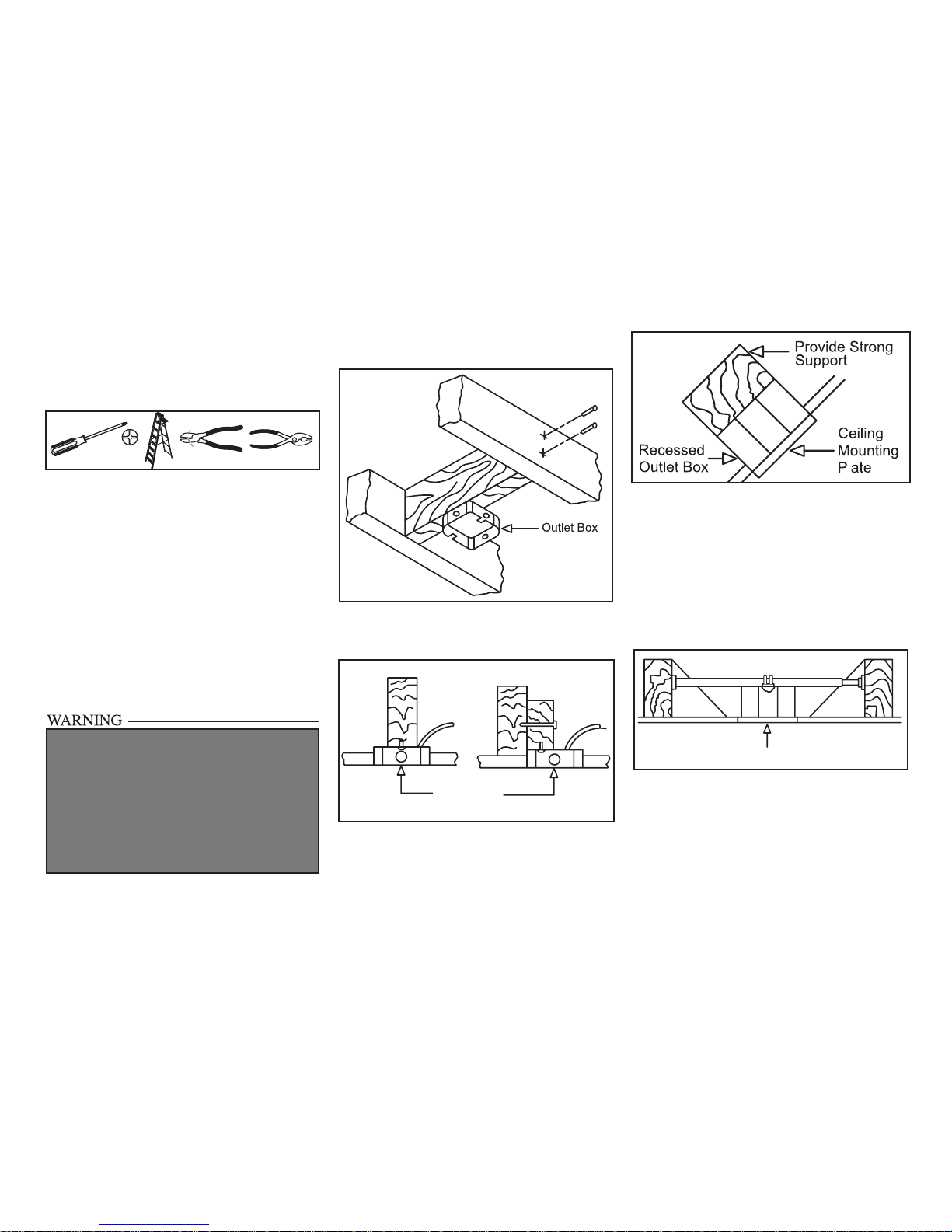
Installing Your Fan 3.
Tools Required
Phillips screw driver, straight slot screw
driver, adjustable wrench, step ladder, and
wire cutters.
Mounting Options
If there isn’t an existing outlet box, then read
the following instructions. Disconnect the
power by removing fuses or turning off
circuit breakers.
Secure the outlet box directly to the building
structure. Use appropriate fasteners and
building materials. The outlet box and its
support must be able to fully support the
moving weight of the fan (at least 35 lbs.)
Do not use plastic outlet boxes.
Figures 1, 2, and 3 are examples of different
ways to mount the outlet box.
Outlet Box
Note: You may need a longer downrod to
maintain proper blade clearance when installing on a steep, sloped ceiling. The maximum
angle allowable is 30˚. If the canopy touches
downrod, remove the decorative canopy
bottom cover and turn the canopy 180˚ before
attaching the canopy to the mounting plate.
Outlet Box
To hang your fan where there is an existing
xture but no ceiling joist, you may need an
installation hanger bar as shown in Figure 4
(available at your Hampton Bay retailer).
TO REDUCE THE RISK OF FIRE, ELECTRIC
SHOCK OR PERSONAL INJURY, MOUNT FAN
ONLY TO AN OUTLET BOX MARKED ACCEPTABLE FOR FAN SUPPORT AND USE THE
MOUNTING SCREWS PROVIDED WITH THE OUTLET BOX. OUTLET BOXES COMMONLY USED
FOR THE SUPPORT OF LIGHTING FIXTURES
MAY NOT BE ACCEPTABLE FOR FAN SUPPORT
AND MAY NEED TO BE REPLACED. CONSULT A
LICENSED ELECTRICIAN IF IN DOUBT.
Figure 1
Figure 2
Figure 4
Figure 3
 Loading...