

HAMPTON BAY Ansley, Ansley 761 512 Owner's Manual
Ansley
52
in Ceiling Fan
Owner’s Manual
Ansley
Ventilador de Techo de 1,32
m
Manual del Propietario
761 512

52” Ansley
Ceiling Fan by Hampton Bay
Date Purchased
Store Purchased
UL Model No.
Serial No.
Vendor No.
UPC
Thank you for purchasing our ceiling fan. This product has been
manufactured with the highest standards of safety and quality.
Table of Contents
Safety Rules . . . . . . . . . . . . . . . . . . . . 1
Unpacking Your Fan . . . . . . . . . . . . . . 2
Installing Your Fan . . . . . . . . . . . . . . . 3
Operating Your Transmitter . . . . . . . . . 11
Care of Your Fan . . . . . . . . . . . . . . . . 13
Troubleshooting . . . . . . . . . . . . . . . . . 13
Specifications . . . . . . . . . . . . . . . . . . 14
Warranty Information . . . . . . . . . . . . 15
761-512
11289
792145352792

Safety Rules - Read and Save These Instructions
1
To reduce the risk of electric shock, insure electricity has been turned off
at the circuit breaker or fuse box before beginning.
All wiring must be in accordance with the National Electrical Code
“ANSI/NFPA 70-1999” and local electrical codes. Electrical installation
should be performed by a qualified licensed electrician.
WARNING: To reduce the risk of electrical shock or fire, do not use this
fan with any solid-state fan speed control device. It will permanently
damage the electronic circuitry.
CAUTION: To reduce the risk of personal injury, use only the screws
provided with the outlet box.
The outlet box and support structure must be securely mounted and
capable of reliably supporting a minimum of 35 pounds, Use only UL
Listed outlet boxes marked “FOR FAN SUPPORT.”
The fan must be mounted with a minimum of 7 feet clearance from the
trailing edge of the blades to the floor.
Avoid placing objects in path of the blades.
To avoid personal injury or damage to the fan and other items, be
cautious when working around or cleaning the fan.
Do not use water or detergents when cleaning the fan or fan blades. A dry
dust cloth or lightly dampened cloth will be suitable for most cleaning.
After making electrical connections, spliced conductors should be turned
upward and pushed carefully up into outlet box. The wires should be
spread apart with the grounded conductor and the equipment-grounding
conductor on one side of the outlet box and ungrounded conductor on the
other side of the outlet box.
All set screws must be checked and retightened where necessary before
installation.
1.
2.
3.
4.
5.
6.
7.
8.
9.
10.
11.
WARNING
WARNING
TO REDUCE THE RISK OF PERSONALL INJURY, DO NOT BEND THE
BLADE ARMS (ALSO REFERRED TO AS FLANGES), WHEN
INSTALLING THE BRACKETS, BALANCING THE BLADES OR
CLEANING THE FAN. DO NOT INSERT FOREIGN OBJECTS IN –
BETWEEN ROTATING FAN BLADES.
TO REDUCE THE RISK OF FIRE, ELECTRIC SHOCK OR PERSONAL
INJURY, MOUNT FAN TO OUTLET BOX MARKED ACCEPTABLE FOR
FAN SUPPORT WITH THE SCREWS PROVIDED WITH THE OUTLET
BOX.
2
Unpacking Your Fan
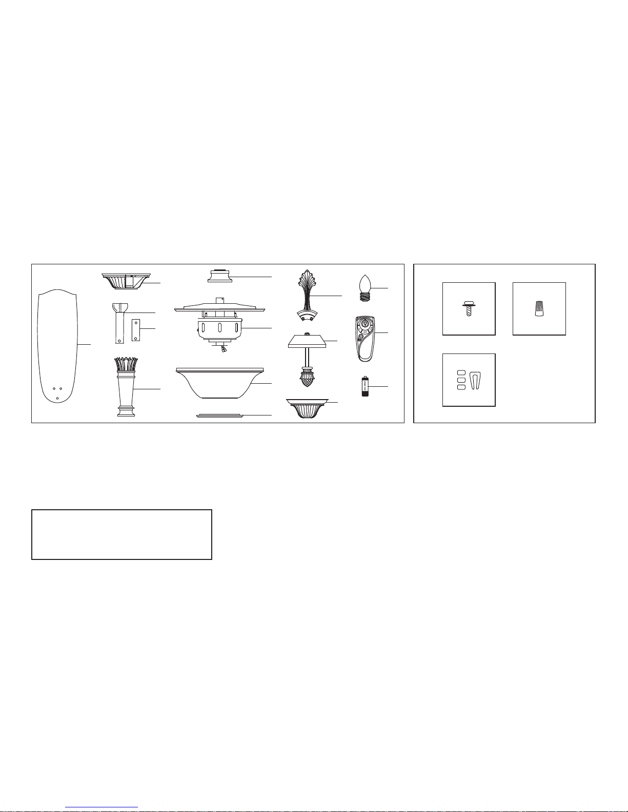
Unpack your fan and check the contents. You should have the following items:
AB
C
1
2
3b
4
5
9
10
11
12
13
14
6
7
8
3a
Set of blades (5)
Canopy assembly
Standard downrod assembly
Minimum-length downrod (for close to
ceiling mounting only)
Arrow style decorative downrod
1.
2.
3a.
3b.
4.
Coupling cover (for close to ceiling
mounting)
Fan motor assembly
Glass housing
Glass housing plate
Blade arms (5)
Decorative plate with nut
Decorative cover
15 Watt candelabra bulbs (6)
Transmitter+holder+2 mounting screws
12V MN21/A23 battery
5.
6.
7.
8.
9.
10.
11.
12.
13.
14
Blade Attachment Hardware
(16 Screws with Fiber Washers)
Electrical Hardware
(3 Plastic Wire Nuts)
Balance Kit
A.
B.
C.
WARNING
DO NOT INSTALL OR USE FAN IF ANY
PART IS DAMAGED OR MISSING.
CALL TOLL FREE 1-877-898-1881.
3
Installing Your Fan
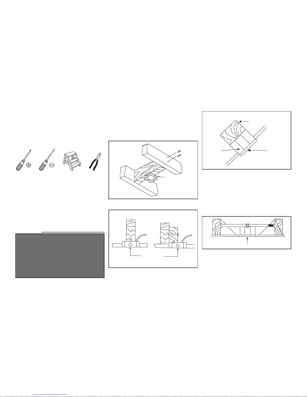
Figures 1~3 are examples of different ways to
mount the outlet box.
If there isn't an existing UL listed mounting box,
then read the following instructions. Disconnect
the power by removing fuses or turning off circuit
breakers.
Secure the outlet box directly to the building
structure. Use appropriate fasteners and building
materials. The outlet box and its support must be
able to fully support the moving weight of the fan
(at least 35 lbs). Do not use plastic outlet boxes.
Tools Required
Mounting Options
WARNING
TO REDUCE THE RISK OF FIRE, ELECTRIC
SHOCK OR PERSONAL INJURY, MOUNT FAN
ONLY TO AN OULET BOX MARKED ACCEPTABLE FOR FAN SUPPORT AND USE THE
MOUNTING SCREWS PROVIDED WITH THE
OULET BOX. OUTLET BOX COMMONLY USED
FOR THE SUPPORT OF LIGHTING FIXTURE
MAY NOT BE ACCEPTABLE FOR FAN SUPPORT
AND MAY NEED TO BE REPLACED. CONSULT A
QUALIFIED ELECTRICIAN IF IN DOUBT.
Outlet Box
Outlet Box
Outlet Box
Figure 2
Figure 1
Note: You may need a longer downrod to
maintain proper blade clearance when installing
on a steep, sloped ceiling. The maximum angle
allowable is 24°. If the canopy touches downrod,
remove the decorative canopy bottom cover and
turn the canopy 180° before attaching the canopy
to the mounting plate.
To hang your fan where there is an existing fixture
but no ceiling joist, you may need an installation
hanger bar as shown in Figure 4 (available at any
Home Depot store).
Ceiling
Mounting
Plate
Provide Strong
Support
Recessed
Outlet Box
Figure 3
Figure 4
Phillips screwdriver, straight slot screwdriver, step
ladder and wire cutters.
4
REMEMBER to turn off the power. Follow the
steps below to hang your fan properly.
NOTE: Your fan comes with a 13" downrod
attached to the hanging ball to use with the arrow
style decorative downrod (See Fig. 6). In addition,
you have been provided with a 4-1/2" downrod to
use on lower ceilings without decorative arrow
downrod cover. ( See Fig. 6A)
Installing the fan with the arrow style
decorative downrod (with 13" downrod)
(Recommend min. 9 ft. ceiling height).
Follow the Figure 6 and continue on section titled
"Hanging the Fan" for installation.
Hanging the Fan
CHANGING THE DOWNROD
WARNING
FAILURE TO PROPERLY INSTALL COTTER PIN
AS NOTED IN STEP 5 COULD RESULT IN FAN
LOOSENING AND POSSIBLY FALLING.
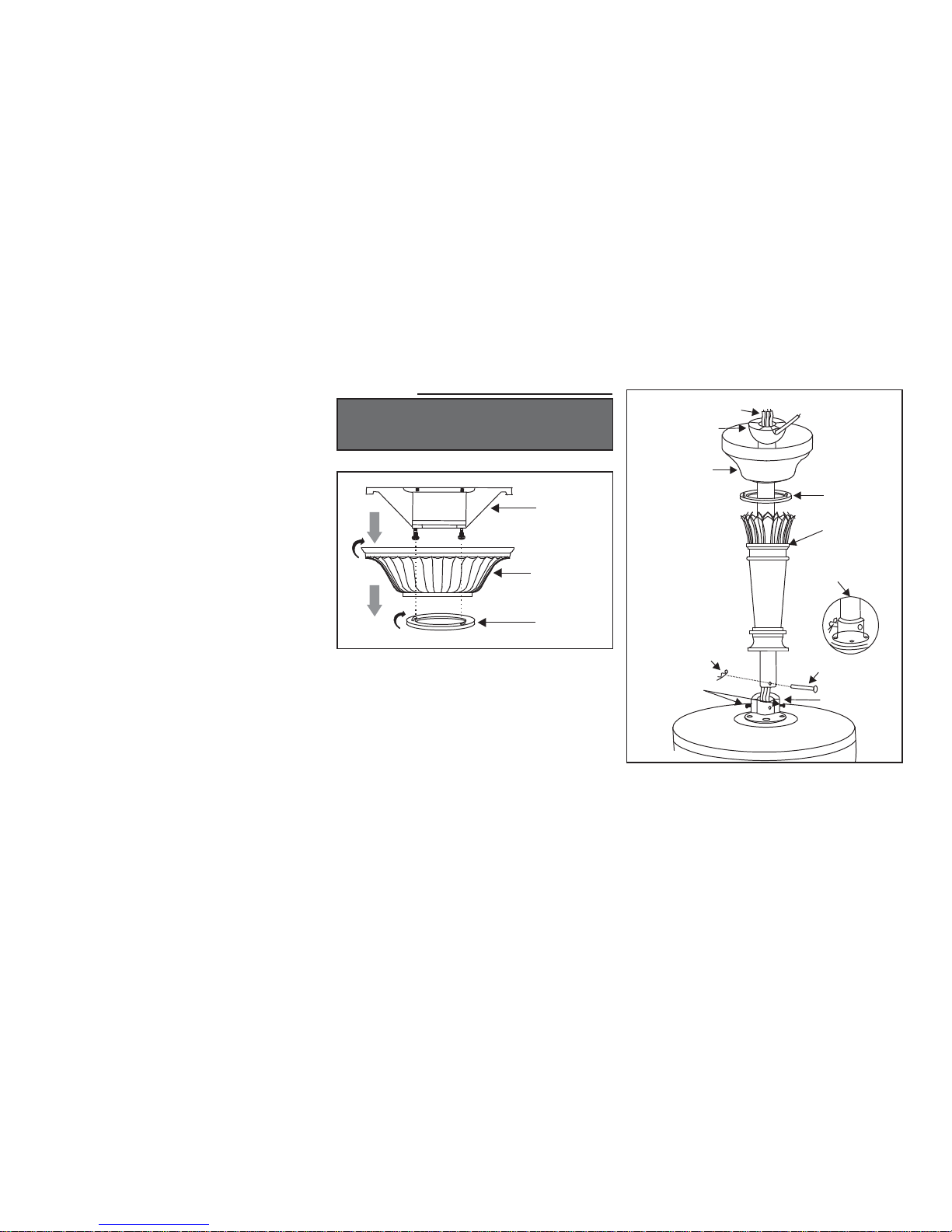
Tighten two set screws at top of the fan motor
collar firmly and evenly. (Fig. 6)
6.
Remove the decorative canopy bottom cover
from the canopy by turning the cover clockwise.
(Figure 5)
Remove the mounting bracket from the canopy
by loosening the two screws on the bottom of
the mounting bracket a half turn from the screw
head and turning the canopy clockwise.
(Figure 5)
Remove the clevis pin, cotter pin and set
screws from the top of the motor assembly.
(Figure 6)
Route wires exiting from the top of the fan
motor through the coupling cover, canopy
cover, canopy and then through the ball/
downrod. (Figure 6)
Align the holes at the bottom of the downrod
with the holes in the coupling on top of the
motor housing (Figure 6). Carefully insert the
clevis pin through the holes in the collar and
downrod. Be careful not to jam the clevis pin
against the wiring inside the downrod. Insert
the cotter pin through the hole near the end of
the clevis pin until it snaps into its locked
position, as noted in the circle inset of Fig. 6.
1.
2.
3.
4.
5.
Figure 5
Figure 6
Ceiling
Mounting
Bracket
Ceiling Canopy
Canopy Bottom
Cover
Motor Collar
Canopy Bottom
Cover
Ball/Downrod
Assembly
Ceiling Canopy
Tighten Screw
Firmly
Motor Wires
Arrow Style
Decorative
Downrod
With 13" Downrod
Pin in Locked
Positioon
Cotter Pin
Clevis Pin
 Loading...