

HAMPTON BAY AL975-BN 593-552 Use And Care Manual
THANK YOU
Item #593-552
Model #AL975-BN
USE AND CARE GUIDE
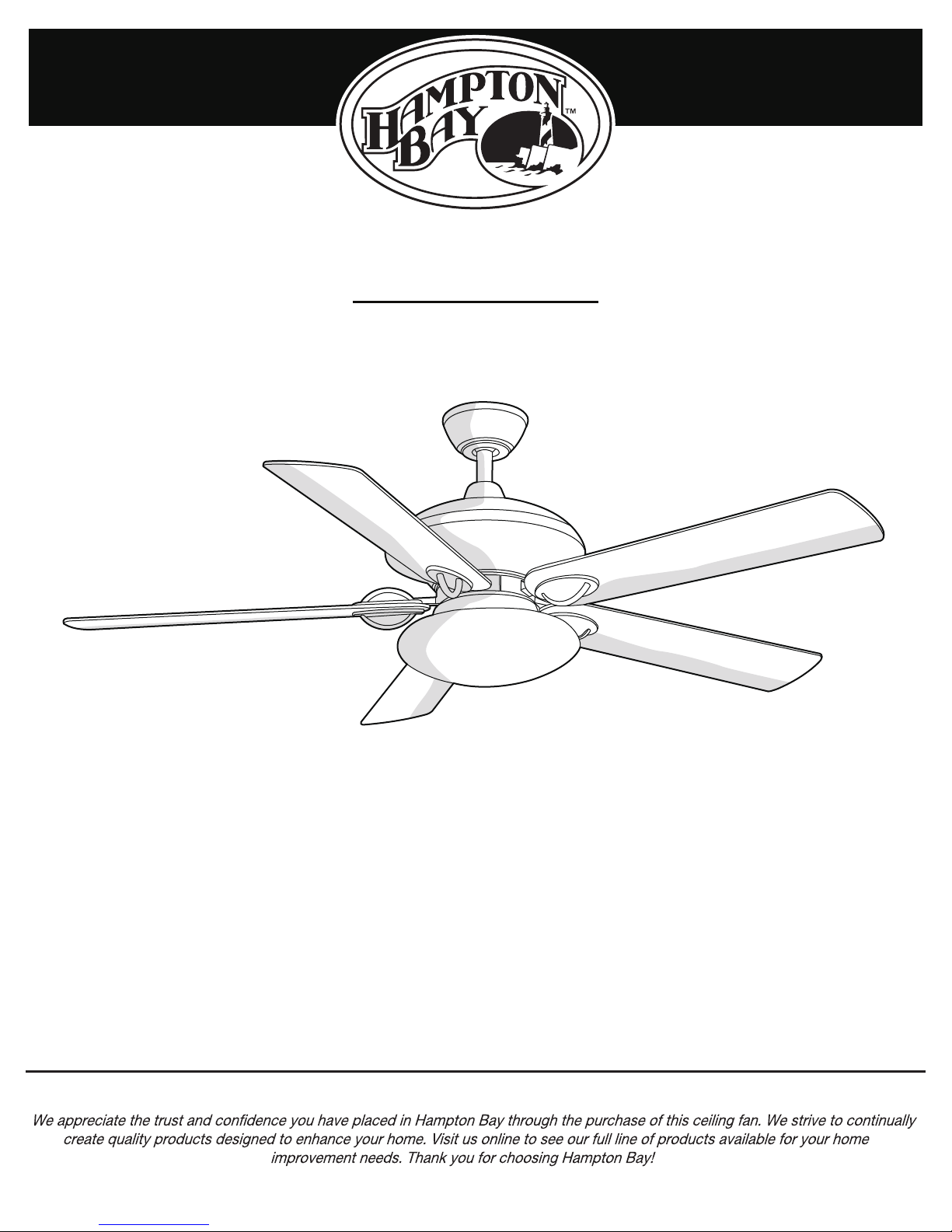
SAUTERNE II 52 INCH CEILING FAN
Questions, problems, missing parts? Before returning to the store,
call Hampton Bay Customer Service
8 a.m. - 6 p.m., EST, Monday-Friday
1-877-527-0313
HAMPTONBAY.COM
THANK YOU

Table of Contents
Table of Contents ..........................................................
Safety Information .........................................................
Warranty .........................................................................
Pre-installation ..............................................................
Specifications ..........................................................................
Tools Required .........................................................................
Hardware Included ..................................................................
Package Contents ....................................................................
Installation .....................................................................
Assembly ........................................................................
Assembling the Fan Body..........................................................
Hanging the Fan .......................................................................
Preparing the Remote Control ................................................
Making Electrical Connections ...............................................
Completing the Fan Body .......................................................
Attaching the Fan Blades .......................................................
Installing the Light Kit ............................................................
10
11
12
13
14
2
3
4
4
4
4
5
6
7
8
8
9
Operation ......................................................................
Remote Control Operating Instructions ..................................
Installing the Remote Control Holder .....................................
Reverse Switch Operating Instructions ..................................
Care and Cleaning .......................................................
Troubleshooting ..........................................................
Service Parts ...............................................................
16
16
16
17
17
18
19
2
Safety Information
1. To reduce the risk of electric shock, ensure electricity has
been turned off at the circuit breaker or fuse box before
beginning.
2. All wiring must be in accordance with the National Electrical
Code “ANSI/NFPA 70-1999” and local electrical codes.
Electrical installation should be performed by a qualified
licensed electrician.
3. The outlet box and support structure must be securely
mounted and capable of reliably supporting a minimum of 35
lbs. Use only UL-listed outlet boxes marked “FOR FAN
SUPPORT.”
4. The fan must be mounted with a minimum of 7 ft. clearance
from the trailing edge of the blades to the floor.
5. Avoid placing objects in the path of the blades.
6. To avoid personal injury or damage to the fan and other
items, be cautious when working around or cleaning the fan.
7. Do not use water or detergents when cleaning the fan or fan
blades. A dry dust cloth or lightly dampened cloth will be
suitable for most cleaning.
WARNING: To reduce the risk of electrical shock or fire, do
not use this fan with any solid-state fan speed control device.
It will permanently damage the electronic circuitry.
WARNING: To reduce the risk of personal injury, do not
bend the blade arms (also referred to as flanges), when
installing the brackets, balancing the blades, or cleaning the
fan.
WARNING: Do not insert foreign objects between rotating
fan blades.
WARNING: To reduce the risk of fire, electric shock, or
personal injury, mount the fan to the outlet box marked
acceptable for fan support with the screws provided with the
outlet box.
CAUTION: To reduce the risk of personal injury, use only
the screws provided with the outlet box.
8. After making electrical connections, spliced conductors
should be turned upward and pushed carefully up into the
outlet box. The wires should be spread apart with the
grounded conductor and the equipment-grounding conductor
on one side of the outlet box and ungrounded conductor on
the other side of the outlet box.
9. All setscrews must be checked and retightened where
necessary before installation.
NOTICE: This fan includes a 190W limiter to comply with the
department of energy 2009 regulation. Lamping this product over
190W will cause this fan to not light. Please use bulbs with a total
wattage under the 190W regulation.
3 HAMPTONBAY.COM
Please contact 1-877-527-0313 for further assistance.

SPECIFICATIONS
TOOLS REQUIRED
Warranty
Fan size
Watts
RPM
CFM
Speed
Volts
Amps
N.W.
G.W.
C.F.
We warrant the fan motor to be free from defects in workmanship and material present at time of shipment from the factory for a period
of lifetime after the date of purchase by the original purchaser. We also warrant that all other fan parts, excluding any glass or acrylic
blades, to be free from defects in workmanship and material at the time of shipment from the factory for a period of one year after the
date of purchase by the original purchaser. We agree to correct such defects without charge or at our option replace with a comparable or
superior model if the product is returned. To obtain warranty service, you must present a copy of the receipt as proof of purchase. All
costs of removing and reinstalling the product are your responsibility. Damage to any part such as by accident, misuse, improper installation or by affixing any accessories, is not covered by this warranty. Because of varying climatic conditions this warranty does not cover
any changes in brass finish, including rusting, pitting, corroding, tarnishing or peeling. Brass finishes of this type give their longest useful
life when protected from varying weather conditions. A certain amount of “wobble” is normal and should not be considered a defect.
Servicing performed by unauthorized persons shall render the warranty invalid. There is no other express warranty. We hereby disclaim
any and all warranties, including but not limited to those of merchantability and fitness for a particular purpose to the extent permitted by
law. The duration of any implied warranty which cannot be disclaimed is limited to the time period as specified in the express warranty.
Some states do not allow limitation on how long an implied warranty lasts, so the above limitation may not apply to you. The retailer shall
not be liable for incidental, consequential, or special damages arising out of or in connection with product use or performance except as
may otherwise be accorded by law. Some states do not allow the exclusion of incidental or consequential damages, so the above
exclusion or limitation may not apply to you. This warranty gives specific legal rights, and you may also have other rights which vary from
state to state. This warranty supersedes all prior warranties. Shipping costs for any return of product as part of a claim on the warranty
must be paid by the customer.
Contact the Customer Service Team at 1-877-527-0313 or visit www.hamptonbay.com.
Pre-InstallationPre-Installation
SPECIFICATIONS
Fan size
52 in.
TOOLS REQUIRED
Speed
Low
Medium
High
NOTE: These are approximate measures. They do not
include amps and wattage used by the light kit.
Phillips
screwdriver
Volts
120
Flat blade
screwdriver
Amps
0.36
0.50
0.58
Watts
12.27
30.19
70.09
RPM
62
109
174
Step
ladder
CFM
1794.26
3255.24
5576.44
10.97 kg
(24.13 lb)
Wire
stripper
N.W.
G.W.
12.32 kg
(27.10 lb)
C.F.
2.49 ft.
Electrical
Tape
4
Pre-Installation (continued)
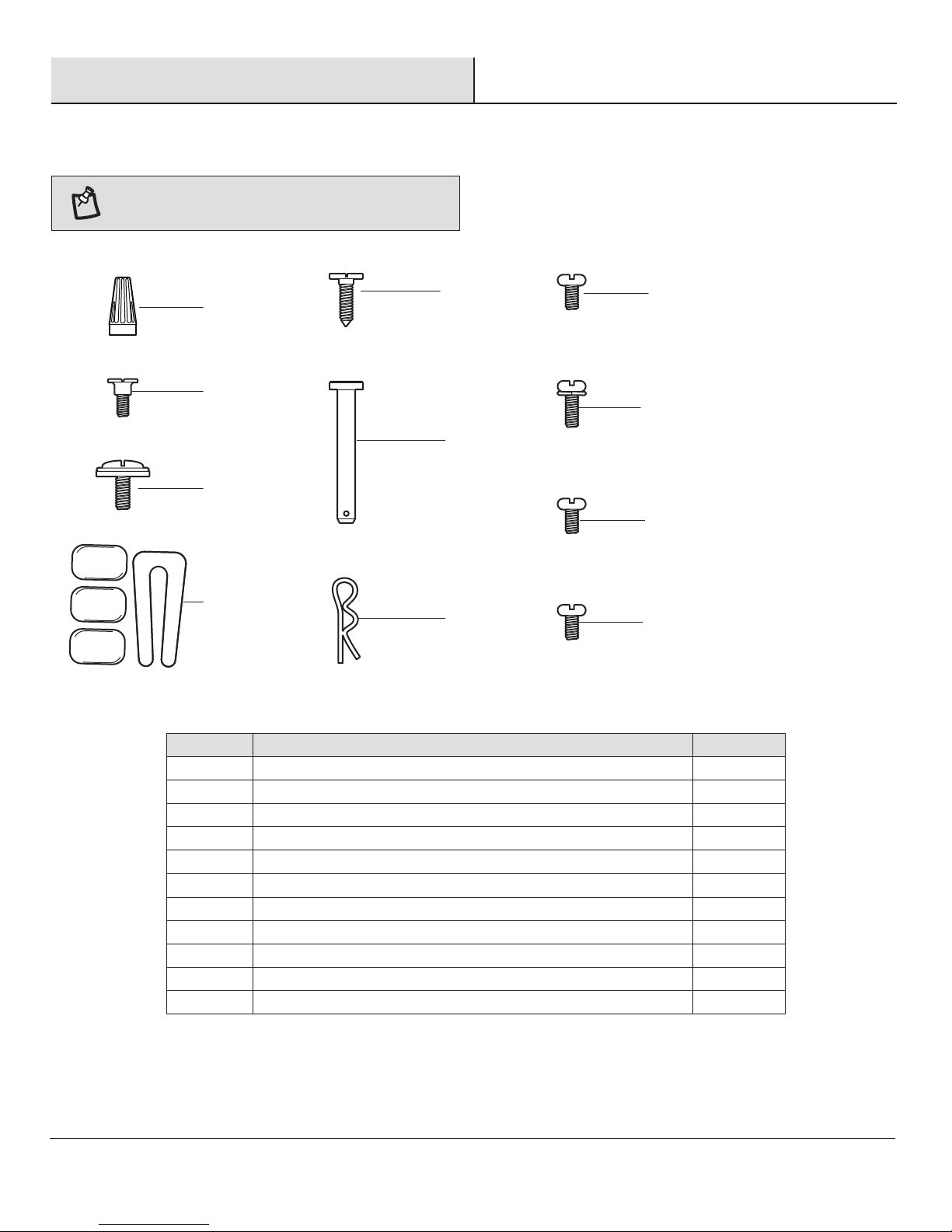
HARDWARE INCLUDED
Part
Description
Quantity
HARDWARE INCLUDED
NOTE: Hardware shown to actual size unless noted
otherwise in the table below.
AA
BB
CC
DD
EE
FF
GG
HH
II
JJ
KK
Part
AA
BB
CC
DD
EE
FF
GG
HH
II
JJ
KK
Description
Plastic wire nut
Mounting bracket screw (preassembled)
Blade attachment screw and fiber washer
Balance kit (not to scale)
Remote control holder mounting screw
Clevis pin (preassembled)
Cotter pin (preassembled)
Collar setscrew (preassembled)
Blade arm screw (preassembled)
Light kit mounting plate screw (preassembled)
Light kit mounting screw (preassembled)
5 HAMPTONBAY.COM
Quantity
9
2
21
1
2
1
1
2
10
3
3
Please contact 1-877-527-0313 for further assistance.
Part
Description
Part
Quantity
Description
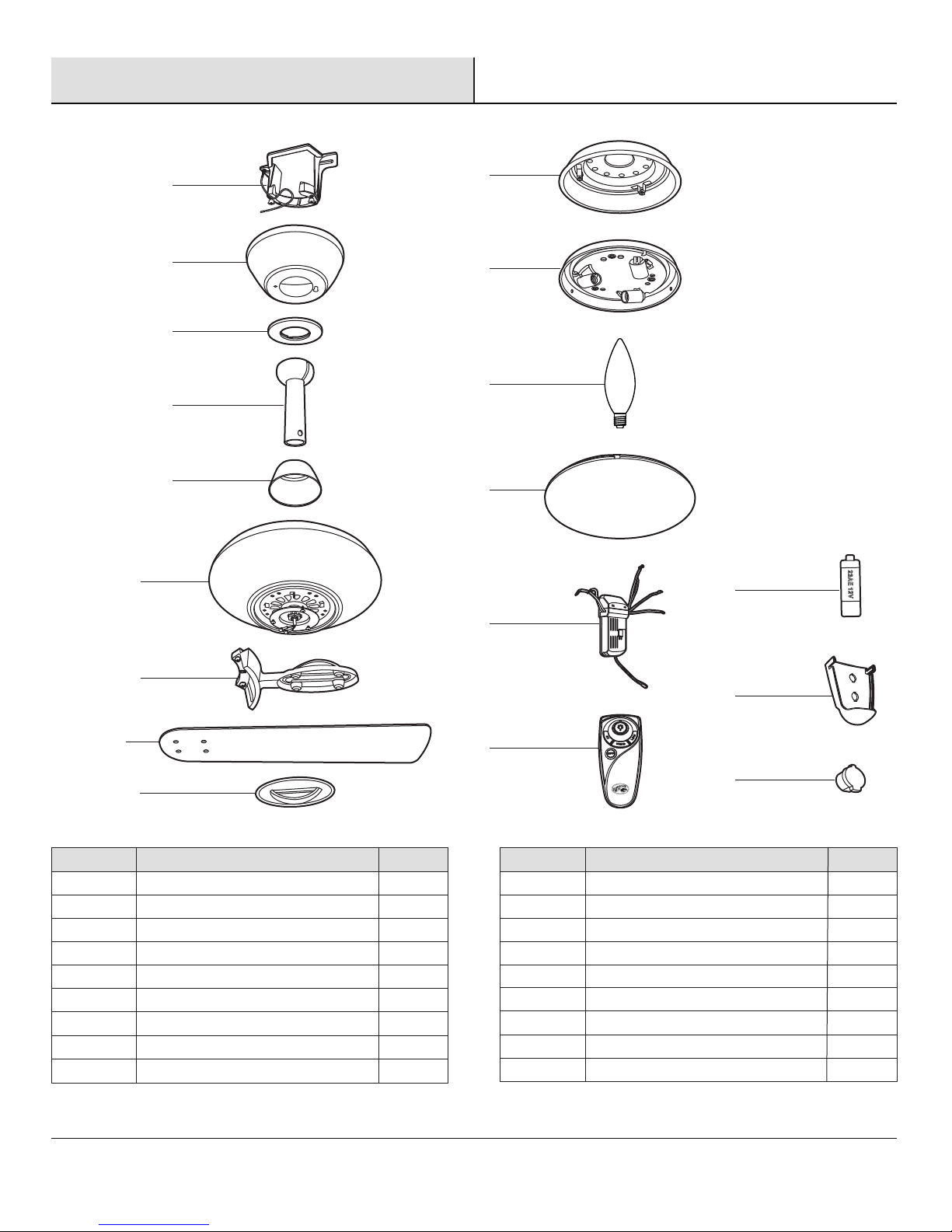
PACKAGE CONTENTS
Quantity
Pre-Installation (continued)
PACKAGE CONTENTS
A
B
C
D
E
F
J
K
L
M
P
N
Part
A
B
C
D
E
F
G
H
I
G
H
I
Description
Mounting bracket (preassembled)
Canopy
Canopy bottom cover
Hanger ball/downrod assembly
Coupling cover
Fan motor assembly
Blade arm
Blade
Blade medallion
Quantity
1
1
1
1
1
1
5
5
5
Q
O
R
Part
J
K
L
M
N
O
P
Q
R
Description
Light kit mounting plate
Light kit
40 Watt candelabra bulb
Glass shade
Receiver
Remote control
12V MN21/A23 battery
Remote control holder
Remote control holder plug
Quantity
1
1
3
1
1
1
1
1
2
6
 Loading...