

HAMPTON BAY AG524-ORB Use And Care Manual
THANK YOU
Model #
USE AND CARE GUIDE
GLENDALE 52 INCH CEILING FAN
Item #xxx-xxx
AG524-ORB
Questions, problems, missing parts? Before returning to the store call
Hampton Bay Customer Service
8 a.m. - 6 p.m., EST, Monday-Friday
1-877-527-0313
HAMPTONBAY.COM
THANK YOU
Table of Contents
Table of Contents ..........................................................
Safety Information .........................................................
Warranty .........................................................................
Pre-Installation ..............................................................
Tools Required .........................................................................
Hardware Included ..................................................................
Package Contentd ....................................................................
Dual Mounting Instruction ........................................................
Installation .....................................................................
Assembly ........................................................................
Standard Ceiling Mounting .......................................................
Close-to-Ceiling Mounting .....................................................
Hanging the Fan ....................................................................
Attaching the Fan Blades .......................................................
Installing the Light Kit ............................................................
10
11
14
15
2
3
4
4
4
4
5
6
7
8
9
9
Operation .....................................................................
Pull Chain Operating Instructions ..........................................
Reverse Switch Operating Instructions ..................................
Care and Cleaning .......................................................
Troubleshooting ..........................................................
Service Parts ...............................................................
16
16
16
17
17
19
2
Safety Information
1.
To reduce the risk of electric shock, ensure electricity has
been turned off at the circuit breaker or fuse box before
beginning.
2.
All wiring must be in accordance with the National Electrical
Code “ANSI/NFPA 70-1999” and local electrical codes.
Electrical installation should be performed by a qualified
licensed electrician.
3.
The outlet box and support structure must be securely
mounted and capable of reliably supporting a minimum of 35
pounds. Use only CUL Listed outlet boxes marked “FOR FAN
SUPPORT.”
4.
The fan must be mounted with a minimum of 7 ft. clearance
from the trailing edge of the blades to the floor.
5.
Avoid placing objects in the path of the blades.
6.
To avoid personal injury or damage to the fan and other items,
be cautious when working around or cleaning the fan.
7.
Do not use water or detergents when cleaning the fan or fan
blades. A dry dust cloth or lightly dampened cloth will be
suitable for most cleaning.
WARNING: To reduce the risk of electric shock, ensure
electricity has been turned off at the circuit breaker or fuse
box before beginning.
WARNING: To reduce the risk of electrical shock or fire, do
not use this fan with any solid-state fan speed control device.
It will permanently damage the electronic circuitry.
WARNING: To reduce the risk of personal injury, do not
bend the blade arms (also referred to as flanges), when
installing the brackets, balancing the blades or cleaning the
fan.
WARNING: Do not insert foreign objects in-between rotating
fan blades.
WARNING: To reduce the risk of fire, electric shock or
personal injury, mount the fan to the outlet box marked
acceptable for fan support with the screws provided with the
outlet box.
CAUTION: To reduce the risk of personal injury, use only
the screws provided with the outlet box.
8.
After making electrical connections, spliced conductors
should be turned upward and pushed carefully up into the
outlet box. The wires should be spread apart with the
grounded conductor and the equipment-grounding conductor
on one side of the outlet box and ungrounded conductor on
the other side of the outlet box.
9.
All setscrews must be checked and retightened where
necessary before installation.
NOTICE: Canada's office of energy efficiency requires this fan to be
equipped with a 190 watt limiting device. If lamping exceeds 190
watts, the ceiling fan's light kit will shut off automatically.
3 HAMPTONBAY.COM
Please contact 1-877-527-0313 for further assistance.
Warranty
Fan size
Watts
RPM
CFM
Speed
Volts
Amps
N.W.
G.W.
C.F.
SPECIFICATIONS
TOOLS REQUIRED
We warrant the fan motor to be free from defects in workmanship and material present at time of shipment from the factory for a period
of lifetime after the date of purchase by the original purchaser. We also warrant that all other fan parts, excluding any glass or acrylic
blades, to be free from defects in workmanship and material at the time of shipment from the factory for a period of one year after the
date of purchase by the original purchaser. We agree to correct such defects without charge or at our option replace with a comparable or
superior model if the product is returned. To obtain warranty service, you must present a copy of the receipt as proof of purchase. All
costs of removing and reinstalling the product are your responsibility. Damage to any part such as by accident, misuse, improper installation or by affixing any accessories, is not covered by this warranty. Because of varying climatic conditions this warranty does not cover
any changes in brass finish, including rusting, pitting, corroding, tarnishing or peeling. Brass finishes of this type give their longest useful
life when protected from varying weather conditions. A certain amount of “wobble” is normal and should not be considered a defect.
Servicing performed by unauthorized persons shall render the warranty invalid. There is no other express warranty. We hereby disclaim
any and all warranties, including but not limited to those of merchantability and fitness for a particular purpose to the extent permitted by
law. The duration of any implied warranty which cannot be disclaimed is limited to the time period as specified in the express warranty.
Some states do not allow limitation on how long an implied warranty lasts, so the above limitation may not apply to you. The retailer shall
not be liable for incidental, consequential, or special damages arising out of or in connection with product use or performance except as
may otherwise be accorded by law. Some states do not allow the exclusion of incidental or consequential damages, so the above
exclusion or limitation may not apply to you. This warranty gives specific legal rights, and you may also have other rights which vary from
state to state. This warranty supersedes all prior warranties. Shipping costs for any return of product as part of a claim on the warranty
must be paid by the customer.
Contact the Customer Service Team at 1-877-527-0313 or visit www.hamptonbay.com.
Pre-Installation
SPECIFICATIONS
Fan size
52 in.
TOOLS REQUIRED
Speed
Low
Medium
High
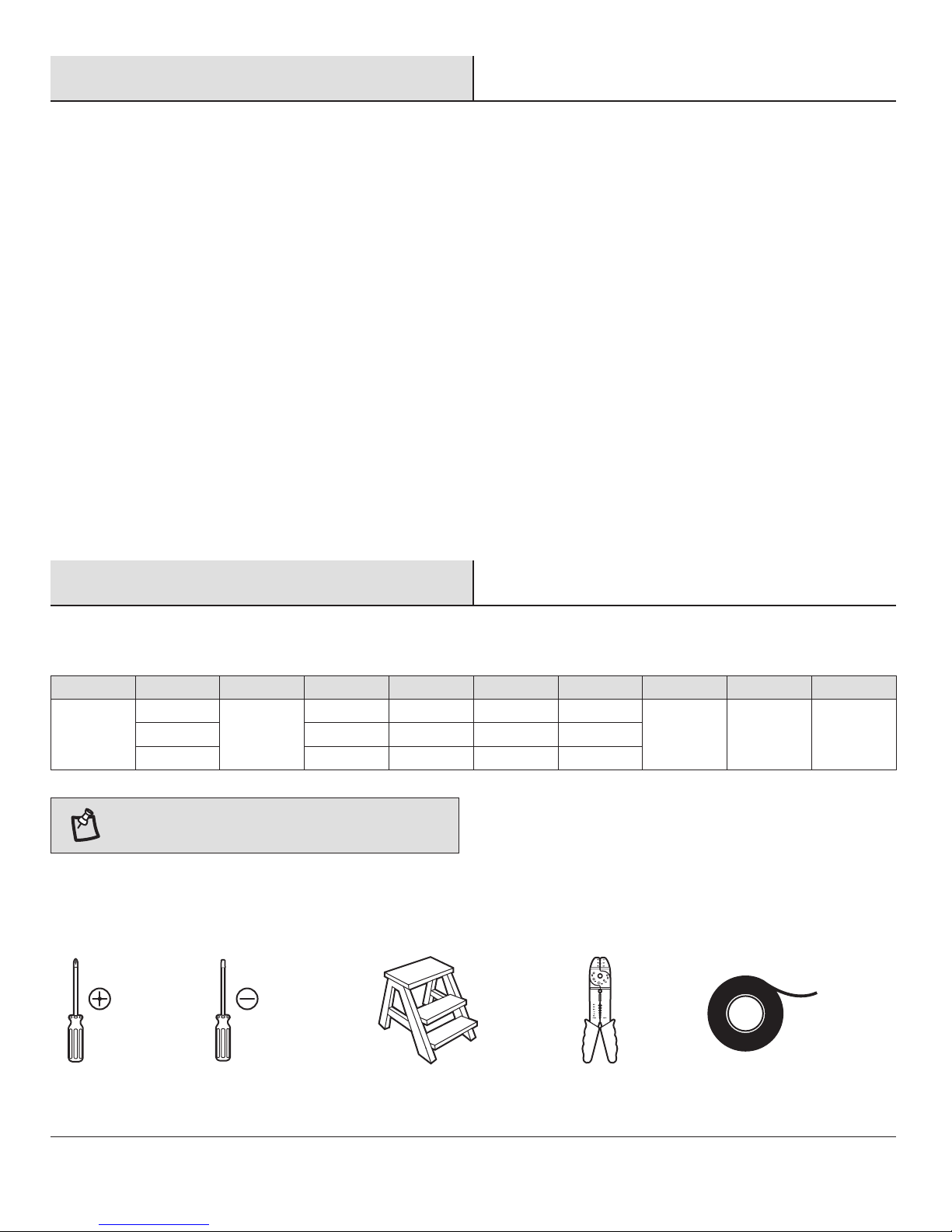
NOTE: These are approximate measures. They do not
include amps and wattage used by the light kit.
Phillips
screwdriver
Volts
120
Flat blade
screwdriver
Amps
0.21
0.37
0.51
Watts
10.3
30.6
61.5
RPM
66
122
172
Step
ladder
CFM
1654
3097
4638
8.5 kg
(18.7 lbs.)
Wire
stripper
N.W.
G.W.
9.2 kg
(20.2 lbs.)
C.F.
1.71 cuft
Electrical
tape
4

Pre-Installation (continued)
HARDWARE INCLUDED
Part
Description
Quantity
HARDWARE INCLUDED
NOTE: Hardware shown to actual size unless noted
otherwise in the table below.
AA
BB
CC
DD
EE
FF
GG
HH
JJ
MM
KK
NN
II
LL
Part
AA
BB
CC
DD
EE
FF
GG
HH
II
JJ
KK
LL
MM
NN
Description
Blade attachment hardware
Mounting hardware
Plastic wire nut
Light holder thumbscrews (preassembled)
Balance kit (not to scale)
Mounting bracket hardware (preassembled)
Clevis pin (preassembled)
Cotter pin (preassembled)
Collar setscrews (preassembled)
Collar mounting screws with lock washers (preassembled)
Blade arm screws
Light kit mounting screws (preassembled)
Pull chains and fobs (not to scale)
Extra switch housing cover (not to scale)
5 HAMPTONBAY.COM
Please contact 1-877-527-0313 for further assistance.
Quantity
16
2
3
10
1
4
1
1
2
6
10
3
2
1
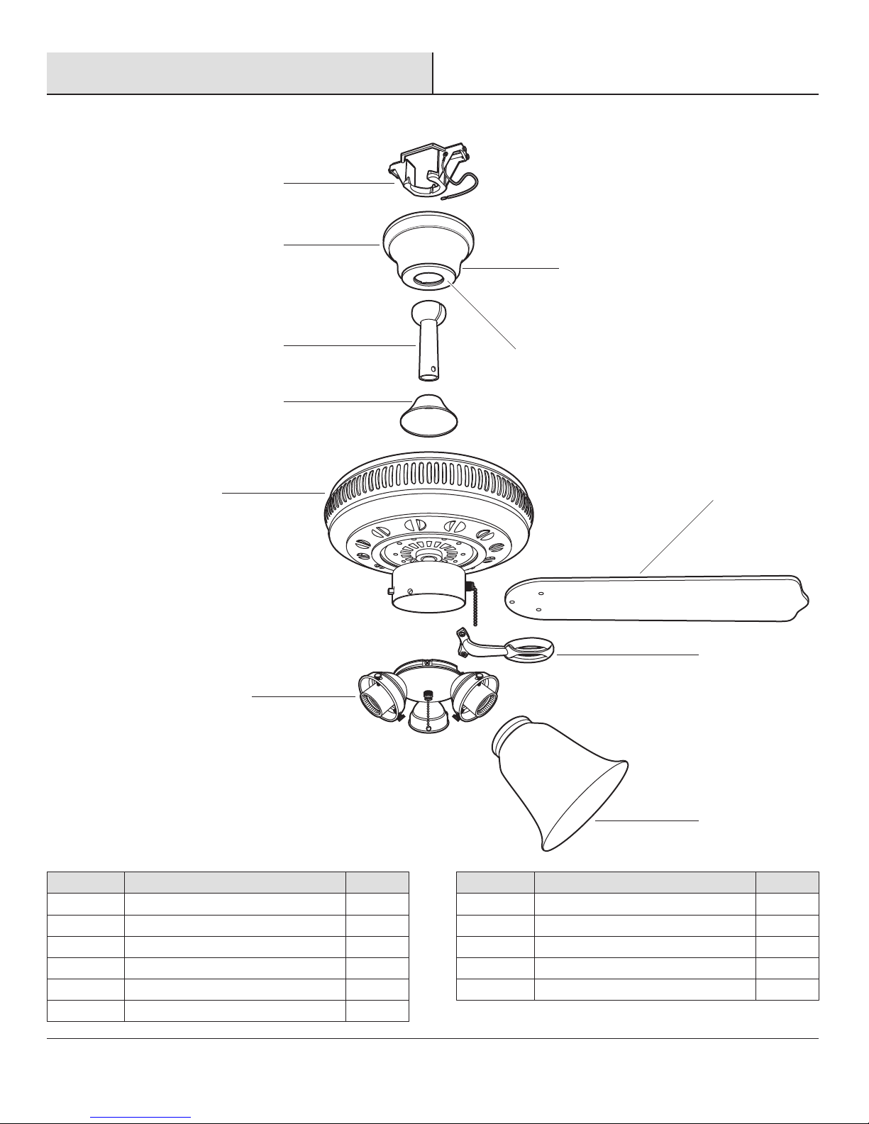
PACKAGE CONTENTS
Part
Description
Pre-Installation (continued)
Part
Quantity
Quantity
Description
PACKAGE CONTENTS
A
B
C
E
F
G
J
D
H
I
Part
A
B
C
D
E
F
Description
Mounting bracket (preassembled)
Canopy ring
Canopy
Canopy bottom cover
Hanger ball/downrod assembly
Coupling cover
Quantity
1
1
1
1
1
1
K
Part
G
H
I
J
K
6
Description
Fan motor assembly
Blades
Blade arms
Light kit
Glass shades
Quantity
1
5
5
1
3
Pre-Installation (continued)
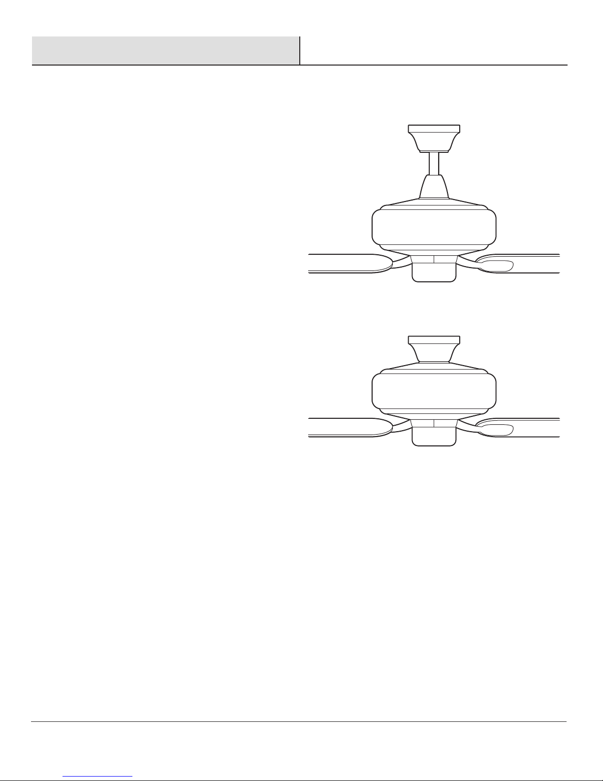
DUAL MOUNTING INSTRUCTIONS
DUAL MOUNTING INSTRUCTIONS
This ceiling fan is supplied with two types of hanging assemblies: the
standard ceiling installation using the downrod with ball and socket
mounting, and the "close-to-ceiling" mounting. The "close-to-ceiling"
mounting is recommended in rooms with less than 8-foot ceilings or in
areas where additional space is desired from the floor to
the fan blades.
When using the standard downrod installation, the distance from the
ceiling to the bottom of the fan blades will be approximately 12 inches.
The "close-to-ceiling" installation reduces the distance from the ceiling to
the bottom of the fan blades to approximately 9 inches.
Once you have decided which ceiling installation you will use, refer to the
corresponding sections and procedures during the assembly period.
Where necessary, each section of the instructions will note the different
procedures to follow for the two types of installation.
Standard Ceiling Mounting
Close-to-Ceiling Mounting
7 HAMPTONBAY.COM
Please contact 1-877-527-0313 for further assistance.
Installation
MOUNTING OPTIONS
MOUNTING OPTIONS
WARNING: To reduce the risk of fire, electric shock, or
personal injury, mount the fan to an outlet box marked
acceptable for fan support using the screws provided with the
outlet box. An outlet box commonly used for the support of
lighting fixtures may not be acceptable for fan support and
may need to be replaced. If in doubt, consult a qualified
electrician.
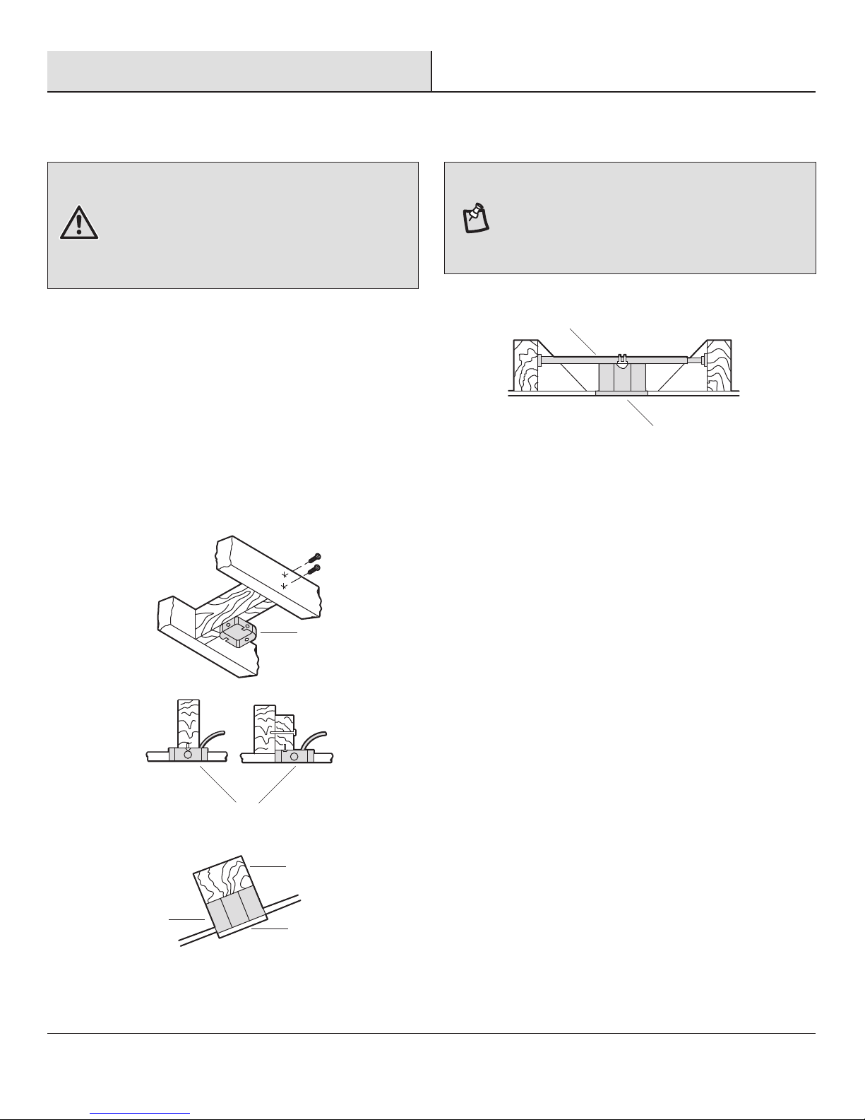
If your ceiling fan does not have an existing CUL-listed mounting
box, then install one using the following instructions:
□ Disconnect the power by removing the fuses or turning off
the circuit breakers.
□ Secure the outlet box (OO) (not included) directly to the
building structure. Use appropriate fasteners and materials
(not included). The outlet box and its bracing must be able
to fully support the weight of the moving fan (at least 35
lbs.). Do not use a plastic outlet box.
The illustrations below show three different ways to mount the
outlet box (OO) (not included).
NOTE: You may need a longer downrod to maintain proper
blade clearance when installing on a steep, sloped ceiling.
The maximum angle allowable is 18° away from horizontal. If
the canopy touches the downrod, then remove the decorative
canopy bottom cover and turn the canopy 180° before
attaching the canopy to the mounting plate.
RR
OO
To hang your fan where there is an existing fixture but no ceiling
joist, you may need an installation hanger bar (RR) (not included)
as shown above.
OO
OO
OO
PP
QQ
8
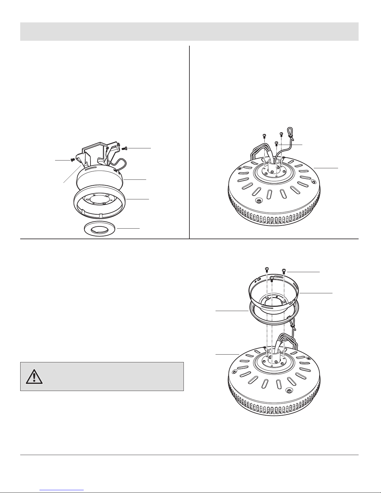
Assembly — Standard Ceiling Mounting
1
Preparing the canopy
□ Remove the canopy ring (B) from the canopy (C).
□ Remove the two non-slotted screws (FF) from the
canopy (C), and loosen the slotted screws (FF) on the
canopy (C).
□ Remove the canopy (C) from the mounting bracket
(A) by turning the canopy (C) counterclockwise.
FF
A
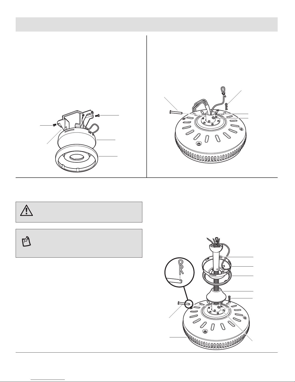
2
Preparing the motor
□ Remove the clevis pin (GG), and cotter pin (HH), and
loosen the two collar setscrews (II) from the motor
collar.
HH
GG
FF
C
B
II
II
3
Assembling the fan
WARNING: Failure to properly install the cotter pin (HH)
could result in the fan becoming loose and possibly falling.
NOTE: If a longer downrod is needed (not included), take
out the screw located in the hanger ball, lower the hanger
ball and remove the pin. Remove all three pieces from the
downrod, and assemble them onto the new longer downrod
before proceeding step 3.
□ Route the wires exiting from the top of the fan motor
assembly (G) through the coupling cover (F) and
canopy ring (B). Ensure the slot openings are on top.
□ Route the wires through the canopy (C) and then
through the hanger ball/downrod assembly (E).
□ Align the holes at the bottom of the hanger
ball/downrod assembly (E) with the holes in the collar
on top of the fan motor assembly (G). Carefully insert
the clevis pin (GG) through the holes in the collar and
the hanger ball/downrod assembly (E). Be careful not
to jam the clevis pin (GG) against the wiring inside the
hanger ball/downrod assembly (E).
□ Insert the cotter pin (HH) through the hole near the
end of the clevis pin (GG) until it snaps into the locked
position.
□ Tighten the two collar setscrews (II) on top of the fan
motor assembly (G) firmly.
E
C
B
F
HH
GG
G
II
9 HAMPTONBAY.COM
Please contact 1-877-527-0313 for further assistance.
Assembly — Close-to-Ceiling Mounting
12
Preparing the motorPreparing the canopy
□ Remove the canopy ring (B) from the canopy (C).
□ Remove the two non-slotted screws (FF) from the
canopy (C), and loosen the slotted screws (FF) on the
canopy (C).
□ Remove the canopy bottom cover (D) from the
canopy (C) by turning the canopy bottom cover (D)
counterclockwise.
FF
FF
C
A
B
D
□ Remove three of the six collar mounting screws with
lock washers (JJ) (every other one) from the collar on
top of the fan motor assembly (G).
JJ
G
3
Assembling the fan
□ Route the wires exiting from the top of the fan motor
assembly (G) through the canopy ring (B).
□ Make sure the slot openings are on top, and then
proceed to place the canopy over the collar at the top
of the fan motor assembly.
□ Align the mounting holes in the bottom of the canopy
(C) with the holes in the top of the fan motor assembly (G), and fasten using the three collar mounting
screws with lock washers (JJ) previously removed.
□ Tighten the collar mounting screws (JJ) securely.
WARNING: Failure to completely tighten the three collar
mounting screws (JJ) could result in the fan becoming loose
and possibly falling.
JJ
C
B
G
10
Assembly — Hanging the Fan
11
HAMPTONBAY.COM
Please contact 1-877-527-0313 for further assistance.
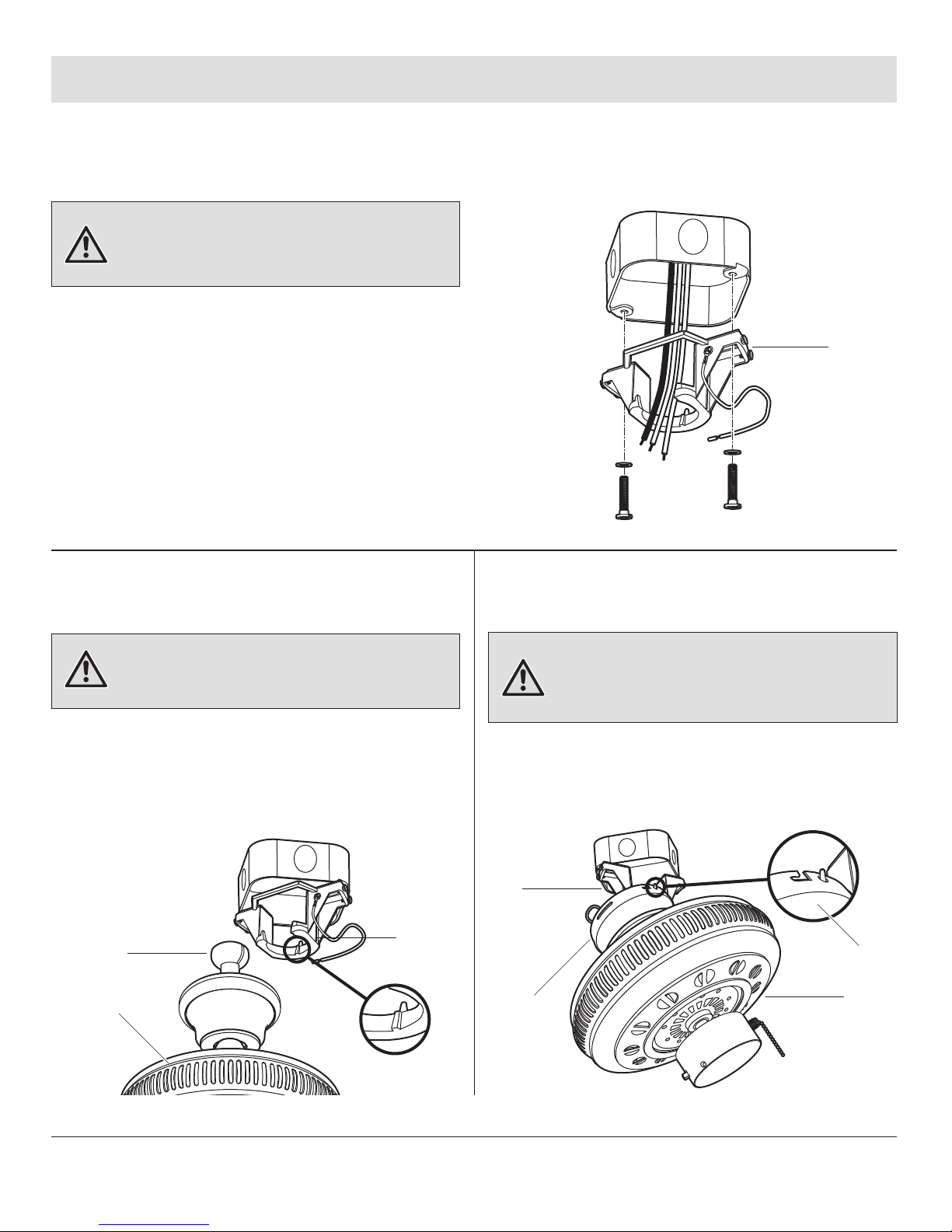
4
Attaching the fan to the
electrical box
5b5a
Hanging instructions for
standard mounting
Hanging instructions for
close-to-ceiling mounting
□ Pass the 120-volt supply wires through the center
hole in the mounting bracket (A).
□ Install the mounting bracket (A) to the outlet box with
the screws and washers provided with your outlet
box. When using “close-to-ceiling” mounting, it is
important that the mounting bracket (A) be level. If
necessary, use leveling washers (not included)
between the mounting bracket (A) and the outlet box.
Note that the flat side of the mounting bracket (A) is
toward the outlet box.
□ Securely tighten the two mounting screws.
WARNING: To reduce the risk of fire, electric shock or
other personal injury, mount the fan only to an outlet box or
supporting system marked acceptable for fan support and
use the mounting screws provided with the outlet box.
WARNING: The tab in the ring must rest in the groove of
the hanger ball (E). Failure to properly seat the tab in the
groove could cause damage to the wiring.
WARNING: The hook is only to hold the fan while attaching
wiring. Failure to hang as instructed may result in the tab
breaking causing the fan to fall. The hook must pass from the
inside to the outside of the canopy.
□ Carefully lift the fan motor assembly (G) up to the
mounting bracket (A) and seat the hanger ball (E) in
the mounting bracket (A) socket. Make sure the tab
on the mounting bracket socket is properly seated in
the groove in the hanger ball (E). This will help to
balance the ceiling fan.
□ Carefully lift the fan motor assembly (G) up to the
mounting bracket (A) and hang the fan on the hook
provided using one of the holes at the outer rim of
the canopy (C).
A
E
G
A
G
C
A
C

Assembly — Hanging the Fan (continued)
Installing the safety cable
6
□ Secure the safety cable (SS) to the building structure
using a wood screw (not included).
SS
SS
Making the electrical
7
connections
WARNING: To avoid possible electrical shock, be sure
electricity is turned off at the main fuse box before wiring.
If you feel you do not have enough electrical wiring
knowledge or experience, have your fan installed by a
licensed electrician.
Follow the steps below to connect the fan to your
household wiring. Use the plastic wire nuts (CC) with your
fan. Secure the wire nuts with electrical tape. Make sure
there are no loose strands or connections.
□ Connect the ground conductor (VV) of the 120V supply
(this may be a bare wire or a wire with green colored
insulation) to the green ground lead(s) (VV) of the fan.
When using standard ceiling mounting, there are two
green grounding leads: one from the mounting
bracket (A) and one from the hanger ball/downrod
assembly (E). When using “close-to-ceiling”
mounting, there is only one green ground lead (VV)
from the mounting bracket (A) since the hanger
ball/downrod assembly (E) is not used.
WARNING: Check to see that all connections are tight,
including ground, and that no bare wire is visible at the wire
nuts (except for the ground wire).
WARNING: To reduce the risk of fire or electric shock, do
not use this fan with any solid-state speed control device.
UU
VV
VV
CC
TT
WW
UU
OO
TT
□ Connect the fan motor white wire (UU) to the supply
white (neutral) wire (UU) using a wire nut.
□ Connect the fan motor black wire (TT) to the supply
black (hot) wire (TT) using a wire nut (CC).
□ Connect the blue wire (WW) for light kit to the black
household supply wire (TT).
□ Turn the wire nut connections upward, spreading
them apart so the green (ground) (VV) will be on one
side of the outlet box (OO) and the white (UU), black
(TT) and blue wire (WW) will be on the other side, and
push carefully up into the outlet box (OO).
12
 Loading...