

HAMPTON BAY AG524I-ORB Use And Care Manual
THANK YOU
Model #
USE AND CARE GUIDE
GLENDALE 52 IN CEILING FAN
Item #3573949
AG524I-ORB
THANK YOU

Table of Contents
Safety Information .........................................................
Warranty .........................................................................
Pre-Installation ..............................................................
Tools Required .........................................................................
Hardware Included ..................................................................
Package Contents ....................................................................
Dual Mounting Instructions ......................................................
Installation .....................................................................
Assembly ........................................................................
Standard Ceiling Mounting .......................................................
Close-to-Ceiling Mounting .....................................................
Hanging the Fan ....................................................................
Attaching the Fan Blades .......................................................
Installing the Light Kit ............................................................
10
11
14
15
3
4
4
4
4
5
6
7
8
9
9
Operation ......................................................................
Pull Chain Operating Instructions ...........................................
Reverse Switch Operating Instructions ..................................
Care and Cleaning .......................................................
Troubleshooting ...........................................................
Service Parts ................................................................
16
16
16
17
17
19
2
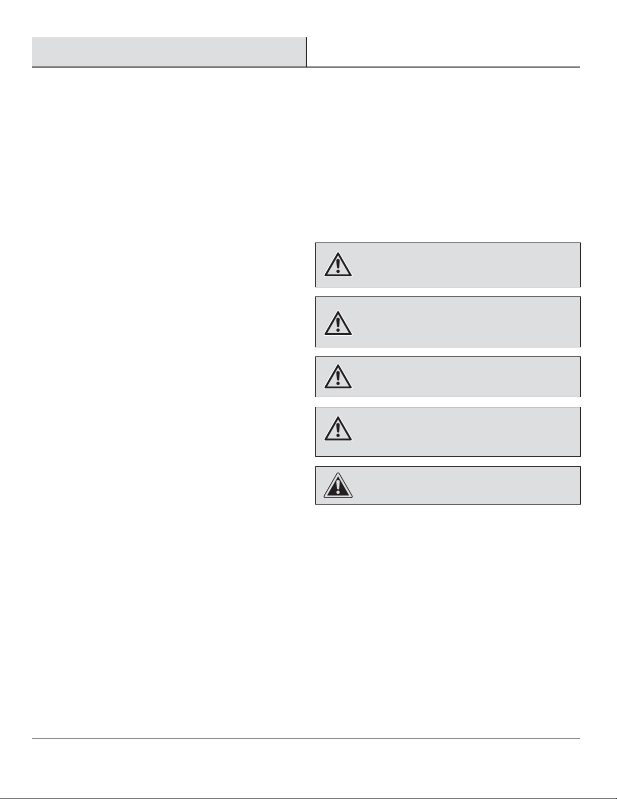
Safety Information
1. To reduce the risk of electric shock, ensure electricity has
been turned off at the circuit breaker or fuse box before
beginning.
2. All wiring must be in accordance with the National Electrical
Code “ANSI/NFPA 70-1999” and local electrical codes.
Electrical installation should be performed by a qualified
licensed electrician.
3. The outlet box and support structure must be securely
mounted and capable of reliably supporting a minimum of 35
lbs. (15.9 kg) or less. Use only UL-listed outlet boxes marked
“FOR FAN SUPPORT.”
4. The fan must be mounted with a minimum of 7 ft. (2.1m)
clearance from the trailing edge of the blades to the floor.
5. Avoid placing objects in the path of the blades.
6. To avoid personal injury or damage to the fan and other
items, be cautious when working around or cleaning the fan.
7. Do not use water or detergents when cleaning the fan or fan
blades. A dry dust cloth or lightly dampened cloth will be
suitable for most cleaning.
However, there is no guarantee that interference will not occur
in a particular installation. If this equipment does cause harmful
interference to radio or television reception, which can be
determined by turning the equipment off and on, the user is
encouraged to try to correct the interference by one or more of
the following measures:
- Reorient or relocate the receiving antenna.
- Increase the separation between the equipment and receiver.
- Connect the equipment into an outlet on a circuit different from
that to which the receiver is connected.
- Consult the dealer or an experienced radio/TV technician for
help.
WARNING: To reduce the risk of electric shock or fire, do
not use this fan with any solid-state fan speed control device.
It will permanently damage the electronic circuitry.
WARNING: To reduce the risk of personal injury, do not
bend the blade arms (also referred to as flanges) when
installing the brackets, balancing the blades, or cleaning the
fan.
WARNING: Do not insert foreign objects between rotating
fan blades.
8. After making electrical connections, spliced conductors
should be turned upward and pushed carefully up into the
outlet box. The wires should be spread apart with the
grounded conductor and the equipment-grounding conductor
on one side of the outlet box and ungrounded conductor on
the other side of the outlet box.
9. All set screws must be checked and retightened where
necessary before installation.
10. This device complies with part 15 of the FCC Rules. Operation
is subject to the following two conditions: (1) This device may
not cause harmful interference, and (2) this device must
accept any interference received, including interference that
may cause undesired operation.
Warning: Changes or modifications to this unit not expressly
approved by the party responsible for compliance could void
the user's authority to operate the equipment.
NOTE: This equipment has been tested and found to comply
with the limits for a Class B digital device, pursuant to Part 15
of the FCC Rules. These limits are designed to provide
reasonable protection against harmful interference in a
residential installation. This equipment generates, uses, and
can radiate radio frequency energy and, if not installed and
used in accordance with the instructions, may cause harmful
interference to radio communications.
WARNING: To reduce the risk of fire, electric shock, or
personal injury, mount the fan to the outlet box marked
acceptable for fan support with the screws provided with the
outlet box.
CAUTION: To reduce the risk of personal injury, use only
the screws provided with the outlet box.
3
Warranty
Fan Size
Watts
RPM
CFM
Speed
Volts
Amps
N.W.
G.W.
C.F.
SPECIFICATIONS
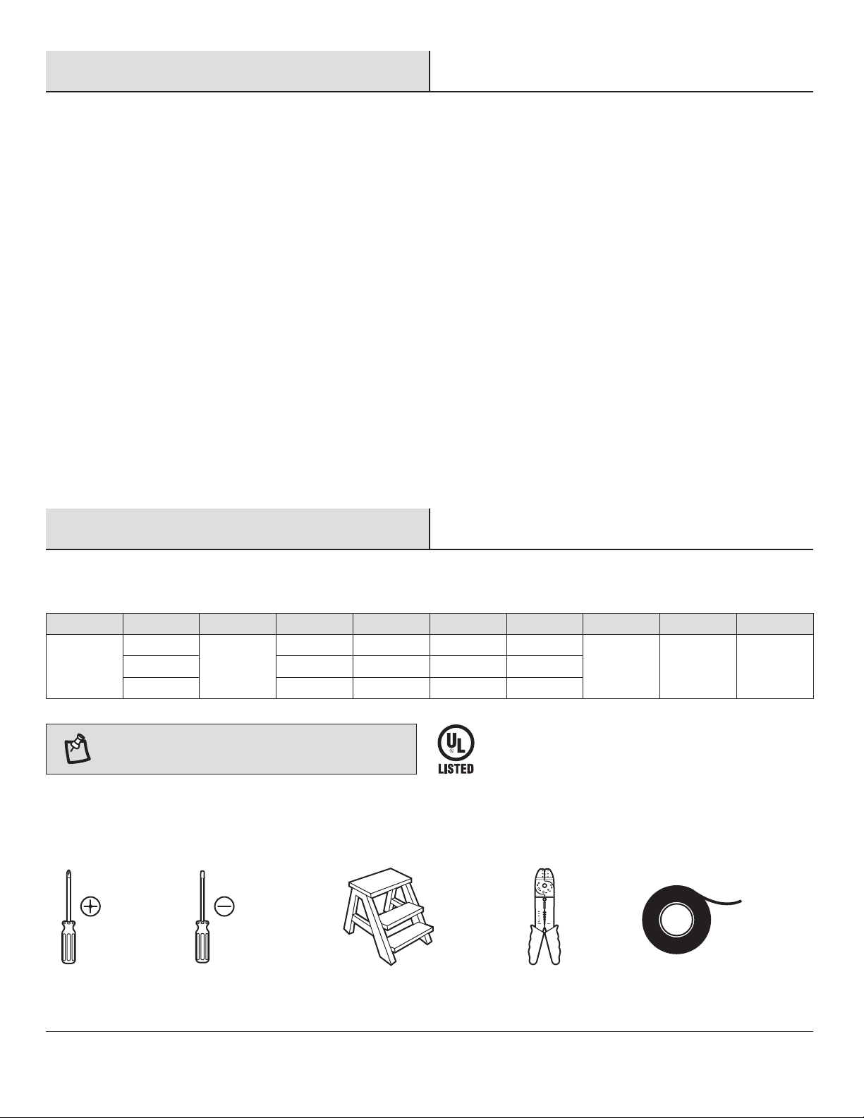
TOOLS REQUIRED
We warrant the fan motor to be free from defects in workmanship and material present at time of shipment from the factory for a period
of lifetime after the date of purchase by the original purchaser. We also warrant that all other fan parts, excluding any glass or acrylic
blades, to be free from defects in workmanship and material at the time of shipment from the factory for a period of one year after the
date of purchase by the original purchaser. We agree to correct such defects without charge or at our option replace with a comparable or
superior model if the product is returned. To obtain warranty service, you must present a copy of the receipt as proof of purchase. All
costs of removing and reinstalling the product are your responsibility. Damage to any part such as by accident, misuse, improper installation or by affixing any accessories, is not covered by this warranty. Because of varying climatic conditions this warranty does not cover
any changes in brass finish, including rusting, pitting, corroding, tarnishing or peeling. Brass finishes of this type give their longest useful
life when protected from varying weather conditions. A certain amount of “wobble” is normal and should not be considered a defect.
Servicing performed by unauthorized persons shall render the warranty invalid. There is no other express warranty. We hereby disclaim
any and all warranties, including but not limited to those of merchantability and fitness for a particular purpose to the extent permitted by
law. The duration of any implied warranty which cannot be disclaimed is limited to the time period as specified in the express warranty.
Some states do not allow limitation on how long an implied warranty lasts, so the above limitation may not apply to you. The retailer shall
not be liable for incidental, consequential, or special damages arising out of or in connection with product use or performance except as
may otherwise be accorded by law. Some states do not allow the exclusion of incidental or consequential damages, so the above
exclusion or limitation may not apply to you. This warranty gives specific legal rights, and you may also have other rights which vary from
state to state. This warranty supersedes all prior warranties. Shipping costs for any return of product as part of a claim on the warranty
must be paid by the customer.
Pre-Installation
SPECIFICATIONS
Fan Size
52 in
TOOLS REQUIRED
Speed
Low
Medium
High
NOTE: These are approximate measures. They do not
include amps and wattage used by the light kit.
PHILLIPS
SCREWDRIVER
Volts
120
Amps
0.22
0.38
0.54
FLAT BLADE
SCREWDRIVER
Watts
9.98
31.67
63.81
RPM
57
109
163
STEP
LADDER
CFM
1,519
2,973
4,329
N.W.
7.75 kg
(17.05 lbs.)
WIRE
STRIPPER
G.W.
8.70 kg
(19.14 lbs.)
C.F.
1.77 cu. ft.
ELECTRICAL
TAPE
4
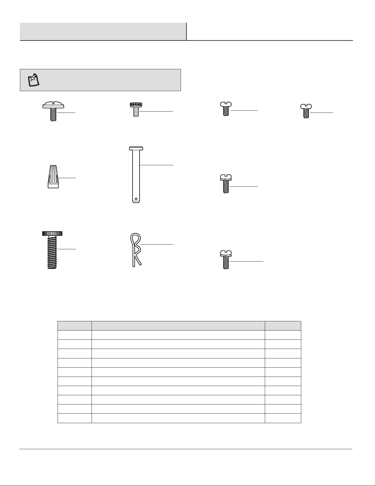
Pre-Installation (continued)
HARDWARE INCLUDED
Part
Description
Quantity
HARDWARE INCLUDED
NOTE: Hardware shown to actual size unless noted
otherwise in the table below.
AA
BB
CC
DD
EE
FF
GG
HH
JJ
II
Part
AA
BB
CC
DD
EE
FF
GG
HH
II
JJ
Description
Blade attachment screw and fiber washer
Plastic wire nut
Light holder thumbscrew (preassembled)
Canopy mounting screw with lock washer (preassembled)
Clevis pin (preassembled)
Cotter pin (preassembled)
Collar set screw (preassembled)
Collar mounting screw with lock washer (preassembled)
Blade arm screw with lock washer (preassembled)
Light kit mounting screw (preassembled)
5
Quantity
16
3
10
4
1
1
2
6
10
3
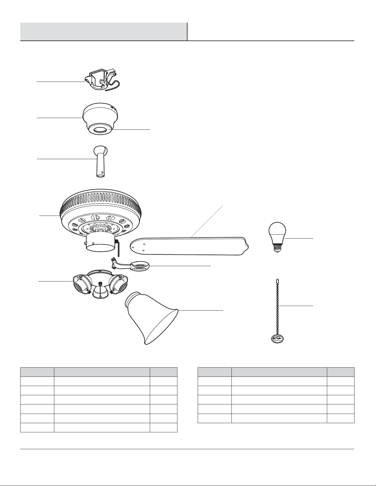
PACKAGE CONTENTS
Pre-Installation (continued)
PACKAGE CONTENTS
A
B
C
D
F
E
H
Part
A
B
C
D
E
F
Description
Mounting bracket (preassembled)
Canopy
Canopy bottom cover
Hanger ball/downrod assembly
Fan motor assembly
Blade
Quantity
1
1
1
1
1
5
G
Part
G
H
I
J
K
I
Description
Blade arm
Light kit
Glass shade
9.5-watt LED bulb
Pull chain and fob
J
K
Quantity
5
1
3
3
2
6
 Loading...