

Page 1
- 1 -
MBD-8F
Automatic Antenna Switch Controller
MBD-8F is an intelligent controller compatible with all eight-antenna switches manufactured by
Hamplus. It has a band decoder to receive the information coming from the connected radio equipment. In
addition to antenna switching, the MBD-8F also offers five frequency-driven GPOs ( General Purpouse Output),
one Band Data BCD Output, one output to command Band Pass Filter, 12 GPOs to automate the operation with
TopBeam's Waller Flag receiving antenna. The MBD-8F also commands the RS-24 and RS-44 Rotator switches.
There are four ways that antennas and enabled rotators can be selected; 1) manually by the front panel of the
MBD-8F, 2) manually by frequency or band change on the front panel of the transceiver, 3) automatically by
frequency or band change by the remotely controlled transceiver, or 4) automatically by a remotely controlled
personal computer via RS-232 serial port to the MBD-8F.
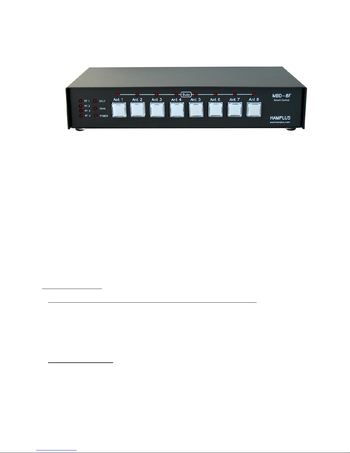
On the front panel is a set of eight illuminated push buttons for manual selection of antennas, eight “Busy” LEDs
to indicate which antennas are in use by other MBD-8F Controllers, four LEDs to indicate rotator selection, one
LED to indicate when the radio is transmitting, one LED to indicate the controller is in "Split Antenna" mode and
one LED to indicate when the MBD-8F is connected to +13.8 Vdc power.
Functions and operation
1- Startup (after all cable connections are made to switches, controllers and transceivers)
Powering the MBD-8F will energize the antenna switch relay for the previously, manually selected antenna. Or,
when connected to a transceiver, the controller will check the frequency or band the transceiver has selected
and will immediately trigger and light the push button switch of the last antenna selected at that frequency or
on that band. If connected, the rotator switcher, or other external equipment that is programmed using the GPO
outputs, the MBD-8F will select the last used devices.
2- Activation of the antennas
To choose any antenna, just press the corresponding push button. When the push button is pressed, it changes
the state of the antenna switch control line that activates the corresponding antenna relay on the AS-81, AS-82F,
AS-84F or AS-86F Antenna Switch. It also activates the selected rotator for that antenna through one of the
Rotator Switches, model RS-24 or RS-28, if used. Antenna and rotator switching are reported on the Busy Net
network so the other MBD-8F busy and rotator red LEDs signal, not allowing any other MBD-8F to switch to any
antenna and rotator already in use. Any conflict is signaled on the front panel of the MBD-8F by blinking the
Page 2

- 2 -
push button LED for two seconds, and the rotator LED with short and continuous flashes every second. The
rotator signal remains as long as there is a conflict.
3- Split Antenna Mode
This mode allows operation with two different antennas. One for transmission and one for reception.
Procedure to enter SPLIT mode:
A- First select the transmission antenna.
B- Then press and hold the PTT of the radio and press the desired antenna push button for reception for
two seconds. The push button will blink to confirm that the setting has been made. Then release the
push button and the PTT. From this point the Split LED on the panel will be lit indicating that it is
working with two antenas.
Immediately after programming the Split mode, perform the function test by pressing and releasing the
PTT of the radio and observing the push buttons of the MBD-8F that should alternate between the
chosen antennas.
To exit Split mode simply change the radio band or press the transmit antenna push
button.
4- Permanent Split Mode
Permanent Split is used with antenna(s) connected to the switch that are exclusively for reception. When we
select an antenna configured for permanent Split on the keyboard of the MBD-8F the Split mode is automatically
activated. This way we guarantee the use of the receiving antenna only in reception. This procedure must be
duplicated on all controllers connected to the same antenna switch that has receive only antenna(s) connected.
Procedure to configure Permanent Split mode:
A- First choose a transmission antenna.
B- Then press and hold the PTT of the radio and press the desired antenna push button for reception for a little
more than ten seconds. Notice the flashing of the push buttons that will confirm the acceptance of the
programming.
C- To undo this setting, first make sure that the Split LED is not lit. Then, while holding down the PTT, press the
desired push button for ten seconds. It is the same process used when programming was done.
5- GPOs with frequency drive ( GPO = General Purpouse Output )
These GPOs are used to trigger the tuning box of shortened antennas that use "high Q" coils. The trigger points
of the GPOs depend on the operating frequency. These points are defined by the user through the keyboard of
the MBD-8F. This procedure is only possible when the radio is connected to the MBD-8F in the CI-V (Icom) or RS232 mode for other manufacturers.
Procedure to configure the GPOs:
Press the chosen antenna push button for 5 seconds to enter Setup mode. In the configuration mode, the
antenna push button flashes eight times. Push buttons 5, 6 and 7 correspond to GPOs 1, 2 and 3 respectively.
Initially these three push button will be erased. Start with the lowest frequency within the band. Use the Radio
VFO and find the frequency for triggering the first GPO (GPO1). Once the desired frequency is found press push
button 5. The GPO1 will be highlighted and the 5 push button will be highlighted. Increase the frequency by
turning the VFO to the next desired point and press the push button 6 which will mark the second trigger point
(GPO2). Repeat the operation to find the third trigger point (GPO3) and press the push button 7. Perform a quick
test, turn the VFO of the radio through all frequencies of the band and check that the marking push buttons light
up at the frequencies that you have marked. In each segment of frequency only one push button will be
illuminated. Once the selection has been completed, it must be saved and returned to the normal operating
mode. To SAVE, simply press push button 8.
Page 3

- 3 -
6- Rotator Switch
The MBD-8F can also command a Hamplus model RS-24, or RS-44 rotator switch. With this equipment it is
possible to use one, two, three or four rotator controllers to read and control up to 4 rotators. The RS-24 is
suitable for stations with up to two transceivers and RS-44 for stations with up to four transceivers.
Procedure to configure the Rotators
Enter setup mode by pressing the antenna push button you wish to associate with a particular rotator for 5
seconds. This will cause the MBD-8F to enter configuration mode. Then, while in this mode, press the 1, 2, 3 or 4
push button to choose the rotator of this antenna. Once configured, the rotator indicator LED is lit. To exit the
configuration mode and SAVE, press push button 8. From this moment on, whenever the antenna associated to
the rotator is used, the rotator indicator LED in use (RT1, RT2, etc.) will light up and the respective rotator will be
connected to the control Used in this MBD-8F.
7- Communication with Icom, Yaesu, Kenwood, Elecraft K-3 via RS-232 and BCD
To use the MBD-8F's automation functions, it must communicate with the radio. For ICOM brand radios, we use
the CI-V protocol (MBD-8F CI-V port). With this protocol all the features described above will be able to work.
For the equipment of the YAESU brand we use the band data information, which allows all configurations except
the activation of the GPOs by frequency. For those of the brand Kenwood and Elecraft K3 the protocol used is by
the RS-232 communication port that allows use of all functions of the MBD-8F.
Elecraft K3 also has band-data information like the Yaesu.
CI-V Baud Rate 19200 ( Icom Radios ) RS-232 Baud Rate 9600 (Kenwood and K3)
8- Band Data Table
BCD Band Data
Band Frequency BCD
160 m 0.0 to 2.9 MHz 0001
80 m 3.0 to 4.8 MHz 0010
60 m 4.9 to 5.9 MHz 0000
40 m 6.0 to 8.9 MHz 0011
30 m 9.0 to 12.9MHZ 0100
20 m 13.0 to 16.9 MHz 0101
17 m 17.0 to 18.9 MHz 0110
15 m 19.0 to 22.9 MHz 0111
12 m 23.0 to 25.9MHz 1000
10 m 26.0 to 34.9 MHz 1001
6 m 35.0 to 54.9 MHz 1010
Frequency Band for communication via RS-232 and CI-V
Band 1 from 0 to 400 KHz, Band 2 from 400KHz to 550KHz, Band 3 from 550 KHz to 1.7 MHz, Band 4 from 1.7 to
3.0 MHz, Band 5 from 3.0 to 5.0 MHz, Band 6 from 5.0 to 6.0 MHZ, Band 7 From 6.0 to 8.5 MHz, Band 8 from 8.5
to 12 MHz, Band 9 from 12 to 16 MHz, Band 10 from 16 to 18.5 MHz, Band 11 from 18.5 to 23 MHz, Band 12
from 23 to 27 MHz, Band 13 from 27 MHz to 34 MHz MHz, Band 14 from 34 to 55 MHz,Band 15 above 55 MHz.
9- Antenna memory per band
The MBD-8F has a non-volatile memory for each of the eight antennas so that whenever an antenna is selected
this memory registers the band selected by the Radio. With each band change in the radio the MBD-8F will
activate the last antenna that was used in that band.
Note: The setting mode is only possible when the Radio is properly connected to the MBD-8F.
Page 4

- 4 -
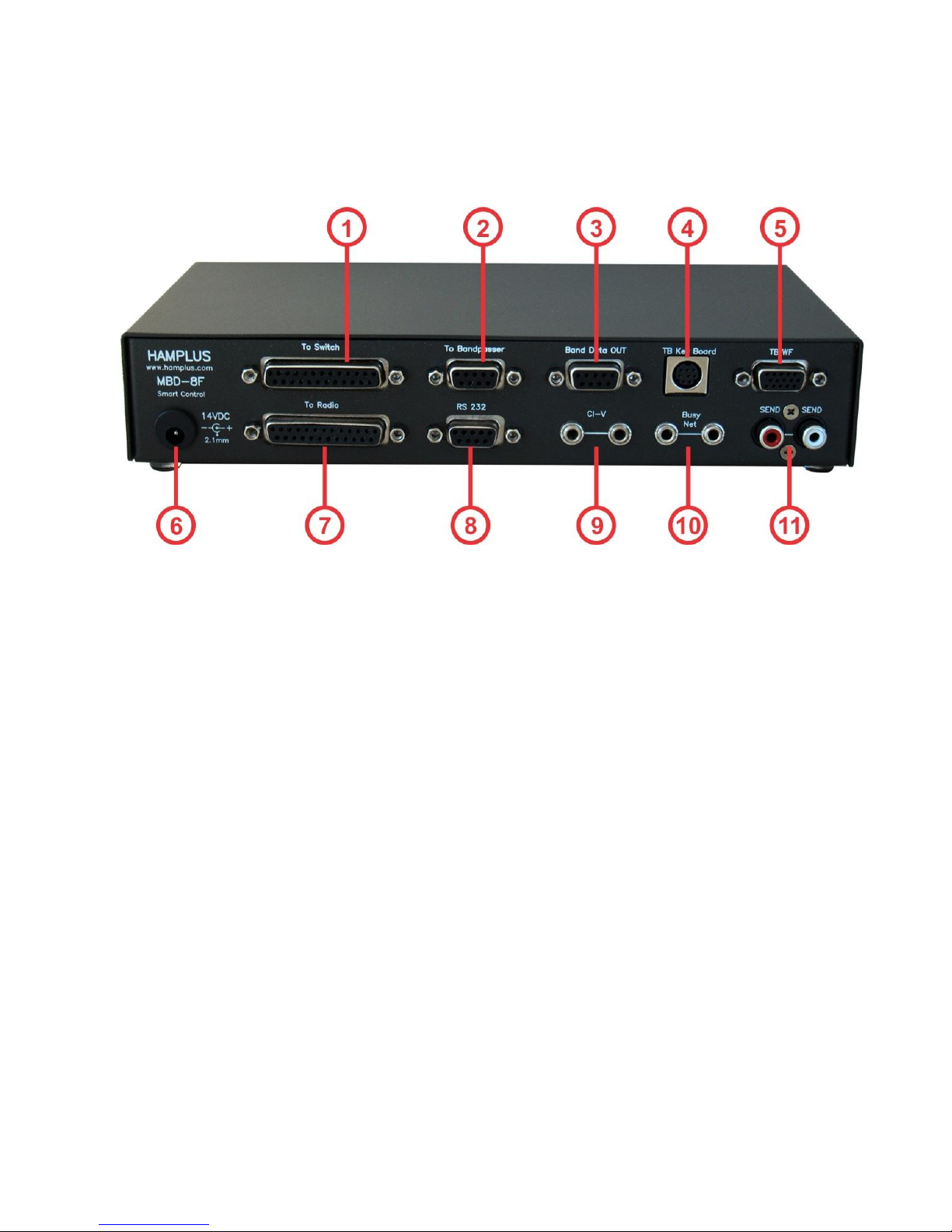
10- Connectors description (connector # on rear panel image)
a- Band Data Out (#3)
The DB-9 Band Data Out connector on the rear of the MBD-8F provides a Band Data output that
matches the frequency of the radio that is connected. When the MBD-8F receives the band information from
the Band Data, this same information will be passed to the Band Data Out connector. When receiving the
information through Frequency the conversion to Band Data will be done according to the table in item 8.
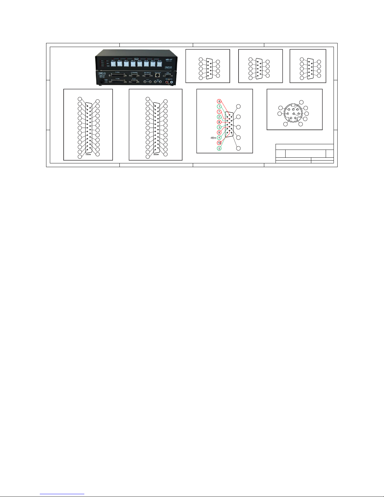
DB-9 Band Data Out connector
Pins Function
1 Band Data A
2 Band Data B
3 Band Data C
4 Band Data D
5 + 13.8 Vdc
6 Cmd 1
7 Cmd 2
8 GND
9 Cmd 3
b- Bandpasser Out (#2)
The DB-9 To Bandpasser connector on the rear of the MBD-8F sends + 13.8 Vdc for the Band Pass Filter
relays. They are outputs to 160m, 80m, 40m, 20m, 15m, 10m and one to Bypass. The Bypass output will be
triggered when the information received from the Frequency Radio or BCD is different from the information
available here for the Bandpasser Out.
DB-9 To Bandpasser connector
Pins Band Frequency Function
1 20 m 13.0 to 16.9 MHz On +13.8Vdc
2 40 m 6.0 to 8.9 MHz On +13.8Vdc
3 80 m 3.0 to 4.8 MHz On +13.8Vdc
4 160 m 0.0 to 2.9 MHz On +13.8Vdc
5 --------- ----------------------- GND
6 --------- -----------------------
7 --------- ----------------------- Bypass On +13.8Vdc
8 10 m 26.0 to 34.9 MHz On +13.8Vdc
9 15 m 19.0 to 22.9 MHz On +13.8Vdc
All control pins are Active High + 13.8 Vdc
c- TOPBEAM Waller Flag (#5)
The HD-15 connector labeled TB WF on the rear of the MBD-8F provides power (+ 13.8 Vdc) and the
controls for activating the filters of the Waller Flag receiving antenna control box. The commands follow the
Band data table or the Radio frequency.
HD-15 TB WF connector
Pins Band Frequency Data Function
1 160 m 0.0 to 2.9 MHz 0001 On Active Low
2 80 m CW 3.4 to 3.59MHz 0010 On Active Low
3 80 m SSB 3.6 to 4.8 MHZ 0010 On Active Low
Page 5

- 5 -
4 40 m 6.0 to 8.9 MHz 0011 On Active Low
5 30 m 9.0 to 12.9MHz 0100 On Active Low
6 and 7 -------- ------------------- ------ + 13.8vVdc
8 -------- ------------------- ------ PTT
9 and 10 -------- ------------------- ------ GND
11 -------- ------------------- ------ RTX On Active Low
12 -------- ------------------- ------ RX1 On Active Low
13 -------- ------------------- ------ RX2 On Active Low
14 -------- ------------------- ------ RX3 On Active Low
15 -------- ------------------- ------ RX4 On Active Low
d- DB-25 To Radio Connector (#7)
This connector receives power from the Radio (+ 13.8 Vdc), the transmit command (PTT) and the data
for frequency reading via RS-232 and Band reading via Band Data BCD.
DB-25 To Radio Connector
Pins Function Pins Function Pins Function
1 GND 10 NC 19 GND
2 BCD D 11 NC 20 GND
3 BCD B 12 NC 21 + 13.8 Vdc IN
4 GND 13 NC 22 NC
5 NC 14 GND 23 NC
6 GND 15 BCD C 24 NC
7 GND 16 BCD A 25 NC
8 + 13.8 Vdc IN 17 GND
9 PTT In 18 GND
e- DB-25 To Switch Connector (#1)
DB-25 connector on the rear of the MBD-8F provides the commands for driving eight Antennas, four
Rotators and four special GPOs driven by frequency or Band
DB-25 To Switch Connector
Pins Function Pins Function Pins Function
1 Ant 1 10 GND 18 Rotator 1
2 Ant 2 11 GPO1 19 Rotator 2
3 Ant 3 12 GPO3 20 Rotator 3
4 Ant 4 13 Expansion 21 Rotator 4
5 Ant 5 14 Rotator 1 22 Cmd 80m
6 Ant 6 15 Rotator 2 23 Cmd 40m
7 Ant 7 16 Rotator 3 24 GPO 2
8 Ant 8 17 Rotator 4 25 GND
9 + 12v
f- DB-9 RS-232 connector (#8)
The DB-9 connector identified as RS-232 on the back of the MBD-8F provides connection to
computers and with Elecraft and Kenwood radios.
DB-9 RS-232 connector
Pins Function
1 NC
2 RX
3 TX
4 NC
5 GND
6 NC
7 NC
Page 6
- 6 -
8 NC
9 NC
1- To Switch Output Commands to Antenna Switch and Rotator Switch
2- To Bandpasser Output Commands for Bandpass Filter
3- Band Data Out Band Data Output (BCD)
4- TB Key Board Output for Key Board Antenna TopBeam Receiver Waller Flag
5- TB WF Connects to the PFIU of the receiving antenna TopBeam Waller Flag
6- AUX. Power Supply Auxiliary Power Input (13.8 Vdc)
7- To Radio Input Power, Band Data and PTT Radio
8- RS-232 Communication with Kenwood, Elecraft K3 to PC COM port
9- CI-V Communication with Icom radios via CI-V port
10- Busy Net Busy Network for indication of antennas in use
11- Send Auxiliary input and pass-through output for PTT (Send)
Page 7
- 7 -
1 / 1
Connector Pin Identification
PI-MBD8F
03 / 17 / 2017
A4
Rev.
Number:Size:
Date:
Filename: Page.
MBD-8F CONNECTOR PIN IDENTIFICATION
1.0
By: Valmor
HAMPLUS
MBD-8F
MBD-8F
8
9
7
6
1
2
3
4
5
DB9M
20m
40m
80m
160m
Gnd
Aux
Bypass
10m
15m
To Bandpasser
8
9
7
6
1
2
3
4
5
DB9M
RX
TX
Gnd
RS 232
3
4
6
12
8
5
7
RTX 1
RX 3
RX 2
+12VDC
Gnd
RX 1
RX 4
Gnd
TB Key Board
11
12
13
14
15
+12VDC
160m
+12VDC
Send (PTT)
80cw
80 ssb
Gnd
Gnd
30m
RTX
RX 1
RX 2
RX 3
RX 4
DB15M
VGA
TB WF
8
9
7
6
1
2
3
4
5
DB9M
B.Data A
B.Data B
B.Data C
B.Data D
Gnd
Band Data OUT
+12VDC
Cmd 1
Cmd 2
Cmd 3
16
17
15
18
19
20
21
22
23
24
25
14
1
2
3
4
5
6
7
8
9
10
11
12
13
Gnd
Bcd A
Bcd C
Gnd
Gnd
Gnd
+12VDC
Send (PTT)
Gnd
Bcd B
Bcd D
Gnd
Gnd
Gnd
+12VDC
To Radio
16
17
15
18
19
20
21
22
23
24
25
14
1
2
3
4
5
6
7
8
9
10
11
12
13
Ant 1
Ant 2
Ant 3
Ant 4
Ant 5
Ant 6
Ant 7
Ant 8
+12VDC
Gnd
Rot 1
Rot 2
Rot 3
Rot 4
Rot 1
Rot 2
Rot 3
Rot 4
Cmd 80m
Cmd 40m
Expansion
To Switch
Cmd 1
Cmd 3
Gnd
Cmd 2
 Loading...