

Page 1
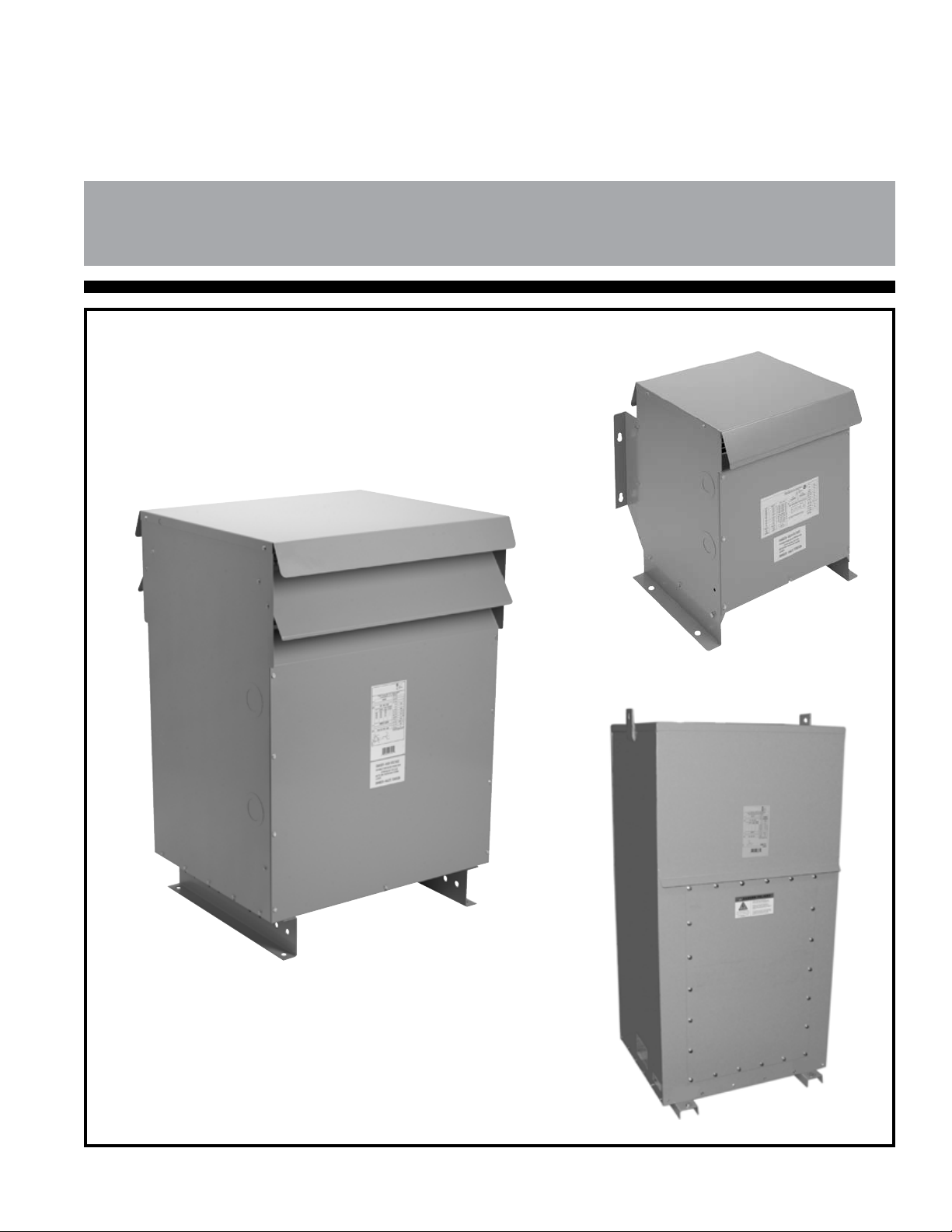
INSTALLATION, OPERATION AND MAINTENANCE GUIDE
FOR INDOOR/OUTDOOR DRY-TYPE TRANSFORMERS
FOR INDOOR/OUTDOOR DRY-TYPE TRANSFORMERS
WHICH UTILIZE A NH SERIES, NJ1, NJ2, NJ3 OR NJ4 ENCLOSURE
WHICH UTILIZE A NH SERIES, NJ1, NJ2, NJ3 OR NJ4 ENCLOSURE
*Note: This guide is Trilingual
(English, French and Spanish)*
Literature No.: IOMGDDI
Issue Date: May 2010
Page 2

Safety Precautions
(1) Do not lift or move a transformer without proper equipment and experienced personnel. On
some larger kVA distribution transformers, lifting provisions are provided on the inside of the
enclosure on the core & coil.
(2) Do not off-load the transformer until a full inspection has been completed.
(3) Use terminals only for electrical connections. Flexible connectors are recommended for bus
connections. The transformer terminals are not designed to support the weight of supply or load
cables. Uni-strut supports can be added in the eld providing proper clearances are maintained.
(4) Connections should only be in accordance with the nameplate diagram or connection drawings.
(5) Make sure all power is disconnected before attempting any work on a transformer or inside of
control box and ground all windings.
(6) Make certain all ground connections, line terminals and selected taps are complete and tighened
before energizing the transformer.
(7) Do not attempt to change any taps - primary or secondary, while the transformer is energized.
(8) Do not change connections when the transformer is energized.
(9) Do not tamper with control panels, alarms, interlocks or control circuits.
(10) Do not adjust or remove any accessories or cover plates while the transformer is energized.
No supply cables should come in contact with the core or any live part except the terminal that it
is intende for.
CONTENTS
General 3
Handling 3
Receiving & Inspection 3
Storage 3
Installation 3
Ventilation 4
Accessibility 4
Transformer Sound Levels 4
Cable Connections 4
Grounding 5
Inspection Before Energization 5
Operation 5
Maintenance 6
Dry-out of Transformers 6
Accessories 6
Appendix A 7
Appendix B 8
Figure 1 9
Figure 2 10
Figure 3 11
Notes 12
- 2 -
Page 3

INSTALLATION, OPERATION AND MAINTENANCE
OF DRY-TYPE TRANSFORMERS
GENERAL
Dry-type transformers are manufactured to
provide optimum performance for a lifetime of
uninterrupted service. Careful attention to the following
instructions is recommended for safe and reliable
operation.
Installation, operation and maintenance of
transformers should be performed by authorized
persons, familiar with electrical apparatus and the
potential hazards involved.
Warning: Danger! There is the potential of
electric shock whenever working in or
around electrical equipment such as
transformers. Power must be shut off
before any work is conducted on a
transformer.
As with any electrical device, transformers must
be installed according to the requirements of the
national and local electrical codes. Refer to ANSI/IEEE
C57-94 may also be referred to for recommended
installation, application, operation and maintenance of
dry-type transformers.
HANDLING
Transformers are palletized and can either be
lifted via a forklift truck or hoisted by the lifting lugs
provided.
Appropriate lifting equipment should be used
relative to the size of each transformer. For safety
purposes and to protect the transformer, spreader bars
are recommended.
No attempt should be made to lift or move a
transformer from any points on the unit other than
those indicated. Refer to Figures 1 and 2 (pages 9 and
10).
RECEIVING & INSPECTION
Immediately after receiving the transformer, it
should be inspected for any transit damage and for
correctness against the shipping documents.
The unit should be examined for any breaks in its
packaging, dented or damaged enclosures or missing
parts from the packing list.
If any damage is noted, a claim should be led
immediately with the carrier and a second copy of all
pertinent information relative to the order and the
circumstances should be led with the local sales
ofce.
If this examination of the unit takes place
outdoors, caution should be exercised such that
inclement weather would not present further hazard.
STORAGE
Transformers that will not be immediately
installed and energized, should be stored in a clean
dry environment away from any environmental
airborne contaminants.
It is recommended that transformers be stored in
a heated building with the protective plastic wrap still
installed.
INSTALLATION
Enclosures are designed and approved
in accordance with specications
CSA 22.2 No. 47 (General Purpose),
CSA 22.2 No. 94 (Specialty Enclosures),
NEMA 250 and UL 50.
For IEC enclosure equivalents please see
IEC 60529 (Enclosure Classications
Designations).
a) Indoor/Outdoor Dry-Type Transformers with
Enclosures
Most dry-type transformers are supplied with
either a type 3R, 4 or 12 enclosure. Units may be
installed indoors, or outdoors where applicable. If
equipped with a type 1 enclosures, these units are for
indoor use only.
Ventilated enclosures are recommended for
indoor installation but may also be installed outdoors
where weather conditions allow a type 3R ventilated
enclosure to be installed.
For any outdoor location, the appropriate
applicable codes must be followed including cable
installation and hardware suitable for outdoor service.
Water tight couplings must be used at the
knockouts and any holes in the enclosure must be
drilled below any un-insulated live parts, (below LV
terminals).
Dry-type transformers may be located in an
upright position on walls, oors, posts, beams or other
- 3 -
Page 4

locations capable of supporting their weight with the
proper accessories attached. Refer to Appendix B
(page 8) for wall mounting kits.
Conventional open ventilated dry-type
transformers have a bottom screen for air convection.
When transformers are mounted above the ground
surface a catcher plate should be installed under each
transformer as a safety precaution against any hot
particles that may fall through the screen in the event
of a faulted condition. Refer to Appendix B (page 8).
It is important that ventilated transformers be
installed in a dry area where the ambient air is clean
and free of dust, dirt, corrosive fumes, moisture, heat
or other adverse conditions. Transformers should not
be installed in such a place having the possibility of
water logging inside the enclosure.
In the event that a transformer has been
subjected to moisture or dampness before installation,
ensure that it is completely cleaned and dried before
energization. The blowing of warmed air through the
transformer is recommended to dry internal
components. Refer to the section on dry-out of
transformers.
b) Indoor/Outdoor Transformers with Non-
Ventilated Type 4, 4X or 12 Enclosures.
However, transformers should not be located in
areas where stored items are likely to interfere with
either natural air convection or the capability to have
them inspected. Passage ways or other areas where
people could be exposed to live parts during
inspection should also be avoided.
Adequate protection should be provided under
any circumstances.
TRANSFORMER SOUND LEVELS
Transformers are an electrically energized
apparatus and by their nature emit sound due to their
component materials.
Transformers are required to meet NEMA
standards for the maximum sound levels permissible.
These sound level standards vary from 40 to 60 DB
and hence, can be an annoyance if located in close
proximity to where people work or reside.
Care should therefore be exercised in selecting
sites for transformers particularly to avoid sensitive
areas like hospitals, classrooms, medical or ofce
facilities.
The following guidelines may be helpful:
Transformers equipped with non-ventilated type
4, 4X or 12 enclosures maybe located either indoors or
outdoors in any similar location noted above. Nonventilated enclosed transformers, although slightly
larger, offer much greater protection against a variety
of elements such as dust, dirt, snow, moisture, rain
etc.
For any outdoor location, the appropriate
applicable codes must be followed including cable
installation and hardware suitable for outdoor service.
VENTILATION
Transformers are required to be installed in an
area where they can be cooled by means of the free
circulation of air where the average ambient
temperature is 30°C (86°F) and should not exceed
40°C (104°F) at any time.
Adequate ventilation is essential for transformers
to meet their nameplate kVA capability. All general
purpose transformers should be located away from
walls or any other obstructions (at least 6 inches when
oor mounted and 4 inches when wall mounted) to
allow free, clean circulation of air through the
ventilation openings or around a non-ventilated unit.
ACCESSIBILITY
NEC standards require that transformers be
accessible for inspection and located accordingly.
Units should be mounted away from corners or
reecting walls or ceilings.
Cable or other exible conduit should be
considered to make connections.
All dry-type transformers are provided with
isolation rubber mounts between the core and
coil assembly and the enclosure. However,
sound absorbing vibration isolators may also be
installed between the transformer and its
mounting surface.
Acoustically absorbing materials could be
considered for walls and ceilings around the
unit.
The location of the unit should be located as
far as practical from areas where sound levels
could be considered undesirable.
CABLE CONNECTIONS
The connecting cable size is determined from the
line current rating of the transformers primary and
secondary windings and may be selected from the
information in Appendix A (page 7). Cables rated for at
least 90°C (194°F) is recommended as are ALC9CU
lugs.
Convenient pre-punched knockouts are provided
on all ventilated transformer enclosures up to 150 kVA
- 4 -
Page 5

three phase and 100 kVA single phase, to facilitate
cable entry.
For non-ventilated transformers, pre-punched
knockouts are not provided and the appropriate cable
connector suitable for the application must be used.
Please refer to gures 1 and 2 (pages 9 and 10)
for cable entry locations.
Warning: Never attempt to change connections or taps unless the transformer is
de-energized and all windings grounded.
Side entry of cables is recommended as it leaves
the ventilated areas unobstructed.
Cable connection lugs of plated copper or
aluminum may be used to connect to the transformer
terminals. Terminals should be cleaned and electrical
joint compounds are recommended for use on all
electrical connections.
Refer to the transformer nameplate for primary
and secondary voltage connection combinations and
primary and/or secondary tap positions as applicable.
Transformers received from the factory will have
tap leads installed on the nominal, or 100%, voltage
position. The balance of the tap positions will still be
coated with impregnation material and insulation.
To change taps, it is necessary to remove this
insulation by gently removing the protective coating
from the surface appropriately. The surface of the tap
lead should be clean and coated subsequently with
electrical compound.
NOTE: After installation of cables and
connectors, a minimum of 1” clearance
must be maintained from energized parts
to all case parts.
GROUNDING
secondary and primary to secondary, should be
greater than 10k ohms.
b) Before energizing and connecting any loads,
please measure and verify the output voltage
matches nameplate specications.
c) Ensure correct phase connections. Refer to the
nameplate vector diagram.
d) The load on a delta secondary winding with a 120
volt center tap should not exceed the normal
current rating of the winding. This center tap is
designed for a max. of 5% of the nameplate kVA.
e) When windings are connected in parallel (as in
the case of dual voltage primaries), the primary
taps for all coils must be connected to the
identical percentage tap positions to avoid the
shorting of turns. For tap positions, refer to the
nameplate on the transformer.
f) The enclosure should be grounded with the
appropriately sized conductor.
g) The total load among all the phases should be
balanced as much as possible for optimum
performance of the transformers windings.
Any three phase or single phase load may be
connected to the transformer but the kVA loading
on each phase must not exceed 1/3 of the
nameplate kVA rating.
h) The clearance and tightness of all electrical
connections should be checked.
i) If there is any reason to suspect that the
transformer has been exposed to moisture during
transit or storage, it should be checked for
dryness before energization. This can be done by
making an insulation resistance test. Dry-out
procedures are on page 6.
All core and coil assemblies are solidly grounded
to the enclosure internally to ensure that all conductive
metal parts have the same potential.
The transformer enclosure in turn should also be
securely and effectively grounded as a safety
precaution.
This grounding should be in accordance with
national electrical code standards.
INSPECTION BEFORE ENERGIZATION
For the safe and proper operation of the
transformer, please check and verify the following:
a) The insulation resistance, core to primary, core to
OPERATION
For all relatively normal and clean installations,
dry-type transformers will operate satisfactorily under
normal conditions of energization and load.
For your reference, fully loaded dry-type
transformers may appear warm to the touch,
particularly on the cover of the unit.
Standards permit the temperatures of the cover
to be 65°C (149°F) over ambient. This represents
normal loading and should not be of concern.
Dry-type transformers are designed to operate
continuously at their full nameplate kVA rating.
ANSI C57.96 provides guidance for loading
- 5 -
Page 6

transformers under different conditions including:
Ambient temperatures that are varied from the
ambient temperatures required for transformer
operation.
Short time overload as it relates to time and
temperature and the corresponding loss of life of
the transformer.
Overload that results in a reduction of life
expectancy of the transformer.
If the transformer is experiencing increased
temperatures, the following load characteristics
should be considered immediately:
Rigorous motor starting loads or other impact
type loading for which a specic transformer for
that application is required.
Over-excitation of unit due to excess supply line
voltage or current.
Maintenance would include internal cleaning,
tightening of links and bolted connections, servicing
and inspection of auxiliary devices.
Air ducts should be free of any accumulation of
dust and debris and any bolted connections of
terminals must be in good condition.
Vacuuming or blowing of compressed air from
the top down is an accepted practice for removing dust
from the ducts of a transformer coil. Low pressure, dry
air should be used to avoid further contamination of
the windings by foreign material.
The ground connection should also be checked
to ensure a low impedance connection. The
accumulation of ice, snow or any other object blocking
the ventilation should be cleaned up immediately
during the operation of the transformer.
On outdoor units where filters have been
installed, being exposed to the outside atmosphere
can cause the filters to get dirty quickly. A periodic
check of the filters will help avoid filter clogging and
thus transformer overheating. Also, never run the
transformer without the filters properly in place.
Ambient temperatures above standard.
Overload beyond ANSI C57.96 guidelines.
Harmonic distortions of the supply line voltage
and currents.
If overheating is noted, any attempt to add
supplemental fan cooling must be in accordance with
factory installation guidelines. Incorrectly installed fans
can misdirect the airow and cause serious
deterioration of the insulation life in a transformer coil.
Dry-type transformers can be shut down and
stored for extended periods of time without any
deterioration. Care must be exercised to clean and dry
units prior to energization, as previously outlined.
MAINTENANCE
Under normal operating conditions and
environments, dry-type transformers do not require
maintenance. However, periodic care and inspection is
a good practice particularly dependent on the
environmental conditions in which the unit is installed.
Peripheral inspection and external dust removal
may be carried out while the transformer is in
operation. However, access covers must not be
opened under energized conditions.
Internal maintenance must be performed
with a transformer de-energized, isolated
and with the terminals grounded.
DRY-OUT OF TRANSFORMERS
In the event that transformers have been
exposed to moisture such as condensation or rain, it is
advisable to dry-out any unit prior to energization.
Drying may be accomplished by using any hot or
warmed air, radiant heat or internal heat that is
directed through the windings. Heated air should be
allowed to rise up through the windings for a minimum
of twenty four (24) hours after the evidence of
condensation is no longer visible.
Transformers that have been exposed to ood
conditions, direct rain or sprinklers, may not be able to
be dried out appropriately. Contact the transformer
manufacturer for appropriate action.
ACCESSORIES
Dry-type distribution transformers are available
with a number of accessories to facilitate installation.
Consult your local dealer or distributor for the
purchase of any of the items which may be carried in
inventory.
1) Wall Mounting Brackets
Encapsulated transformers have integral wall
mounting capabilities for units up to 285 lbs. Units over
285 lbs. must be oor mounted only.
Ventilated dry-type transformers are normally
designed to be oor mounted only. However, some
ventilated units up to 51kVA are supplied in enclosures
that have integral wall mounting capabilities. These
units can be conveniently mounted on walls, beams or
- 6 -
Page 7
poles.
Conventional open ventilated dry-type
transformers have a bottom screen for air convection.
When transformers are mounted above the ground
surface a catcher plate should be installed under each
transformer as a safety precaution against any hot
particles that may fall through the screen in the event
of a faulted condition. Refer to Appendix B (page 8).
2) Sound Isolation Pads
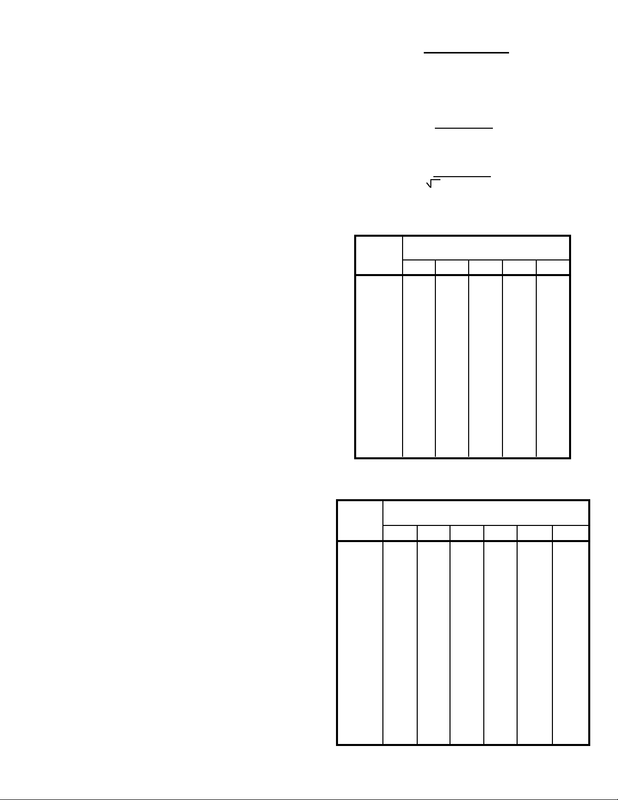
APPENDIX A
AMPACITY RATINGS FOR CONNECTIONS
A. For a single phase transformer
Line Amperes = volt-amperes
line volts
B. For a three phase transformer
All dry-type transformers have rubberized sound
absorbing pads mounted internally between the core
and coil assembly and the enclosure.
For maximum absorption of vibration and
emission of sound, additional sound isolation pads are
recommended for installation between the transformer
and the mounting surface.
These molded neoprene and steel plate
assemblies virtually eliminate vibration noise between
the transformer and the mounting surface.
Consult the manufacture’s catalog for the part
number of the correct isolation pad required
3) Connectors
Connectors for the installation of dry-type
transformers are readily available. These connectors
are suitable for either copper or aluminum cable.
Connectors should be sized and installed in
accordance with your local electrical code
requirements using the best practices to ensure safe
and reliable operation. Cable surfaces should be
cleaned and electrical compound should be used for
all joints.
Selecting Connectors
a) Determine the primary current for the required
transformer from the Appendix A.
b) Similarly, determine the secondary current rating
for the transformer from Appendix A.
c) For 120/240 voltage connections the current
should be based on 240 volts.
d) For 240/480 volt connections, the current should
be based on 480 volts.
Line Amperes = volt amperes
3 X line Volts
Full Load Current Table
Single Phase Transformer
Current in Amperes
kVA
Rating 120V 240V 416V 480V 600V
3 25.0 12.5 7.21 6.25 5.00
5 41.6 20.8 12.0 10.4 8.33
7.5 62.5 31.2 18.0 15.6 12.5
10 83.3 41.6 24.0 20.8 16.6
15 125 62.5 36.0 31.2 25.0
25 208 104 60.0 52.0 41.6
37.5 312 156 90.1 78.1 62.5
50 416 208 120 104 83.3
75 625 312 180 156 125
100 833 416 240 208 166
150 1250 625 360 312 250
167 1391 695 401 347 278
250 2083 1041 600 520 416
333 2775 1387 800 693 555
Full Load Current Table
Three Phase Transformer
Current in Amperes
kVA
Rating 208V 240V 380V 416V 480V 600V
2 5.55 4.81 3.03 2.77 2.40 1.92
3 8.32 7.21 4.55 4.16 3.60 2.88
6 16.6 14.4 9.11 8.32 7.21 5.77
9 24.9 21.6 13.6 12.4 10.8 8.66
15 41.6 36.0 22.7 20.8 18.0 14.4
30 83.2 72.1 45.5 41.6 36.0 28.8
45 124 108 68.3 62.4 54.1 43.3
75 208 180 113 104 90.2 72.1
112.5 312 270 170 156 135 108
150 416 360 227 208 180 144
225 624 541 341 312 270 216
300 832 721 455 416 360 288
450 1249 1082 683 624 541 433
500 1387 1202 759 693 601 481
600 1665 1443 911 832 721 577
750 2081 1804 1139 1040 902 721
- 7 -
Page 8
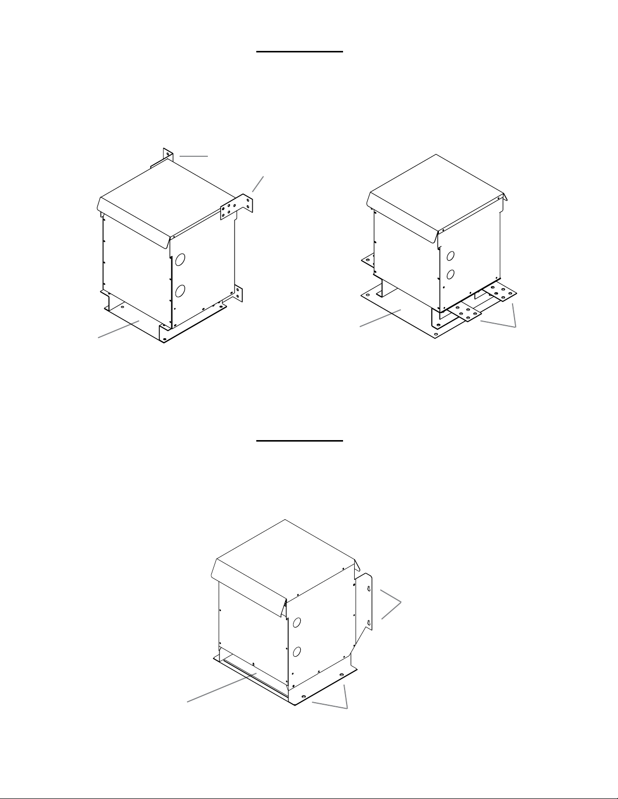
APPENDIX B
LOCATION OF WALL MOUNTING BRACKETS AND CATCHER PLATES
FOR NH3 SERIES TYPE 3R ENCLOSURES
Optional Wall
Mounting Bracket
Catcher Plate
Where Local Code Requires
Catcher Plate
Where Local Code Requires
APPENDIX B
LOCATION OF WALL MOUNTING BRACKETS AND CATCHER PLATES
FOR NH5 & NH6 SERIES TYPE 3R ENCLOSURES
Wall Mounting
Hole Locations
Optional Ceiling
Mounting Bracket
Catcher Plate
Where Local Code Requires
Floor/Ceiling Mounting
Hole Locations
- 8 -
Page 9
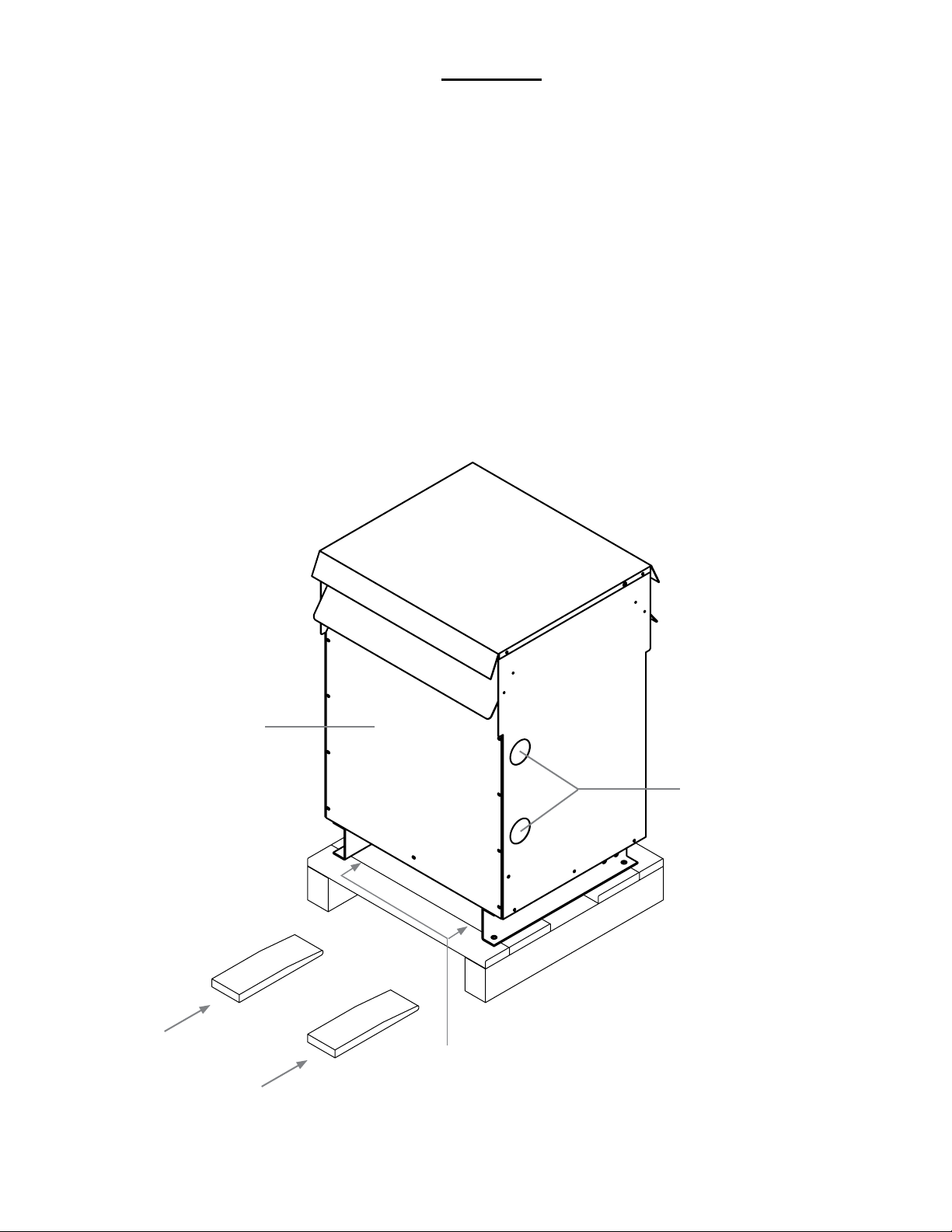
FIGURE 1
Typical Type 3R, NH Series Ventilated Enclosure Assembly for Three Phase and Single
Phase Transformers.
Notes:
Handling - units are designed to be raised by a fork lift from underneath the pallet. Final positioning of the unit 1.
with the pallet removed can be via a fork lift under the transformer with the forks between the channels.
Shipping - units are shipped on pallets which are to be removed at installation. 2.
Installation - This transformer can be installed indoor or outdoor providing a degree of protection against falling 3.
rain, sleet and external ice formation.
All general purpose/drive isolation transformers should be located away from walls or any other obstructions at 4.
least 6 inches when oor mounted and 4 inches when wall mounted.
DO NOT block bottom ventilation area.5.
Removable front
access panel
Position fork
lift under pallet
Cable entrance
knockouts (2 per side)
For nal positioning
with pallet removed,
fork lift points are under
the transformer
- 9 -
Page 10
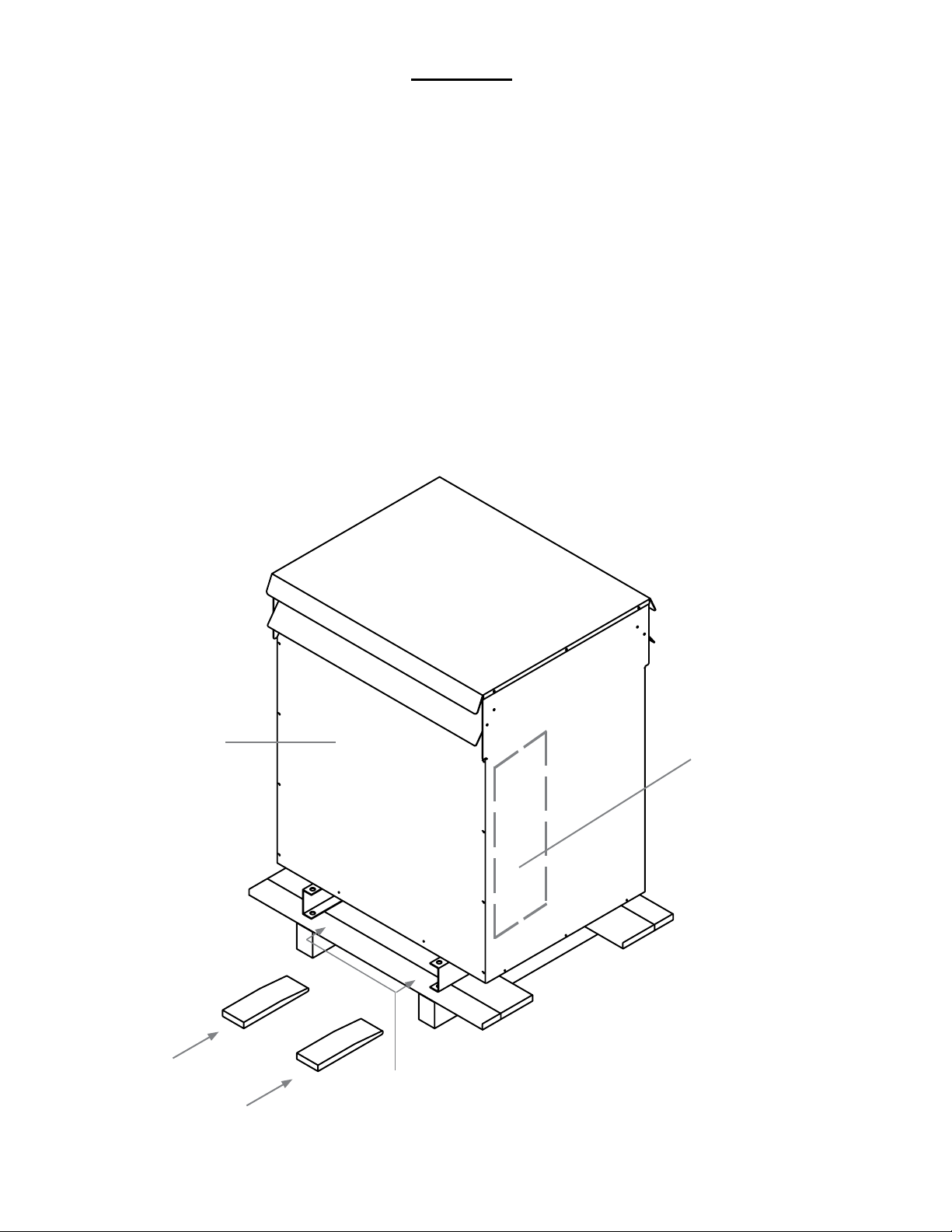
FIGURE 2
Typical Type 3R, NJ Series Ventilated Enclosure Assembly for Three Phase or Single Phase
Transformers.
Notes:
Handling - units are designed to be raised by a fork lift from underneath the pallet. Final positioning of the unit 1.
with the pallet removed can be via a fork lift under the transformer with the forks between the channels. (Note:
for transformers weighing greater than 2350 lbs should be lifted by removing the top panel and
accessing the lifting provisions on top of the top of the core and coil.)
Shipping - units are shipped on pallets which are to be removed at installation. 2.
Installation - This transformer can be installed indoor or outdoor providing a degree of protection against falling 3.
rain, sleet and external ice formation.
All general purpose/drive isolation transformers should be located away from walls or any other obstructions at 4.
least 6 inches when oor mounted and 4 inches when wall mounted. (Note: These enclosures are not intended
to be wall mounted. They may be mounted on a customer supplied platform.)
DO NOT block bottom ventilation area.5.
Removable front
access panel
Position fork
lift under pallet
Recommended cable
entry location (both
sides). Refer to
outline drawing for
exact dimensions.
For nal positioning with pallet
removed, fork lift points are
under the transformer. Forks
must be inserted all the way
through the depth.
- 10 -
Page 11
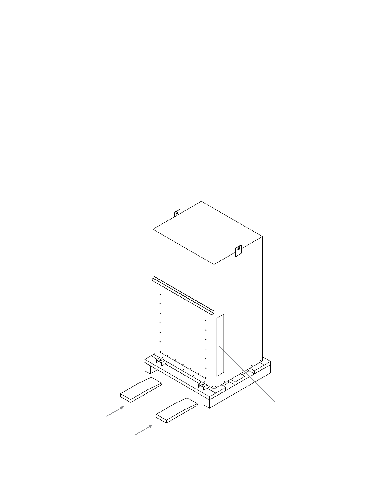
FIGURE 3
Typical Type 4 & 12, NH Series Non-Ventilated Enclosure Assembly for Three Phase or
Single Phase Transformers.
Notes:
Handling - units are designed to be raised by a fork lift from underneath the pallet. Final positioning of the unit 1.
with the pallet removed can be via a fork lift under the transformer with the forks between the channels.
Shipping - units are shipped on pallets which are to be removed at installation. 2.
Installation - This is a non-ventilated indoor or outdoor enclosure designed primarily to provide a degree of 3.
protection against falling dirt, rain, sleet, snow, windblown dust, splashing water, hose-directed water and that will
be undamaged by the external formation of ice on the enclosure. It is suitable in areas where exposure to large
amounts water from any direction is possible. (Note: not submersible)
All general purpose/drive isolation transformers should be located away from walls or any other obstructions at 4.
least 6 inches when oor mounted and 4 inches when wall mounted.
Lifting Hook
Removable front
access panel
Position fork
lift under pallet
Recommended cable entry location
(either side). Refer to outline
drawing for exact dimensions.
- 11 -
Page 12

Notes
Page 13

GUIDE D'INSTALLATION, DE FONCTIONNEMENT ET
D'ENTRETIEN
POUR LES TRANSFORMATEURS A SEC INTÉRIEUR/EXTÉRIEUR
POUR LES TRANSFORMATEURS À SEC INTÉRIEUR/EXTÉRIEUR
UTILISANT UN BOÎTIER DE LA SÉRIE NH, NJ1, NJ2, NJ3 OU NJ4
UTILISANT UN BOÎTIER DE LA SÉRIE NH, NJ1, NJ2, NJ3 OU NJ4
N° de document: IOMGDDI
Date de publication: Mai 2010
Page 14

Consignes de sécurité
(1) Ne levez pas et ne déplacez pas un transformateur sans disposer de l'équipement approprié et du personnel
expérimenté. Sur certaines unités de grandes dimensions, les dispositifs de levage sont situés à l'intérieur du
boîtier sur le noyau-bobines.
(2) Ne déchargez pas le transformateur tant qu'une inspection complète n'a pas été exécutée.
(3) N'utilisez les bornes que pour les branchements électriques. Il est recommandé d'utiliser des connecteurs
exibles pour les connexions sur barre. Les bornes du transformateur ne sont pas conçues pour supporter le
poids des câbles d'entrée ou de sortie. Des supports de type "Uni-Strut" peuvent être ajoutés au site en s'assurant de rencontrer les distances électriques.
(4) Les branchements doivent respecter le schéma de la plaque signalétique ou les diagrammes de connexion.
(5) Vériez que la source d'alimentation est coupée avant de commencer à travailler sur un transformateur ou à
l'intérieur de la boite de jomction Mettre tous les enroulements à la terre.
(6) Vériez que toutes les liaisons à la terre, les bornes d'entrée et de sortie et les prises sélectionnées sont com-
plètes et sont bien serrées avant de mettre le transformateur sous tension.
(7) Ne tentez pas de changer des prises (primaires ou secondaires), alors que le transformateur est sous tension.
(8) Ne changez pas les branchements lorsque le transformateur est sous excitation.
(9) N'altérez pas les panneaux de commande, les alarmes, les verrouillages ni les circuits de commande.
(10) Ne réglez pas et ne retirez pas les accessoires ou les plaques de recouvrement lorsque le transformateur est
sous tension. Les câbles d'entrée et de sortie ne doivent pas venir en contact avec le noyau ou toutes autres
parties vivantes sauf les bornes conçues à cette n.
TABLE DES MATIÈRES
Informations générales 15
Manutention 15
Contrôle et inspection 15
Entreposage 15
Installation 15
Ventilation 16
Accessibilité 16
Niveaux de bruit du transformateur 16
Branchement des câbles 16
Mise à la terre 17
Inspection avant la mise sous tension 17
Fonctionnement 17
Entretien 18
Séchage des transformateurs 18
Accessoires 18
Appendice A 19
Appendice B 20
Figure 1 21
Figure 2 22
Figure 3 23
Notes 24
- 14 -
Page 15

INSTALLATION, FONCTIONNEMENT ET ENTRETIEN
DES TRANSFORMATEURS DE TYPE SEC
INFORMATIONS GÉNÉRALES
Les transformateurs de type sec sont fabriqués
pour fournir un rendement optimal pendant une durée de
vie utile sans interruption. Il est recommandé de porter
une attention particulière aux consignes suivantes an
d'obtenir un fonctionnement able et sûr.
L'installation, le fonctionnement et l'entretien des
transformateurs doivent être effectués par du personnel
autorisé, familier avec l'appareillage électrique utilisé et
des dangers potentiels qu'il représente.
Avertissement : Danger! Travailler sur un
transformateur ou autour d'un équipement
électrique similaire présente un risque de choc
électrique. Il est indispensable de mettre hors
tension la source d'alimentation électrique
avant d'entreprendre des travaux sous tension.
Comme pour tout appareil électrique, les transformateurs doivent être installés en conformité avec les
codes nationaux et locaux de l'électricité. Veuillez
également vous reporter à la norme ANSI/IEEE C57-94
pour les recommandations portant sur l'installation,
l'utilisation, le fonctionnement et l'entretien des transformateurs de type sec.
MANUTENTION
conservée au bureau de vente local.
Si l'examen de l'appareil a lieu à l'extérieur, il faut
prendre les précautions nécessaires an que des
conditions météorologiques inclémentes ne présentent
pas davantage de risques.
ENTREPOSAGE
Les transformateurs qui ne sont pas immédiatement
installés et mis sous tension doivent être entreposés
dans un endroit propre et sec, à l'abri des contaminants
atmosphériques environnants.
Il est recommandé d'entreposer les transformateurs
dans un immeuble chauffé muni de l'emballage plastique
d'origine.
INSTALLATION
Les boîtiers sont conçus et approuvés
selon les normes CSA C22.2 No 47(usage
général), CSA22.2 No 94 (usage spécial),
NEMA 250 et UL50.
Pour un boîtier équivalent sous CEI, voir
la norme IEC60259 (Classication des
boîtiers).
Les transformateurs sont posés sur palettes
pouvant être soulevées à l'aide d'un chariot élévateur à
fourche ou levées par les anneaux de levage fournis.
L'équipement de levage doit être adapté à la taille
de chaque transformateur. Il est recommandé d'utiliser
des barres d'écartement pour les besoins de sécurité et
de protection du transformateur.
En aucun cas, un transformateur ne doit être
soulevé ou déplacé en utilisant d'autres points d'ancrage
que ceux indiqués sur l'appareil. Veuillez vous reporter
aux gures 1 et 2.
CONTRÔLE ET INSPECTION
Immédiatement après avoir reçu le transformateur,
une inspection doit être effectuée pour vérier la présence de dommages éventuels survenus durant le
transport ainsi que l'exactitude des documents
d'expédition.
L'emballage sera examiné an d'y détecter des bris,
de voir si les boîtiers sont bosselés ou abîmés et si des
pièces inscrites sur le bordereau de marchandises sont
manquantes.
Si des dommages sont constatés, une réclamation
doit immédiatement être effectuée avec le transporteur et
une deuxième copie des renseignements concernant la
commande et les problèmes survenus devrait être
a) Transformateurs de type sec pour intérieur et
extérieur avec boîtiers
La plupart des transformateurs de type sec sont
munis d'un boîtier type 3R, 4 ou 12. Les appareils
peuvent être installés à l'intérieur ou à l'extérieur, le cas
échéant. S'ils sont munis d'un boîtier type 1, ils doivent
être utilisés seulement à l'intérieur.
Les boîtiers ventilés sont recommandés pour être
installés à l'intérieur, mais ils peuvent également être
installés à l'extérieur lorsque les conditions atmosphériques permettent l'installation d'un boîtier avec aération de
type 3R.
Pour les installations à l'extérieur, les codes en
vigueur qui s'appliquent à l'installation doivent être
respectés, notamment ceux concernant l'installation des
câbles et le matériel convenant à une utilisation
extérieure.
Des connecteurs de conduits étanches doivent être
utilisés aux endroits prévus (disques défonçables) et pour
toutes autres ouvertures. Si des trous sont percés sur les
parois du boîtier, ils doivent être faits en dessous des
parties sous tension non isolées (sous les bornes B.T.).
Il est possible de poser les transformateurs de type
sec debout contre un mur, un plancher, un poteau, une
poutre ou un autre endroit pouvant supporter leur poids
avec les accessoires adéquats xés. Veuillez vous
- 15 -
Page 16

reporter à l'appendice B (page 20) pour les jeux de
montage mural.
Les transformateurs de type sec ventilés conventionnels sont dotés d'une grille inférieure pour la convection de l'air. Lorsque les transformateurs sont installés
au-dessus du sol, une plaque de captage devrait être
installée sous chaque transformateur par mesure de
sécurité contre les particules chaudes risquant de passer
à travers la grille dans le cas d'une défaillance. Veuillez
vous reporter à l'appendice B (page 20).
Il est important d'installer les transformateurs
ventilés dans un endroit sec où l'air ambiant est propre et
exempt de poussières, saletés, émissions corrosives,
humidité, chaleur ou autres conditions nocives. Les
transformateurs ne doivent pas être installés dans un lieu
où il y a un risque de pénétration d'eau dans le boîtier.
Dans le cas où un transformateur aurait été soumis
à de l’humidité avant son installation, assurez-vous de
bien le nettoyer et de le sécher avant de le mettre sous
tension. Il est recommandé de soufer de l’air chaud
dans le transformateur an de sécher les composants
internes. Veuillez vous reporter à la rubrique de séchage
des transformateurs.
b) Transformateurs pour intérieur et extérieur
avec boîtiers Type 4, 4X ou 12 sans aération.
Les transformateurs équipés de boîtiers type 4,
4X ou 12 sans aération peuvent être installés à l’intérieur
comme à l’extérieur à l’un des endroits indiqués ci-dessus. Les transformateurs à boîtier sans aération, bien que
légèrement plus grands, procurent une protection bien
plus grande contre une variété d’éléments, notamment la
poussière, la saleté, la neige, l’humidité, la pluie, etc.
Pour les installations à l’extérieur, les codes en
vigueur qui s’appliquent à l’installation doivent être
respectés, notamment ceux concernant l’installation des
câbles et le matériel convenant à une utilisation
extérieure.
VENTILATION
locaux renfermant des objets entreposés risquant de faire
obstacle à la circulation de l’air et aux inspections. Les
passages et les endroits dans lesquels des personnes
risquent d’être exposées à des pièces sous tension au
cours de l’inspection doivent également être évités.
Une protection adéquate doit être assurée en toutes
circonstances.
NIVEAUX DE BRUIT DU
TRANSFORMATEUR
Les transformateurs sont des appareils alimentés
par l’électricité, et lorsqu′ils sont en fonction, les matériaux qui sont nécessaires à leur construction émettent un
certain bruit.
Les transformateurs doivent respecter les normes
NEMA en matière de niveau sonore. Ces normes varient
de 40 à 60 dB, ce qui peut constituer une source de gêne
pour les personnes qui travaillent ou résident à proximité.
Il faut donc choisir avec soin leur emplacement
d’installation et éviter tout particulièrement les zones
sensibles comme les hôpitaux, les écoles, les établissements médicaux et les bureaux.
Les lignes directrices suivantes pourront se
révéler utiles pour déterminer le bon emplacement
d’installation.
Les unités doivent être installées loin des angles et
des murs ou plafonds rééchissants.
Pour les branchements, pensez à utiliser des
câbles ou autres conduits exibles.
Tous les transformateurs de type sec sont munis
de coussinets d′insonorisation caoutchoutés
installés entre le noyau-bobines et le boîtier.
Cependant, il est aussi possible d′installer d′autres
coussinets d′insonorisation entre le transformateur
et sa surface de montage.
Les transformateurs doivent être installés dans un
endroit où ils pourront être refroidis par la circulation de
l’air. La température ambiante moyenne doit être de 30
°C (86 °F) et ne jamais excéder 40 °C (104 °F).
Une bonne ventilation est indispensable pour que
les transformateurs atteignent la capacité en kVA indiquée sur leur plaque signalétique. Tous les transformateurs à usage général doivent être éloignés des murs ou
de toutes autres obstructions (au moins 15,24 cm (6 po)
lorsqu’ils sont installés au plancher et de 10,16 cm (4 po)
lorsqu’ils sont installés au mur) an de permettre la
circulation de l’air propre à travers les interstices d’aération ou autour d’un appareil sans aération.
ACCESSIBILITÉ
Il est prévu par les normes du Code national de
l’électricité que les transformateurs soient accessibles
pour l’inspection et que l’emplacement de l’installation
soit choisi dans cette optique.
Ils ne doivent donc pas être installés dans des
Pensez à installer des matériaux acoustiques
absorbants sur les murs et les plafonds se trouvant
autour du transformateur.
Le transformateur doit se trouver aussi loin que
possible des zones pour lesquelles le bruit pourrait
constituer une gêne.
BRANCHEMENT DES CÂBLES
Le calibre des câbles de branchement dépend du
courant nominal des enroulements primaires et secondaires du transformateur. Les informations pertinentes se
trouvent à l’appendice A (page 19). Il est recommandé
d’utiliser des câbles supportant une température d’au
moins 90 °C (194 °F) ainsi que des cosses ALC9CU.
Des disques défonçables sont fournies sur tous les
transformateurs à boîtier ventilé jusqu’à 150 kVA tripha-
sés et 100 kVA monophasés an de faciliter le passage
du câble.
Les transformateurs non ventilés ne sont pas munis
de disques défonçables; vous devez utiliser un connec-
- 16 -
Page 17

teur de câble approprié pour l’utilisation.
Veuillez vous reporter aux gures 1 et 2 (page 9 et
10) pour l’emplacement du passage de câble.
Avertissement : Ne remplacez jamais des
branchements ni des prises, sauf si le transformateur est débranché et que toutes les
bobines sont mises à la terre.
Il est recommandé de passer les câbles sur le côté
an d’éviter d’obstruer les aires de ventilation.
Des prises de connexion de câble plaquées cuivre
ou aluminium peuvent être utilisées pour brancher les
bornes des transformateurs. Les bornes doivent être
nettoyées et il est recommandé d’utiliser de la pâte à
joints pour application électrique sur tous les
branchements.
Veuillez vous reporter à la plaque signalétique du
transformateur pour connaître les combinaisons de
tension primaire et secondaire ainsi que l’emplacement
des prises primaires et/ou secondaire si applicable.
Les ls de prise des transformateurs livrés d’usine
seront positionnés sur la tension nominale ou 100 %. Les
autres emplacements des prises seront recouverts d’un
matériel d’imprégnation et d’un isolant.
Pour déplacer les prises, vous devez retirer l’isolant
en soulevant délicatement la couche protectrice de la
surface. Vous devez nettoyer le l de la prise et l’enduire
ensuite d’une pâte à joints.
REMARQUE : Après l’installation des câbles
et des connecteurs, il faut maintenir un écartement d’au moins 2,5 cm (1 po) entre les
parties sous tension et toutes les parties du
boîtier.
MISE À LA TERRE
Toutes les piéces métalliques du noyau-bobines
non-porteuses de courant, sont reliées à la terre, via le
connecteur de mise à la terre. L′intégrité équipotentielle y
est maintenue.
Pour des raisons de sécurité, le boîtier du transformateur doit lui aussi être adéquatement relié à la terre.
La mise à la terre doit être effectuée en conformité
avec les normes du Code national électrique.
INSPECTION AVANT LA MISE
SOUS TENSION
Pour un fonctionnement adéquat et sans danger du
transformateur, veuillez vérier ce qui suit :
a) La résistance d’isolation, de la bobine à l’enroule-
ment primaire, de la bobine à l’enroulement
secondaire et de l’enroulement primaire au secondaire doit être supérieure à 10 k ohms.
b) Avant de brancher et de mettre la charge sous
tension, mesurez la tension de sortie pour vérier si
elle correspond aux spécications de la plaque
signalétique.
c) Assurez-vous de brancher les phases conformé-
ment au diagramme vectoriel de la plaque
signalétique.
d) La charge de l’enroulement delta secondaire
comportant une prise centrale de 120 volts ne doit
pas dépasser le courant nominal normal de l’enroulement. Cette prise centrale est conçue pour recevoir
un maximum de 5 % des kVA indiqués.
e) Lorsque les enroulements sont branchés en
parallèle (comme dans le cas d’enroulements
primaires à bitension), les prises primaires de toutes
les bobines doivent être branchées au même
pourcentage de positions de prises pour éviter que
les spires ne soient court-circuitées. Pour connaître
les positions des prises, consultez la plaque signalétique du transformateur.
f) Le boîtier doit être mis à la terre à l’aide d’un
conducteur de calibre approprié.
g) Dans la mesure du possible, la charge doit être
répartie également entre les phases pour assurer le
bon fonctionnement des enroulements du
transformateur.
Toute charge triphasée ou monophasée peut être
branchée au transformateur; toutefois, la charge en
kVA de chaque phase ne doit pas excéder 1/3 du
régime nominal en kVA indiqué sur la plaque
signalétique.
h) Il faut vérier que chaque branchement électri-
que est bien serré et que le dégagement autour de
chaque partie vivante est sufsant.
i) S’il existe un risque quelconque que le transforma-
teur a été soumis à de l’humidité pendant le transport ou l’entreposage, assurez-vous qu’il est bien
sec avant de le mettre sous tension. Ceci peut être
exécuté en faisant un test d’induction de résistance.
Les procédures de séchage se trouvent à la page
18.
FONCTIONNEMENT
Dans tous les cas d’installation normale et bien
réalisée, les transformateurs de type sec fonctionnent
normalement dans des conditions normales de mise sous
tension et de charge.
Pour votre information, un transformateur de type
sec à pleine charge peut s’avérer très chaud au toucher,
particulièrement la partie supérieure de l’appareil.
Les normes permettent que les boîtiers de ce type
d’appareil puissent atteindre jusqu’à 65 °C (149 °F) de
plus que la température ambiante. Ceci représente une
charge normale et ne doit pas vous inquiéter.
Les transformateurs de type sec sont conçus pour
- 17 -
Page 18

fonctionner en permanence selon la pleine capacité de
kVA indiquée sur la plaque signalétique.
Les normes C57.96 de l′ANSI donnent des directives
pour le chargement des transformateurs dans
différentes conditions, notamment :
les températures ambiantes différentes des tempé-
ratures à respecter pour un bon fonctionnement du
transformateur;
la surcharge brève en fonction du temps et de la
température, ainsi que la perte de vie utile du
transformateur;
la surcharge entraînant une réduction de la vie utile
du transformateur.
Si le transformateur subit une augmentation de la
température, les éléments de charge suivants doivent
être immédiatement examinés :
démarrage de moteur brusque ou autre type de
charge brusque pour lequel un transformateur
spécique pour ce type d'application est requis;
sur-excitation de l′unité à la suite d′une surtension
de l′alimentation ou d′une surcharge;
températures ambiantes supérieures à la normale;
surcharge supérieure aux directives C57.96 de
l’ANSI;
distorsions harmoniques de la tension de la ligne
d’alimentation et du courant.
En cas de surchauffe, l’ajout de ventilateur de
refroidissement complémentaire doit respecter les
directives d’installation de l’usine. Une mauvaise
installation de ventilateurs peut mal diriger la
circulation de l’air et entraîner une détérioration
réduisant la durée de l’isolant dans la bobine du
transformateur.
Les transformateurs de type sec peuvent être
arrêtés et entreposés pour des périodes prolongées sans
subir de détérioration. Il faut soigneusement nettoyer et
sécher les appareils avant de les mettre sous tension,
comme indiqué préalablement.
ENTRETIEN
L′entretien interne doit être effectué sur un
transformateur éteint, isolé et dont les bornes
sont mises à la terre.
La maintenance comprend le nettoyage interne, le
serrage des barrettes et des connexions boulonnées,
l’entretien et l’inspection des dispositifs auxiliaires.
Les conduits d’air doivent être exempts de toute
accumulation de poussières et de saleté. Les connexions
boulonnées des bornes doivent être en bon état.
Une pratique acceptée consiste à aspirer ou à
soufer de l’air comprimé de haut en bas an d’enlever la
poussière dans les conduits d’une bobine de transforma-
teur. Il faut soufer de l’air sec à basse pression an
d’éviter de contaminer davantage les enroulements avec
des matériaux étrangers.
Il est nécessaire de vérifier également la liaison à la
terre pour garantir que le branchement est de faible
impédance. Il faut enlever immédiatement toute accumulation de glace, de neige ou toute autre matière pouvant
obstruer l’aération pendant le fonctionnement du
transformateur.
Les filtres des appareils pour l’extérieur exposés
aux conditions climatiques peuvent rapidement se salir.
Une vérification régulière des filtres permettra d’éviter
que le filtre se bouche et, par conséquent, que le transformateur surchauffe. D’autre part, il ne faut jamais faire
fonctionner le transformateur sans que les filtres soient
bien en place.
SÉCHAGE DES
TRANSFORMATEURS
Dans le cas où un transformateur a été exposé à de
l’humidité, condensation ou pluie, il est conseillé de
sécher l’appareil avant de le mettre sous tension.
Il est possible d’exécuter le séchage en utilisant de
l’air chaud ou réchauffé, de la chaleur rayonnante ou un
chauffage interne dirigé à travers les enroulements. Il faut
continuer à envoyer de l’air chauffé dans les enroulements pendant au moins vingt-quatre (24) heures après
avoir constaté qu’il n’y a plus de condensation visible.
Il peut être difcile de sécher correctement des
transformateurs ayant été soumis à une inondation, de la
pluie directe ou des gicleurs. Veuillez communiquer avec
l′usine an de connaître la marche à suivre.
Dans des conditions de fonctionnement et des
environnements normaux, les transformateurs de type
sec ne nécessitent aucun entretien. Il est cependant
recommandé de procéder à un entretien et à une inspection de routine en fonction des conditions climatiques
sous lesquelles l’appareil sera installé.
Une inspection des éléments externes et un
nettoyage de la poussière accumulée sur le boîtier
peuvent être effectués lorsque le transformateur fonctionne. Cependant, les couvercles d’accès ne doivent pas
être ouverts lorsque l’appareil est sous tension.
plusieurs accessoires an de faciliter l’installation.
Veuillez consulter votre détaillant ou distributeur pour
l’achat de ces articles pouvant être en magasin.
1) Supports de montage mural
montage mural intégré pour des appareils pesant jusqu’à
123,3 kg (285 lb). Les appareils pesant plus de 123,3 kg
ACCESSOIRES
Les transformateurs de type sec sont offerts avec
Les transformateurs encapsulés sont équipés de
- 18 -
Page 19

(285 lb) doivent uniquement être montés au sol.
Les transformateurs de type sec ventilés sont,
généralement, conçus pour un montage au sol uniquement. Cependant, certains appareils ventilés jusqu’à 51
kVA sont pourvus de boîtiers dotés de supports de
montage mural intégrés. Ces appareils peuvent être
montés sur des murs, des poutres ou des poteaux.
Les transformateurs de type sec ventilés conventionnrls sont dotés d’une grille inférieure pour la convection de l’air. Lorsque les transformateurs sont installés
au-dessus du sol, une plaque de captage devrait être
installée sous chaque transformateur par mesure de
sécurité contre les particules chaudes risquant de passer
à travers la grille dans le cas d’une défaillance. Veuillez
vous reporter à l’appendice B (page 20).
APPENDICE A
COURANT ADMISSIBLE POUR
BRANCHEMENTS
A. Pour un transformateur monophasé
Courant de ligne = Volt-ampères
Tension de ligne
B. Pour un transformateur triphasé
Courant de ligne = Volts-ampères
3 X Tension de ligne
2) Coussinets d’insonorisation
Tous les transformateurs de type sec sont équipés
de coussinets d’insonorisation caoutchoutés installés
entre le noyau-bobines et le boîtier.
An d’assurer une absorption maximale des
vibrations et du bruit, il est recommandé d’installer
d’autres coussinets d’insonorisation entre le transformateur et la surface de montage.
Ces plaques moulées en néoprène et acier éliminent virtuellement le bruit de vibration entre le transformateur et la surface de montage.
Veuillez consulter le catalogue du fabricant pour
obtenir le numéro de pièce du coussinets requis.
3) Connecteurs
Les connecteurs pour l’installation de transformateurs de type sec sont facilement utilisables. Ces connecteurs conviennent autant pour les câbles en aluminium
que ceux en cuivre.
La taille et l’installation des connecteurs doivent
respecter les exigences du code de l’électricité en
appliquant les meilleures pratiques an d’assurer un
fonctionnement able et sûr. Les surfaces des câbles
doivent être nettoyées et il faut utiliser une pâte à joints
pour application électrique sur tous les branchements.
Choix des connecteurs
a) Déterminez le courant primaire pour le transforma-
teur requis à l’appendice A.
b) D’autre part, déterminez le courant secondaire pour
le transformateur requis à l’appendice A.
c) Le courant pour les branchements à 120/240 de
tension doit être basé sur 240 volts.
d) Le courant pour les branchements à 240/480 volts
doit être basé sur 480 volts.
Tableau de courant en pleine charge du
transformateur monophasé
kVA
Nominal 120 V 240 V 416 V 480 V 600 V
3 25,0 12,5 7,21 6,25 5,00
5 41,6 20,8 12,0 10,4 8,33
7,5 62,5 31,2 18,0 15,6 12,5
10 83,3 41,6 24,0 20,8 16,6
15 125 62,5 36,0 31,2 25,0
25 208 104 60,0 52,0 41,6
37,5 312 156 90,1 78,1 62,5
50 416 208 120 104 83,3
75 625 312 180 156 125
100 833 416 240 208 166
150 1 250 625 360 312 250
167 1 391 695 401 347 278
250 2 083 1 041 600 520 416
333 2 775 1 387 800 693 555
Courant en ampères
Tableau de courant en pleine charge du
transformateur triphasé
kVA
Nominal 208 V 240 V 380 V 416 V 480 V 600 V
2 5,55 4,81 3,03 2,77 2,40 1,92
3 8,32 7,21 4,55 4,16 3,60 2,88
6 16,6 14,4 9,11 8,32 7,21 5,77
9 24,9 21,6 13,6 12,4 10,8 8,66
15 41,6 36,0 22,7 20,8 18,0 14,4
30 83,2 72,1 45,5 41,6 36,0 28,8
45 124 108 68,3 62,4 54,1 43,3
75 208 180 113 104 90,2 72,1
112,5 312 270 170 156 135 108
150 416 360 227 208 180 144
225 624 541 311 312 270 216
300 832 721 455 416 360 288
450 1 249 1 082 683 624 541 433
500 1 387 1 202 759 693 601 481
600 1 665 1 443 911 832 721 577
750 2 081 1 804 1 139 1 040 902 721
Courant en ampères
- 19 -
Page 20

APPENDICE B
EMPLACEMENT DES SUPPORTS DE MONTAGE MURAL ET PLAQUES DE CAPTAGE
POUR LES BOÎTIERS TYPE 3R DE LA SÉRIE NH3
Support de montage
mural en option
Plaque de captage
lorsque requis par le code local
Plaque de captage
lorsque requis par le
code local
Support de montage
au plafond en option
APPENDICE B
EMPLACEMENT DES SUPPORTS DE MONTAGE MURAL ET PLAQUES DE CAPTAGE
POUR LES BOÎTIERS TYPE 3R DES SÉRIES NH5 et NH6
Points de xation mural
Plaque de captage
lorsque requis par le code local
Points de xation pour
montage au sol ou au plafond
- 20 -
Page 21

FIGURE 1
TYPE 3R typique, boîtier avec aération série NH pour les transformateurs triphasés et monophasés.
Notes :
1. Manutention - les appareils sont construits de manière à pouvoir être soulevés par la palette au moyen d'un
chariot à fourche. Le positionnement nal de l'appareil lorsque la palette est retirée peut se faire avec le chariot à
fourche dont les fourches sont glissées entre les canaux du transformateur.
2. Expédition - les appareils sont transportés sur palettes qui seront retirées au moment de l'installation.
3. Installation - ce transformateur peut être installé à l'intérieur ou à l'extérieur avec une certaine protection contre la
pluie, la fonte des neiges et la formation de glace externe.
4. Les transformateurs doivent être éloignés des murs et de toutes autres obstructions au moins de 15,24 cm (6 po)
lorsqu'ils sont installés au plancher et de 10,16 cm (4 po) lorsqu'ils sont installés au mur.
5. NE BLOQUEZ PAS l'aération inférieure.
Panneau d'accès
avant
Placez le chariot à fourche
sous la palette
Passage de câble
avec disques
défonçables (2 par côté)
Les points pour les fourches
sont sous le transformateur
pour le positionnement nal
sans la palette
- 21 -
Page 22

FIGURE 2
TYPE 3R typique, boîtier avec aération série NJ pour les transformateurs triphasés ou monophasés.
Notes :
1. Manutention - les appareils sont construits de manière à pouvoir être soulevés par la palette au moyen d'un
chariot à fourche. Le positionnement nal de l'appareil lorsque la palette est retirée peut se faire avec le chariot à
fourche dont les fourches sont glissées entre les canaux du transformateur. (Note: Pour les transformateurs
ayant un poids supdérieur à 2350 lbs, ceux-ci doivent être levés en utilisant les dispositifs de levage
situés sur le dessus du noyau-bobines. Vous devez d’abord soulever le panneau de dessus du boîtier.)
2. Expédition - les appareils sont transportés sur palettes qui seront retirées au moment de l'installation.
3. Installation - ce transformateur peut être installé à l'intérieur ou à l'extérieur avec une certaine protection contre la
pluie, la fonte des neiges et la formation de glace externe.
4. Les transformateurs doivent être éloignés des murs et de toutes autres obstructions au moins de 15,24 cm
(6 po) lorsqu'ils sont installés au plancher et de 10,16 cm (4 po) lorsqu'ils sont installés au mur. (Note: Ces boîtiers
ne sont pas conçus pour etre ancrés directement à un mur. Ils peuvent cependant être installés sur une
plateforme fournie par le client.)
5. NE BLOQUEZ PAS l'aération inférieure.
Panneau d'accès
avant
Placez le chariot à
fourche sous la palette
Emplacement
recommandé pour le
passage des câble
(deux côtés).
Reportez-vous au
diagramme pour les
dimensions exactes.
Les points pour les fourches sont sous
le transformateur pour le
positionnement nal avec la palette
retirée. Les fourches doivent être
insérées la pleine profondeur du boîtier.
- 22 -
Page 23

FIGURE 3
TYPE 4 et 12 typique, boîtier sans aération série NH pour les transformateurs triphasés ou
monophasés.
Notes :
1. Manutention - les appareils sont construits de manière à pouvoir être soulevés par la palette au moyen d'un
chariot à fourche. Le positionnement nal de l'appareil lorsque la palette est retirée peut se faire avec le chariot à
fourche dont les fourches sont glissées entre les canaux du transformateur.
2. Expédition - les appareils sont transportés sur palettes qui seront retirées au moment de l'installation.
3. Installation - ceci est un boîtier sans aération pour intérieur ou extérieur conçu principalement pour offrir une
certaine protection contre les chutes de saletés, pluie, neige fondante, neige, poussières soufées, éclaboussures
ou arrosage d'eau pouvant être endommagé par la formation externe de glace sur le boîtier. Convient aux
endroits particulièrement exposés à de grandes quantités d'eau provenant de toutes directions. (Remarque : n'est
pas submersible)
4. Les transformateurs doivent être éloignés des murs et de toutes autres obstructions au moins de 15,24 cm
(6 po) lorsqu'ils sont installés au plancher et de 10,16 cm (4 po) lorsqu'ils sont installés au mur.
Crochet de levage
Panneau d'accès
avant
Placez le chariot à
fourche sous la palette
Emplacement recommandé pour le
passage du câble (un des deux côtés).
Reportez-vous au diagramme pour les
dimensions exactes.
- 23 -
Page 24

Notes
Page 25

GUÍA DE INSTALACIÓN, OPERACIÓN Y
MANTENIMIENTO
PARA TRANSFORMADORES TIPO SECO DE USO EN
PARA TRANSFORMADORES TIPO SECO DE USO EN
INTERIORES/EXTERIORES QUE UTILIZEN GABINETES SERIE
INTERIORES/EXTERIORES QUE UTILIZEN GABINETES SERIE
NH, NJ1, NJ2, NJ3 O NJ4
NH, NJ1, NJ2, NJ3 O NJ4
N.º de folleto: IOMGDDI
Fecha de emisión: De mayo de 2010
Page 26

Precauciones de seguridad
(1) No levante ni traslade un transformador sin equipo apropiado ni personal experimentado. En algunos trans-
formador de distribución mayor capacidad. see proveen dispositivos de elevación en el conjunto de núcleo y
bobinas
(2) No instale el transformador hasta que se haya realizado una inspección completa.
(3) Utilice únicamente terminales para conexiones eléctricas. Se recomiendan conectores exibles para las
conexiones en barras colectoras. Las terminals del transformador no estan diseñadas para soportar el peso del
cableado de alimentación o de carge. Largueros de soporte pueden ser agregados en el campo cuidando de
que se mantengan las distancias de separación adecuadas.
(4) Las conexiones solo deben realizarse siguiendo el diagrama de la placa de identicación o los diagramas de
conexión.
(5) Asegúrese de que toda la energía esté desconectada y de que todos los embobinados esten conectados a
tierra, antes de iniciar cualquier trabajo en un transformador o adentro del panel de control.
(6) Asegúrese de que todas las conexiones a tierra estén completas y ajustadas antes de energizar el
transformador.
(7) No intente cambiar una derivación primaria o secundaria mientras el transformador está energizado.
(8) No cambie las conexiones cuando el transformador esté energizado.
(9) No altere los paneles de control, las alarmas, los interruptores de seguridad ni los circuitos de control.
(10) No ajuste ni retire accesorios ni cubiertas protectoras mientras el transformador esté energizado. Ningun cable
de alimentación debe tener contacto con el núcleo o cualquier parte viva, excepto con la terminal que se debe
conectar.
CONTENIDO
General 27
Manipulación 27
Recepción e inspección 27
Almacenamiento 27
Instalación 27
Ventilación 28
Accesibilidad 28
Niveles de ruido del transformador 28
Cables de conexión 28
Conexión a tierra 29
Inspección antes de la energización 29
Operación 29
Mantenimiento 30
Secado de los transformadores 30
Accesorios 30
Apéndice A 31
Apéndice B 32
Figura 1 33
Figura 2 34
Figura 3 35
Notas 36
- 26 -
Page 27

INSTALACIÓN, OPERACIÓN Y MANTENIMIENTO
DE LOS TRANSFORMADORES DE TIPO SECO
GENERAL
Los transformadores de tipo seco se fabrican para
brindar un rendimiento óptimo para un servicio in
interrompido de provida. Se recomienda seguir al pie de
la letra las siguientes instrucciones para lograr una
operación segura y conable.
La instalación, la operación y el mantenimiento de
los transformadores deben ser realizados por personas
autorizadas, que tengan conocimiento sobre aparatos
eléctricos y los posibles riesgos que conllevan.
Advertencia: ¡Peligro! Existe el riesgo de
descarga eléctrica cuando trabaja con o
cerca de equipos eléctricos como los
transformadores. Se debe desconectar la
energía antes de realizar cualquier trabajo
en un transformador.
Al igual que con cualquier dispositivo eléctrico, los
transformadores se deben instalar de acuerdo con los
requisitos de los códigos eléctricos nacionales y locales.
También puede consultar la norma ANSI/IEEE C57-94
para conocer las pautas recomendadas de instalación,
aplicación, operación y mantenimiento de
transformadores de tipo seco.
MANIPULACIÓN
Si este examen de la unidad se realiza en
exteriores, hay que tener precaución para que las
inclemencias del tiempo no presenten mayor peligro.
energizarán de inmediato se deben guardar en un
ambiente limpio y seco, alejados de todo contaminante
ambiental en suspensión.
lugar con calefacción, con el envoltorio de plástico
protector todavía colocado.
ALMACENAMIENTO
Los transformadores que no se instalarán ni
Se recomienda guardar los transformadores en un
INSTALACIÓN
Los gabinetes están diseñados y
aprobados de acuerdo con las
eapecicaciones CSA 22.2 No. 47
(Propósitos Generales), CSA 22.2 No. 94
(Gabinetes Especiales), NEMA 250 y
UL 50.
Para IEC gabineles equivalentes por favor
reérase a IEC60529 (Designación y
clasicación de Gabinetes).
Los transformadores se envían en tarimas y se
pueden elevar con un montacargas o se pueden levantar
por las argollas de elevación provistas.
Se debe utilizar equipo de elevación apropiado para
el tamaño de cada transformador. Con nes de seguridad
y para proteger el transformador, se recomienda el uso
de barras separadoras.
No se debe intentar levantar ni trasladar un
transformador desde ningun punto en la unidad distinto
de los puntos indicados. Consulte las Figuras 1 y 2
(pag.33-34).
RECEPCIÓN E INSPECCIÓN
Inmediatamente después de recibir el
transformador, debe ser inspeccionado para detectar
cualquier daño de traslado y para vericar la exactitud de
los datos en comparación con los documentos de envío.
Se debe examinar la unidad para detectar cualquier
rotura en el embalaje, abolladura o daño en los
gabinetes, o piezas faltantes de la lista de empaquetado.
Si se observa algún daño, se debe presentar un
reclamo de inmediato ante la empresa de transporte y
una segunda copia ante la ocina local de ventas con
toda la información pertinente con respecto al pedido y
las circunstancias.
a) Transformadores de tipo seco para interior/exterior
con gabinete
La mayoría de los transformadores de tipo seco
vienen provistos de un gabinete tipo 3R, 4 ó 12. Las
unidades se pueden instalar en interiores, exteriores o
segón aplique. Si están equipadas con un gabinete tipo
1, estas unidades son para uso interior únicamente.
Se recomiendan los gabinetes con ventilación para
instalación en interiores, pero también se pueden instalar
en exteriores en lugares en que las condiciones
climáticas permiten que se instale un gabinete con
ventilación de tipo 3R.
Para una ubicación en exteriores, se deben seguir
los códigos aplicables adecuados, que incluyen la
instalación de los cables y el equipo apropiado para el
servicio exterior.
Se deben de usar acoplamientos herméticos y
cualquier oricio en el gabinete debe perforapse por
debajo de cualquier parte viva sin aislamiento (debajo de
las termina les de bajo voltaje).
Los transformadores de tipo seco pueden ubicarse
en posición vertical apoyados en paredes, pisos, postes,
vigas u otros lugares que puedan soportar el peso con
los accesorios apropiados colocados. Consulte el
Apéndice B (pag.32) para ver los equipos de montaje de
paredes.
- 27 -
Page 28

Los transformadores de tipo seco convencionales
con ventilación abierta tienen una pantalla inferior para la
entrada del aire. Cuando los transformadores se montan
por encima de la supercie de la tierra, debe instalarse
una placa receptora debajo de cada transformador como
precaución de seguridad contra cualquier partícula
caliente que pueda caer por la pantalla en caso de
alguna condición defectuosa. Consulte el Apéndice B
(página 32).
Es importante que los transformadores ventilados
se instalen en un área seca donde el aire del ambiente
sea limpio y sin polvo, suciedad, gases corrosivos,
humedad, calor u otras condiciones adversas. Los
transformadores no deben instalarse en lugares que
tengan la posibilidad de ingreso de agua en el caja.
En caso de que un transformador haya estado
expuesto a la humedad antes de la instalación,
asegúrese de que esté totalmente limpio y seco antes de
la energización. Se recomienda el soplo de aire caliente
por el transformador para secar los componentes
internos. Consulte la sección que habla del secado de los
transformadores.
b) Transformadores para interior/exterior con
gabinetes TIPO 4, 4X o 12 sin ventilación.
Los transformadores equipados con gabinetes tipo
4, 4X o 12 sin ventilación pueden colocarse en interiores
o exteriores en cualquier ubicación similar a la
mencionada anteriormente. Los transformadores con
gabinetes sin ventilación, si bien son ligeramente más
grandes, ofrecen una protección mucho mayor contra
varios elementos, entre ellos polvo, suciedad, nieve,
humedad, lluvia, etc.
Para una ubicación en exteriores, se deben seguir
los códigos aplicables adecuados, que incluyen la
instalación de los cables y el equipo apropiado para el
servicio exterior.
VENTILACIÓN
Los transformadores se deben instalar en una área
donde se puedan enfriar mediante la libre circulación de
aire y donde la temperatura ambiente promedio sea de
30 °C (86 °F) y no supere los 40 °C (104 °F) en ningún
momento.
La ventilación adecuada es esencial para que los
transformadores cumplan con la capacidad de kVA que
gura en la placa de identicación. Todos los
transformadores para usos generales deben estar
ubicados alejados de paredes u otras obstrucciones (al
menos 15,24 cm [6 pulgadas] cuando se montan en el
piso y 10,16 cm [4 pulgadas] cuando se montan en la
pared) para permitir la circulación limpia y libre de aire
por las aberturas de ventilación o alrededor de la unidad
para las unidades sin ventilación.
ACCESIBILIDAD
Las normas NEC exigen que los transformadores
sean accesibles para la inspección y que se ubiquen
adecuadamente para tal n.
Sin embargo, los transformadores no se deben
ubicar en áreas donde es probable que los elementos
almacenados intereran con la convección natural del
aire o con la facilidad de inspeccionarlos. También se
deben evitar los pasillos u otras áreas donde la gente
pueda estar expuesta a piezas energizadas durante la
inspección.
Se debe proporcionar protección adecuada bajo
cualquier circunstancia.
NIVELES DE RUIDO DEL
TRANSFORMADOR
Los transformadores son aparatos energizados
eléctricamente que, por su naturaleza y debido a los
materiales que los componen, emiten ruidos.
Los transformadores deben cumplir con las normas
NEMA para los niveles máximos de ruido permitidos.
Estos niveles de ruido varían de 40 a 60 DB y, por lo
tanto, pueden ser molestos si se encuentran en las
inmediaciones de los lugares donde residen o trabajan
personas.
Por consiguiente, se debe tener cuidado al elegir
los sitios de ubicación para los transformadores,
especialmente para evitar áreas sensibles como
hospitales, escuelas, centros médicos u ocinas.
Las siguientes pautas pueden ser útiles:
Las unidades deben montarse alejadas de
esquinas o de paredes reectantes o cielorrasos.
Los cables u otros conductos exibles deben
tenerse en cuenta para realizar conexiones.
Todos los transformadores de tipo seco vienen
con montajes de goma para aislamiento entre el
conjunto de núcleo y bobina y el gabinete. Sin
embargo, aisladores de vibración que absorben el
ruido también pueden instalarse entre el
transformador y su supercie de montaje.
Se pueden tomar en cuenta materiales
abosorbentes acusticamente, para ser instalados
en paredes y cielosrasos alrededor de la unidad.
La unidad debe ubicarse lo más alejada posible de
las áreas donde los niveles de ruido podrían
considerarse indeseables.
CONEXIÓN DE LOS CABLES
El tamaño del cable de conexión se determina con
la corriente de línea de los embobinados primario y
secundario del transformador y puede seleccionarse con
la información que aparece en el Apéndice A (página
31). Se recomiendan que los cables sean para al menos
90 °C (194° F), ya que los conectores son ALC9CU.
Se suministran prácticas perforaciones
premarcadas para tubería en todos los gabinetes para
los transformadores ventilados trifásicos de hasta 150
kVA y monofásicos de 100 kVA para facilitar la entrada de
- 28 -
Page 29

los cables.
Para los transformadores sin ventilación, no se
suministran perforaciones premarcadas para tubería y se
debe utilizar el cable conector apropiado para la
aplicación.
Consulte las guras 1 y 2 (páginas 33-34) para ver
las ubicaciones de la entrada de los cables.
Advertencia: No intente cambiar las
conexiones o las derivaciones a menos que el
transformador esté desenergizado y todos las
bobinas estén conectados a tierra.
Se recomienda que la entrada de los cables sea
lateral, ya que evita que se obstruyan las áreas
ventiladas.
Se pueden usar conectores de cable, recubiertos
de cobre o aluminio para conectarse a las terminales del
transformador. Los terminales deben limpiarse y se
recomienda el uso de compuestos para conexiones
eléctricas en todas las conexiones eléctricas.
Consulte la placa de identicación del
transformador para ver las combinaciones de conexión
para los voltaje primario y secundario y las posiciones
para las derivaciónes del primario y/o secundario, según
sea el caso.
Los transformadores recibidos de fábrica deberán
tener los cables conductores conectados en la posición
de la derivación de voltaje nominal o 100%. El resto de
las posiciones de derivación estarán recubiertas de
material para impregnación y de aislamiento.
Para cambiar las derivaciones, es necesario quitar
ligeramente la cubierta protectora de la supercie de
manera apropiada y retirar dicho aislamiento. La
supercie del cable conductor de derivación debe estar
limpia y recubrirse posteriormente con un compuesto
eléctrico.
NOTA: Después de la instalación de los
cables y los conectores, se debe mantener un
espacio mínimo de separación de 2,54 cm (1
pulgada) entre las partes energizadas y todas
las partes del gabinete.
CONEXIÓN A TIERRA
Para la operación segura y apropiada del
transformador, verique lo siguiente:
a) La resistencia del aislamiento, desde el núcleo
hasta el primario, desde el núcleo hasta el
secundario, y desde el primario hasta el secundario,
debe ser superior a 10k ohmnios.
b) Antes de energizar y conectar cualquier carga, mida
y verique que el voltaje de salida coincida con las
especicaciones de la placa de identicación.
c) Verique que las conexiones de fase sean
correctas. Consulte el diagrama vectorial de la placa
de identicación.
d) La carga de un embobinado secundario delta con
una derivación central de 120 voltios no debe
superar la corriente normal para el embobinado.
Esta derivación central está diseñada para un
máximo del 5% de los kVA que guran en la placa
de identicación.
e) Cuando los embobinados se conectan en paralelo
(como en el caso de primarios de doble voltaje), las
derivaciones del primario de todas las bobinas se
deben conectar en las posiciones de derivación con
porcentaje idéntico para evitar el cortocircuito de las
vueltas. Para conocer las posiciones de derivación,
consulte la placa de identicación del transformador.
f) El gabinete debe estar conectado a tierra con el
conductor del tamaño apropiado.
g) La carga total entre todas las fases debe
equilibrarse lo más posible para un óptimo
rendimiento de las bobinas de los transformadores.
Cualquier carga trifásica o monofásica puede
conectarse al transformador, pero la carga de kVA
de cada fase no debe superar 1/3 de la potencia de
kVA que gura en la placa de identicación.
h) Se debe vericar que todas las conexiones
eléctricas respeten la distancia de seguridad y estén
ajustadas.
i) Si hay algún motivo para sospechar que el
transformador ha sido expuesto a la humedad
durante el traslado o el almacenamiento, debe
revisarse que el transformador esté seco antes de
la energización. Esto se puede hacer mediante una
prueba de resistencia al aislamiento. Los
procedimientos de secado se encuentran en la
página 30.
Todos los conjuntos de núcleo y bobina estan
solidamente conectados a tierra internamente en el
gabinete, para garantizar que todas las piezas metálicas
conductoras tengan el mismo potencial.
El gabinete del transformador también debe tener
una conexión a tierra segura y ecaz como precaución
de seguridad.
Esta conexión a tierra debe cumplir con las normas
de los códigos eléctricos nacionales.
INSPECCIÓN ANTES DE LA
ENERGIZACIÓN
OPERACIÓN
Para todas las instalaciones relativamente
normales y limpias, los transformadores de tipo seco
funcionarán satisfactoriamente en condiciones normales
de energización y carga.
Para su referencia, los transformadores de tipo
seco totalmente cargados pueden estar calientes al tacto,
especialmente en la cubierta de la unidad.
Las normas permiten que las temperaturas de la
cubierta sean de 65 ºC (149° F) superiores a la
temperatura ambiente. Esto representa una carga normal
- 29 -
Page 30

y no debe ser motivo de preocupación.
Los transformadores de tipo seco están diseñados
para funcionar en forma continua a la potencia total de
kVA que gura en la placa de identicación.
La norma ANSI C57.96 ofrece pautas para la carga de
transformadores en diferentes condiciones,
entre ellas:
Temperaturas ambiente que varían de las
temperaturas ambiente requeridas para el
funcionamiento de los transformadores.
Sobrecarga de corta duración que se relaciona con
el tiempo y la temperatura y la correspondiente
pérdida de la vida útil del transformador.
Sobrecarga que provoque la reducción de la
expectativa de vida útil del transformador.
Si el transformador presenta aumento de
temperatura, se deben considerar de inmediato las
siguientes características de carga:
Cargas de arranque del motor rigurosas u otra
carga de tipo impacto para la cual se requiere un
transformador especíco para esa aplicación.
Excitación excesiva de la unidad debido a un
exceso del voltaje o la corriente de la línea de
alimentación.
Temperaturas ambiente superiores a las estándar.
El mantenimiento interno se debe realizar con
un transformador desenergizado, aislado y
con los terminales con conexión a tierra.
El mantenimiento debe incluir limpieza interna,
ajuste de enlaces y conexiones atornilladas, inspección y
reparación de dispositivos auxiliares.
Los conductos de aire no deben tener
acumulaciones de polvo ni desechos, y las conexiones
atornilladas de los terminales deben estar en buenas
condiciones.
El vacío o el soplado de aire comprimido de arriba
hacia abajo es una práctica aceptable para quitar el polvo
de los conductos de la bobina de un transformador. Debe
utilizarse aire seco y de baja presión para evitar una
contaminación mayor de los bobinados con materiales
extraños.
También se debe verificar la conexión a tierra para
garantizar que sea una conexión de baja impedancia. La
acumulación de hielo, nieve o cualquier otro objeto que
bloquee la ventilación debe limpiarse de inmediato
durante el funcionamiento del transformador.
En unidades para uso en exteriores en las que se
han instalado filtros, la exposición a la atmósfera exterior
puede hacer que los filtros se ensucien rápidamente. La
revisión periódica de los filtros ayudará a evitar que se
atasquen y se sobrecaliente el transformador. Además,
nunca arranque el transformador sin que los filtros estén
ubicados correctamente en su lugar.
Sobrecarga superior a la indicada en las pautas
ANSI C57.96.
Distorsiones armónicas del voltaje y las corrientes
de la línea de alimentación.
Si se observa sobrecalentamiento, cualquier intento
para agregar ventiladores de enfriemiento suplementarios
se, debe cumplir con las pautas de instalación de la
fábrica. Los ventiladores mal instalados pueden dirigir
mal el ujo de aire y provocar deterioro grave de la vida
útil del aislamiento en la bobina de un transformador.
Los transformadores de tipo seco pueden apagarse
y almacenarse durante períodos de tiempo prolongados
sin ningún deterioro. Debe tenerse cuidado de limpiar y
secar las unidades antes de la energización, como se ha
descrito anteriormente.
MANTENIMIENTO
En condiciones normales ambientales y de
funcionamiento, los transformadores de tipo seco no
requieren mantenimiento. Sin embargo, es una buena
práctica realizar el cuidado y la inspección periódica,
dependiendo especialmente de las condiciones
ambientales en que se instale la unidad.
La inspección periférica y la limpieza externa del
polvo se puede realizar mientras el transformador está en
funcionamiento. Sin embargo, no se deben abrir las
cubiertas de acceso si el transformador está energizado.
SECADO DE LOS
TRANSFORMADORES
En caso de que los transformadores hayan estado
expuestos a humedad como condensación o lluvia, se
aconseja secar todas las unidades antes de la
energización.
El secado se puede realizar con aire caliente, calor
radiante o calor interno a través de las bobinas. Se debe
permitir que el aire caliente suba por los bobinas durante
un mínimo de veinticuatro (24) horas después de que la
evidencia de condensación ya no sea visible.
Es posible que los transformadores que han sido
expuestos a inundaciones, lluvia directa o rociadores no
puedan secarse adecuadamente. Comuníquese con la
compañía productora de los transformadores para ver
cuáles son las medidas adecuadas que puede se tomar.
ACCESORIOS
Para los transformadores tipo seco hay disponible
una variedad de accesorios para facilitar su instalación.
Consulte a su agente o distribuidor local para comprar
cualquiera de los elementos que puedan estar en
inventario.
1) Soportes para el montaje en la pared
Los transformadores encapsulados tienen
capacidades de montaje integral en la pared para
- 30 -
Page 31

unidades de hasta 129,27 kg (285 libras). Las unidades
de más de 129,27 kg (285 libras) deben montarse
únicamente en el piso.
Los transformadores de tipo seco con ventilación
normalmente están diseñados para montarse en el piso
únicamente. Sin embargo, algunas unidades ventiladas
de hasta 51 kVA se suministran en gabinetes con
capacidades de montaje integral en la pared. Estas
unidades son prácticas para montarse en paredes, vigas
o postes.
Los transformadores de tipo seco convencionales
con ventilación abierta tienen una pantalla inferior para la
convección del aire. Cuando los transformadores se
montan por encima de la supercie de la tierra, debe
instalarse una placa receptora debajo de cada
transformador como precaución de seguridad contra toda
partícula caliente que pueda caer por la pantalla en caso
de alguna condición defectuosa. Consulte el Apéndice B
(pag. 32).
2) Almohadillas aisladoras de ruido
Todos los transformadores de tipo seco tienen
almohadillas de goma para la absorción del ruido
colocadas internamente entre el conjunto de núcleo y
bobina y el gabinete.
Para la absorción máxima de la vibración y de
ruidos, se recomienda la instalación de almohadillas
aisladoras de ruido adicionales entre el transformador y
la supercie de montaje.
Estos conjuntos moldeados de neopreno y placa de
acero prácticamente eliminan el ruido causado por la
vibración entre el transformador y la supercie de
montaje.
Consulte el catalogo del fabricante para obtner el
número de parte correcto de la almohadilla de
aislamiento requerida.
APÉNDICE A
CLASIFICACIONES DE AMPERAJE
PARA LAS CONEXIONES
A. Para un transformador monofásico
Amperes de línea = volt-amperes
volt de línea
B. Para un transformador trifásico
Amperes de línea = volt amperes
3 X volt de línea
Tabla de corriente de carga completa
Transformador monofásico
Corriente en amperios
Potencia
de kVA 120V 240V 416V 480V 600V
3 25,0 12,5 7,21 6,25 5,00
5 41,6 20,8 12,0 10,4 8,33
7,5 62,5 31,2 18,0 15,6 12,5
10 83,3 41,6 24,0 20,8 16,6
15 125 62,5 36,0 31,2 25,0
25 208 104 60,0 52,0 41,6
37,5 312 156 90,1 78,1 62,5
50 416 208 120 104 83,3
75 625 312 180 156 125
100 833 416 240 208 166
150 1250 625 360 312 250
167 1391 695 401 347 278
250 2083 1041 600 520 416
333 2775 1387 800 693 555
3) Conectores
Hay disponibles conectores para la instalación de
los transformadores de tipo seco. Estos conectores son
adecuados para los cables de cobre o aluminio.
Los conectores deben clasicarse según su tamaño
e instalarse de conformidad con los requisitos del código
de electricidad local, haciendo lo posible para garantizar
el funcionamiento seguro y conable. Deben limpiarse las
supercies de los cables y utilizarse compuestos
eléctricos para todos los empalmes.
Selección de los conectores
a) Determine la corriente del primario para el
transformador requerido según el Apéndice A.
b) De manera similar, determine la clasicación de
corriente del secundario para el transformador
según el Apéndice A.
c) Para conexiones de voltaje de 120/240, la corriente
debe basarse en 240 voltios.
d) Para conexiones de voltaje de 240/480, la corriente
debe basarse en 480 voltios.
Tabla de corriente de carga completa
Transformador trifásico
Corriente en amperios
Potencia
de kVA 208V 240V 380V 416V 480V 600V
2 5,55 4,81 3,03 2,77 2,40 1,92
3 8,32 7,21 4,55 4,16 3,60 2,88
6 16,6 14,4 9,11 8,32 7,21 5,77
9 24,9 21,6 13,6 12,4 10,8 8,66
15 41,6 36,0 22,7 20,8 18,0 14,4
30 83,2 72,1 45,5 41,6 36,0 28,8
45 124 108 68,3 62,4 54,1 43,3
75 208 180 113 104 90,2 72,1
112,5 312 270 170 156 135 108
150 416 360 227 208 180 144
225 624 541 311 312 270 216
300 832 721 455 416 360 288
450 1249 1082 683 624 541 433
500 1387 1202 759 693 601 481
600 1665 1443 911 832 721 577
750 2081 1804 1139 1040 902 721
- 31 -
Page 32

APÉNDICE B
UBICACIÓN DE LOS SOPORTES PARA EL MONTAJE EN LA PARED Y PLACAS
RECEPTORAS PARA EL GABINETE SERIE NH3 TIPO 3R
Soporte opcional para
el montaje en la pared
Soporte opcional para
el montaje en la pared
Placa receptora, donde
sea exigido por el código local
Placa receptora, donde
sea exigido por el código local
APÉNDICE B
UBICACIÓN DE LOS SOPORTES PARA EL MONTAJE EN LA PARED Y PLACAS
RECEPTORAS PARA LOS GABINETES SERIE NH5 Y NH6 TIPO 3R
Ubicaciones de los
oricios para el montaje
en la pared
Placa receptora, donde
sea exigido por el código local
Ubicaciones de los
oricios para el montaje
en el piso/cielorraso
- 32 -
Page 33

FIGURA 1
Conjunto típico de gabinete ventilado TIPO 3R, serie NH para transformadores trifásicos y
monofásicos.
Notas:
1. Manipulación: las unidades están diseñadas para levantarse con un montacargas por debajo de la tarima. La
colocación nal de la unidad con la tarima retirada puede hacerse con un montacargas debajo del transformador con
las cuchillas de este entre los canales del transformador.
2. Envío: las unidades se envían en tarimas que se retiran en el momento de la instalación.
3. Instalación: este transformador puede instalarse en interiores o exteriores y brinda cierto grado de protección contra
lluvia, nieve y formación externa de hielo.
4. Todos los transformadores para uso general/drive aislados deben estar ubicados alejados de paredes o de otras
obstrucciones al menos 15,24 cm (6 pulgadas) cuando se montan en el piso y 10,16 cm (4 pulgadas) cuando se
montan en la pared.
5. NO bloquee el área de ventilación inferior.
Panel de acceso
frontal extraíble
Coloque el montacargas
debajo de la tarima.
Oricios extruidos para
tubeía para la entrada de
cables
(2 por cada lado)
Para la colocación nal con la
tarima extraída, los puntos de
carge para el montacargas están
debajo del transformador.
- 33 -
Page 34

FIGURA 2
Conjunto típico de gabinete ventilado TIPO 3R, serie NJ para transformadores trifásicos o
monofásicos.
Notas:
1. Manipulación: las unidades están diseñadas para levantarse con un montacargas por debajo de la tarima. La
colocación nal de la unidad con la tarima retirada puede hacerse con un montacargas debajo del transformador con
las cuchillas de este entre los canales. (Note: los transformadores cuyo peso sea mayor de 2350 lbs deben ser
levantados removiendo la tapa superior y accesando a los, aditamentos para levantar que se encuentran en el
conjunto núcleo y bobina.)
2. Envío: las unidades se envían en tarimas que se retiran en el momento de la instalación.
3. Instalación: este transformador puede instalarse en interiores o en exteriores si se brinda cierto grado de protección
contra lluvia, nieve y formación externa de hielo.
4. Todos los transformadores deben estar ubicados alejados de paredes o de otras obstrucciones al menos 15,24 cm (6
pulgadas) cuando se montan en el piso y 10,16 cm (4 pulgadas) cuando se montan en la pared. (Note: Estos gabinetes
no son para montarse en la pared. Debe ser montados en uns plataforma suministrada por el cliente.)
5. No bloquee el área de ventilación inferior.
Panel de acceso
frontal extraíble
Coloque el montacargas
debajo de la tarima.
Ubicación de entrada
de cables recomendada
(ambos lados).
Consulte el diagrama
para ver las
dimensiones exactas.
Para la colocación nal con la
tarima extraída, los puntos de
carga para el montacargas están
debajo del transformador.
- 34 -
Page 35

FIGURA 3
Conjunto típico para gabinete sin ventilación TIPO 4 y 12, serie NH para transformadores trifásicos
o monofásicos.
Notas:
1. Manipulación: las unidades están diseñadas para levantarse con un montacargas por debajo de la tarima. La
colocación nal de la unidad con la tarima retirada puede hacerse con un montacargas debajo del transformador con
las cuchillas de este entre los canales.
2. Envío: las unidades se envían en tarimas que se retiran en el momento de la instalación.
3. Instalación: esta es una caja sin ventilación para interiores o exteriores diseñado principalmente para brindar cierto
grado de protección contra suciedad, lluvia, nieve, polvo traído por el viento, agua que salpica, agua de manguera, y
que no sufrirá daños por la formación externa de hielo en el gabinete. Es adecuado para áreas donde es posible la
exposición a grandes cantidades de agua provenientes de cualquier dirección. (Nota: No sumergible)
4. Todos los transformadores de uso general/drive aislados deben estar ubicados alejados de paredes o de otras
obstrucciones al menos 15,24 cm (6 pulgadas) cuando se montan en el piso y 10,16 cm (4 pulgadas) cuando se
montan en la pared.
Gancho de elevación
Panel de acceso
frontal extraíble
Coloque el montacargas
debajo de la tarima.
Ubicación de entrada de cables
recomendada (cualquiera de los dos
lados). Consulte el diagrama para ver
las dimensiones exactas.
- 35 -
Page 36

Notas
 Loading...