

Page 1
INSTALLATION, OPERATION AND MAINTENANCE GUIDE
FOR INDOOR/OUTDOOR SINGLE PHASE
FOR INDOOR/OUTDOOR SINGLE PHASE
ENCAPSULATED TRANSFORMERS
ENCAPSULATED TRANSFORMERS
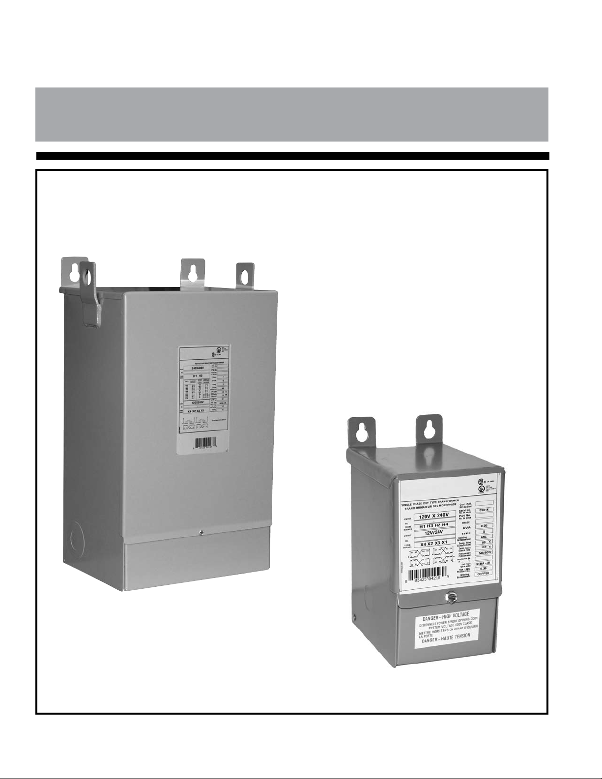
Indoor/Outdoor
Encapsulated Transformers
Single Phase
Up To 50 kVA
*Note: This guide is Trilingual
(English, French, Spanish)*
Literature No.: IOMGE1PH
Issue Date: May 2010
Page 2
Safety Precautions
(1) Do not lift or move a transformer without proper equipment and
experienced personnel.
(2) Do not install the transformer until a full inspection has been
completed.
(3) Use terminals only for electrical connections, and exible connectors
are recommended.
(4) Connections should only be in accordance with the nameplate diagram
or connection drawings.
(5) Make sure all power is disconnected before attempting any work on the
transformer.
(6) Make certain all ground connections are complete and tightened before
energizing the transformer.
(7) Do not attempt to change any taps - primary or secondary, while the
transformer is energized.
(8) Do not change connections when the transformer is energized.
(9) Do not adjust or remove any accessories or cover plates while the
transformer is energized.
Class 1, Division 2, Hazardous Location
Installation Requirements
If this unit is designed for use in Class 1, Division 2, Groups A, B, C & D
hazardous locations then also refer to notes below:
(1) Power, input and output (I/O) wiring must be in accordance with Class 1,
Division 2 wiring methods as per Article 501-10 (b) of the National
Electrical Code.
(2) WARNING - EXPLOSION HAZARD - DO NOT DISCONNECT EQUIPMENT
UNLESS POWER HAS BEEN SWITCHED OFF OR THE AREA IS KNOWN
TO BE NON-HAZARDOUS.
CONTENTS
General Information 3
Handling 3
Receiving & Inspection 3
Storage 3
Installation 3
Ventilation 4
Accessibility 4
Sound Levels 4
Cable Connections 4
Grounding 4
Inspection Before Energization 5
Operation 5
Maintenance 5
Diagrams 1a, 1b and 2 6
- 2 -
Page 3

INSTALLATION, OPERATION AND MAINTENANCE
OF ENCAPSULATED TRANSFORMERS
GENERAL
Encapsulated transformers are manufactured to
provide optimum performance for a lifetime of
uninterrupted service. Careful attention to the following
instructions is recommended for safe and reliable
operation.
Installation, operation and maintenance of
transformers should be performed by qualied
persons, familiar with electrical apparatus and the
potential hazards involved.
Warning: Danger! There is the potential of electric
shock whenever working in or around electrical
equipment such as transformers. Power must
be shut off before any work is conducted on a
transformer.
As with any electrical device, transformers
must be installed according to the requirements
of the national, and local electrical codes. Refer
to ANSI/IEEE C57-94 may also be referred to for
recommended installation, application, operation and
maintenance of dry-type transformers.
STORAGE
Transformers that will not be immediately
installed and energized, should be stored in a clean
dry environment away from any environmental
airborne contaminants.
It is recommended that transformers be stored in
a heated building, in the original shipping packaging.
INSTALLATION
All encapsulated transformers are supplied with a
NEMA 3R enclosure. NEMA 3R units may be installed
indoors, or outdoors where applicable.
For any outdoor location, the appropriate
applicable codes must be followed including cable
installation and hardware suitable for outdoor service.
Water tight couplings must be used at the knockouts.
Encapsulated transformers must be located in
an upright position on walls, posts, beams or other
locations capable of supporting their weight.
If encapsulated units are to be either stored or
installed outdoors, the unit must be oriented vertically
with the wiring compartment down to prevent the
ingress of moisture.
HANDLING
Transformers are either shipped in cartons or
palletized. The units on pallets can either be lifted via a
forklift truck or hoisted by the lifting lugs provided.
Appropriate lifting equipment should be used
relative to the size of each transformer. No attempt
should be made to lift or move a transformer from any
points on the unit other than those indicated.
Please Note: On units bolted to the pallets,
please remove the shipping bolts located at the top
mounting holes as well as the one(s) located inside the
wiring compartment.
RECEIVING INSPECTION
Immediately after receiving the transformer, it
should be inspected for any transit damage and for
correctness against the shipping documents.
The unit should be examined for any breaks in its
packaging, dented or damaged enclosures or missing
parts from the packing list.
If any damage is noted, a claim should be led
immediately with the carrier and a second copy of
all pertinent information relative to the order and the
circumstances should be led with the local sales
ofce.
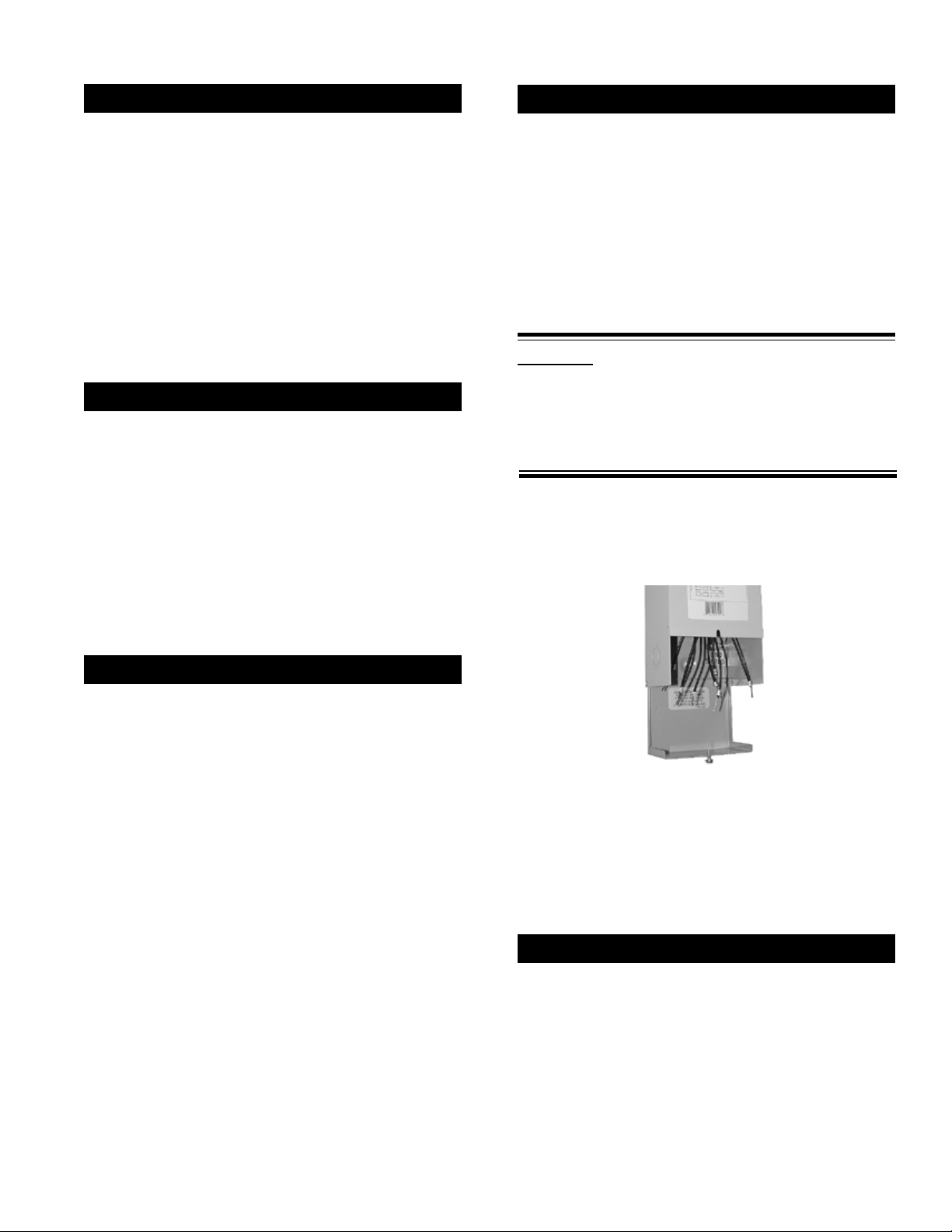
Mounting Instructions (refer to page 6)
1. Select an installation location that is on a
non-combustable surface.
2. The mounting location must allow for air
circulation around the transformer for cooling
purposes. Please refer to the minimum distances
stated in the ventilation section.
3. Using the appropriate mounting template
provided, drill the top two mounting holes on the
mounting surface.
4. Lift the transformer into position and install the top
two mounting bolts.
5. With the transformer hanging on the top two
mounting bolts, level the unit, then with the wiring
compartment cover open, mark and drill the lower
mounting hole(s) into the mounting surface.
6. To provide NEMA 3R protection (protection from
falling rain), the transformer must be mounted
vertically with the mounting tabs facing up.
7. Install the lower mounting bolt, lock washer, at
washer and rubber washer into the lower
mounting hole(s) (refer to Diagram 2).
- 3 -
Page 4
VENTILATION
CABLE CONNECTIONS
Transformers are required to be installed in
an area where they can be cooled by means of the
free circulation of air where the average ambient
temperature is 30°C (86°F) and should not exceed
40°C (104°F) at any time.
Adequate ventilation is essential for transformers
to meet their nameplate kVA capability. All
encapsulated general purpose transformers should be
located at least 2 inches on units up to 10kVA and at
least 4 inches on units over 10kVA, away from walls or
any other obstructions to allow free, clean circulation
of air.
ACCESSIBILTY
accessible for inspection and located accordingly.
However, transformers should not be located in areas
where stored items are likely to interfere with either
natural air convection or the capability to have them
inspected. Passage ways or other areas where people
could be exposed to live parts during inspection should
also be avoided.
Adequate protection should be provided under
any circumstances.
NEC standards require that transformers be
1. Open the wiring compartment by loosening the
cover screw.
2. Terminals should be cleaned and electrical joint
compounds are recommended for use on all
electrical connections.
3. Make the appropriate electrical connection to suit
the desired voltages as per the connection
diagram on the nameplate. This includes the
input connections, output connections and the
ground(s).
WARNING: If this unit is designed for and to be
used in Class 1, Division 2, Groups A, B, C and
D hazardous locations than the power, input and
output (1/0) wiring must be in accordance with
Class 1, Division 2 wiring methods as per Articles
501-10 (b) of the National Electrical Code.
4. Make certain to insulate any unused wire leads
with marrette connectors and electrical tape.
5. Close the wiring compartment and ensure that
the cover screw is tightly secured.
TRANSFORMER SOUND LEVELS
Transformers are an electrically energized
apparatus and by their nature emit sound due to their
component materials.
Transformers are required to meet NEMA
standards for the maximum sound levels permissible.
These sound level standards vary from 40 to 60 DB
and hence, can be an annoyance if located in close
proximity to where people work or reside.
Care should therefore be exercised in selecting
sites for transformers particularly to avoid sensitive
areas like hospitals, classrooms, medical or ofce
facilities.
The following guide lines may be helpful;
Units should be mounted away from corners or
reecting walls or ceilings.
Cable or other exible conduit should be
considered to make connections.
Acoustically absorbing materials could be
considered for walls and ceilings around the unit.
The location of the unit should be located as far
as practical from areas where sound levels could
be considered undesirable.
The connecting cable size is determined from
the line current rating of the transformers primary
and secondary windings. Convenient pre-punched
knockouts are provided on all transformer enclosures,
to facilitate cable entry. (NOTE: potted transformers cannot be
returned if the knockouts have been removed unless the unit has a
manufacturing defect as outlined in the standard warranty policy.)
GROUNDING
All core and coil assemblies are solidly grounded
to the enclosure internally to ensure that all conductive
metal parts have the same potential.
The transformer enclosure in turn should also
be securely and effectively grounded as a safety
precaution. This grounding should be in accordance
with national electrical code standards.
- 4 -
Page 5

INSPECTION BEFORE ENERGIZATION
For the safe and proper operation of the
transformer, we recommend that the following items be
checked for completeness:
a) The insulation resistance, enclosure to primary,
enclosure to secondary and primary to
secondary, should be greater than 10k ohms.
b) Before energizing and connecting any loads,
please measure and verify the output voltage
matches nameplate specications.
c) Ensure correct phase connections. Refer to the
nameplate vector diagram.
d) When windings are connected in parallel (as in
the case of dual voltage primaries), the primary
taps for all coils must be connected to the
identical percentage tap positions to avoid the
shorting of turns. For tap positions, refer to the
nameplate on the transformer.
e) The enclosure should be grounded with the
appropriately sized conductor.
f) The clearance and tightness of all electrical
connections should be checked.
g) For single phase 3-wire 240/120 volt loads, care
must be taken to ensure the neutral current does
not exceed 1/2 of the transformers kVA rating.
OPERATION
For all relatively normal and clean installations,
encapsulated transformers will operate satisfactorily
under normal conditions of energization and load.
For your reference, fully loaded transformers may
be very warm to the touch, particularly on the top of
the unit.
Standards permit the temperatures of the
enclosure to be 65°C over ambient. This represents
normal loading and should not be of concern.
Encapsulated transformers are designed to
operate continuously at their full nameplate kVA rating.
ANSI C57.96 provides guidance for loading
transformers under different conditions including:
Ambient temperatures that are varied from the
ambient temperatures required for transformer
operation.
Short time overload as it relates to time and
temperature and the corresponding loss of life of
the transformer.
Overload that results in a reduction of life
expectancy of the transformer.
If the transformer is experiencing increased
temperatures, the following load characteristics
should be considered immediately:
Rigorous motor starting loads or other impact
type loading for which a specic transformer for
that application is required.
Over-excitation of unit due to excess supply line
voltage or current.
Ambient temperatures above standard.
Overload beyond ANSI C57.96 guidelines.
Harmonic distortions of the supply line voltage
and currents.
MAINTENANCE
Under normal operating conditions and
environments, encapsulated transformers do not
require maintenance. However, periodic care and
inspection is a good practice, particularly if the unit is
exposed to extreme environmental conditions.
Peripheral inspection and external dust and dirt
removal may be carried out while the transformer is
in operation. However, access covers must not be
opened under energized conditions.
The accumulation of ice or snow will not adversly
effect the operation of encapsulated transformers.
However, the accumulation of dust or dirt will effect the
cooling of the transformer and may become a potential
fire hazard.
Internal maintenance must be performed with a
transformer de-energized, isolated and with the
terminals grounded.
The ground connection should be checked to
ensure a low impedance connection.
WARNING: If this unit is designed for and to be
used in Class 1, Division 2, Groups A, B, C, and
D hazardous locations; DO NOT DISCONNECT
EQUIPMENT UNLESS POWER HAS BEEN
SWITCHED OFF OR THE AREA IS KNOWN TO BE
NON-HAZARDOUS
- 5 -
Page 6
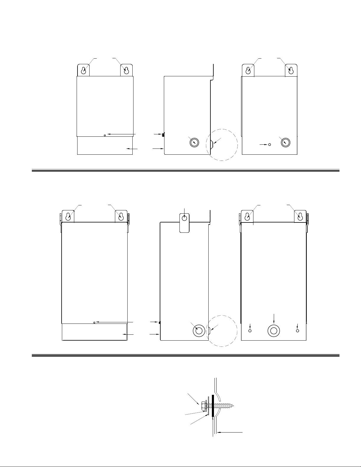
Upper
Mounting
Holes
Upper
Mounting
Holes
FRONT VIEW SIDE VIEW BACK VIEW
Side Knockout Rear Knockout
Wiring
Compartment
Cover
Wiring
Compartment
Cover
Screw
Mtg. Hole
Lower
Mounting
Hole(s)
(see diagram 2 below)
DIAGRAM 1a: NQ0, NQ1, NQ2, NQ3, NQ4 and NQ5 Series Enclosure Mounting for
Upper
Mounting
Holes
Upper
Mounting
Holes
FRONT VIEW SIDE VIEW BACK VIEW
Side Knockout
Rear Knockout
Wiring
Compartment
Cover
Mtg. Hole
Mtg. Hole
Lower
Mounting
Hole(s)
Wiring
Compartment
Cover
Screw
Lifting Tabs
(see diagram 2 below)
Trans former
Enclo sure
Mount ing
Bolt
Lock
Washe r
Flat
Washe r
Rubbe r
Washe r
Single Phase Encapsulated Transformers.
DIAGRAM 1b: NQ6, NQ6A, NQ7 and NQ8 Series Enclosure Mounting for Single Phase
Encapsulated Transformers.
DIAGRAM 2: Lower wiring compartment mounting hole(s), mounting hardware installation
assembly diagram.
- 6 -
Page 7

GUIDE D’INSTALLATION, DE FONCTIONNEMENT ET D’ENTRETIEN
POUR TRANSFORMATEURS ENCAPSULÉS MONOPHASÉS
POUR TRANSFORMATEURS ENCAPSULÉS MONOPHASÉS
POUR L’INTÉRIEUR ET L’EXTÉRIEUR
POUR L’INTÉRIEUR ET L’EXTÉRIEUR
Transformateurs encapsulés
pour l’intérieur et l’extérieur
Monophasé
Jusqu’à 50 kVA
N° de document : IOMGE1PH
Date de publication : Mai 2010
Page 8

Consignes de sécurité
(1) Ne levez pas et ne déplacez pas un transformateur sans disposer de
l’équipement approprié et de personnel expérimenté.
(2) N’installez pas le transformateur tant qu’une inspection complète n’a pas
été effectuée.
(3) N’utilisez les bornes que pour les branchements électriques. Il est recom
mandéd’utiliserdesconnecteursexibles.
(4) Les branchements doivent respecter le schéma de la plaque signalétique ou les
diagrammes de connexion.
(5) Vériezquelasourced’alimentationestcoupéeavantdecommencerà
travailler sur le transformateur.
(6) Vériezquetouteslesliaisonsàlaterresontcomplètesetsontbienserrées
avant de mettre le transformateur sous tension.
(7) Ne tentez pas de changer des prises (primaires ou secondaires)
lorsque le transformateur est sous tension.
(8) Ne changez pas les branchements lorsque le transformateur est sous tension.
(9) Ne réglez pas et ne retirez pas les accessoires ou les plaques de recou vrement
lorsque le transformateur est sous tension.
Exigences pour l’installation dans
des emplacements dangereux de classe 1, division 2
Si cet équipement est conçus pour une utilisation dans des endroits dangereux
et non dangereux de classe 1, division 2, groupes A, B, C, D, réferrer aussi aux
notes suivants:
(1) L’alimentation ainsi que le câblage d’entrée et de sortie (I/O) doivent être
conformes aux méthodes de cablâge des équipements de division 2 décrites dans
l’article 501-10(b) du Code national de l’électricité.
(2) AVERTISSEMENT - RISQUE D’EXPLOSION - NE PAS DÉBRANCHER CET
ÉQUIPEMENT AVANT D'AVOIR COUPER LE COURANT OU QUE
L'ENDROIT EST CONNU POUR ÊTRE NON DANGEREUX.
TABLE DES MATIÈRES
Informations générales 9
Manutention 9
Contrôle de réception 9
Entreposage 9
Installation 9
Ventilation 10
Accessibilité 10
Niveaux de bruit 10
Branchement des câbles 10
Miseàlaterre 10
Inspection avant la mise sous tension 11
Fonctionnement 11
Entretien 11
Schémas 1a, 1b et 2 12
- 8 -
Page 9

INSTALLATION, FONCTIONNEMENT ET ENTRETIEN
DES TRANSFORMATEURS ENCAPSULÉS
INFORMATIONS GÉNÉRALES
Les transformateurs encapsulés sont fabriqués pour
fournir un rendement optimal pendant un cycle de vie de
service continu. Pour un fonctionnement fiable et sans
danger, nous vous recommandons de bien lire les consignes
suivantes.
L’installation, le fonctionnement et l’entretien des
transformateurs doivent être effectués par du personnel
qualiés, familier avec l’appareillage électrique utilisé et des
dangers potentiels qu’il représente.
Avertissement : Danger ! Travailler sur un
transformateur ou autour d'un équipment électrique
similaire présente un risque de choc électrique. Il
est indispensable de mettre hors tension la source
d'alimentation électrique avant d'entreprendre des
travaux sous tension.
Comme pour tout appareil électrique, les transformateurs
doivent être installés en conformité avec les codes nationaux
et locaux de l’électricité. Veuillez egalement vous reporter
a la norme ANSI/IEEE C57-94 pour les recommandations
portant sur l'installation, l'utilisation, le fonctionnement et
l'entretien des transformateurs de type sec.
MANUTENTION
ENTREPOSAGE
Les transformateurs qui ne sont pas immédiatement
installés et mis sous tension doivent être entreposés
dans un endroit propre et sec, à l’abri des contaminants
atmosphériques environnants.
Nous recommandons d’entreposer les transformateurs
dans un immeuble chauffé muni de l'emballage plastiwue
d'origine.
INSTALLATION
Tous les transformateurs encapsulés sont fournis
avec un boîtier NEMA 3R. Les unités NEMA 3R peuvent être
installées à l’intérieur ou à l’extérieur, le cas échéant.
Pour les installations à l’extérieur, les codes en
vigueur qui s’appliquent à l’installation doivent être
respectés, notamment ceux concernant l’installation des
câbles et le matériel convenant à une utilisation extérieure.
Des connecteurs de conduits étanches doivent être utilisés
aux endroits prévus (diaques défonçables).
Les transformateurs encapsulés peuvent être installés
à la verticale sur des murs, des poteaux, des poutres ou
dans d’autres endroits pouvant supporter leur poids.
Si les unités encapsulées sont entreposées ou
installées à l’extérieur, elles doivent être placées à la
verticale, le compartiment de branchement vers le bas, pour
éviter que l’humidité n’y pénètre.
Les transformateurs sont envoyés dans des boîtes ou
en palettes. Les unités sur palettes peuvent être soulevées
à l’aide d’un chariot élévateur à fourche ou levées par les
anneaux de levage fournis.
L’équipement de levage doit être adapté à la taille de
chaque transformateur. En aucun cas, un transformateur
ne doit être soulevé ou déplacé en utilisant d’autres points
d’ancrage que ceux indiqués sur l’appareil.
Remarque : Si le transformateur est xé aux palettes,
retirez les boulons de transport situés dans les orices de
xation supérieurs ainsi le(s) boulon(s) se trouvant dans le
compartiment de branchement.
CONTRÔLE DE RÉCEPTION
Immédiatement après avoir reçu le transformateur, une
inspection doit être effectuée pour vérier la présence de
dommages éventuels survenus durant le transport ainsi que
l’exactitude des documents d’expédition.
L’emballage sera examiné an d’y détecter des bris,
de voir si les boîtiers sont bosselés ou abîmés et si des
pièces inscrites sur le bordereau de marchandises sont
manquantes.
Si des dommages sont constatés, une réclamation
doit immédiatement être effectuée avec le transporteur
et une deuxième copie des renseignements concernant
la commande et les problèmes survenus devrait étre
conservée dans le bureau de vente local.
Instructions de montage (Référez-vous à la page 12)
1. Choisissez pour l’installation un emplacement
dont la surface est non combustible.
2. L’emplacement choisi doit permettre à l’air
de circuler librement pour assurer le
refroidissement de l’appareil. Reportez-vous
aux distances de dégagement minimales
indiquées dans la section Ventilation.
3. En vous servant du gabarit de montage appro
prié, percez les deux trous de xation du haut
sur la surface de xation.
4. Soulevez le transformateur jusqu’à sa position
de montage dénitive et xez les deux boulons
de xation du haut.
5. Ouvrez le couvercle du compartiment de
branchement et marquez le ou les trous
de xation du bas, puis percez la surface de
xation.
6. Pour obtenir une protection NEMA 3R
(protection contre la pluie), il faut monter le
transformateur verticalement, les pattes de
xation vers le haut.
7. Fixez le boulon de xation du bas, la rondelle de
blocage, la rondelle plate et la rondelle de
caoutchouc dans le ou les trous de xation
du bas (voir schéma 2).
- 9 -
Page 10

VENTILATION
BRANCHEMENT DES CÂBLES
Les transformateurs doivent être installés dans un
endroit où ils pourront être refroidis par la circulation de l’air.
La température ambiante moyenne doit être de 30 °C (86 °F)
et ne jamais excéder 40 °C (104 °F).
Une bonne ventilation est indispensable pour que
les transformateurs atteignent la capacité en kVA indiquée
sur leur plaque signalétique. Tous les transformateurs
encapsulés d’usage général doivent être installés à au moins
5 cm (2 po) des murs et autres obstacles pour des unités de
moins de 10 kVA et à au moins 10 cm (4 po) pour des unités
de plus de 10 kVA, pour permettre la libre circulation de l’air
frais.
ACCESSIBILITÉ
Il est prévu par les normes du Code national de
l'électricité que les transformateurs soient accessibles pour
l'inspection et que l'emplacement de l'installation soit choisi
dans cette optique. Ils ne doivent donc pas être installés
dans des locaux renfermant des objets entreposés risquant
de faire obstacle à la circulation de l’air et aux inspections.
Les passages et les endroits dans lesquels des personnes
risquent d’être exposées à des pièces sous tension au cours
de l’inspection doivent également être évités.
Une protection adéquate doit être assurée en toutes
circonstances.
1. Ouvrez le compartiment de branchement en
desserrant la vis du couvercle.
2. Les bornes devraient être nettoyées. Il est
de plus recommandé d’utiliser un produit
d’étanchéité pour raccordements électriques
pour tous les branchements électriques.
3. Effectuez le branchement électrique qui convient
aux tensions désirées en vous conformant au
schéma électrique de la plaque signalétique
(c.-à-d. les branchements pour l’entrée, la sortie
et la mise à la terre).
Avertissement: Si cette unité est conçue pour être
utilisé des endroits dangereux de classe 1, division 2,
groupes A, B, C, D. alors l’alimentation ainsi que le
câblage d’entrée et de sortie (I/O) doivent être
conformes aux méthodes de câblage des équipements
de division 2 décrites dans l’article 501-10 (b) du Code
national de l’électricité.
4. Veillez à bien isoler les ls inutilisés avec des
capuchons de connexion et du ruban isolant.
5. Refermez le compartiment de branchement
et vériez que la vis du couvercle est bien serrée.
NIVEAUX DE BRUIT DU
TRANSFORMATEUR
Les transformateurs sont des appareils alimentés par
l'électricité, et lorsqu'ils sont en fonction, les matériaux qui
sont necessaires à leur construction émettent un certain
bruit.
Les transformateurs doivent respecter les normes
NEMA en matière de niveau sonore. Ces normes varient de
40 à 60 dB, ce qui peut constituer une source de gêne pour
les personnes qui travaillent ou résident à proximité.
Il faut donc choisir avec soin leur emplacement
d’installation et éviter tout particulièrement les zones
sensibles comme les hôpitaux, les écoles, les
établissements médicaux et les bureaux.
Les lignes directrices suivantes pourront se révéler
utiles pour déterminer le bon emplacement d’installation.
Les unités doivent être installées loin des
angles et des murs ou plafonds rééchissants.
Pour les branchements, pensez à utiliser
des câbles ou autres conduits exibles.
Pensez à installer des matériaux acoustiques
absorbants sur les murs et les plafonds se
trouvant autour du transformateur.
Le transformateur doit se trouver aussi loin
que possible des zones pour lesquelles le bruit
pourrait constituer une gêne.
La taille du câble de branchement dépend du courant
nominal des enroulements primaires et secondaires du
transformateur. Des disques defonçables sont fournies avec
tous les transformateurs pour faciliter le passage du câble.
(REMARQUE : les transformateurs encapsulés dont les disques défonçables
ont été retirées ne pourront être retournés sauf si un défaut de fabrication
couvert par la garantie a été détecté.)
MISE À LA TERRE
Toutes les piéces métalliques du noyau-bobines,
non-porteuses de courant, sont reliées à la terre, via le
connecteur de mise à la terre. L'intégrité équipotentielle y
est maintenue.
Pour des raisons de sécurité, le boîtier du
transformateur doit lui aussi être adéquatement relié à la
terre. La mise à la terre doit être effectuée en conformité
avec les normes du Code national électrique.
- 10 -
Page 11

INSPECTION AVANT LA MISE
SOUS TENSION
Pour un fonctionnement adéquat et sans danger du
transformateur, nous recommandons que les éléments
suivants soient également vériés :
a) La résistance d’isolation, de la bobine à l'enroulement
primaire, de la bobine à l'enroulement secondaire
et de l'enroulement primaire au secondaire doit être
supérieure à 10 kilohms.
b) Avant de brancher et de mettre la charge sous tension,
mesurez la tension de sortie pour vérier s’il
correspond aux spécications de la plaque
signalétique.
c) Assurez-vous de brancher les phases conformément
au diagramme vectoriel de la plaque signalétique.
d) Lorsque les enroulements sont branchés en parallèle
(comme dans le cas d’enroulements primaires à
bitension), les prises primaires de toutes les bobines
doivent être branchées au même pourcentage de
positions de prises pour éviter que les spires ne soient
court-circuitées. Pour connaître les positions des
prises, consultez la plaque signalétique du
transformateur.
e) Le boîtier doit être mis à la terre à l’aide d’un
conducteur d’une taille adaptée.
f) Il faut vérier que chaque branchement électrique est
bien serré et sufsamment dégagé.
g) Dans le cas de charges monophasées à 3 conducteurs
de 240/120 volts, il est nécessaire de vérier que le
courant de neutre n’excède pas la moitié du régime
nominal en kVA du transformateur.
FONCTIONNEMENT
Dans tous les cas d’installation normale et bien
réalisée, les transformateurs encapsulés fonctionnent
normalement dans des conditions normales de mise sous
tension et de charge.
Pour votre information, un transformateur chargé peut
s’avérer très chaud au toucher, particulièrement la partie
supérieure de l'appareil.
Les normes permettent que les boîtiers de ce type
d’appareil puissent atteindre jusqu’à 65 °C de plus que la
température ambiante. Cette chaleur indique une charge
normale et ne doit pas vous inquiéter.
Les transformateurs encapsulés sont conçus pour
fonctionner en permanence selon la pleine capacité de kVA
indiquée sur leur plaque signalétique.
ENTRETIEN
Dans des conditions de fonctionnement et des
environnements normaux, les transformateurs encapsulés
ne nécessitent aucun entretien. Il est cependant
recommandé de procéder à un entretien et une inspection
de routine, particulièrement si l’unité est exposée à des
conditions climatiques extrêmes.
Une inspection des éléments externes et un nettoyage
de la poussière et de la saleté accumulées sur le boîtier
peuvent être effectués lorsque le transformateur fonctionne.
Cependant, les couvercles d’accès ne doivent pas être
ouverts lorsque l’appareil est sous tension.
L’accumulation de glace ou de neige ne compromet
pas le fonctionnement des transformateurs encapsulés.
Par contre, l’accumulation de poussière ou de saleté gène
le refroidissement de l’appareil et peut provoquer un risque
d’incendie.
L’entretien interne doit être effectué sur un
transformateur éteint, isolé, et dont les bornes sont
mises à la terre.
Il est nécessaire de vérifier la liaison à la terre pour
garantir que le branchement est de faible impédance.
AVERTISSEMENT - Si cette unité est conçue pour être
utilise des endroits dangereux de classe 1, division
2, groupes A, B, C, D. – NE PAS DÉBRANCHER CET
ÉQUIPEMENT AVANT D'AVOIR COUPER LE COURANT
OU QUE L'ENDROIT EST CONNU POUR ÊTRE NON
DANGEREUX.
Les normes C57.96 de l’ANSI donnent des
directives pour le chargement des transformateurs dans
différentes conditions, notamment :
démarrage de moteur brusque ou autre type de
charge brusque pour lequel un transformateur
spécique pour ce type d'application est requis.
ur-excitation de l’unité à la suite d’une surtension de
l'alimentation ou d'une surcharge.
températures ambiantes supérieures à la
normale.
surcharge supérieure aux directives C57.96
de l’ANSI.
distorsions harmoniques de la tension de la ligne
d'alimentation et du courant.
- 11 -
Page 12

Trous de
montage
supérieurs
Trous de
montage
supérieurs
VUE AVANT VUE LATÉRALE VUE ARRIÈRE
Disque défonçable arrière
Trou de
montage
Trou(s) de
montage
inférieur(s)
(Reportez-vous au diagramme 2, ci-dessous.)
Couvercle du
compartiment de
branchement
Vis du couvercle
du compartiment
de branchement
Disque défonçable latérale
SCHÉMA 1a : Montage du boîtier des séries NQ0, NQ1, NQ2, NQ3, NQ4 et NQ5 pour
Trous de
montage
supérieurs
Trous de
montage
supérieurs
VUE AVANT VUE LATÉRALE VUE ARRIÈRE
Disque défonçable latérale
Disque défonçable arrière
Couvercle du
compartiment de
branchement
Trou de montage
Trou(s) de
montage
inférieur(s)
Vis du couvercle
du compartiment
de branchement
Languettes de soulèvement
Trou de montage
(Reportez-vous au diagramme 2, ci-dessous.)
Boîtier du transformateur
Boulon de fixation
Rondelle de blocage
Rondelle plate
Rondelle de caoutchouc
transformateurs encapsulés monophasés.
SCHÉMA 1b : Montage du boîtier des séries NQ6, NQ6A, NQ7 et NQ8 pour
transformateurs encapsulés monophasés.
SCHÉMA2:Trou(s)dexationinférieur(s)ducompartimentdebranchement,
schémad’assemblagedelaquincailleriedexation.
- 12 -
Page 13

GUÍA DE INSTALACIÓN, OPERACIÓN Y MANTENIMIENTO
TRANSFORMADORES MONOFÁSICOS CON GABINETE
TRANSFORMADORES MONOFÁSICOS CON GABINETE
PARA INTERIORES Y EXTERIORES
PARA INTERIORES Y EXTERIORES
Transformadores con gabinete
para interiores y exteriores
Monofásico
Hasta 50 kVA
N.º de folleto: IOMGE1PH
Fecha de emisión: De mayo de 2010
Page 14

Precauciones de seguridad
(1) No levante ni traslade un transformador sin equipo apropiado ni personal
experimentado.
(2) No instale el transformador hasta que se haya realizado una inspección
completa.
(3) Ut i l ic e ú n i c am e n t e l os te rm i na l e s pa ra co ne x io ne s e l éc t ri ca s .
Serecomiendanconectoresexibles.
(4) Las conexiones solo deben realizarse siguiendo el diagrama de la placa de
identicaciónolosdiagramasdeconexión.
(5) Asegúrese de que toda la energía esté desconectada antes de iniciar cualquier
trabajo en un transformador.
(6) Asegúrese de que todas las conexiones a tierra estén completas y ajustadas antes
de dar energía al transformador.
(7) No intente cambiar ninguna derivación, primaria o secundaria, mientras el
transformador esté energizado.
(8) No cambie las conexiones cuando el transformador esté bajo excitación.
(9) No ajuste ni retire ningún accesorio ni cubierta protectora mientras el
transformador está energizado.
Sitio peligroso de clase 1, división 2
Requisitos para la instalación
Si esta unidad es diseñada para uso en locaciones peligrosas Clase 1, División 2,
GruposA,B,C&D,entoncesreérasetambiénalasnotassiguientes:
(1) El cableado de energía, entrada y salida (I/O, por sus siglas en inglés) debe cumplir
con los métodos de cableado de clase 1, división 2, de acuerdo con el Artículo
501-10 (b) del Código Eléctrico Nacional.
(2) ADVERTENCIA - PELIGRO DE EXPLOSIÓN - NO DESCONECTE EL EQUIPO A MENOS
QUE SE HAYA APAGADO LA ENERGÍA O QUE EL ÁREA NO SEA PELIGROSA.
CONTENIDO
Información general 15
Manipulación 15
Recepción e inspección 15
Almacenamiento 15
Instalación 15
Ventilación 16
Accesibilidad 16
Niveles de ruido 16
Conexiones de cables 16
Conexión a tierra 16
Inspección antes de la energización 17
Operación 17
Mantenimiento 17
Diagramas 1a, 1b y 2 18
- 14 -
Page 15

INSTALACIÓN, OPERACIÓN Y MANTENIMIENTO
DE LOS TRANSFORMADORES CON GABINETE
GENERAL
Los transformadores con gabinete se fabrican para
brindar un rendimiento óptimo con una vida útil de servicio
ininterrumpido. Se recomienda seguir al pie de la letra las
siguientes instrucciones para lograr una operación segura y
conable.
La instalación, la operación y el mantenimiento de
los transformadores deben ser realizados por personas
calicado, que tengan conocimiento sobre aparatos eléctricos
y los posibles riesgos que conllevan.
Advertencia: ¡Peligro! Existe el riesgo de descarga
eléctrica cuando trabaja con o cerca de equipos
eléctricos como los transformadores. Se debe
desconectar la energía antes de realizar cualquier
trabajo en un transformador.
Al igual que con cualquier dispositivo eléctrico, los
transformadores se deben instalar de acuerdo con los
requisitos de los códigos eléctricos nacionales y locales.
También puede consultar la norma ANSI/IEEE C57-94 para
conocer las pautas recomendadas de instalación, aplicación,
operación y mantenimiento de transformadores de tipo seco.
MANIPULACIÓN
Los transformadores se envían en cajas de cartón o
en tarimas. Las unidades en las tarimas se pueden elevar
con un montacargas o se pueden levantar con las argollas
de elevación provistas.
Se debe utilizar equipo de elevación apropiado para el
tamaño de cada transformador. No se debe intentar elevar
ni trasladar un transformador desde ningún otro punto de la
unidad que no sean los puntos indicados.
Tenga en cuenta: En las unidades atornilladas a las
tarimas, retire los pernos de envío que se encuentran en
los oricios de montaje superiores y los que se encuentran
dentro del compartimiento de cableado.
INSPECCIÓN DE RECEPCIÓN
Inmediatamente después de recibir el transformador,
se debe inspeccionar para detectar cualquier daño
transitorio y para vericar la exactitud de los datos en
comparación con los documentos de envío.
Se debe examinar la unidad para detectar cualquier
rotura en el embalaje, abolladura o daño en los recintos o
piezas faltantes de la lista de empaquetado.
Si se observa algún daño, se debe presentar un
reclamo de inmediato ante la empresa de transporte y
una segunda copia ante la ocina local de ventas con
toda la información pertinente con respecto al pedido y las
circunstancias.
ALMACENAMIENTO
Los transformadores que no se instalarán y
energizarán de inmediato, se deben guardar en un ambiente
seco y limpio, alejados de cualquier contaminante ambiental
en suspensión.
Se recomienda guardar los transformadores en un
lugar con calefacción, en su embalaje de envío original.
INSTALACIÓN
Todos los transformadores con gabinete vienen
provistos de un recinto NEMA 3R. Las unidades NEMA 3R
se pueden instalar en interiores, exteriores o donde sea
necesario.
Para una ubicación en exteriores, se deben seguir los
códigos aplicables adecuados, que incluyen la instalación de
los cables y el equipo apropiado para el servicio exterior. Se
deben usar acoplamientos herméticos en los troqueles.
Los transformadores con gabinete se deben ubicar en
posición vertical apoyados en paredes, postes, vigas u otros
lugares que puedan soportar el peso.
Si las unidades encapsuladas se van a guardar
o instalar en exteriores, la unidad se debe orientar
verticalmente con el compartimiento de cableado hacia
abajo para impedir el ingreso de humedad.
Instrucciones de montaje (Reerase a la página 18)
1. Seleccione un lugar para la instalación que esté
sobre una supercie no inamable.
2. La ubicación de montaje debe permitir la
circulación de aire alrededor del transformador
para que pueda enfriarse. Consulte las distancias
mínimas especicadas en la sección de ventilación.
3. Con la plantilla de montaje apropiada que viene con
el equipo, perfore dos oricios de montaje superior en
la supercie de montaje.
4. Levante el transformador hasta colocarlo en su
posición e instale los dos pernos de montaje superiores.
5. Con el transformador colgando sobre los dos pernos
de montaje superiores, nivele la unidad y luego, con el
compartimiento de cableado abierto, marque y perfore
los oricios de montaje inferiores en la supercie de
montaje.
6. Para brindar protección NEMA 3R (protección contra
lluvia), el transformador debe estar montado
verticalmente con las lengüetas de montaje orientadas
hacia arriba.
7. Instale el perno de montaje inferior, la arandela de
presión, la arandela plana y la arandela de goma en
el oricio de montaje inferior (ver Diagrama 2).
- 15 -
Page 16

VENTILACIÓN
Los transformadores se deben instalar en una área
donde se puedan enfriar mediante la libre circulación de aire
y donde la temperatura ambiente promedio sea de 30°C
(86°F) y no supere los 40°C (104°F) en ningún momento.
La ventilación adecuada es esencial para que los
transformadores alcancen la capacidad de kVa que gura
en la placa de identicación. Todos los transformadores con
gabinete para usos generales se deben ubicar por lo menos
a 2 pulgadas (5 cm) en las unidades de hasta 10 kVa y a por
lo menos 4 pulgadas (10 cm) en las unidades superiores a
10 kVa, alejados de paredes o de otras obstrucciones para
permitir la libre y despejada circulación de aire.
ACCESIBILIDAD
sean accesibles para la inspección y que se ubiquen
adecuadamente para tal n. Sin embargo, los
transformadores no se deben ubicar en áreas donde
es probable que los elementos almacenados intereran
con la convección natural del aire o con la capacidad de
inspeccionarlos. También se deben evitar los pasillos u
otras áreas donde la gente pueda estar expuesta a piezas
energizadas durante la inspección.
Se debe proporcionar protección adecuada bajo
cualquier circunstancia.
Las normas NEC exigen que los transformadores
CONEXIONES DE CABLES
1. Abra el compartimiento de cableado aojando el
tornillo de la cubierta.
2. Los terminales se deben limpiar, y se recomienda
usar compuestos de empalme eléctrico en todas las
conexiones eléctricas.
3. Realice las conexiones eléctricas apropiadas para
adaptarse a los voltajes deseados de acuerdo con el
diagrama de conexión que gura en la placa de
identicación. Esto incluye las conexiones de entrada,
de salida y la conexión a tierra.
PELIGRO: Si esta unidad es diseñada para o va ser
usada en, locaciones peligrosas Clase 1, División 2,
Grupos A, B, C & D, entonces las conexiones eléctricas
de entrada y salida deben estar de acuerdo con los
métodos de conexión para Clase 1, División 2, según los
Artículos 501-10 (b) del Código Nacional de Electricidad.
4. Asegúrese de aislar todos los cables conductores no
utilizados con conectores Marrette y cinta aisladora.
5. Cierre el compartimiento de cableado y verique que
el tornillo de la cubierta esté rmemente ajustado.
NIVELES DE RUIDO
DEL TRANSFORMADOR
Los transformadores son aparatos energizados
eléctricamente y por su naturaleza emiten ruidos debido a
sus materiales componentes.
Los transformadores deben cumplir las normas NEMA
para los niveles máximos de ruido permitidos. Estos niveles
de ruido varían de 40 a 60 DB, y por lo tanto, pueden ser
molestos si se encuentran en las inmediaciones de los
lugares donde viven o trabajan personas.
Se debe tener cuidado al elegir los sitios para los
transformadores, especialmente para evitar áreas sensibles
como hospitales, escuelas, centros médicos u ocinas.
Las siguientes pautas pueden ser útiles.
Las unidades deben montarse alejadas de
esquinas o de paredes o cielorrasos que
produzcan reejos.
Los cables u otros conductos exibles deben
tenerse en cuenta para realizar conexiones.
Los materiales absorbentes acústicamente se podrían
tener en cuenta para las paredes y los cielorrasos
alrededor de la unidad.
La unidad debe ubicarse lo más alejada posible
de las áreas donde los niveles de ruido podrían
considerarse indeseables.
El tamaño del cable de conexión se determina con la
potencia de corriente de línea de los bobinados primarios
y secundarios de los transformadores. Se suministran
prácticos troqueles previamente perforados en todos los
recintos de los transformadores para facilitar la entrada de
los cables.
devolver si se han retirado los troqueles, a menos que la unidad
tenga un defecto de fabricación, como se describe en la política de
garantía estándar).
(NOTA: Los transformadores envasados no se pueden
CONEXIÓN A TIERRA
Todos los conjuntos de núcleo y bobina se conectan
sólidamente a tierra al recinto, en forma interna, para
garantizar que todas las piezas metálicas conductoras
tengan el mismo potencial.
El recinto del transformador también debe tener
una conexión a tierra segura y ecaz como precaución
de seguridad. Esta conexión a tierra debe cumplir con las
normas de los códigos eléctricos nacionales.
- 16 -
Page 17

INSPECCIÓN ANTES DE LA
ENERGIZACIÓN
Para la operación segura y apropiada del
transformador, recomendamos vericar que se hayan
completado los siguientes pasos:
a) La resistencia del aislamiento, el recinto hasta el
primario, el recinto hasta el secundario y del primario
al secundario, debe ser superior a 10 k ohmios.
b) Antes de energizar y conectar cualquier carga, mida y
verique que el voltaje de salidacoincida con las
especicaciones de la placa de identicación.
c) Verique que las conexiones de fase sean correctas.
Consulte el diagrama vectorial de la placa de
identicación.
d) Cuando los bobinados se conectan en paralelo (como
en el caso de primarios de doble voltaje), las
derivaciones primarias de todas las bobinas se deben
conectar en las posiciones de derivación con
porcentaje idéntico para evitar el cortocircuito de
las marchas. Para conocer las posiciones de
derivación, consulte la placa de identicación
del transformador.
e) El recinto debe estar conectado a tierra con el
conductor del tamaño apropiado.
f) Se debe vericar que todas las conexiones eléctricas
respeten la distancia de seguridad y que estén
ajustadas.
g) Para las cargas monofásicas, de 3 hilos, de 240/
120 voltios, se debe tener cuidado para garantizar
que la corriente neutra no supere 1/2 de la potencia
de kVA de los transformadores.
Si el transformador presenta aumento de temperatura,
se deben considerar de inmediato las siguientes
características de carga:
Cargas de arranque del motor rigurosas u otra carga
de tipo impacto para la cual se requiere un
transformador especíco para esa aplicación.
Excitación excesiva de la unidad debido a un exceso
del voltaje o la corriente de la línea de alimentación.
Temperaturas ambiente superiores a las estándar.
Sobrecarga superior a la indicada en las pautas
ANSI C57.96.
Distorsiones armónicas del voltaje y las corrientes
MANTENIMIENTO
En condiciones normales de funcionamiento y
ambientales, los transformadores con gabinete no requieren
mantenimiento. Sin embargo, es una buena práctica realizar
el cuidado y la inspección periódica, especialmente si la
unidad está expuesta a condiciones ambientales extremas.
La inspección periférica y la remoción del polvo
y la suciedad externa se deben realizar mientras el
transformador está en funcionamiento. Sin embargo, no se
deben abrir las cubiertas de acceso si el transformador está
energizado.
La acumulación de hielo o nieve no afectará
negativamente el funcionamiento de los transformadores
con gabinete. Sin embargo, la acumulación de polvo o
suciedad afectará el enfriamiento del transformador y podría
representar un riesgo de incendio.
OPERACIÓN
Para todas las instalaciones relativamente normales
y limpias, los transformadores con gabinete funcionarán
satisfactoriamente en condiciones normales de energización
y carga.
Para su referencia, los transformadores totalmente
cargados pueden estar muy calientes al tacto,
especialmente en la parte superior de la unidad.
Las normas permiten que las temperaturas del recinto
sean de 65ºC con respecto a la temperatura ambiente.
Esto representa una carga normal y no debe ser motivo de
preocupación.
Los transformadores con gabinete están diseñados
para operar en forma continua a la potencia total de kVA que
gura en la placa de identicación.
La norma ANSI C57.96 ofrece pautas para la carga de
transformadores en diferentes condiciones, entre ellas:
Temperaturas ambiente que varían de
las temperaturas ambientes exigidas para la
operación de transformadores.
Sobrecarga de corta duración que se relaciona
con el tiempo y la temperatura y la
correspondiente pérdida de la vida útil del
transformador.
Sobrecarga que provoque la reducción de
la expectativa de vida útil del transformador.
El mantenimiento interno se debe realizar con un
transformador desenergizado, aislado y con los
terminales con conexión a tierra.
Se debe verificar la conexión a tierra para garantizar
que sea una conexión de baja impedancia.
PELIGRO: Si esta unidad es diseñada para o va ser
usada en, locaciones peligrosas Clase 1, División 2,
Grupos A, B, C & D, NO DESCONECTE EL EQUIPO
A NO SER QUE LA ELECTRICIDAD HAYA SIDO
DECONECTADA O HASTA ESTAR SEGURO QUE EL
AREA ES FUERA DE PELIGRO.
- 17 -
Page 18

Orificios
superiores
de montaje
Orificios
superiores
de montaje
VISTA POSTERIOR
VISTA LATERAL
VISTA FRONTAL
Cubierta del
compartimiento
de cableado
Tornillo de la
cubierta del
compartimiento
de cableado
Troquel lateral
Agujero(s)
inferior(es)
de montaje
Agujero de
montaje
Troquel trasero
(ver Diagrama 2 abajo)
DIAGRAMA 1a: Montaje de recintos de serie NQ0, NQ1, NQ2, NQ3, NQ4 y NQ5 para
Orificios
superiores
de montaje
VISTA FRONTAL VISTA LATERAL VISTA POSTERIOR
Troquel lateral
Troquel trasero
Cubierta del
compartimiento
de cableado
Agujero de montaje
Agujero(s)
inferior(es)
de montaje
Tornillo de la
cubierta del
compartimiento
de cableado
Lengüetas de elevación
Orificios
superiores
de montaje
Agujero de montaje
(ver Diagrama 2 abajo)
Recinto del transformador
Perno de montaje
Arandela de presión
Arandela plana
Arandela de goma
transformadores con gabinete monofásicos.
DIAGRAMA 1b: Montaje de recintos de serie NQ6, NQ6A, NQ7 y NQ8 para
transformadores con gabinete monofásicos.
DIAGRAMA2: Oriciosdemontajeinferioresdelcompartimientodecableado,
diagrama del conjunto de instalación del equipo.
- 18 -
 Loading...