

Page 1
HPS TRIBUNE
THREE PHASE, DRIVE ISOLATION TRANSFORMERS
With today’s technological advances in solid-state power control devices, the use of AC and DC variable
speed drives has proliferated in many industrial markets. General purpose distribution transformers are not
adequate for this type of application.
HPS Drive Isolation Transformers are designed to meet the rugged demands of both AC and DC variable
speed drives and also to provide the required voltage change. The separate primary and secondary
windings provide electrical isolation between the incoming line and the SCR load. The windings are designed
to withstand overcurrent of 150% of the rated load for 60 seconds or 200% of the rated load for 30 seconds.
(A duty cycle of one start for every two hours is permitted.)
Drive Isolation Transformers are sized to match standard motor horsepower and voltage ratings.
Standard sizes range from 5 to 600 HP in six standard voltages. Non-standard sizes and voltages are available
upon request.
SELECTION INSTRUCTIONS
Select the Drive Isolation Transformer according to the recommendations from the motor drive system
manufacturer or supplier. If this information is unavailable, use the table below as a guide for selecting the
transformer kVA for a required motor horsepower.
Motor Transformer
H.P. kVA
5 7.5
7.5 11
10 14
15 20
20 27
25 34
30 40
40 51
50 63
Motor Transformer
H.P. kVA
75 93
100 118
125 145
150 175
200 220
250 275
300 330
400 440
500 550
60 75
600 660
1
Page 2
SECTION 4
ENERGY EFFICIENT
DRIVE ISOLATION TRANSFORMERS
HPS Tr i b u n e
Energy Efcient (TP1/C802.2) Drive Isolation Transformers
ALUMINUM AND COPPER WOUND FEATURES
THREE PHASE SPECIFICATIONS
7.5 to 175 kVA 220 to 660 kVA
Efciency Meets TP1/C802.2 efciencies at 35% of rated load.
UL Listed File: E112313 File: E112313
CSA Certied File: LR3902 File: LR3902
Frequency 60 Hz 60 Hz
Insulation System 220°C (150°C rise)
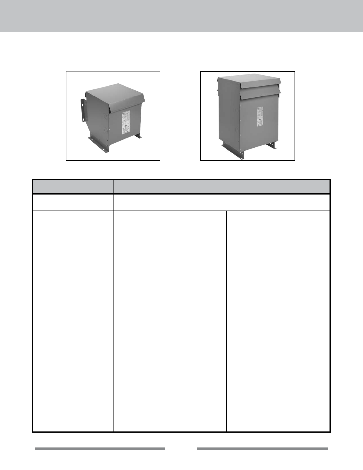
Enclosure Type Heavy Duty Ventilated NEMA Type 3R
Enclosure Finish ANSI 61 Grey, UL50 ANSI 61 Grey, UL50
Neutral Neutral terminal for eld connection (on
Standard Primary Taps Refer to wiring diagrams for details. Refer to wiring diagrams for details.
Termination Front accessible separate high and low voltage
Thermostat Standard on all units. Standard on all units.
Conduit Knock-Outs Standard on all units. None
Impedance Typically 3 to 6% Typically 3 to 6%
Mounting Floor mounting available on all units. Wall &
Efciencies are calculated under a linear load prole.
200°C (130°C rise) on some Copper units up to 40kVA
Optional NEMA 4, 4X(stainless steel) and 12
applicable units).
terminations, suitable for copper and aluminum
are provided for easy cable installation.
ceiling mount available on units up to 750 lbs.
Refer to selection tables for details.
220°C (150°C rise)
(Optional 115°C and 80°C rise available)
Heavy Duty Ventilated NEMA Type 3R
Optional NEMA 4, 4X(stainless steel) and 12
Neutral terminal for eld connection (on
applicable units).
Front accessible separate high and low
voltage terminations, suitable for copper
and aluminum are provided for easy cable
installation.
Floor mounting only.
Seismic Meets all seismic parameters for IBC 2009 and
NBCC 2005 for ground level installations only for
all locations in North America.
Short Circuit Withstand Meets UL and CSA short circuit withstand
requirements.
2
Meets all seismic parameters for IBC 2009
and NBCC 2005 for ground level installations
only for all locations in North America.
Meets UL and CSA short circuit withstand
requirements.
Page 3

SECTION 4
ENERGY EFFICIENT
DRIVE ISOLATION TRANSFORMERS
TERMINATION DETAILS
THREE PHASE, ALUMINUM AND COPPER TERMINATION - LUGS OR PADS
kVA
7.5 Lugs Lugs Lugs Lugs Lugs Lugs Lugs Lugs
11 Lugs Lugs Lugs Lugs Lugs Lugs Lugs Lugs
14 Lugs Lugs Lugs Lugs Lugs Lugs Lugs Lugs
20 Lugs Lugs Lugs Lugs Lugs Lugs Lugs Lugs
27 Lugs Lugs Lugs Lugs Lugs Lugs Lugs Lugs
34 Lugs Lugs Lugs Lugs Lugs Lugs Lugs Lugs
40 Lugs Lugs Lugs Lugs Lugs Lugs Lugs Lugs
51 Lugs Lugs Lugs Lugs Lugs Lugs Lugs Lugs
63 Lugs Lugs Lugs Lugs Lugs Lugs Lugs Lugs
75 Lugs Lugs Lugs Lugs Lugs Lugs Lugs Lugs
93 Lugs Lugs Lugs Lugs Lugs Lugs Lugs Lugs
118 Diagram 1A Diagram 1A Diagram 1A Lugs Lugs Lugs Lugs Lugs
145 Diagram 1A Diagram 1A Diagram 1A Lugs Lugs Lugs Lugs Lugs
175 Diagram 2 Diagram 1A Diagram 1A Lugs Lugs Lugs Lugs Lugs
220 Diagram 2 Diagram 2 Diagram 2 Diagram 1A Diagram 1A Lugs Lugs Lugs
275 Diagram 2 Diagram 2 Diagram 2 Diagram 1A Diagram 1A Diagram 1A Diagram 1A Lugs
330 Diagram 2 Diagram 2 Diagram 2 Diagram 2 Diagram 1A Diagram 1A Diagram 1A Diagram 1A
440 Diagram 3 Diagram 3 Diagram 3 Diagram 3 Diagram 3 Diagram 3 Diagram 1B Diagram 1B
550 Diagram 3 Diagram 3 Diagram 3 Diagram 3 Diagram 3 Diagram 3 Diagram 3 Diagram 3
660 Diagram 3 Diagram 3 Diagram 3 Diagram 3 Diagram 3 Diagram 3 Diagram 3 Diagram 3
208 230 240 380 460 480 575 600
VOLTAGE
DIAGRAM 1
1A - 0.437” Dia.
1B - 0.56” Dia.
0.56” Dia. (Qty. 2)
3
0.56” x 1.0” Slot (Qty. 4)
DIAGRAM 3DIAGRAM 2
 Loading...