

Page 1
*#1 *#1
*#1
*#1 *#1
Model :/
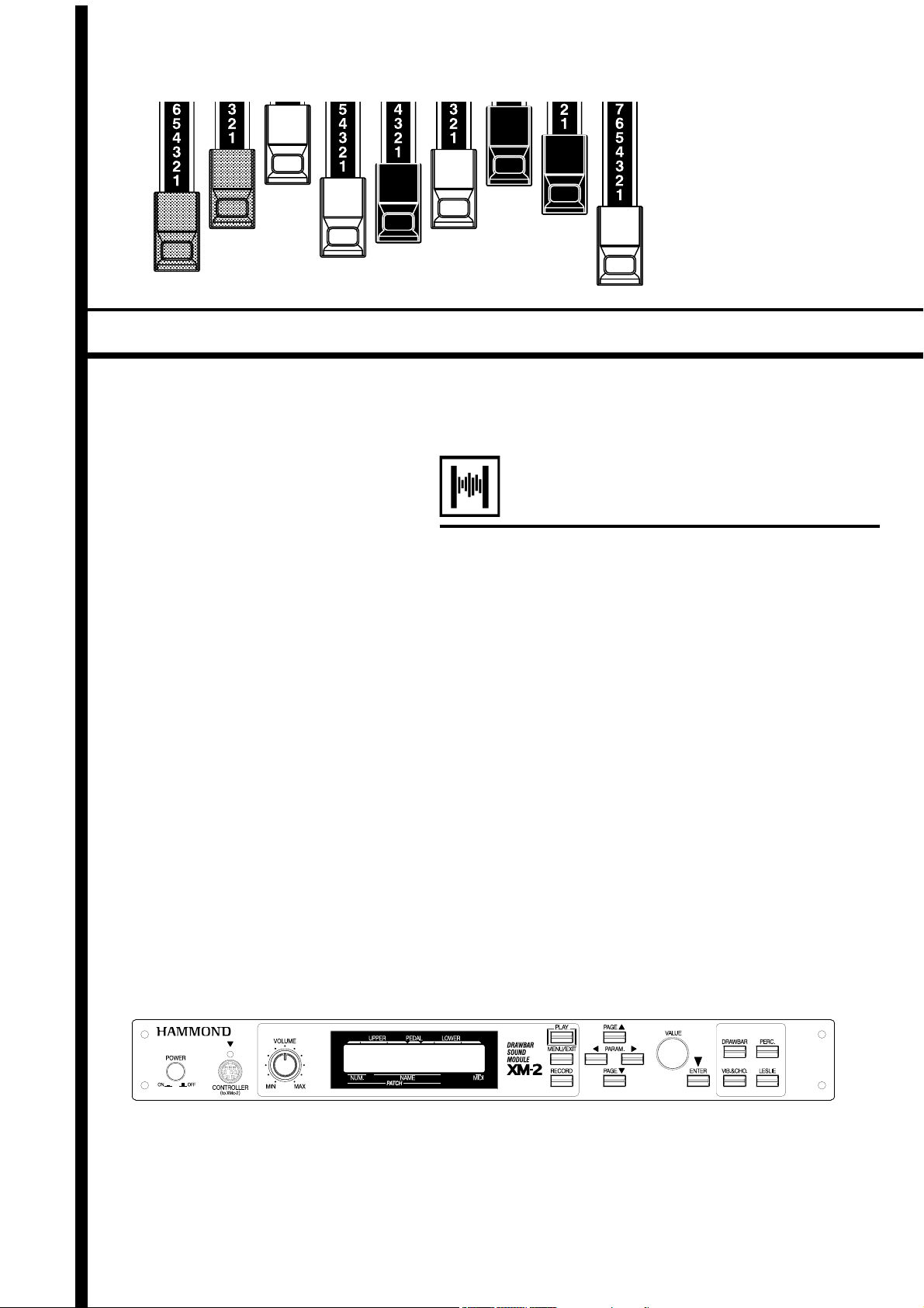
Thank you, and congratulations on your choice of
a Hammond XM-2, Drawbar Sound Module.
In order to get the most out of this instrument for
many years to come, please take the time to read
this manual in full.
Owner’s Manual
Page 2
IMPORTANT SAFETY INSTRUCTIONS
Before using this unit, please carefully read this “Safety Instructions” and use it correctly.
Please be sure to keep this manual at hand even after reading it once.
This “Safety Instructions” section contains very important points for securing your safety. Strictly observe the instructions, please.
In this manual, the degrees of dangers and damages are classified and explained as follows:
WARNING
as instructed.
This sign shows there is a risk of injury or material damage if this unit is not properly
This sign shows there is a risk of death or severe injury if this unit is not properly used
CAUTION
used as instructed.
*Material damage here means a damage to the room, furniture or animals or pets.
WARNING
Do not open (or modify in any way) the unit or its AC adap-
tor.
Do not attempt to repair the unit, or replace parts in it (except
when this manual provides specific instructions directing you
to do so). Refer all servicing to your retailer, the nearest
Hammond, or an authorized Hammond distributor, as listed
on the “Service” page.
Never use or store the unit in places that are:
Subject to temperature extremes (e.g., direct sunlight in
an enclosed vehicle, near a heating duct, on top of heatgenerating equipment)
Damp (e.g., baths, washrooms, on wet floors)
Humid
Exposed to rain
Dusty
Subject to high levels of vibration.
Be sure to use only the AC adaptor supplied with the unit.
Also, make sure the line voltage at the installation matches
the input voltage specified on the AC adaptor’s body. Other
AC adaptors may use a different polarity, or be designed for a
different voltage, so their use could result in damage, malfunction, or electric shock.
Do not excessively twist or bend the power cord, nor place
heavy objects on it. Doing so can damage the cord, producing
severed elements and short circuits. Damaged cords are fire
and shock hazards!
This unit, either alone or in combination with an amplifier
and headphones or speakers, may be capable of producing
sound levels that could cause permanent hearing loss. Do not
operate for a long period of time at a high volume level, or at
a level that is uncomfortable. If you experience any hearing
loss or ringing in the ears, you should immediately stop using
the unit, and consult an audiologist.
Immediately turn the power off, remove the AC adaptor from
the outlet, and request servicing by your retailer, the nearest
Hammond, or an authorized Hammond distributor, as listed
on the “Service” page when:
The AC adaptor, the power-supply cord, or the plug has
been damaged; or
If smoke or unusual odor occurs
Objects have fallen into, or liquid has been spilled onto
the unit; or
The unit has been exposed to rain (or otherwise has be-
come wet); or
The unit does not appear to operate normally or exhibits a
marked change in performance.
In households with small children, an adult should provide
supervision until the child is capable of following all the rules
essential for the safe operation of the unit.
Protect the unit from strong impact.
(Do not drop it!)
Do not force the unit’s power-supply cord to share an outlet
with an unreasonable number of other devices. Be especially
careful when using extension cords - the total power used by
all devices you have connected to the extension cord’s outlet
must never exceed the power rating (watts/amperes) for the
extension cord. Excessive loads can cause the insulation on
the cord to heat up and eventually melt through.
Before using the unit in a foreign country, consult with your
retailer, the nearest Hammond, or an authorized Hammond
distributor, as listed on the “Service” page.
Do not put anything that contains water (e.g., flower vases)
on this unit. Also, avoid the use of insecticides, perfumes, alcohol, nail polish, spray cans, etc., near the unit. Swiftly wipe
away any liquid that spills on the unit using a dry, soft cloth.
Do not allow any objects (e.g., flammable material, coins,
pins); or liquids of any kind (water, soft drinks, etc.) to penetrate the unit.
*#1 :/Owner’s Manual
Page 3
CAUTION
The unit and the AC adaptor should be located so their loca-
tion or position does not interfere with their proper ventilation.
Always grasp only the plug on the AC adaptor cord when plug-
ging into, or unplugging from, an outlet or this unit.
At regular intervals, you should unplug the AC adaptor and
clean it by using a dry cloth to wipe all dust and other accumulations away from its prongs. Also, disconnect the power
plug from the power outlet whenever the unit is to remain
unused for an extended period of time. Any accumulation of
dust between the power plug and the power outlet can result
in poor insulation and lead to fire.
Try to prevent cords and cables from becoming entangled.
Also, all cords and cables should be placed so they are out of
the reach of children.
Never climb on top of, nor place heavy objects on the unit.
Never handle the AC adaptor or its plugs with wet hands
when plugging into, or unplugging from, an outlet of this
unit.
Before moving the unit, disconnect the AC adaptor and
all cords coming from external devices.
Before cleaning the unit, turn off the power and unplug
the AC adaptor from the outlet.
Whenever you suspect the possibility of lightning in your
area, disconnect the AC adaptor from the outlet.
In case if in the future your instrument gets too old to play or mal-
functions beyond repair, please observe the instructions of this
mark, or, if any question, be sure to contact your dealer or your
nearest town or municipal office for its proper disposal.
Introduction
Page 4

IMPORTANT - PLEASE READ
Power Supply
Do not use this unit on the same power circuit with any device that
will generate line noise (such as an electric motor or variable light-
ing system).
The AC adaptor will begin to generate heat after long hours of con-
secutive use. This is normal, and is not a cause for concern.
Before connecting this unit to other devices, turn off the power to
all units. This will help prevent malfunctions and/or damage to speak-
ers or other devices.
Placement
Using the unit near power amplifiers (or other equipment contain-
ing large power transformers) may induce hum. To alleviate the prob-
lem, change the orientation of this unit; or move it farther away
from the source of interference.
This device may interfere with radio and television reception. Do
not use this device in the vicinity of such receivers.
Noise may be produced if wireless communications devices, such
as cell phones, are operated in the vicinity of this unit. Such noise
could occur when receiving or initiating a call, or while conversing.
Should you experience such problems, you should relocate such
wireless devices so they are at a greater distance from this unit, or
switch them off.
Do not expose the unit to direct sunlight, place it near devices that
radiate heat, leave it inside an enclosed vehicle, or otherwise sub-
ject it to temperature extremes. Also, do not allow lighting devices
that normally are used while their light source is very close to the
unit (such as a piano light), or powerful spotlights to shine upon the
same area of the unit for extended periods of time. Excessive heat
can deform or discolor the unit.
When moved from one location to another where the temperature
and/or humidity is very different, water droplets (condensation) may
form inside the unit. Damage or malfunction may result if you at-
tempt to use the unit in this condition. Therefore, before using the
unit, you must allow it to stand for several hours, until the conden-
sation has completely evaporated.
Do not allow rubber, vinyl, or similar materials to remain on the
unit for long periods of time. Such objects can discolor or other-
wise harmfully affect the finish
Maintenance
To clean the unit, use a dry, soft cloth; or one that is slightly damp-
ened.
To remove stubborn dirt off plastic parts, use a cloth impregnated
with a mild, non-abrasive detergent. Afterwards, be sure to wipe
the unit thoroughly with a soft, dry cloth. Try to wipe the entire
surface using an equal amount of strength, moving the cloth along
with the grain of the wood. Rubbing too hard in the same area can
damage the finish.
Never use benzine, thinners, alcohol or solvents of any kind, to avoid
the possibility of discoloration and/or deformation.
Additional Precautions
Please be aware that the contents of memory can be irretrievably
lost as a result of a malfunction, or the improper operation of the
unit. To protect yourself against the risk of losing important data,
we recommend that you periodically save a backup copy of impor-
tant data you have stored in the unit’s memory in another MIDI
device (e.g., a sequencer).
Unfortunately, it may be impossible to restore the contents of data
that was stored in another MIDI device (e.g., a sequencer) once it
has been lost. Hammond assumes no liability concerning such loss
of data.
Use a reasonable amount of care when using the unit’s buttons, slid-
ers, or other controls; and when using its jacks and connectors. Rough
handling can lead to malfunctions.
When connecting / disconnecting all cables, grasp the connector
itself - never pull on the cable. This way you will avoid causing
shorts, or damage to the cable’s internal elements.
To avoid disturbing your neighbors, try to keep the unit's volume at
reasonable levels. You may prefer to use headphones, so you do not
need to be concerned about those around you (especially when it is
late at night).
When you need to transport the unit, package it in the box (includ-
ing padding) that it came in, if possible. Otherwise, you will need to
use equivalent packaging materials.
Do not paste stickers, decals, or the like to this instrument. Peeling
such matter off the instrument may damage the exterior finish.
*#1 :/Owner’s Manual
Page 5
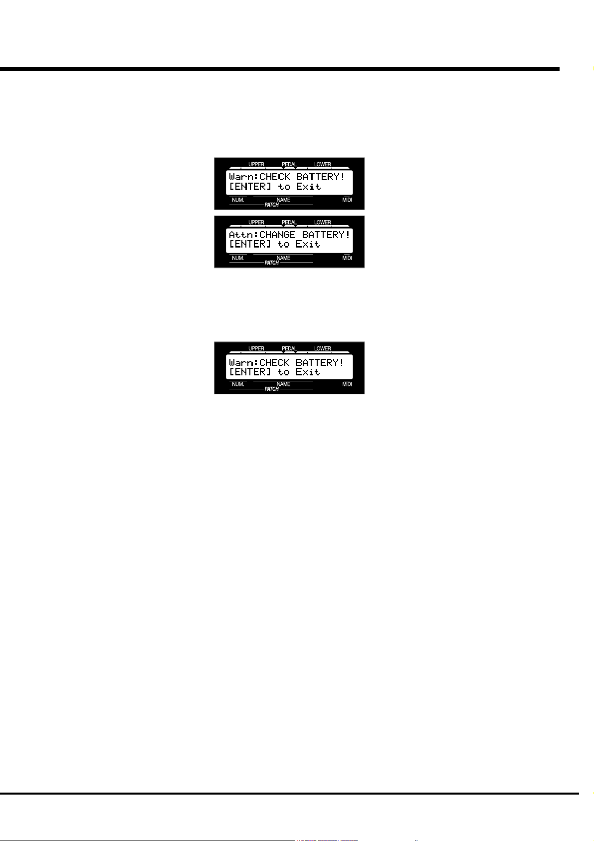
BATTERY BACK UP
Your XM-2 uses a battery-backed RAM to remember your changes to the Parameters.
When the battery voltage becomes low, the Display will show:
If you see these messages, you should immediately back up your parameter changes, if
you have made any. If there is no battery installed in the unit, or if the battery is
compeletely dead, the Display will show:
After the above message is displayed, the XM-2 will re-initialize itself, and the factory
default settings will be restored. Therefore, it is a good idea to periodically save your
data to a sequencer.
CAUTION: Ask your dealer or store for the details how to change the batter-
ies.
Introduction
Page 6

Table Of Contents
IMPORTANT SAFETY INSTRUCTIONS.................................. 2
IMPORTANT - PLEASE READ ............................................... 4
BATTERY BACK UP .............................................................. 5
MAIN FEATURES ................................................................. 9
NAMES AND FUNCTIONS .................................................. 10
Front Panel................................................................................... 10
Rear Panel ................................................................................... 11
HOOK-UP........................................ 13
BASIC HOOK-UP ................................................................ 14
CONNECTION USING A SIMPLE MIDI KEYBOARD ............................... 14
CONNECTION USING A SIMPLE MIDI KEYBOARD AND THE XMc-2 .... 15
CONNECTION USING A MULTI-FUNCTIONAL MIDI KEYBOARD ............ 16
CONNECTION USING TWO MIDI KEYBOARDS ..................................... 16
CONNECTION USING MULTIPLE MIDI KEYBOARDS AND THE XMc-2 .. 17
CONNECTION OF LESLIE SPEAKER ................................... 18
BASIC CONNECTION OF THE LESLIE SPEAKER .................................. 18
MIDI CONTROL OF LESLIE SPEAKER .................................................. 18
TURN ON AND PLAY ...................... 19
TURN ON THE POWER....................................................... 20
HOW TO TURN THE POWER ON ......................................................... 20
BACK-UP ............................................................................................ 20
RESET TO THE FACTORY SETTINGS .................................................. 20
LISTEN TO THE DEMONSTRATION .................................... 21
PLAY BY THE PATCH ......................................................... 22
HOW TO CALL OUT THE PATCHES ..................................................... 22
WHAT IS “PART” ?.............................................................................. 22
PLAY WITH THE CONTROLLERS ....................................... 23
PITCH BEND ....................................................................................... 23
EXPRESSION PEDAL ........................................................................... 23
FOOT SWITCH .................................................................................... 23
CREATE YOUR OWN SOUNDS ........................................... 24
SELECT PATCH 128. ........................................................................... 24
MAKE THE DRAWBAR REGISTRATION ............................................... 24
ADD PERCUSSION .............................................................................. 24
ADD EFFECTS ..................................................................................... 25
VIBRATO AND CHORUS ............................................................... 25
LESLIE ......................................................................................... 25
RECORD TO THE PATCH ..................................................................... 26
SETTING UP ................................... 27
SOUND ENGINE STRUCTURE ............................................ 28
SYSTEM STRUCTURE OF XM-2 .......................................................... 28
HOW TO USE THE PANEL BUTTONS ................................. 30
EXAMPLE: Set Upper 8' of Drawbar registration at 5. .......................... 30
DRAWBAR (DRAWBAR registration) ................................. 31
DRAWBARS™ .................................................................... 32
WHITE DRAWBARS ............................................................................ 33
BLACK DRAWBARS ............................................................................ 33
BROWN DRAWBARS .......................................................................... 33
PEDAL DRAWBARS ............................................................................ 33
DRAWBAR REGISTRATION PATTERNS ............................................... 34
PERC (PERCussion)........................................................... 36
NOTE .................................................................................................. 36
DRAWBAR CANCEL ..................................................................... 36
VIB & CHO (VIBrato and CHOrus) ..................................... 37
LESLIE ............................................................................... 38
PATCH ................................................................................ 39
NAME THE PATCH .............................................................................. 39
RECORD A NEW PATCH ...................................................................... 40
DISPLAY AND ITS OPERATION..... 41
PLAY MODE ....................................................................... 42
HOW TO READ THE DISPLAY ............................................................. 42
PANEL BUTTON MODE ...................................................... 43
HOW TO READ THE DISPLAY ............................................................. 43
BUTTON OPERATION IN THIS MODE................................................... 43
MENU MODE ..................................................................... 44
HOW TO READ THE DISPLAY ............................................................. 44
BUTTON OPERATION IN THIS MENU................................................... 44
FUNCTION MODE .............................................................. 45
HOW TO READ THE DISPLAY ............................................................. 45
BUTTON OPERATION IN THIS MODE................................................... 45
EXAMPLE: Adjusting the DECAY TIME of the Percussion [FAST] ......... 46
SHORT CUT TO THE FUNCTION MODE .............................. 48
EXAMPLE: Move to the Percussion Function Mode. ........................... 48
*#1 :/Owner’s Manual
Page 7

IN THIS MANUAL:
NOTE:s and appear frequently.
The NOTE: is a supplementary explanation.
The are explanations of terms and
applications.
SETTING THE PARAMETERS ....... 49
DRAWBAR ......................................................................... 50
Setting the Manual (LOWER and UPPER) ................................................. 50
Setting the PEDAL .................................................................................... 51
PATCH ................................................................................ 52
PATCH NAME ........................................................................................... 52
PATCH LOAD ............................................................................................ 52
PATCH NUMBERS .....................................................................................52
EFFECTIVE USE OF LINK-LOWER/PEDAL ............................................ 53
WHEN LINK LOWER/PEDAL IS ON: .............................................. 53
WHEN LINK LOWER/PEDAL IS OFF: ............................................. 53
CONTROL........................................................................... 54
PITCH BEND ............................................................................................. 54
MODULATION ...........................................................................................55
PRESSURE ............................................................................................... 55
EXPRESSION ............................................................................................ 56
FOOT SWITCH .......................................................................................... 57
DISPLAY ...................................................................................................57
ADJUSTING THE EXPRESSION PEDAL ................................................ 58
TUNE ................................................................................. 59
CUSTOM TONEWHEELS .................................................... 60
B-Type ......................................................................................................... 60
Mellow ......................................................................................................... 60
Brite ............................................................................................................. 60
PERCUSS (PERCUSSion) .................................................. 61
LESLIE ............................................................................... 62
CABINET NUMBERS ................................................................................. 62
LESLIE PARAMETERS .............................................................................. 62
RECORD THE CABINETS ..................................................................... 64
OD/VIB (OverDrive / VIBrato) ............................................ 65
OVERDRIVE .............................................................................................. 65
VIBRATO & CHORUS ................................................................................65
EQUALIZ (EQUALIZer) ....................................................... 66
REVERB ............................................................................. 67
MIDI .................................................................................. 68
MIDI TEMPLATE ....................................................................................... 68
MASTER ................................................................................................... 68
MIDI CHANNEL .........................................................................................69
MIDI TEMPLATES AND THEIR PURPOSES .......................................... 70
THE MIDI IN MODES AND THEIR FUNCTIONS ..................................... 70
KEYMAP ............................................................................ 71
SPLIT ....................................................................................................... 71
MANUAL BASS ......................................................................................... 71
WHAT IS SPLIT? ...................................................................................... 71
WHAT IS MANUAL BASS?........................................................................ 71
DEFAULT ............................................................................ 72
SYSTEM ............................................................................ 73
APPENDIX ...................................... 75
Part and MIDI Messages ................................................... 77
MIDI Information ............................................................... 78
Drawbar Data List 1 .......................................................... 79
Drawbar Data List 2 .......................................................... 79
System Exclusive Message ............................................... 80
Global Parameters ............................................................ 81
Patch Parameters.............................................................. 82
Leslie Parameters ............................................................. 84
System Parameters ........................................................... 84
Specifications.................................................................... 86
Demonstration Songs and Composers .............................. 87
Factory Patches ................................................................ 88
SERVICE ............................................................................ 89
Introduction
Page 8

*#1 :/Owner’s Manual
Page 9

MAIN FEATURES
ACCURATELY REPRODUCES THE TONE-WHEEL SOUND.
Your new XM-2 contains (96) independent oscillating digital tone-wheels which accurately repro-
duces the sound of the Vintage B-3.
In addition, this module has full polyphony.
DIGITAL LESLIE / VIBRATO EFFECTS.
The XM-2 module is equipped with a DSP effect generator to simulate the Scanner-Vibrato and the
Leslie Speaker.
The range of sounds that you can create is expanded by the use of Vibrato and Chorus effects, and by
the real sounding Leslie effects which effectively simulates the rotation of the two Rotors which are
present in a traditional Leslie.
8-PIN LESLIE SPEAKER SOCKET.
Your new XM-2 contains an 8-pin Leslie speaker socket for direct connection to our Leslie 21 System
Speakers.
CAN BE EXPANDED BY USE OF EXTERNAL MIDI PRODUCTS.
You can connect your XM-2 with various MIDI instruments and expand its function. You can not
only play it using a single MIDI keyboard but also expand the number of keyboards (Lower Key-
board and Pedal Keyboard) by connecting it with other MIDI keyboards. You can also record your
performance to an external sequencer.
9
Introduction
Page 10
10
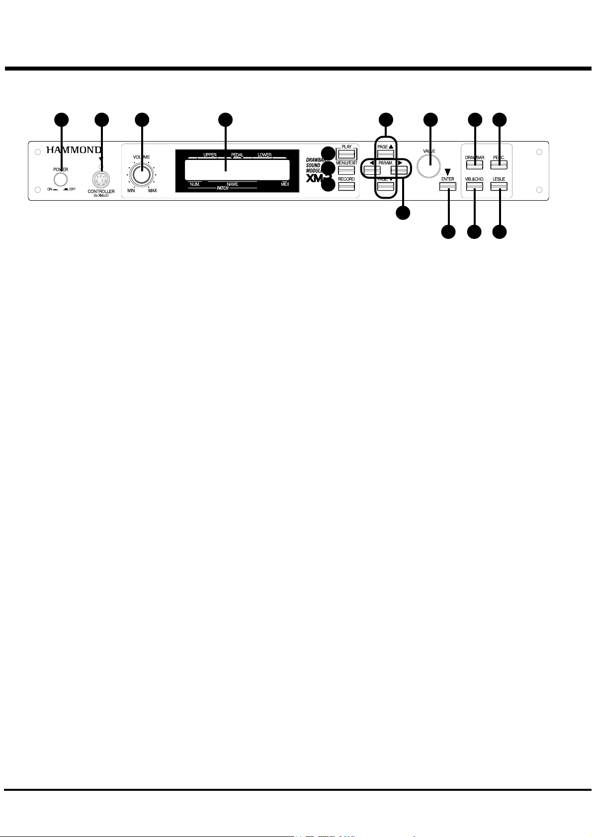
Front Panel
NAMES AND FUNCTIONS
1 2 3 4
FRONT LEFT SIDE
1. POWER Switch
This switches ON/OFF the module.
2. CONTROLLER Jack
This is the terminal for connecting the Drawbar Controller
XMc-2 (to be separately purchased).
Use the exclusive cable HMC-1 for connection.
3. VOLUME Knob
Controls the total volume.
4. DISPLAY
Displays various information.
EDIT BUTTONS
5. PLAY Button
Jumps to the PLAY mode, the basic mode.
8
5
6
7
10. VALUE Knob
Increases and decreases the Patch or value of the selected
parameter.
11. ENTER Button
This is used for deciding the selected items.
10
9
11
12 13
14 15
PANEL BUTTONS
12. DRAWBAR Button
Calls out the Drawbar Registration mode.
13. PERC. Button
Calls out the Percussion Switch mode.
14. VIB. & CHO. Button
Calls out the Vibrato Switch mode.
14. LESLIE Button
Calls out the Leslie Switch mode.
6. MENU/EXIT Button
Recalls the MENU mode. This is also used to return from
each function mode.
7. RECORD Button
Records the Patches.
This is also used for controlling the other recording.
8. PAGE Buttons
Selects Pages in the menu.
9. PARAMETER Buttons
Selects Parameters.
*#1 :/Owner’s Manual
Page 11
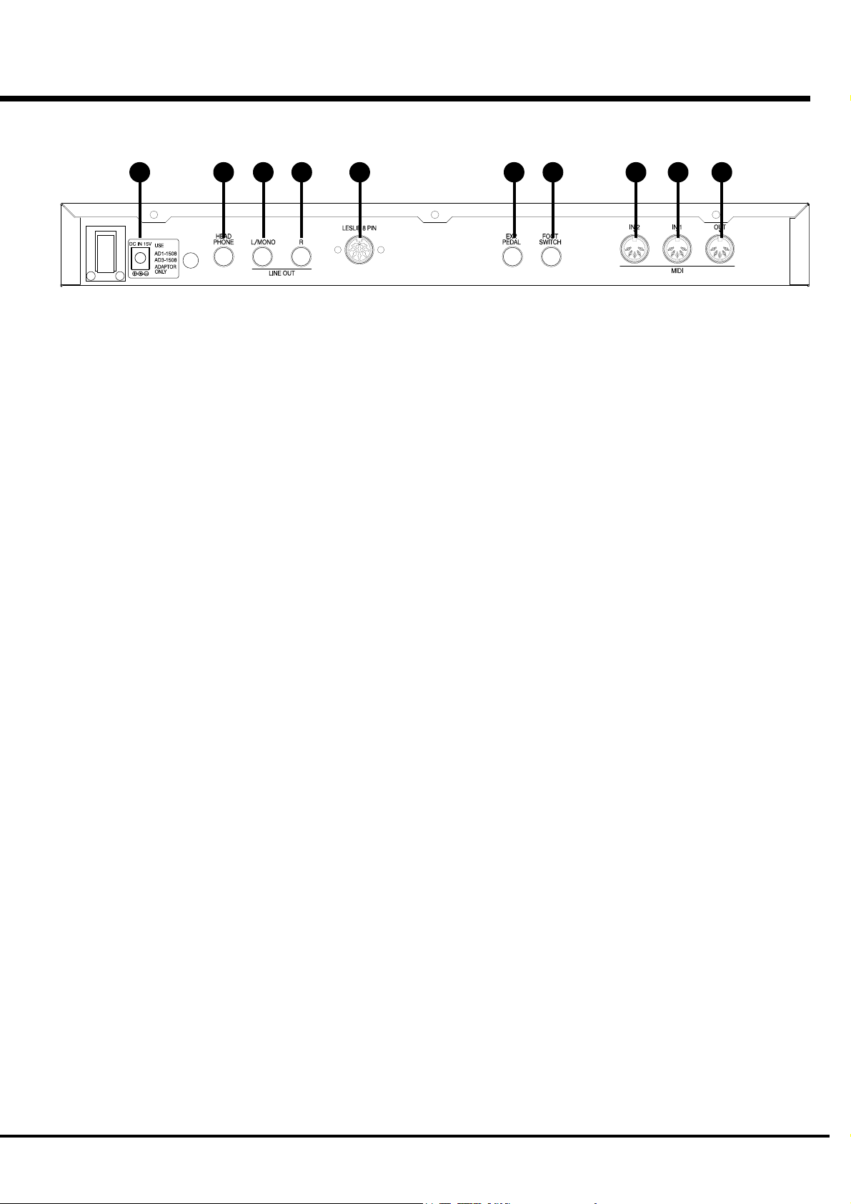
Rear Panel
16 19 17 18 20 21 22 25 24 23
11
POWER SUPPLY
16. DC IN Jack
Connects the attached AC Adaptor AD1-1508 (100 - 120V)
AD3-1508 (220 - 240V).
SOUND OUTPUT TERMINAL
17. LINE OUT L/MONO Jack
If your amplifier has only a single (1) female 1/4" audio
input connector (MONO input), use this Jack.
18. LINE OUT R Jack
This is the Right channel output of the XM-2.
Use the Left and Right output Jacks if your mixer or ampli-
fier has stereo inputs.
Use only the L/MONO terminal, if the input is monaural.
The built-in Leslie Effect is only on L (the left), when the
Leslie Speaker (20) is connected.
19. HEADPHONE Jack
This is for connecting a set of stereo headphones.
Sound is sent out from the LINE-OUTS (17, 18) and
LESLIE 8PIN (20), also when this terminal is used.
The built-in LESLIE is only on L (the left), when the
LESLIE SPEAKER (20) is connected.
20. LESLIE 8PIN Jack
This is for connecting the Leslie 21 System Speaker.
Read “CONNECTING THE LESLIE SPEAKER” for more
details.
CONTROLLER TERMINAL
21. EXP. PEDAL Jack
This terminal is for the Expression Pedal (V-20R - optional).
You can control the volume while you play.
22. FOOT SWITCH Jack
This terminal is for the Foot Switch (FS-9H - optional).
You can switch the speed of the Leslie effect and the Patch,
etc. while playing.
MIDI
23. MIDI OUT Jack
Outputs the internal information of this unit and the play-
ing information from the MIDI IN terminal (according to
the setting).
24. MIDI IN 1 Jack
Receives the MIDI information.
The factory setting of this terminal is for receiving the in-
formation through the MIDI channel.
You can also set it for receiving only a specified part infor-
mation, regardless of the channel.
25. MIDI IN 2 Jack
Receives the MIDI information.
The factory setting of this terminal is for receiving the in-
formation through the MIDI channel.
You can also set it for receiving only a specified part infor-
mation, regardless of the channel.
Introduction
Page 12

12
*#1 :/Owner’s Manual
Page 13

HOOK-UP
13
*#1 :/ Owner’s Manual
Page 14
14
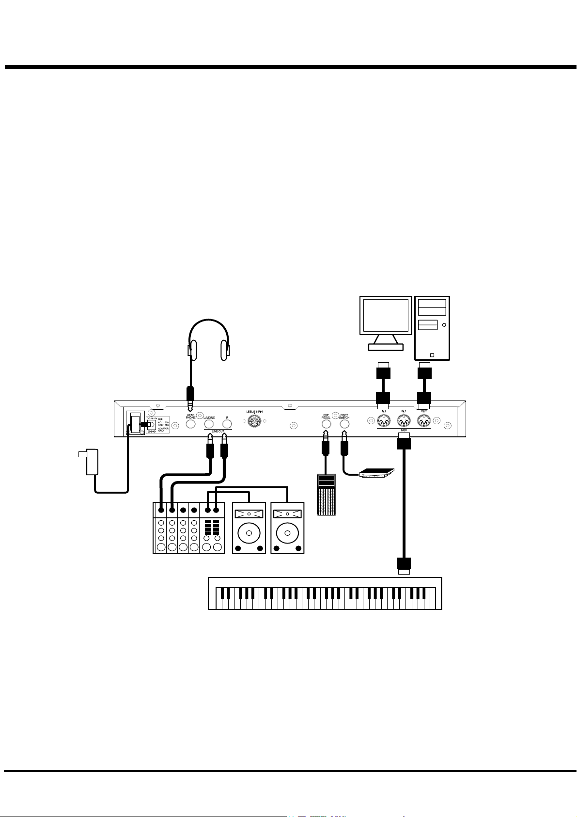
BASIC HOOK-UP
Be sure to turn OFF the power of your XM-2 and connecting devices before you do the
hookup.
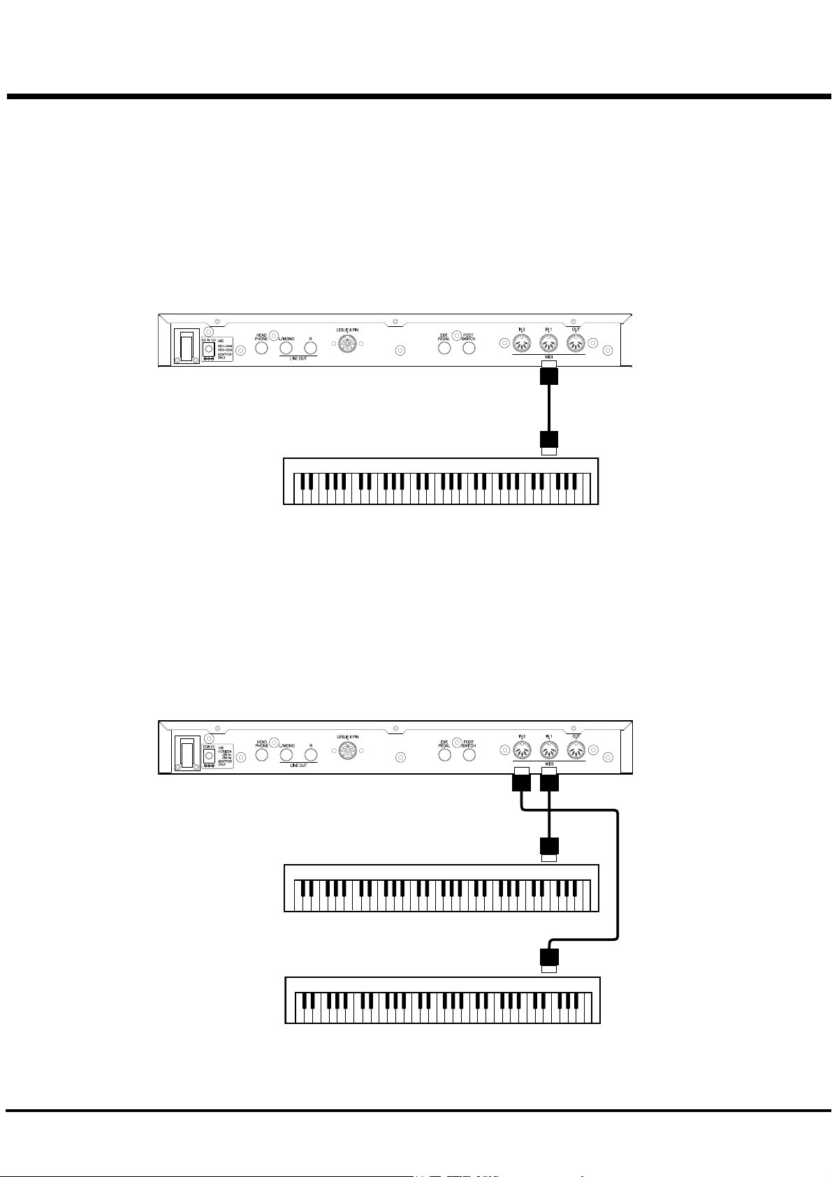
CONNECTION USING A SIMPLE MIDI KEYBOARD
This is the simplest example.
You can play as many as 3 parts by a single-manual MIDI Keyboard, using the Split and Manual Bass
functions of the XM-2.
Set the MIDI Keyboard for sending a single channel. (The channel number does not matter.)
Call out “Single KBD” by the MIDI Template (P. 68) of this unit.
In this case of connection, you can record to and play out of an external sequencer.
AC Adaptor
(Provided)
Stereo
Headphones
To Mixer, Amplifier etc.
MIDI Sequencer,
Computer etc.
(optional)
Foot Switch
(optional)
Expression
Pedal (optional)
MIDI OUT
*#1 :/Owner’s Manual
MIDI Keyboard
Page 15
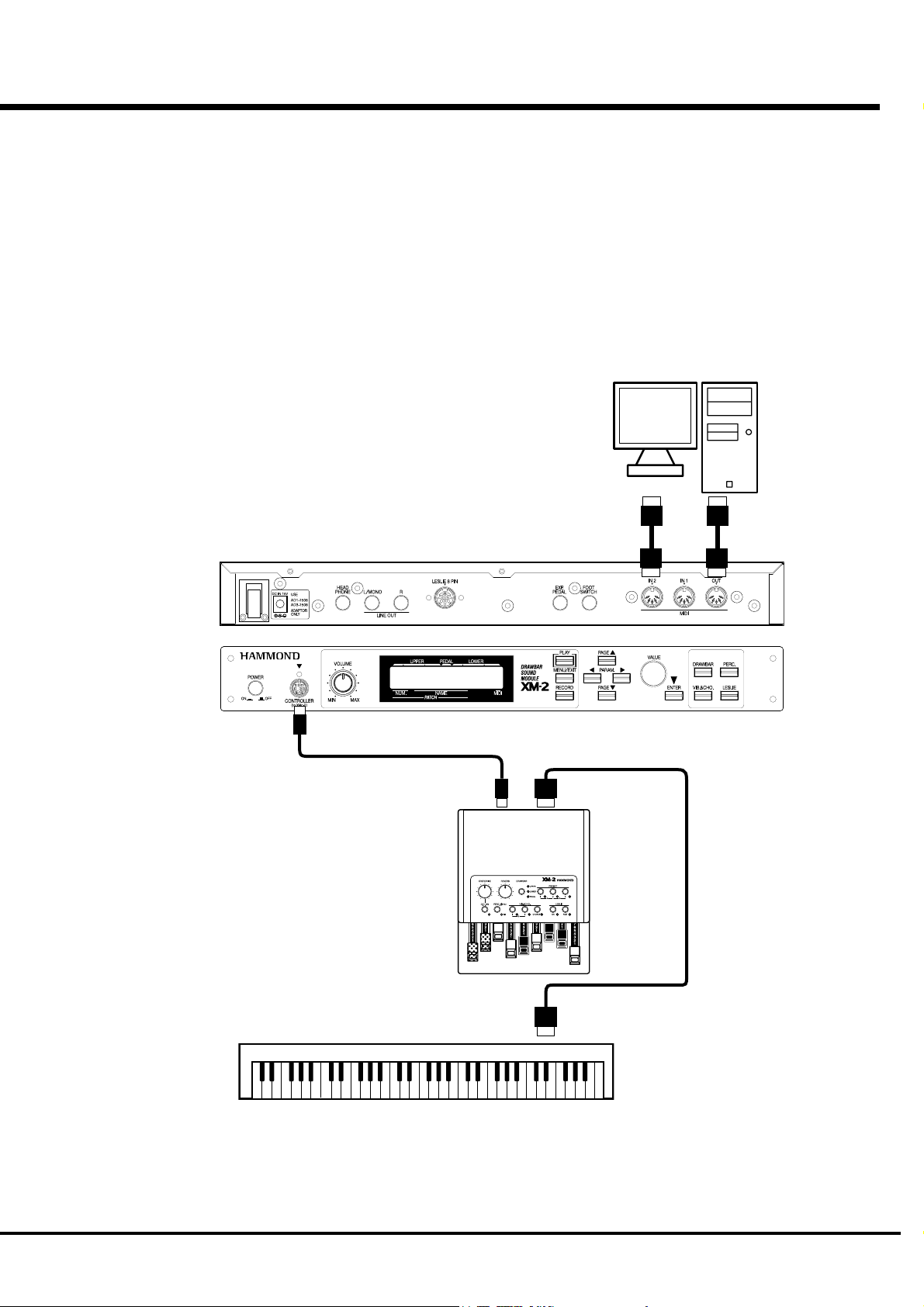
CONNECTION USING A SIMPLE MIDI
KEYBOARD AND THE XMc-2
The hook-up example shown below is for making the Drawbar Registration change at hand
using the Drawbar Controller XMc-2.
Set the MIDI Keyboard for sending a single channel. (The channel number does not matter.)
Call out “Single KBD” by the MIDI Template (P. 68) of this unit.
In this case of connection, you can record to and play out of an external sequencer.
MIDI Sequencer,
Computer etc.
(optional)
15
TO XM-2
MIDI Keyboard
MIDI IN
MIDI OUT
Hook-Up
Page 16
16
CONNECTION USING A MULTI-FUNCTIONAL
MIDI KEYBOARD
This hook-up shown below is for using a MIDI Keyboard that can send data to multiple MIDI
channels or an electronic organ that has multiple keyboards.
Call out “By Channel” by the MIDI template (P. 68) of this unit.
Set appropriate values for the MIDI channels on this unit and on each keyboard. The default
settings of the receiving channels on this unit are Upper = 1, Lower = 2, and Pedal = 3.
MIDI Keyboard (for UPPER / LOWER / PEDAL)
MIDI OUT
CONNECTION USING TWO MIDI KEYBOARDS
This hook-up example is for using two MIDI Keyboards; one for playing UPPER and the other
for playing LOWER part.
Set each of the MIDI Keyboard to send a single channel. (The channel numbers do not matter.)
Call out “2KBD for L&U” by the MIDI Template (P. 68) of this unit.
MIDI Keyboard (for UPPER)
MIDI OUT
MIDI Keyboard (for LOWER)
MIDI OUT
*#1 :/Owner’s Manual
Page 17
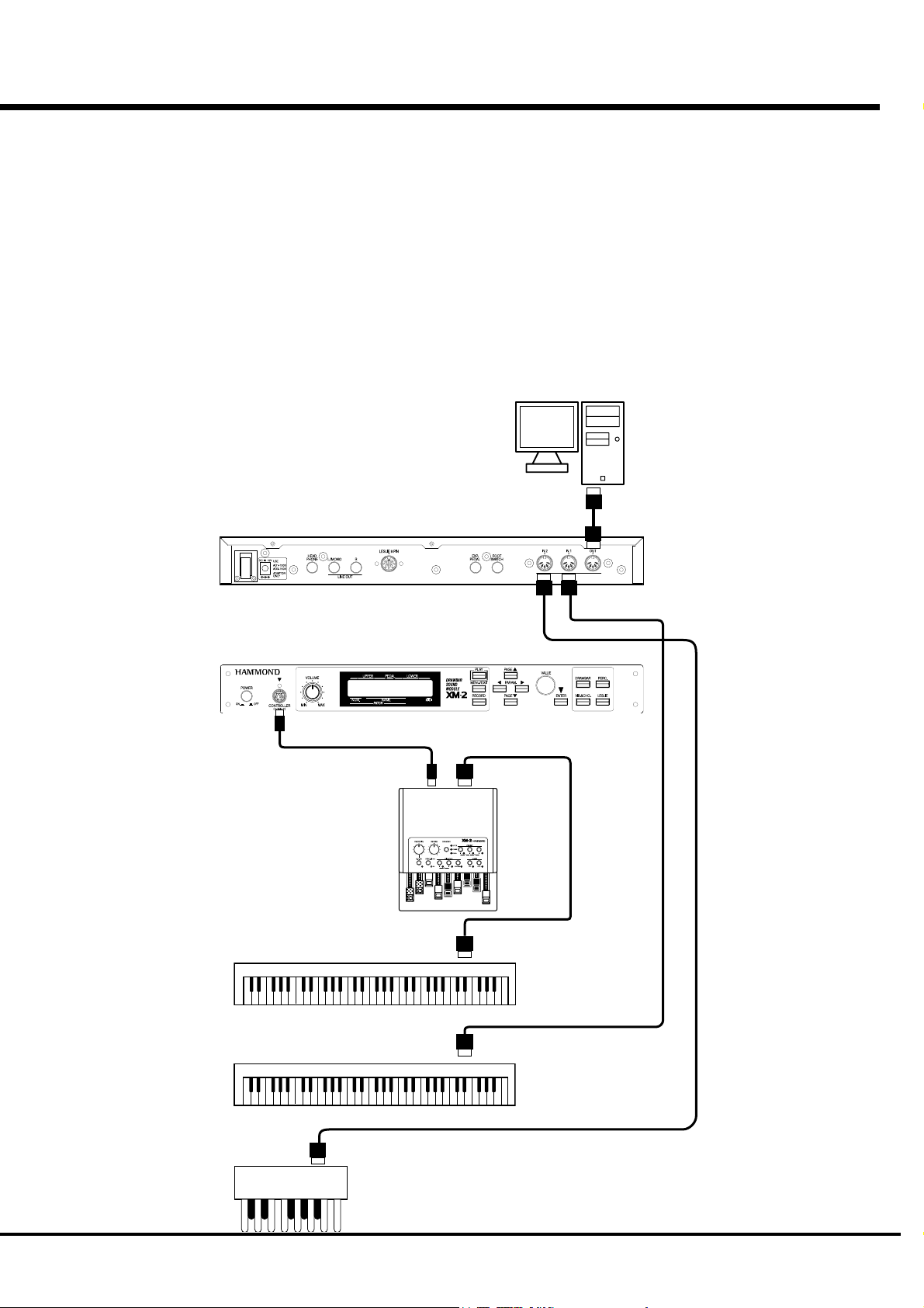
CONNECTION USING MULTIPLE MIDI
KEYBOARDS AND THE XMc-2
Using the Drawbar Controller XMc-2 allows you not only to change the Draw-
bar Registration at hand, but also to easily build the double or triple manual
systems using the built-in MIDI IN terminal of the XMc-2.
Set each MIDI Keyboard to send a single channel. (The channel number does
not matter.)
Call out “2/3KBD via XMc” by the MIDI Template (P. 68) of this unit.
This example of connection allows you to record into an external sequencer.
MIDI Sequencer,
Computer etc.
(optional)
17
TO XM-2
MIDI Keyboard (for UPPER)
MIDI OUT
MIDI Keyboard (for LOWER)
MIDI OUT
MIDI OUT
MIDI Pedalboard
MIDI IN
Hook-Up
Page 18
18
CONNECTION OF LESLIE SPEAKER
This unit has an 8-pin Leslie Connector which can directly connect the Leslie
Speaker.
Be sure to turn OFF the power before you connect to the Leslie Speaker.
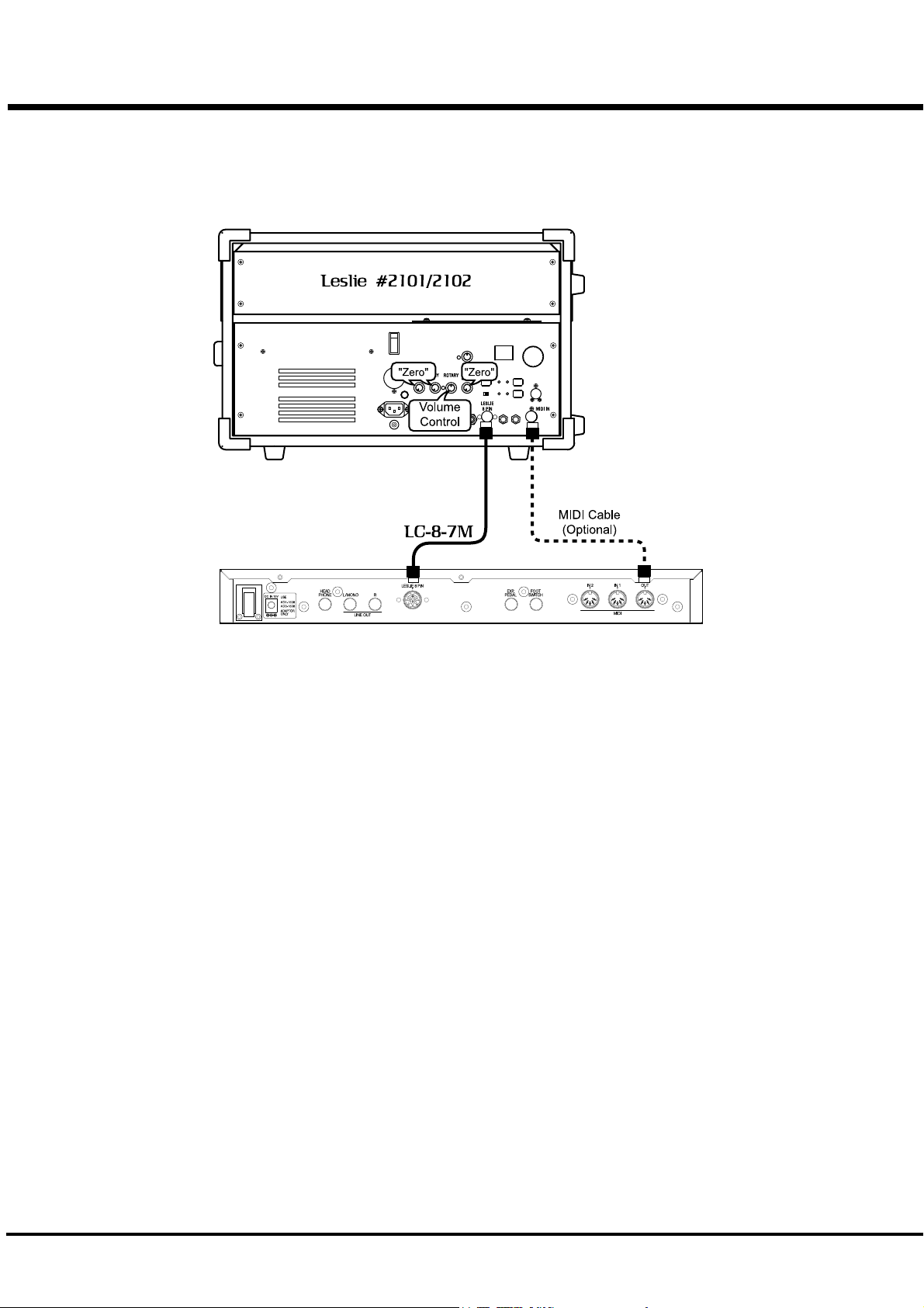
BASIC CONNECTION OF THE LESLIE
SPEAKER
Connect the Leslie Speakers #2101, 2102 and the Leslie 8-pin terminal by use of the exclusive
8-pin Leslie Cable LC-7-8M(= optional, to be separately purchased).
NOTE: The Leslie terminal on this unit has 8 pins. For connecting a 11-pin Leslie Speakers, you
need a Leslie Adaptor XLD-811 (= optional, to be separately purchased).
The volume of the Leslie Speakers #2101, 2102 is adjusted by the Rotary knob. Set the Sta-
tionary knob at Minimum. The sound circuit on this unit is specified for a single channel.
Refer to the Leslie Speaker manual as well to make sure.
MIDI CONTROL OF LESLIE SPEAKER
For MIDI-controlling the parameters (=fine adjustment of the Rotary speed, rise time, etc.) on
the Leslie #2101, 2102:
1. Connect the MIDI OUT of this unit and the MIDI IN on the Leslie Speaker by the MIDI cable.
2. Set the MIDI channel - UPPER of this unit and the MIDI channel of the Leslie Speaker to the
same channel. (P. 69 #11)
3. Set the MIDI - Leslie Parameter of this unit at “21”. (P. 69 #8)
*#1 :/Owner’s Manual
Page 19

TURN ON AND PLAY
19
*#1 :/ Owner’s Manual
Page 20
20
TURN ON THE POWER
HOW TO TURN THE POWER ON
After the connection is completed, turn on the power in the following order: If you do not follow this
order, it may cause malfunctions or damages to the speakers etc.
STEPS TO TAKE
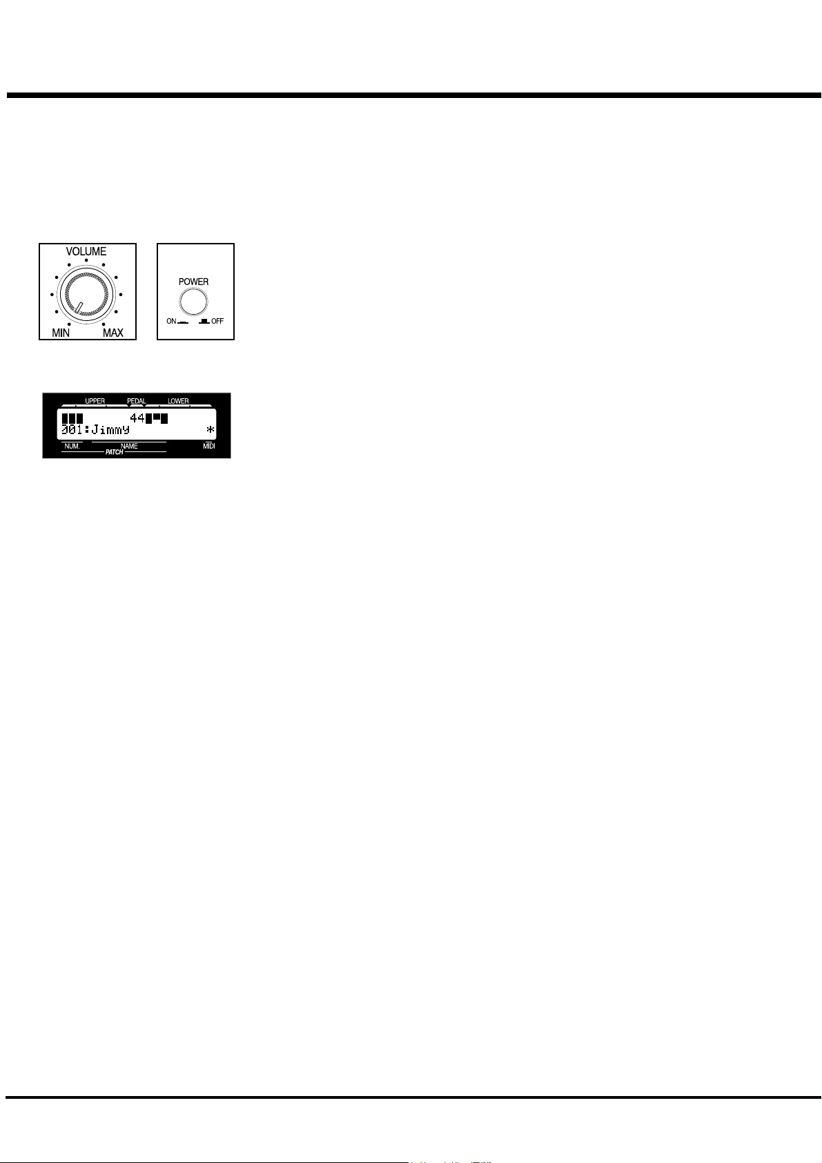
1. Before turning the unit ON, make sure that the [VOLUME] knob of this unit is at MIN.
2. Turn the [POWER] switch ON. In the display, the title and then the PLAY mode appears. (See
the illustration.)
It does not immediately start up after turning the power on because of circuit protec-
tion.
3. Turn on the power of the connected amplifier etc.
4. Turn the [VOLUME] knob for fine adjustment.
5. Adjust the volume of the amplifier etc.
You can adjust the volume more easily if you use the demonstration play.
When you turn off the power, do the above procedure backwards. Turn OFF the ampli-
fier etc. first.
BACK-UP
This unit memorizes the status of the settings immediately before it is turned off. For this reason, the
settings when the unit is powered up is the same as they were just before the unit was shut off. This
is called BACK-UP.
RESET TO THE FACTORY SETTINGS
To return all settings on this unit to the original Factory Settings, do the following:
STEPS TO TAKE
1. Turn OFF the power on this unit.
2. Turn the power ON, holding down the [RECORD] button.
3. Keep pressing the [RECORD] button until “Loading Default” appears in the display.
4. The procedure is completed when the PLAY mode appears.
*#1 :/Owner’s Manual
Page 21
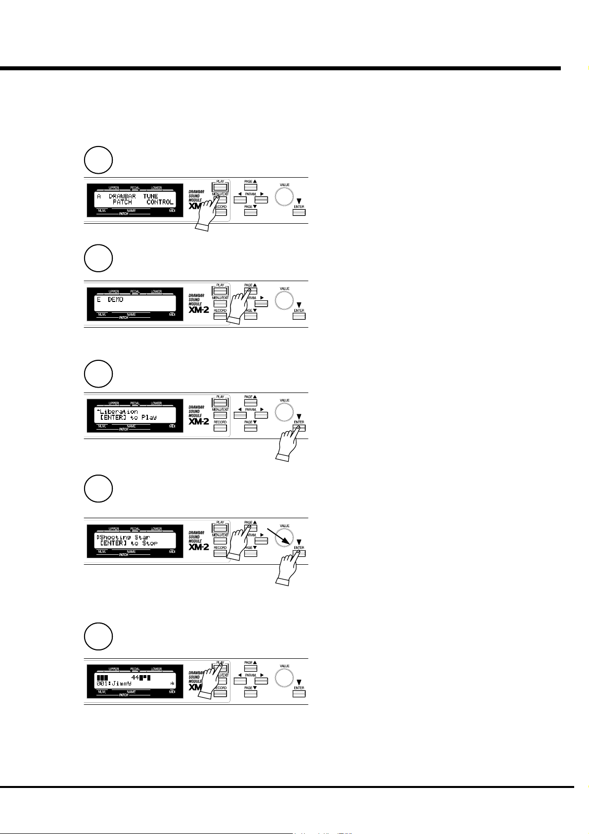
STEPS
1
2
LISTEN TO THE DEMONSTRATION
Demonstration Plays are built in for introducing the features, sounds, etc. of
this unit.
Touch the [MENU/EXIT] button and display the menu.
Touch the [PAGE] button and go to Page E.
21
3
4
5
Touch the [ENTER] button.
The Demo mode appears.
Select the tune you want to listen to by touching the
[PAGE] button.
The play starts when you touch the [ENTER] button.
NOTE: When the tune ends, the next one automati-
cally starts.
For selecting another tune while playing, touch the [EN-
TER] button again. (The play stops.)
To stop the Demo Play, touch either the [MENU/EXIT]
or [PLAY] button.
NOTE: Demo Plays do not affect the existing set-
tings.
Turn On and Play
Page 22
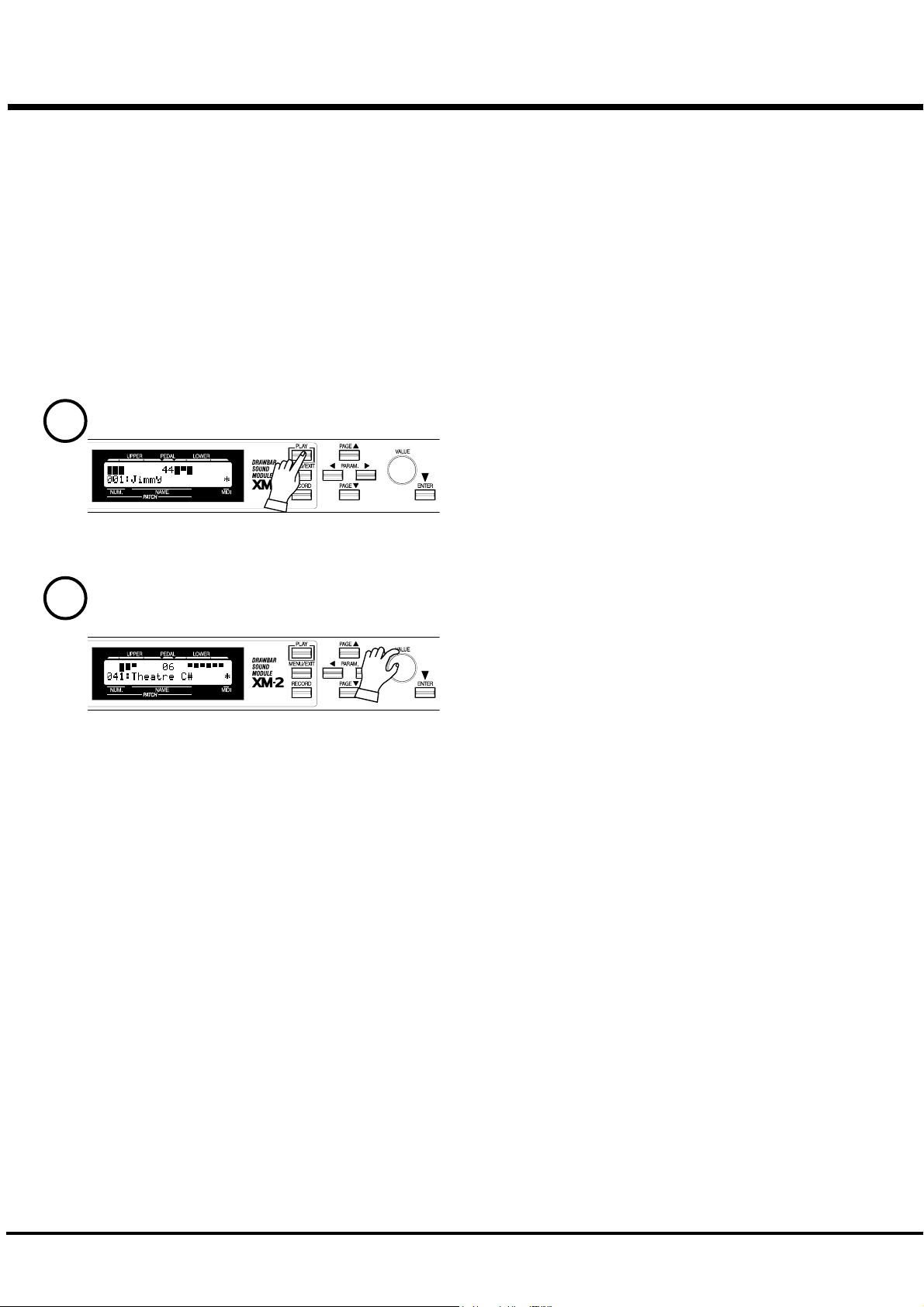
22
This unit memorizes various settings up to 128 [PATCHES]. For your imme-
diate play after purchasing this unit, the factory settings are recorded in the
patches 001 to 120.
PLAY BY THE PATCH
HOW TO CALL OUT THE PATCHES
EXAMPLE: Select 041.
1
2
GO TO THE PLAY MODE
If the present mode is not PLAY, touch [PLAY] and go to the
PLAY mode.
SELECT THE PATCH NUMBER
Select Patch No. 041 by the [VALUE] knob.
Call out various patches and play.
When you call out a patch, not only does the Drawbar registra-
tion of each part change but also the effects such as Leslie and
Reverb also change.
NOTE: You can set the type of parameter you call out. (P.
52 #2 to 8)
WHAT IS “PART” ?
*#1 :/Owner’s Manual
A [PART] is like a player in a band or in an orchestra.
Like an organ with 3 manuals can produce 3 different sounds, this unit also can produce 3 different
parts, Upper, Lower, and Pedal, because it has these 3 different parts.
NOTE: The function that makes it possible to use multiple sounds is called [Multi-Timbre].
Page 23
You can play more expressively if you operate the controller while playing.
Let us explain in this page about the controller generally used in electronic
musical instruments. (About the unique HAMMOND Controller, let us ex-
plain in the next page.)
PITCH BEND
PLAY WITH THE CONTROLLERS
You can change the pitch while playing, by receiving the Pitch Bend informa-
tion.
NOTE: You can adjust the amount of the pitch change by the Pitch Bend
information. (P. 54 #1 to 4)
23
This figure shows an example: XK-1.
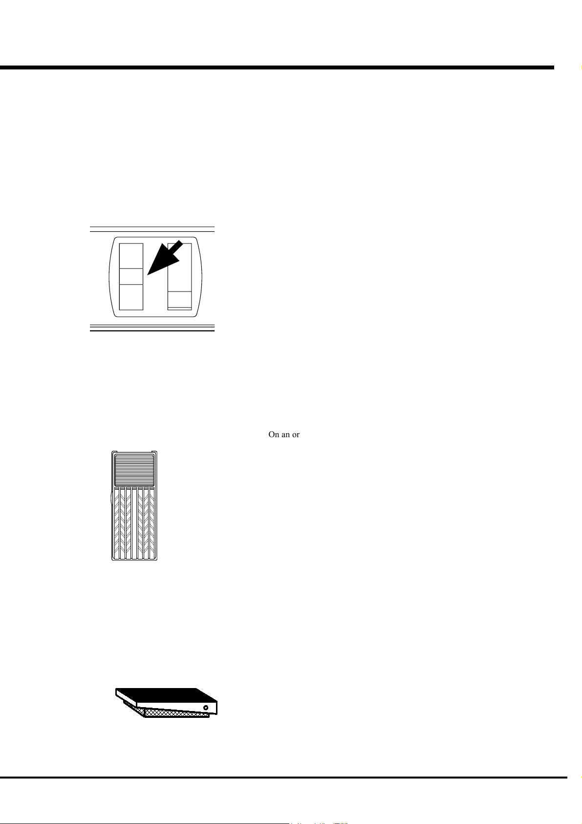
EXPRESSION PEDAL
This figure shows V-20R ( = optional, to be
separately purchased).
On an organ, generally not like on the piano, the velocity, i.e. touch on the keys,
does not give any dynamics.
However, if you connect an expression pedal ( = optional) to this unit, or receive
the expression information from the MIDI, you can change the volume and give
expression to your play.
The volume of the Expression Pedal gets maximum when fully depressed on the
toe-side and gets minimum when fully returned on the heel-side.
NOTE: Set this unit to match the model of your expression pedal. (P. 56
#13)
FOOT SWITCH
This figure shows FS-9H ( = optional, to be
separately purchased).
This is used for controlling various switches by foot instead of doing it by hand.
In the default settings, “Leslie Fast” is assigned here.
NOTE: You can change the assignment of the foot switch. (P. 57 #19 to 20)
Turn On and Play
Page 24
24
CREATE YOUR OWN SOUNDS
Let us here explain how to create the unique HAMMOND sounds such as Drawbars,
Percussion sounds and the sounds obtained by using the Vibrato or Leslie effects.
The example here is after a MIDI Keyboard (set for MIDI Channel 1) is connected to
the MIDI IN 1 terminal of this unit (immediately after delivery from your dealer).
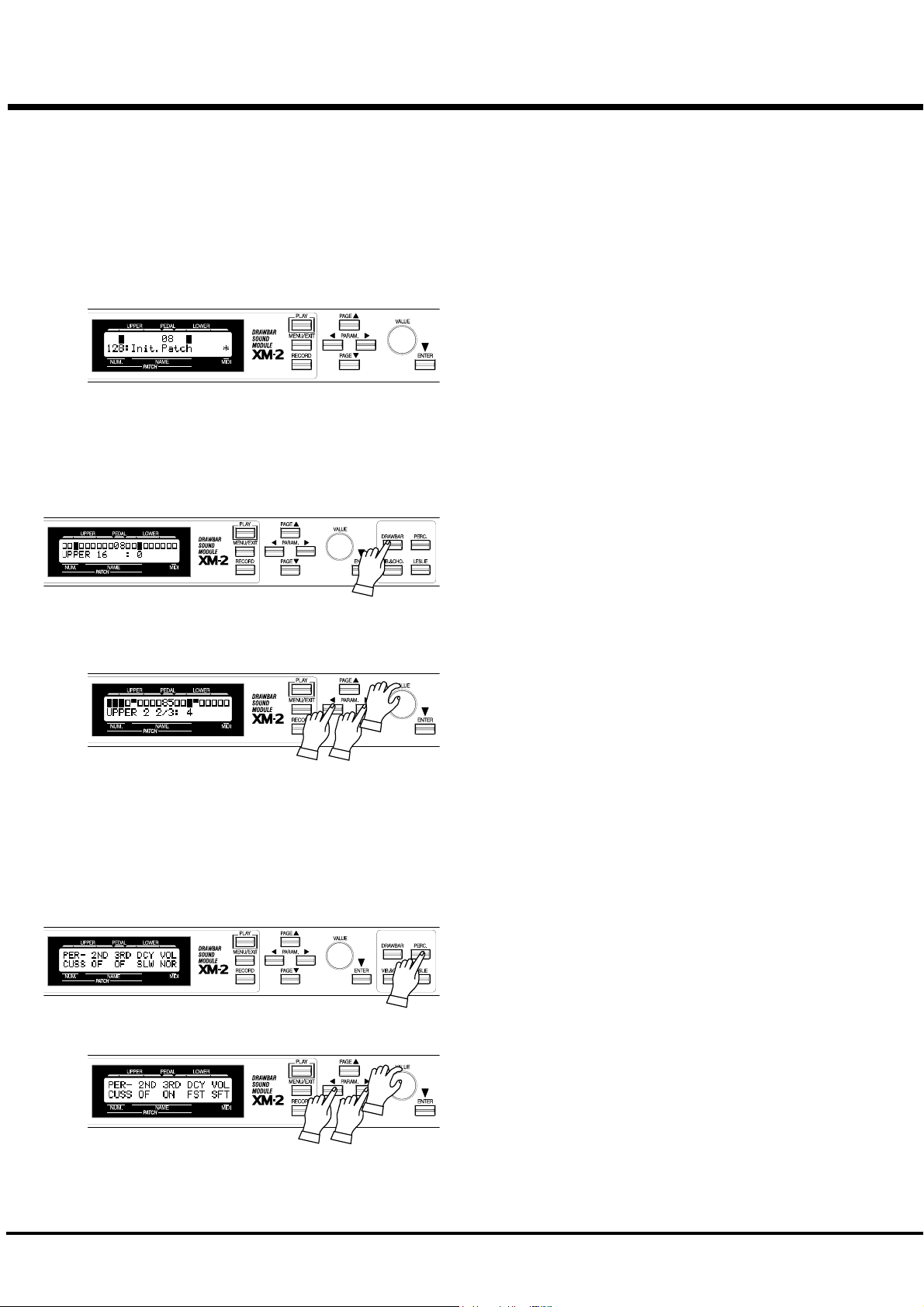
SELECT PATCH 128.
Call out Patch Number 128. The default setting of this Patch is the
simplest of all, so it is best suited for creating new sounds.
MAKE THE DRAWBAR REGISTRATION
Touch the [DRAWBAR] button. The display turns into the Drawbar
Registration (how far the bars are drawn) mode.
In this mode, the basic sounds using the Drawbars are created.
Adjust the volume of each footage in the range of the displayed “UP-
PER”, while touching the keys.
The volume gets loud when the value of each footage (each digit of
Drawbar Registration) increases. It gets quieter when the value gets
smaller. Basically, the pitch gets higher from left to right.
Select the footage by the [PARAM] button, and change the value by
the [VALUE] knob. Operate the other parameters in the same way.
The most frequently used registrations are 3 fully drawn left-side
bars and all 9 fully drawn bars.
NOTE: You can change the characters of the Drawbars. (P. 50 )
ADD PERCUSSION
*#1 :/Owner’s Manual
The “Percussion” here is not the ordinary percussion instrument but
that of decaying sounds that adds lively and articulate sounds. Mix
the sounds with the Drawbar sounds whenever you want.
Touch the [PERC] button. The display turns into the PERCUSSION
mode.
Turn ON and OFF each value of “2ND” and “3RD” of the parameter
by the [PARAM] button and the [VALUE] knob. The decay sounds
of an octave higher “DO” (the second harmonics) and “SO” (the third
harmonics) are added to the note on the keyboard.
The decay speed gets faster if you change “DCY” from SLW to FST.
The Percussion volume goes down if you change “VOL” from NOR
to SFT.
NOTE: You can fine-adjust the percussion volume etc. (P. 61)
Page 25
ADD EFFECTS
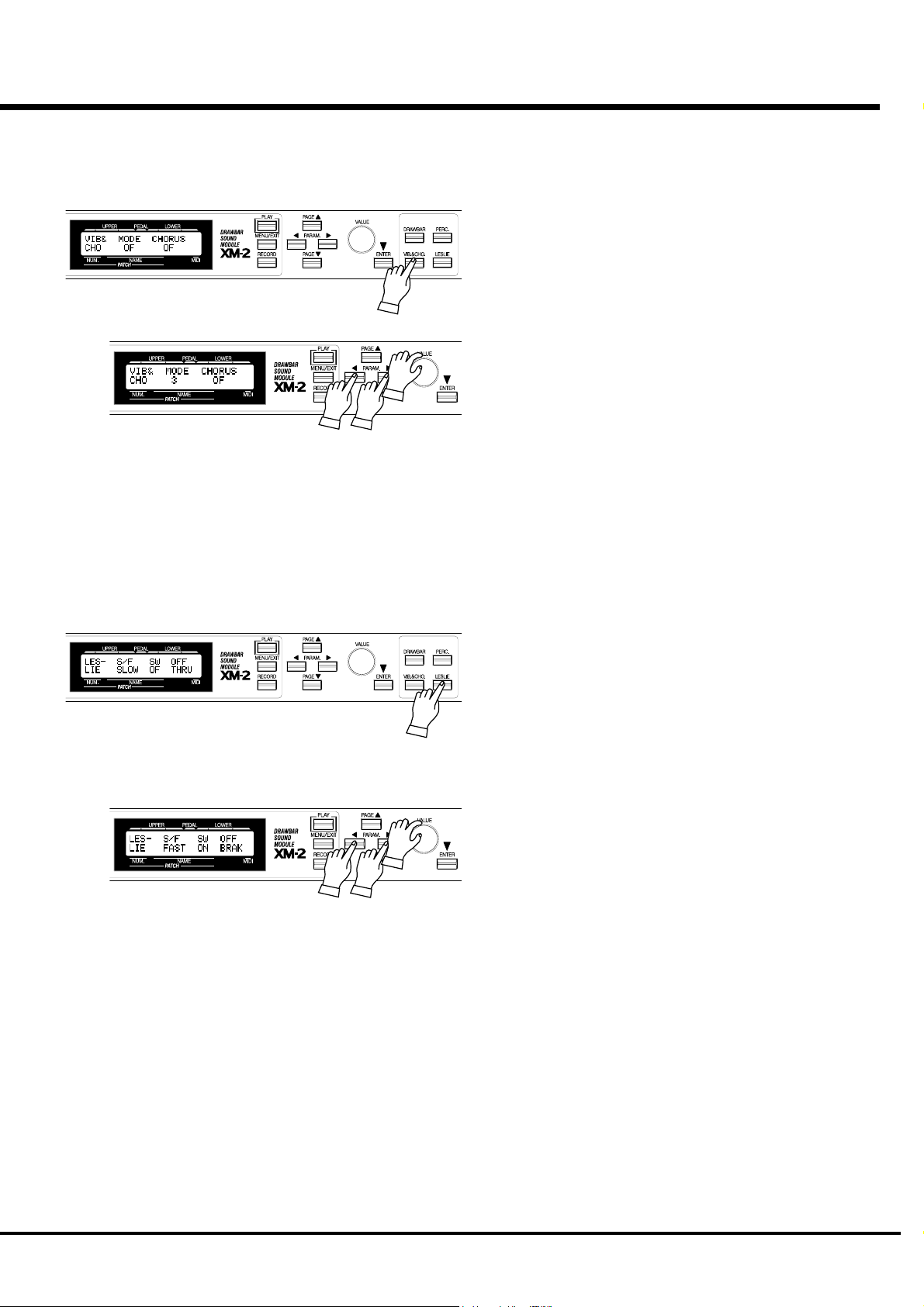
VIBRATO AND CHORUS
25
Warmth can be added to the sound by slightly changing the Drawbar
pitch in a certain cycle.
Touch the [VIB&CHO] button. The display changes to Vibrato and
Chorus mode.
“MODE”
This sets the depth of the Vibrato effect. At OF no effect is added.
As the value gets larger from 1 to 3, the effect gets deeper.
“CHORUS”
Vibrato sound is mixed to the original tone, and thickness is added to
the sound when you turn this on.
LESLIE
This gives the effects of a live performance feelings by the feeling of
turning rotors.
Touch the [LESLIE] button. The display changes to the Leslie mode.
“SW”
Turn this ON to get the Leslie effects.
“S/F”
This switches the Rotor speed to SLOW or FAST (2 steps). The most
popular style is to play at SLOW basically and then to change to
FAST only at the climax.
“OFF”
This sets the action when the value of the parameter “SW” of the
Leslie effect is OF. BRAK stands for Brake. (The Rotor gradually
slows down and then finally stops.) THRU stands for Through. (The
Leslie effect is bypassed.)
NOTE: These parameters are used for controlling, in the case
Leslie speakers are connected externally.
NOTE: Fine settings are possible for the turning speed of the
built-in Leslie effects etc.
In this chapter we have explained the settings you can make from the panel buttons.
Let us explain in the next page about the Overdrive and Reverb; elements for creating the
HAMMOND ORGAN sounds.
Turn On and Play
Page 26
26
RECORD TO THE PATCH
The settings you have made so far can be recorded or memorized to your desired
Patches.
You can also freely rewrite the built-in Patches when delivered from the factory.
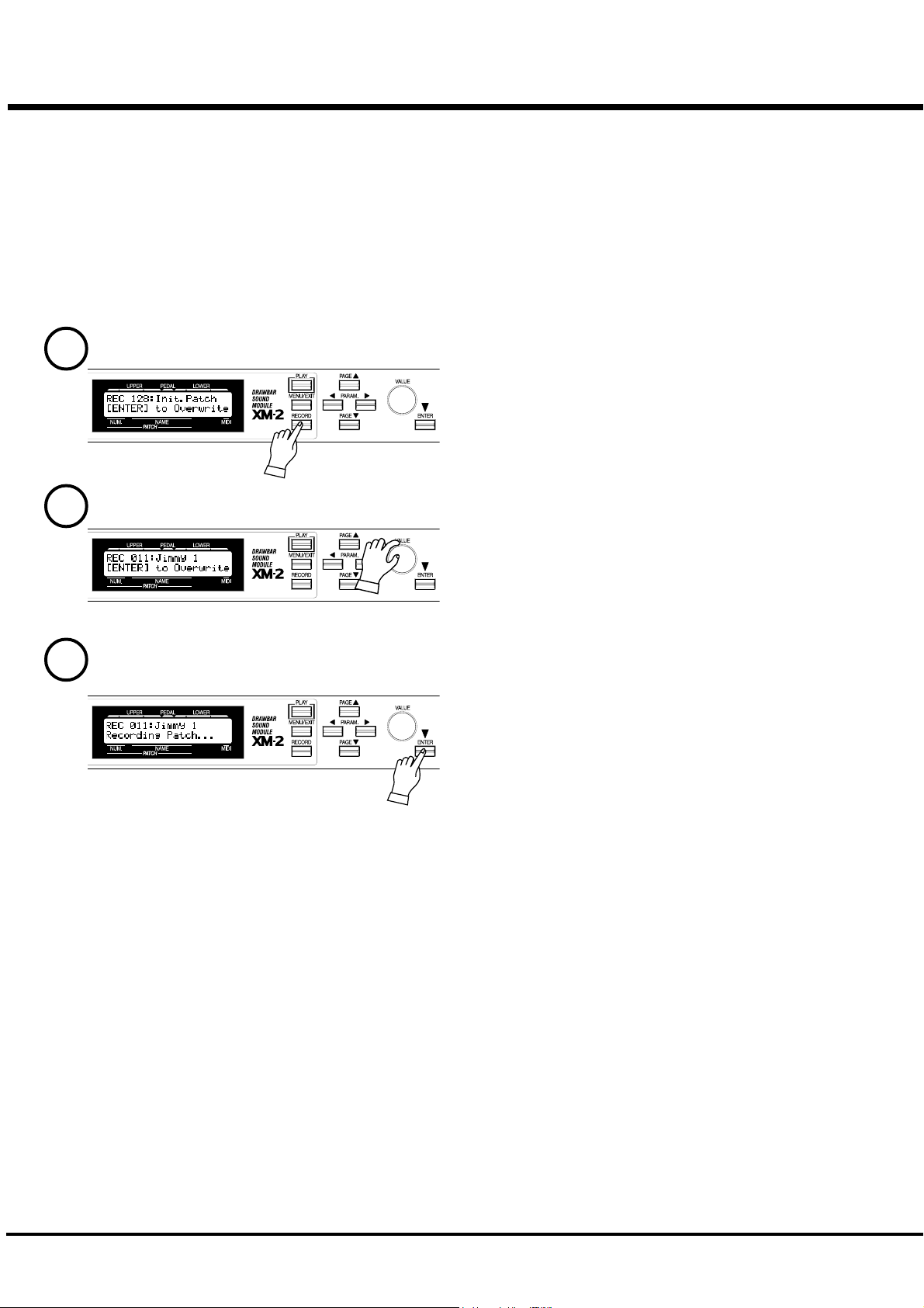
EXAMPLE: RECORD INTO “011”
1
2
Touch the [RECORD] button. The Record mode appears.
Select the Patch Number (011 in this example) to record to by the
[VALUE] knob.
3
Touch the [ENTER] button. The Patch is decided and the following
is displayed in the mode for certain seconds:
Recording Patch...
When the recording is completed, the display returns to the immedi-
ate previous mode.
NOTE: The recorded Patch data are not lost even after the
power is turned off.
*#1 :/Owner’s Manual
Page 27

SETTING UP
27
*#1 :/Owner’s Manual
Page 28

28
SOUND ENGINE STRUCTURE
SYSTEM STRUCTURE OF XM-2
*#1 :/Owner’s Manual
Page 29

To fully enjoy playing this module, please read the following section of
this manual.
See the illustrated System Structure of your keyboard on the left page.
TONE-WHEELS
The sound source or “engine” of the Hammond Organ is the Tone-wheels. They
are like the strings and pick-ups on the electric guitar. While running, each of the
96 digital Tone-wheels keeps oscillating at a different pitch/frequency.
KEYS
Each of the sound signals made by the 96 digital Tone-wheels is switched at each
key. Each signal corresponding with each pitch and harmonic is distributed to
each key (as an example, 9 signals for the manual keyboard). The keys are switched
on and off by depressing and releasing the keys.
DRAWBARS
The Drawbars prepare the basic sounds. Each bar adjusts the value of a harmonic
(as an example, 9 harmonics for the manual keyboard).
PERCUSSION
The Percussion makes the decay sound, synchronizing with the key touch of the
UPPER part.
29
TONE-WHEEL SET
The Tone-wheel Sets are divided into the
Manual Keyboard and the Pedal Part. This is to
give the Pedal Part the Decay (= the sound
gradually fading out while pressing the key) or
Sustain Effect. (= the sound gradually fading
out after the key is released).
HARMONICS
Harmonic is a pitch of a different ratio to a cer-
tain pitch; for example, the one octave higher
C to the middle C. The more Harmonics, the
brighter and richer the sound.
VIBRATO/CHORUS
Vibrato gives vibration to the pitch. By mixing the vibrato sound with the funda-
mental sound, Chorus effect is obtained.
NOTE: On this module, the scanner circuit of the B-3/C-3 is simulated, which gives
more effects than the changes of the pitch.
OVERDRIVE
Overdrive adds the fuzzy, raspy, “dirty” sound created by the vacuum tubes of a
tube-style Leslie Speaker when its volume is pushed past its sound limit.
The PEDAL Part however, is designed not to pass through the Vibrato/Chorus or
the Overdrive in order to obtain the clear Bass-line.
EQUALIZER, LESLIE and REVERB
The sound that comes out of the output terminal after passing the special effects:
the Equalizer (for tone regulation), the Leslie (for the rotating speaker effects)
and the Reverb (for resonance). (The built-in Leslie Effect cannot be heard through
the Leslie 8-pin terminal.)
NOTE: The built-in Leslie Effect is designed to smoothly simulate the rotations of
the two rotors.
Setting Up
Page 30

30
HOW TO USE THE PANEL BUTTONS
The “Panel Buttons” are the 4 buttons for operating the same functions as those of the
knobs and tablets on the panel of the HAMMOND ORGAN. The basic sounds of the
HAMMOND ORGAN are created by the Panel Buttons, the [PARAM] button, and
the [VALUE] knob.
EXAMPLE: Set Upper 8' of Drawbar registration at 5.
STEPS TO TAKE
1
Touch the [DRAWB] button.
The display turns into Drawbar Registration mode.
2
3
4
Touch the [PARAM] button and move the blinking cursor
(value) to UPPER 8'.
Set the value at 5 by the [VALUE] knob.
Touch [PLAY] to return to the PLAY mode.
*#1 :/Owner’s Manual
Page 31

DRAWBAR (DRAWBAR registration)
This mode is for setting the Drawbar Registration to create the basic sounds.
To locate this mode:
Touch the [DRAWBAR] button.
The first line in the display shows the Drawbar Registration of each part, from left to right,
UPPER, PEDAL, LOWER. The parts UPPER and LOWER are displayed by bar graphs, and
the PEDAL part by figures(numerals). The bottom line shows the currently selected length
of bars (feet) and the values (levels).
You can change the value by selecting the length (footage) by the [PARAM] button and
turning the [VALUE] knob.
31
Setting Up
Page 32

32
DRAWBARS™
The 9 Drawbars (only 2 for the PEDAL parts) on the HAMMOND ORGAN are used to create
different sounds. On each Drawbar the numbers 1 to 8 are marked. When the Drawbar is pushed
back until you can not see the number, the Drawbar does not give any sound. When you pull out
the Drawbar to the full extent, the volume of the Drawbar is at its loudest setting.
This unit has no physical Drawbars, but you can do the same things as on the real organ by
operating the displayed Drawbar Registrations.
The pitch of each Drawbar is as shown above, when the middle C is depressed. The footage
marked (') on each Drawbar is originated from the length of the pipes of the pipe organ.
The numbers 1 - 8 on each Drawbar indicate the volume of the sound to be produced as well as
the guide to simply set the Drawbar.
For example, when you blow clarinet, the internal air vibrates, and the fundamental (8') and the
third harmonic (2 2/3') plus the fifth harmonic (1 3/5') come out at the same time. On this mod-
ule, if you pull out 3 Drawbars, you can get the clarinet sound. If you pull out the right hand side
one of the 3 Drawbars a little longer and the left hand side one a little shorter, the element/
component of the high pitch increases and a hard sound comes out. If you pull out the left hand
one a little longer, on the contrary, the sound gets mellow.
Thus, you can make delicate changes to the sound, depending on the flow of the tune/music or
your choice/preference, by fully utilizing the Drawbars.
NOTE: You can change the characters of the Drawbars. (P. 50)
*#1 :/Owner’s Manual
Page 33

WHITE DRAWBARS
BLACK DRAWBARS
33
In each Drawbar set, the white Drawbar (8') on the left end makes the basic/
fundamental sound. The other white Drawbars get higher by the octave to
the right.
The sounds of the black Drawbars, too, play important roles in building rich
tones. Their pitches are fifth and third to the fundamental. They contain the
elements of all different harmonics of such as the sweet and soft horn, mel-
low strings and so on.
BROWN DRAWBARS
PEDAL DRAWBARS
The two brown Drawbars on the far left have the role to give depth and
richness to the sound. The left 16' is one (1) octave lower than the 8,' and 5
1/3' is the third harmonic of the 16' fundamental.
Normally, the tones are built on the 8' fundamental, but, if you want to add
depth to the tone or to expand the playing range on the manual by one (1)
octave, the tones are built on the 16' fundamental.
The Pedal Part is for playing the bass line usually, using the only two Draw-
bars -16' and 8'. Others are not used.
The first Pedal Drawbar produces a tone at 16' pitch for a deep foundation
bass, while the second Pedal Drawbar produces a tone at 8' pitch, or one
octave higher.
The registration of the Pedal Part is displayed in the center of the display, the
left one is 16', and the right one is 8'.
Setting Up
Page 34

34
DRAWBAR REGISTRATION PATTERNS
The Drawbar Registrations are usually represented by the numbers (footage values) of the 9 Drawbars.
The following are the typical 4 patterns of registrations. You will see the instrument names together with
the numerical registrations on the right hand side of each pattern.
The easiest way for you to obtain the basic tones you want is to remember the typical patterns of the
combined 9 Drawbars.
Flute family (2 step pattern)
Accompaniment Flute 8' I
Accompaniment Flute 8' II
Accompaniment Flute 8' III
Chorus of Flutes 16'
Orchestral Flute 8'
Piccolo 2'
Stopped Flute 8'
Tibia 8'
Tibia 4'
Tibia (Theater) 16'
Wooden Open Flute 8'
00 8460 000
00 3220 000
00 8600 000
80 8605 002
00 3831 000
00 0006 003
00 5020 000
00 7030 000
00 0700 030
80 8605 004
00 8840 000
Reed family (triangle pattern)
Bassoon 16'
Clarinet 8'
English Horn 8'
Flugel Horn 8'
French Horn
Kinura 8'
Oboe 8'
Trombone 8'
Trumpet 8'
Tuba Sonora 8'
Vox Humana 8'
44 7000 000
00 6070 540
00 3682 210
00 5777 530
00 7654 321
00 0172 786
00 4764 210
01 8777 530
00 6788 650
02 7788 640
00 4720 123
*#1 :/Owner’s Manual
Page 35

Diapason family (check mark pattern)
Accomp. Diapason 8'
Chorus Diapason 8'
Diapason 8'
Echo Diapason 8'
Harmonic Diapason 16'
Harmonic Diapason 8'
Harmonic Diapason 4'
Horn Diapason 8'
Open Diapason 8'
Solo Diapason
Wood Diapason 8'
35
00 8874 210
00 8686 310
00 7785 321
00 4434 210
85 8524 100
00 8877 760
00 0606 045
00 8887 480
01 8866 430
01 8855 331
00 7754 321
String family (bow pattern)
Cello 8'
Dulciana 8'
Gamba 8' I
Gemshorn 8'
Orchestral String 8'
Salicional 8'
Solo Viola 8'
Solo Violin 8'
Viola da Gamba 8'
Violina 4'
Violone 16
00 3564 534
00 7770 000
00 3484 443
00 4741 321
00 1464 321
00 2453 321
00 2474 341
00 3654 324
00 2465 432
00 0103 064
26 3431 000
Setting Up
Page 36

36
PERC (PERCussion)
The Percussion attack sound is a Hammond exclusive.
Percussion is usually used with the Drawbar sound.
To locate this mode:
Touch the [PERC.] button.
2ND (Second)
The second harmonic or 4' Drawbar decay is added to the UPPER Part.
To use this, set the value “ON”.
3RD (Third)
The third harmonic or 2 2/3' Drawbar decay is added to the UPPER Part. By mixing it with
the Drawbars, a distinctive sound is obtained.
To use this, set the value “ON”.
DECAY
The piano sound gradually goes out even
if you keep the key down. This is called “de-
cay”. The violin on the contrary, keeps
sounding at a certain volume. This is called
“sustain”.
DCY (DeCaY)
This sets the decay time for the Percussion.
It is effective if you use this to play with a clear-cut rhythm in an up-tempo piece.
Select “SLW” (slow) or “FST” (fast).
VOL (VOLume)
This sets the volume of Percussion.
Select “NOR” (normal) or “SFT” (soft).
NOTE: You can fine-adjust Percussion. (P. 61)
NOTE
DRAWBAR CANCEL
When either the “2ND” or “3RD” is ON, 1' in the Upper Part Drawbars does not produce
a sound. This is the same action as on the B-3/C-3.
NOTE: You can set to play 1' Drawbar, while Percussion is ON. (P. 61 #8)
*#1 :/Owner’s Manual
Page 37

VIB & CHO (VIBrato and CHOrus)
VIBRATO adds warmth to the tone, by slightly changing the Drawbar pitch at a
certain speed.
You can also add richness to the sound by mixing the Vibrato sound with the funda-
mental (= Chorus Effect).
To locate this mode:
Touch the [VIB.&CHO.] button.
MODE
This sets the depth of Vibrato effect.
No effect at OF. The larger the value gets (1 to 3), the effect gets deeper.
37
CHORUS
This is for switching Vibrato and Chorus effects.
Turn this ON to get the Chorus effect.
NOTE: You can make fine settings for Vibrato and Chorus effects. (P. 65 #4 to 12)
Setting Up
Page 38

38
LESLIE
LESLIE EFFECT is the simulated sound of rotating speakers.
If you connect the real Leslie speakers to this module, it controls those (speakers).
To locate this mode:
Touch the [LESLIE] button.
SW
Turn this ON to turn the Rotor. The sound is sent out from the Rotary Channel.
S/F
Select the Rotor speed from either SLOW or FAST.
OFF
This sets the operation when the SW is OF. Select either BRAK or THRU. BRAK stands
for Brake. (The Rotor gradually slows down and finally stops.) THRU stands for Through.
(The Leslie effects are bypassed, and the sounds are sent out from the stationary chan-
nel.)
NOTE: You can not control the Brake or Through on external Leslie Speakers.
NOTE: You can fine-set the LESLIE effect, i.e. the Leslie speed. (P. 62)
In the Leslie speakers, generally an amplifier and two rotors are
incorporated, i.e. the “Horn Rotor” responsible for the treble and
the “Bass Rotor” for the bass.
Each rotor has a speaker or speakers and a motor for controlling
the speed to give the unique tremolo sound gained by the Doppler
effect.
There are also models that have not only the rotors but also sta-
tionary speakers - switchable.
The circuit to send the sound to the rotor is called “Rotary Chan-
nel” and that to the stationary speaker is called “Stationary Chan-
nel”.
The built-in Leslie Effect simulates them and you can get the best
effect when connected to a stereophonic amplifier and speaker
system.
PARAMETERS AND STATUS
Parameter
S/F SW
Fast On Brak
Fast On Thru
Slow On Brak
Slow On Thru
Fast Off Brak
Slow Off Brak
Fast Off Thru
Slow Off Thru
OFF
MODE
WHAT IS THE LESLIE EFFECT?
State
External
Leslie
Speaker
Fast Through
Slow Through
Internal
Leslie Effect
Fast
Slow
Brake
*#1 :/Owner’s Manual
Page 39

The settings you have made can be recorded into the Patches.
NAME THE PATCH
Go to the MENU.
1
Go to PAGE A.
2
PATCH
39
Touch the [MENU/EXIT] button.
The MENU mode will be displayed.
If the PAGE A is not displayed, touch the [PAGE] button and
go to PAGE A.
Go to the PATCH function mode.
3
Input the NAME.
4
Select the PATCH by using the [PARAM] button. Touch the
[ENTER] button and go to the PATCH function mode.
You can store names using up to 10 letters.
[PARAM] Button: moves the cursor.
[VALUE] Knob: selects letters.
You can use all the Alphabet letters large and small, signs/
symbols and digits.
The name input here is only temporary. Do the recording op-
eration to save it, as explained on the next page.
Setting Up
Page 40

40
RECORD A NEW PATCH
EXAMPLE: RECORD INTO “011”.
Touch the [RECORD] button.
1
Touch the [RECORD] button. The [RECORD] mode appears on
the display.
Select the Patch number.
2
Touch the [ENTER] button.
3
Select by the [VALUE] knob the patch number you wish to record
in. (No. 011 in this example)
Touch the [ENTER] button.
The Patch will be decided and the following message will appear
in the display for a few seconds:
Recording Patch ...
When the recording is completed, the display returns to the pre-
vious one.
NOTE: The recorded Patch data is not lost even after the power is
turned off.
*#1 :/Owner’s Manual
Page 41

DISPLAY AND ITS
41
OPERATION
*#1 :/Owner’s Manual
Page 42

42
PLAY MODE
The PLAY MODE is the basic display for all the operations. The necessary informa-
tion for the normal play will be displayed.
There are two types of PLAY MODE screens to display the Drawbar Registration.
One is by showing the length of the Drawbars and the other by digits.
To locate this mode:
1. The PLAY mode will be displayed immediately after the power is turned ON and the
start-up steps are completed.
2. Touch the [PLAY] button if the displayed mode is wrong.
HOW TO READ THE DISPLAY
Drawbar Registration
UPPER Part/ PEDAL Part/ LOWER Part
BAR display
Patch Number :
Name
These two PLAY mode displays (= the bar dis-
play and the digital display) will be switched ev-
ery time you touch the [PLAY] button.
In the bar display, the Patch name is shown but
another Patch, if assigned to the LOWER Part is
not shown.
Also, the MIDI IN Note Information is displayed.
Sounding on MIDI Note
Message
DIGITAL display
Number on LOWER & PEDAL Part/
Number on UPPER Part
The Patch name is not shown in the digital mode
display, but you can see the Preset Number of the
LOWER Part.
*#1 :/Owner’s Manual
Page 43

PANEL BUTTON MODE
The Panel Button mode is used for controlling the same functions as the knobs and
tabs do on the HAMMOND ORGAN.
By using the Panel Buttons, the [PARAM] buttons, and the [VALUE] knobs, you can
create the basic sounds of the HAMMOND ORGAN.
To locate this mode:
Touch one of the Panel Buttons you want to set; [DRAWBAR], [PERC], [VIB&CHO], and
[LESLIE].
HOW TO READ THE DISPLAY
Drawbar registration
UPPER Part/ PEDAL Part/ LOWER Part
Drawbar
Registration
43
mode
Selecting FOOTAGE: LEVEL
PARAMETER
Percussion
mode
VALUE
CURSOR
(Flashing VALUE)
BUTTON OPERATION IN THIS MODE
These buttons are used to move the CURSOR right
Returns to the PLAY mode.
or left for selecting the PARAMETER to change.
CURSOR
In the display window of this keyboard, the
CURSOR is displayed in the flashing style,
while the most popular indicator- cursor
used on the PC, the mobo, etc. is in the
shape of an arrow, a square or an I-shape.
The CURSOR increases or decreases the
value of the Parameter.
Display And Its Operation
Page 44

44
The MENU mode is the path for each function.
MENU MODE
To locate this mode:
Touch the [MENU/EXIT] button.
There are several pages which contain many various FUNCTION displays. Move from
page to page and find the item where you want to go, select item by [PARAM] button,
and touch the [ENTER] button to see the desired display.
HOW TO READ THE DISPLAY
FUNCTION ITEM
PAGE
(If none, blank.)
BUTTON OPERATION IN THIS MENU
Moves from a page to another.
Returns to the PLAY mode.
Select the FUNCTION ITEM.
*#1 :/Owner’s Manual
Enter each FUNCTION MODE.
Page 45

FUNCTION MODE
The FUNCTION MODE is for making each setting and adjustment.
There are many displays, but the basic operation is the same.
HOW TO READ THE DISPLAY
This shows there are
PAGEs above (or below).
PARAMETER
45
This shows there is a PAGE on
the right (or on the left).
PAGE
NAME
VALUE
CURSOR
(Flashing VALUE)
BUTTON OPERATION IN THIS MODE
Returns to the
PLAY mode.
Moves from a page to another.
The CURSOR increases or
decreases the value of the
Parameter.
This button is used to move the CURSOR
right or left for selecting the PARAMETER
to change.
The CURSOR moves to the edge of the
display and onto the next page (on the right
or the left), if there is one.
Display And Its Operation
Page 46

46
EXAMPLE: Adjusting the DECAY TIME of the Percussion [FAST]
Go to the MENU Mode.
1
Touch the [MENU] button.
The [MENU] mode is displayed.
Select the PAGE.
2
Select the FUNCTION.
3
Touch the [ENTER] button.
4
Search for the “PERCUS” page, using the [PAGE]
button.
“PERCUS” is on PAGE B. So select PAGE [B].
Choose the “PERCUS” by using the [PARAM] but-
ton.
*#1 :/Owner’s Manual
Touch the [ENTER] button.
Now you are on the (first page) of the Percussion
Function mode.
Page 47

Move the CURSOR to the Parameter you want to change.
5
Change the value.
6
47
DECAY TIME is on the “DECAY” PAGE. Move to
that page using the [PAGE] button.
“FAST” is on the right end. Move the CURSOR (flash-
ing value) to underneath “FAST” using the [PARAM-
ETER] button.
Decrease the value, using the [VALUE] button or the
[VALUE] knob.
NOTE: Repeat the operation 1 - 6, if you want to
change other parameters, too.
Back to PLAY mode.
7
Record a new Patch.
8
The “DECAY FAST” is a Patch Parameter. It will go back to the set value if you call
out the other (or current) Patch.
If you want to continue to use the changed value hereafter, you must record the value
into the Patch.
Touch the [PLAY] button to return to the PLAY mode.
PATCH PARAMETERS
They are the Parameters to be recorded into
each Patch.
They include the Drawbar Registrations,
Parameters for panel buttons, “Decay Fast”
and many others.
The overall/general common Parameters
(which are not included in the Patches) are
called “Global Parameters.”
Display And Its Operation
Page 48

48
SHORT CUT TO THE FUNCTION MODE
Each Panel Button has a “SHORT-CUT” capability, so that you can easily go to each
Function mode. By holding down the button, you can easily go to the desired mode
display. The “SHORT-CUT” mode can save time by going directly to the parameters
you want to change.
EXAMPLE: Move to the Percussion Function Mode.
For example, if you want to change the Percussion setting, you can
Touch and Hold
go to the PERCUSSION FUNCTION MODE display, by holding
down the [PERC.] button for a few seconds. This enables the “SHORT
CUT” mode.
The Short-cut works on the following:
[DRAWBAR]DRAWBAR
[PERC.] PERCUSSION
[VIB&CHO] VIB/OD
[LESLIE] LESLIE
NOTE: You can change the time for holding down the button for
“SHORT CUT”. (P. 57 #21)
*#1 :/Owner’s Manual
Page 49

SETTING THE
49
PARAMETERS
*#1 :/Owner’s Manual
Page 50

50
DRAWBAR
In this mode, you can set the Parameter relating to the Drawbar sound of each part.
To locate this mode:
1. Touch the [MENU/EXIT] button and display the MENU, touch the [PAGE] button and select
PAGE A, choose “DRAWBAR” by the [PARAM] button, and touch the [ENTER] button.
2. Another option is to hold down the [DRAWBAR] button for a certain length of time.
9
13 14
10 11 12
2
1
4 5 6 7 8
3
Setting the Manual (LOWER and UPPER)
1. TONE-WHEELS
Select the TONE-WHEEL SET (waveform) for the manual part.
B-type: The traditional Tonewheel Sound of B-3/C-3
Mellow: Sine wave
Brite: The analog sound represented by X-5
2. CLICK - ATTACK LEVEL
This allows you to set the Key-Click VOLUME of the ATTACK (= when you touch the
key). The larger the value, the louder it gets. No key-click at 0.
NOTE: When this parameter is changed, also 4. Envelope - Attack Rate will be changed to
its suitable value automatically.
3. CLICK - LPF
This allows you to set the tone of the Key-Click.
The setting range is 0 - 127. The larger the value, the brighter it gets.
4. ENVELOPE - ATTACK RATE
This allows you to set the speed of the Drawbar at Attack (when you touch the key). The
more the value, the slower it gets. The volume will be maximum(= loudest) at 0 at the
time you touch the key.
15
TONE-WHEEL SET
Each Tone-wheel Set allows you to make finer adjustment. (P. 60)
KEY-CLICK
The “Key Click” is the noise heard every time the key is
touched or released on the B-3/C-3, as the voice is
generated by mechanically switching ON and OFF on
these models. The function on this model simulates
the good old noise.
5. CLICK - RELEASE LEVEL
This allows you to set the volume of the Key-Click at RELEASE (= when you release
the key). The larger the value, the louder it gets. No Key-Click at 0.
NOTE: When this parameter is changed, also 6. Envelope - Release Rate will be changed to
its suitable value automatically.
6. ENVELOPE - RELEASE RATE
This allows you to set the Decaying Speed of the Drawbar Sound at Release (when you
release the key). The higher the value, the slower the RELEASE gets. The sound dies at
0 at the same time as you release the key.
7. FOLD-BACK - LOW
This allows you to set at which key the 16' Drawbar starts the FOLD-BACK. (Fold-
back: Repeating the same octave in a certain range on the keyboard.)
The first key (= MIDI note number 36) is displayed as “1C”. The setting range is 1C -
2C.
*#1 :/Owner’s Manual
FOLD-BACK
As the number of the tonewheels was limited on the B3/C-3, the organs were designed to repeat the same
octave in the upper-most or lower-most range. The feature of this model is to simulate that.
Page 51

8. FOLD-BACK - HIGH
This allows you to set which key the 1' Drawbar starts to FOLD-BACK (= repeat the
same octave) in the upper-most range. The set range is 4G - 5C.
NOTE: The FOLD-BACK can be set not only on the 1' but also 1 1/3', 1 3/5', 2' and 2 2/3'
Drawbars.
Setting the PEDAL
9. TONE-WHEELS
This allows you to select the Tone-wheel waveform of the PEDAL part.
Normal: The traditional B-3/C-3 Tone-wheel sound
Muted: Analog sound represented by the X-5.
Synth1: Sawtooth waveform with swept filter.
Synth2: Dull square waveform.
10. ATTACK
This allows you to set the Attack Rate and the Key-Click Volume at ATTACK and RE-
LEASE.
MAX CLK: Immediately attacks and the key-click is loud.
NORM CLK: Immediately attacks and the key-click is normal.
SOFT CLK: Immediately attacks and the key-click is soft.
NO CLK: A slightly slower attacks without key-click
SLOW ATK: Slow attack without key-click
51
11. DECAY RATE
This allows you to determine whether to keep voicing or to decay, or set the decay time,
while holding down the key.
The setting range is 1 - 5 and C. The longer the value gets, the longer is the decay time.
No decay at C.
12. SUSTAIN - ON
This allows you to set whether or not to use the Sustain function.
13. SUSTAIN - LENGTH
This allows you to set the Release Rate (= the decay time after you release the key),
when the SUSTAIN - ON (item #12) is ON.
1 is the shortest. And 5 is the longest.
14. VELOCITY
This allows you to set the response to the Velocity. The setting range is OF and 1 - 4. At
OF, the volume does not change however hard you may touch the key. As the value
increases from 1 - 4, the sound gets louder even if you touch the key softly.
15. KEY MODE
This allows you to set the Pedal polyphony.
POLY: Makes it possible to play chords (up to 3 notes)
MONO: Only the lowest note will sound, when you play a chord.
NOTE: The previously released note will be cut when you touch the new one, even when
the PEDAL is in the POLY mode and SUSTAIN is ON.
NOTE: When the note-data of the Pedal are received from the MIDI IN terminal while the
value of the parameter [MIDI IN] (P. 68 #2-4) is “CH”, the Pedal produces polyphonic
sound, regardless of the value.
SUSTAIN
This is the function that the volume slowly fades out
after the key is released, not like that of the synthesizers.
VELOCITY
“Velocity” is the speed of the key is depressed.
When you touch the piano hard, the hammer hits the
string hard and so the sound is loud.
The organ key is, on the other hand, generally only the
switch to open the valve, and so the sound does not
change however hard you may touch the key.
So this function is effective if you use it when the Decay Rate is other than C, or Decay.
NOTE: All the parameters in these modes are Patch Parameters. They are recorded into
the Patch.
Setting The Parameters
Page 52

52
PATCH
In this mode, you can give names to patches, set how to recall them, and set the
Preset Buttons for the Drawbar Controller XMc-2.
To locate this mode:
Touch the [MENU/EXIT] button and display the MENU, touch the [PAGE] button and select
PAGE A, choose “PATCH” by [PARAM] button, and touch the [ENTER] button.
9 10 11 12 13
2 3 4 5 6
3
1
PATCH NAME
1. PATCH NAME (P)
This allows you to name the present Patch using up to 10 letters.
Move the cursor with the [PARAM] button, and choose the let-
ters with the [VALUE] knob.
This change will be lost if you do not record it, same as the other
Patch Parameters.
NOTE: The parameters by the names with (P) on the tail are Patch
Parameters, and are recorded to each Patch.
PATCH LOAD
This allows you to set the operation when you recall the Patch.
2. PATCH LOAD - UPPER (B)
This allows you to set whether or not to recall the Drawbar Reg-
istration of UPPER Part.
3. PATCH LOAD - LINK LOWER/PEDAL (G)
This allows you to determine whether or not to recall the Draw-
bar Registration of the LOWER and the PEDAL Parts.
4. PATCH LOAD - DRAWBAR (B)
This allows you to determine whether or not to recall the Param-
eters relating to the Drawbars of each Part, such as the Tonewheel
Set.
7 8
6. PATCH LOAD - SPLIT / MANUAL BASS (G)
This allows you to determine whether or not to recall the Param-
eters relating to the SPLIT or the MANUAL BASS.
7. PATCH LOAD - EQ/RV (G)
This allows you to determine whether or not to recall the Param-
eters relating to the EQUALIZER and REVERB.
8. PATCH LOAD - ANI/OD (G)
This allows you to determine whether or not to recall the Param-
eters relating to VIBRATO, OVERDRIVE and LESLIE.
PATCH NUMBERS
9. to 13. PATCH NUMBERS (G)
Set the Patch Numbers for assigning to each Preset Button
on the Drawbar Controller XMc-2.
This setting can be made not only by this operation but also by
touching the Preset buttons on the XMc-2 holding down the
[RECORD] button on this unit.
NOTE: Each Parameter (G) of Patch Load except LINK LOWER/
PEDAL is a Global Parameter, which is recorded at the
time of setting, and common in each Patch.
5. PATCH LOAD - PERCUSSION (B)
This allows you to determine whether or not to recall the Param-
eters relating to Percussion.
*#1 :/Owner’s Manual
Page 53

EFFECTIVE USE OF LINK-LOWER/PEDAL
This is a function to set for switching and recording only at the Program Change to the
LOWER part, without operating the Patches of the LOWER and the PEDAL at the Program
Change to the [VALUE] knob or the UPPER part of this unit.
The Preset Keys on B-3/C-3 are independent, key by key, and so they were operated inde-
pendently. This function simulates that.
53
WHEN LINK LOWER/PEDAL IS ON:
When you call out the Patches by the [VALUE] knob of this unit,
or receive the Program Change to the UPPER part, the Patches of
all parts (UPPER/LOWER/PEDAL) change.
After this, to change the Patches for the POWER/PEDAL parts,
send the corresponding Program Change to the LOWER part.
The settings are recorded to the Patches for all parts (UPPER/
LOWER/PEDAL) in the operation of this unit.
To record only the settings of the LOWER/PEDAL parts to the
Patches, send the Program Change to the LOWER part, holding
down the [RECORD] button on this unit.
If different Patches are selected between the UPPER and the LOWER/PEDAL, the display
will be like this.
WHEN LINK LOWER/PEDAL IS OFF:
When you call out the Patches by the [VALUE] knob of this unit,
or receive the Program Change to the UPPER part, only the Patch
of the UPPER part changes.
To call out the Patches for the POWER/PEDAL parts, send the
corresponding Program Change to the LOWER part.
The settings are recorded to the Patches only for the UPPER part
in the operation of this unit.
To record the settings of the LOWER/PEDAL parts to the Patches,
send the Program Change to the LOWER part, holding down the
[RECORD] button on this unit.
LOWER&PEDAL UPPER
Setting The Parameters
Page 54

54
CONTROL
In this mode, settings of various controllers are made.
Effects can be set to the controllers mounted on the MIDI
keyboards connected to this unit such as Pitch Bend, Pres-
sure, etc. Also, there are connecting terminals for the Foot
Switch and the Expression Pedal on the rear panel. You
must select and set their purpose.
21 22
19 20
13 14 15 16 17 18 14
10 11 12
8 9
1 2 3 4 5 6 7
To locate this mode:
Touch the [MENU/EXIT] button and display the MENU, touch
the [PAGE] button and select PAGE A, choose “CONTROL”
by the [PARAM] button, and touch the [ENTER] button.
PITCH BEND
1. BEND - L&U DOWN (P)
2. BEND - L&U UP (P)
3. BEND - PEDAL DOWN (P)
4. BEND - PEDAL UP (P)
These are for setting the changing range of the PITCH-BEND by the semi-tone.
Both the LOWER and the UPPER PARTS change at the same time, as they use the same
Tone-Wheels.
The setting range is 0 - 12 for up, 0 - 24 for down.
5. BEND - MODE (P)
It switches the function of the PITCH BEND information.
BEND:
You can slide the pitch by changing the PITCH BEND information.
MOTOR:
You can control the TONE-WHEEL motor. The motor turns on when it is in the
center or in the neutral position, stops when you turn down, and accelerates
when you turn up.
6. BEND - TIME (P)
This sets the time for slowing down to stop or accelerating the motor when it [= MODE(5)]
is in the MOTOR mode.
The value ranges from 0.1[s] to 5.0[s].
MOTOR
There is no pitch-bend function on the B-3/C-3.
So some musicians turned off the power while
playing it in order to get that effect.
If the B-3/C-3 is turned off, the Tone-wheel motor
gradually slows down and stops, and the amplifier
does as well. This function is to simulate that on
this model.
HOW PITCH BEND MODE WORKS
7. BEND - AMPLIFIER (P)
This decides whether to turn off the amplifier or not by turning down the PITCH BEND
information.
*#1 :/Owner’s Manual
BEND: The pitch immediately falls.
MOTOR: The pitch gradually falls down to the
set point.
Page 55

MODULATION
8. MODULATION - LESLIE (P)
Use this for controlling the speed of the Leslie effects by the Modulation Information.
SPEED:
This changes the speed of the Leslie effects according to the Modulation Infor-
mation between Slow to Fast, continuously.
FAST:
If the Modulation value is less than 63, the mode of the Leslie effect is SLOW. If
64 or higher, FAST.
OFF:
It does not function
9. MODULATION - OVERDRIVE (P)
Use this for controlling the amount of OVERDRIVE by the Modulation Information.
ON: The amount of OVERDRIVE changes according to the Modulation Information.
OF: Does not function.
PRESSURE
10. PRESSURE - LESLIE (P)
Use this for controlling the speed of the Leslie effects by the Pressure Information.
SPEED:
The speed of the Leslie effects continuously changes between SLOW and FAST
in accordance with the Pressure Information.
FAST:
The mode of the Leslie effects gets SLOW when the Pressure value is less than
32, and goes FAST when the value is 81 or more.
OFF:
Does not function.
55
BRAKE ON MODULATION
If you want to “Brake” the Leslie effect by pulling
the modulation wheel forward, set the Slow Speed
to “0” on Leslie Parameter (P. 62).
11. PRESSURE - OVERDRIVE (P)
Use this for controlling the amount of OVERDRIVE by the Pressure Information.
ON: The amount of OVERDRIVE changes according to the Pressure Information.
OF: Does not function.
12. PRESSURE - PITCH BEND (P)
Use this for controlling the amount of PITCH BEND by the
Pressure Information.
UP:
The pitch goes up in accordance with the Pressure Information.
DOWN:
The pitch goes down in accordance with the Pressure Information.
OFF:
Does not function.
NOTE: The parameters by the names with (P) on the tail are Patch Parameters, and are
recorded to each Patch. (G) is for “Global”. These parameters will be recorded
when set, and are common in each Patch.
Setting The Parameters
Page 56

56
21 22
19 20
13 14 15 16 17 18 14
10 11 12
8 9
1 2 3 4 5 6 7
EXPRESSION
13. EXPRESSION - SOURCE (G)
Determines what to use for controlling the Expression.
PED(NORM):
Uses V-20R etc.
PED(REV):
Uses KORG XVP-10 etc.
MIDI IN:
Uses the Expression Information received at the keyboard channnel UPPER.
14. EXPRESSION - MONITOR
Displays the present Expression Value. You can find the causes for such troubles as “no
sound”, “non-function” of the Expression Pedal, by checking if the Expression Value
changes normally. Also, this can be a guide when you want to play the “fade in” from
“quiet”.
15. EXPRESSION - MINIMUM LEVEL (G)
It sets the output level when the Expression is the minimum.
The setting range is OFF, -60db to 0db. “OFF” makes no sound when the Expression is
minimum, “0dB” does not reduce the volume level.
16. EXPRESSION - LIMIT LF (G)
17. EXPRESSION - LIMIT HF (G)
These are for setting the level to maintain for low and high frequencies when the Expres-
sion is the minimum.
The setting range is OFF, -60dB to 0dB. This function does not work at “OFF”. Other-
wise the level is maintained even if the Expression is minimum.
18. EXPRESSION - GAIN (S)
This is for adjusting the gain (=range of the change) of the connected expression pedal.
It sometimes occurs that, even if you press the expression pedal all the way down, the
expression value does not reach the maximum value (127), due to the difference of each
expression pedal model from model. In such a case, adjust this parameter for getting the
maximum range of the change.
NOTE: This parameter is a System Parameter. This parameter will be recorded when set. It
is common in each Patch.
EXPRESSION LIMIT
One of the human ear’s characteristics is that,
when the volume falls, the sound of high or low
frequency becomes difficult to hear.
On this model, it is rectified. The volume is maintained above a certain level even when the volume
goes down by using the Expression, in order to
keep the sound of high or low frequency audible.
The similar function is adopted on most home audio equipments. It is called the “loudness” function.
*#1 :/Owner’s Manual
Page 57

FOOT SWITCH
19. FOOT-SWITCH - TIP (G)
This is used for setting the function for the Foot Switch 1 terminal.
If you are using the Foot Switch with the stereo plug, this sets the function on the tip side.
OFF:
Does not work.
LESLIE S/F ALT:
LESLIE S/F MOM:
These are for switching the SLOW/FAST Leslie Effect.
At ALT, it switches at each press and, at MOM, the Leslie effect goes Fast, as long as
you keep pressing the foot switch, and it goes slower Slow if you release it.
DAMPER UPPER:
DAMPER LOWER:
DAMPER PEDAL:
They sustain the Notes of the UPPER, LOWER and PEDAL Parts, respectively, as
long as you keep depressing the footswitch.
PATCH FWD:
PATCH REV:
They are for switching one Patch to the right (FWD) or the left (REV).
SPRING:
This is for producing a sound of the old Spring Reverb.
DELAY TIME:
It sets the delay time of the reverb effect (P. 67) along the kicked intervals.
20. FOOT-SWITCH - RING (G)
This is for setting the function on the RING side if you use the FOOT SWITCH equipped
with the Stereo plug.
DISPLAY
21. DISPLAY - SHORT CUT (G)
It sets the time limit in seconds for the short cut function.
The range is 1s to 2s and NO short cut. The short cut function does not work when the value
is in “NO”.
22. DISPLAY - TIME OUT (G)
It sets the time limit to return to the previous mode from the one displayed by using the short
cut operation.
The range is 4s to 16s and NO time out. The time out function does not work when the value
is in “NO”.
57
DAMPER
The word “Damper” comes from the damper pedal
of the piano.
The piano stops sounding when you release your
finger from the key. This is because of the damper
system. While you hold the damper pedal, the system does not work and so it keeps sounding even
after you release the key.
SPRING REVERB
The Spring Reverb is a reverb effect to obtain the
reverberation using the spring resilience. It was
easily affected by a shock and it used to give a big
“clang” if it was bumped.
However, this drawback has come to be used as
an effect in the genre of progressive rock. This
module gives the simulated sound.
TIP AND RING
When you look at the plug of the stereo headphones, there are 3 metal parts. The head por tion
is called “Tip” and the middle portion is the “Ring”.
The part on the cord side is called the “Sleeve”.
The ordinary foot-switch has only the Tip and the
Sleeve, but the footswitch with two switches in
one plug or two footswitches using the L/R converting cable can be connected.
NOTE: The parameters by the names
with (P) on the tail are Patch Pa-
rameters, and are recorded to
each Patch. (G) is for “Global”.
These parameters will be re-
corded when set, and are com-
mon in each Patch.
Setting The Parameters
Page 58

58
ADJUSTING THE EXPRESSION PEDAL
When you use the Expression Pedal V-20R, we suggest you follow the adjusting procedure as shown below.
1 2
Set at “0”
Plug-in the Expression Pedal V-20R to this module, and set the
Minimum Volume at Zero.
3
4
5
Adjust the
Maximum Level
Fully depress the toe side of the Expression Pedal.
Set the Expression - Source (13) at “PED (NORM)”.
Adjust the Expression - Gain (18) to the Minimum Value
where the Monitor (14) displays “127”.
Adjust the
Minimum Level
Set the Maximum Level you want when you
fully depress the toe side of the Expression
Pedal by the Master Volume knob, and also
by the Minimum Level (15) you want when
you depress the heel side as well.
6
*#1 :/Owner’s Manual
Adjust the
Minimum Level
An alternative way for setting the Minimum
Level:
Set the Expression - Minimum Level (15) at
“OFF”, adjusting the Minimum Volume on the
Expression Pedal V-20R.
Page 59

TUNE
In this mode, you can tune and transpose for playing in ensemble with the other
instruments.
To locate this mode:
Touch the [MENU/EXIT] button. The MENU appears. Select PAGE A by the [PAGE] button,
and choose the “TUNE” by the [PARAM] button, then touch the [ENTER].
1 2
1. TRANSPOSE
You can transpose the entire keyboard in semi-tone increments.
The setting range is -6 to +6.
Transpose effects between MIDI IN and the built-in sound engine.
59
2. MASTER TUNE
This is for changing the pitch of this entire keyboard.
The setting range is A = 430 - 450 Hz.
NOTE: The parameters in this mode are the Global Parameters. They are recorded when
the value is set. Also, they are common at each Patch.
Setting The Parameters
Page 60

60
CUSTOM TONEWHEELS
In this mode, you can select and regulate the Tone-Wheel Sets for the Manual Key-
board parts (LOWER and UPPER).
We call this “CUSTOM TONEWHEELS”.
The typical 3 (or 4) types of settings are recorded when delivered from the factory.
To locate this mode:
Touch the [MENU/EXIT] button and display the MENU, select PAGE B by the [PAGE] button, and then choose “B-type”, “Mellow”, or “Brite” by the [PARAM] button for the desired Tonewheel Set and touch the [ENTER] button.
In addition, the Temporary (= the present setting) automatically switches to the selected
Tone-Wheel Set just selcted now.
1
1. CUSTOM NUMBER
This is for selecting the “CUSTOM NUMBER” to use.
Each Custom Number has wheel-by-wheel parameters such as
“Level”, “Cut Off Frequency” etc.
NOTE: This parameter is a Global Parameter. It is common for the
same Tone-wheel Set (= “B-type” here) of each Patch.
NOTE: You can not edit the wheel-by-wheel parameters on this
model.
B-Type
Real B-3
This template faithfully simulates the classic model B-3.
It contains low motor hum and some leakage noise.
80's Clean
This template simulates the B-3 sounds in the 80’s. It
contains reduced leakage noise.
Noisy
This template is for passing all sounds of the picked-up
signal. It contains full motor hum and leakage noise.
Noisy 60
This template boosts noises. It contains full motor hum
and leakage noise.
Mellow
Full Flats
This template simulates the most ideal tone-wheel set.
Their values are same at each wheel.
Husky
This template has the characteristic of dropped middle
range.
Flute Lead
This has the characteristic of dropped bass and treble,
contrasting “Husky”.
Brite
Classic X-5
This template faithfully simulates the classic model X-5.
It contains dull triangle waveform and flat output levels
on every wheel.
Voxy Full
This template has the most bright sounds. It is suitable
for surfin’ music.
Cheap Tr.s
This template simulates old transistor organs. It contains
insufficient bass and treble.
LEAKAGE NOISE
On the B-3/C-3, the signal leakes in the route from the
pick-up mounted for the Tonewheels to the output terminal. Thus noise (= mixed Tone-wheel sound) was
also heard, This is called “Leakage Noise”.
The “Leakage Noise” is an obstacle in making pure
tones, but it is recognized as a character now.
“Mellow” and “Brite” does not include the “Leakage
Noise”.
*#1 :/Owner’s Manual
Page 61

PERCUSS (PERCUSSion)
In this mode, you can set the parameter of the PERCUSSION sound.
To locate this mode:
1. Touch the [MENU/EXIT] button and display the MENU, then select PAGE B by the [PAGE]
button, choose “PERCUSS” by using the [PARAM] button and touch [ENTER] button.
2. Another option is to hold down the [PERC.] button for a certain length of time.
8 9
5 6 7
3 4
1 2
61
1. LEVEL - SOFT
2. LEVEL - NORMAL
These are used for setting the Level of Percussion. SOFT is the
level when the VOL (P. 36) is SFT, and NORMAL is the level
when the VOL is NOR.
3. DECAY - SLOW
4. DECAY - FAST
These are used for setting the speed of the Decay of the Percus-
sion.
SLOW is the speed when the DCY (P. 36) is SLW, and FAST is
the speed when the DCY button is FST.
The setting range is 1 - 9 and C. The larger the value gets, the
longer gets the Decay Time. At C, no decay (= continuous).
5. KEYBOARD - TOUCH
This is used for setting the method of sound production of the
Percussion.
ON: If you play legato, the notes including and after the sec-
ond note do not sound. (The envelope will not be re-
set.)
OF: Even if you play legato, all the notes produce sounds
like the piano.
6. KEYBOARD - VELOCITY
Controls the Volume of Percussion with Key Velocity.
ON: The faster a key is pressed, the louder the sound.
OF: It sounds at a certain volume regardless of how fast a
key is pressed.
7. KEYBOARD - KEY TRACK
Changes the Percussion Volume by the note.
ON: The higher notes reduce the volume.
OF: It sounds at a certain volume regardless of notes.
8. DRAWBAR - 1' CANCEL
This mutes the 1' of the UPPER part while using PERCUSSION.
ON: Mute
OF: Does not mute.
9. DRAWBAR - LEVEL
Decreases the volume of the UPPER Drawbars while using PER-
CUSSION.
-3dB:Decreases the volume
0dB:Does not decrease the volume
NOTE: This parameter works only when the VOL is SFT.
NOTE: The parameters in those modes are all Patch Parameters.
They are recorded to each Patch.
TOUCH
The B-3/C-3 had only one built-in Envelope Generator, and was not
recharged until all the UPPER Manuals were released. This looks like
a drawback, but it had the advantage that the sound did not get loose
when chords were roughly played.
1' CANCEL
The B-3/C-3 had no key contact exclusive for percussion but uses
the 1' contact for percussion. In this module, this is simulated.
DRAWBAR LEVEL
On the B-3/C-3, the Drawbar Volume gets slightly smaller if the Percussion is on. This is simulated in this module.
Setting The Parameters
Page 62

62
LESLIE
In this mode, you can create your own settings for the built-
in Leslie effects.
There are many parameters for the built-in Leslie effects,
and so you can create various settings but not per each Patch
independently.
The parameters are treated by the group called “CABINET”.
You can select the CABINET NUMBER in the Patches.
16 17
10 11 12 13 14 15
3 4 5 6 7 8 9
2
1
To locate this mode:
1. Touch the [MENU/EXIT] button to display the MENU. Then
select PAGE C by the [PAGE] button, select LESLIE by the
[PARAM] button, and touch [ENTER].
2. Another option is to hold down [LESLIE] button.
CABINET NUMBERS
1. LESLIE CABINETS
Here you select the Cabinet Number to use in the Patches.
The setting range is 1 - 8. The “*” will be displayed when the Leslie Parameters are
changed from this Cabinet Number.
LESLIE PARAMETERS
2. CABINET NAME
This is for selecting the Cabinet Names.
Move the cursor by the [PARAMETER] button and select letters by the [VALUE].
In this mode, only the present value “Temporary” changes and there is no determining
operation. You must record the name by doing “Recording the Cabinet” as explained in
the next paragraph. Otherwise the data will be lost.
3. SLOW SPEED - HORN
10. SLOW SPEED - BASS
Here the Speed of the Rotor is set for Slow Speed.
The setting range is 0, 24 - 318 rpm. It does not rotate at 0.
4. FAST SPEED - HORN
11. FAST SPEED - BASS
Here the Speed of the Rotor is set for Fast mode.
The setting range is 0, 375 - 453 rpm. It does not rotate at 0.
CONCEPT OF THE CABINET NUMBERS
Each Cabinet represents one imaginary Leslie Speaker
prepared by the Leslie Parameter.
This parameter is the only Patch Parameter in this mode.
*#1 :/Owner’s Manual
Page 63

5. HORN LEVEL
12. BASS LEVEL
The Volume of each Rotor is set. The setting range is 0 to -12dB.
6. RISE TIME - HORN
13. RISE TIME - BASS
Here the time is set for the Rotor to reach the Fast Speed when you go from Slow
or Brake to Fast. The setting range for the Horn Rotor is 0.2 - 5.0s, and that for
the Bass Rotor is 0.5 - 12.5s.
7. FALL TIME - HORN
14. FALL TIME - BASS
Here the Time is set for the Rotor to reach the Slow speed when you go from Fast
to Slow Speed. The setting range for the Horn Rotor is 0.2 - 5.0s, and that for the
Bass Rotor is 0.5 - 12.5s.
8. BRAKE TIME - HORN
15. BRAKE TIME - BASS
Here the time is set for the Rotor to stop when you go from Fast state to Brake.
The setting range for the Horn Rotor is 0.2 - 5.0s, and that for the Bass Rotor is
0.5 - 12.5s.
63
9. HORN CHARACTER
Here the tone of the Horn Rotor is set.
“FLAT” is a flat tone, and the others are the tones with “peaky” characteristic.
16. MIC - ANGLE
This is the parameter to set for the LOCATIONS of the two Microphones for the
imaginary Leslie Speaker.
The ANGLE decides the distance between the two mikes.
The setting range is 0 - 180 degrees. The farther away, the more stereophonic
feeling it gives.
17. MIC - DISTANCE
This is the parameter to set for the DISTANCE between the imaginary Leslie
Speaker and the Microphones.
The setting range is 0.3 - 2.7m. The more the value increases, the less effective it
gets.
NOTE: When you operate the parameters 2 - 17, the setting range will be lost after
the power is switched off, if you do not do the recording operation of the
next page.
Setting The Parameters
Page 64

64
RECORD THE CABINETS
The Leslie parameters (2 - 17 of the previous paragraph)
can be recorded with the Cabinet Numbers, and you can
choose and use them in each Patch.
1
2
3
Enter the name for the Cabinet as you want.
Touch the [RECORD] button in the setting mode of the
Leslie Parameter.
The Cabinet Selection mode is displayed.
4
Select the Cabinet Number to record by use of the
[VALUE] knob.
Touch [ENTER] and it is recorded.
The display during the recording treatment is shown in
the illustration.
NOTE: If you do not want to record, just touch the [MENU/
EXIT].
*#1 :/Owner’s Manual
Page 65

OD/VIB (OverDrive / VIBrato)
In this mode, you can change the setting relating to each Effect for Overdrive and
Vibrato/Chorus.
To locate this mode:
Touch the [MENU/EXIT] button to display the MENU, select PAGE C by the [PAGE] button,
choose “OD/VIB” by the [PARAM] button, and then touch the [1] OD/VIB button.
7 8 9 10 11 12
4 5 6
1 2 3
65
OVERDRIVE
1. OVERDRIVE - SWITCH
Turn ON/OFF the Overdrive effect.
2. OVERDRIVE - DRIVE
This is for adjusting the Overdrive Value.
The higher the value gets, the more distortion you can get.
3. OVERDRIVE - EXPRESSION
This is for varying the amount of Overdrive by changing the Ex-
pression value.
EXJOD:
If you operate the Expression value, not only the vol-
ume but also the distortion will be changed.
ODJEX:
The Expression value affects only the volume and not
the distortion value.
OD ONLY:
The Expression value affects only the distortion value
and not the volume.
VIBRATO & CHORUS
4. VIBRATO - RATE
This is for setting the Speed of the Vibrato and Chorus Effect.
The setting range is 6.10 - 7.25 Hz.
5. VIBRATO - TREMOLO
This is for setting the Tremolo (amplitude modulation) of the
Vibrato and Chorus Effect.
The setting range is 0 - 15.
6. VIBRATO - EMPHASIS
This is for setting the Emphasis (boost the high frequency) of the
Chorus Effect (C1/C2/C3).
The setting range is 0 - 9dB.
7. VIBRATO - DEPTH V1
8. VIBRATO - DEPTH V2
9. VIBRATO - DEPTH V3
10. VIBRATO - DEPTH C1
11. VIBRATO - DEPTH C2
12. VIBRATO - DEPTH C3
These are for setting the Depth of each Vibrato and Chorus Effect
mode.
The setting range is 0 - 15.
NOTE: The parameters in these modes are Patch Parameters and
are recorded to each Patch.
Setting The Parameters
Page 66

66
In this mode, the Equalizer settings are made.
The Equalizer is an effect for adjusting the tonal quality. The built-in Equalizer in
this unit consists of 3 bands. You can divide the whole range from bass to treble into
3 independent ranges and adjust/control each of them individually.
To locate this mode:
1. EQ BOOST/CUT - BASS
EQUALIZ (EQUALIZer)
Touch the [MENU/EXIT] button to display the MENU, select Page C by [PAGE]. Next,
select “EQUALIZ” by [PARAM] button and then touch [ENTER] button.
1 2 4
3
2. EQ BOOST/CUT - MIDDLE
4. EQ BOOST/CUT - TREBLE
This is for changing the Boost/Cut of Bass, Mid-range and Treble respectively.
The setting range is -9 to +9. The gain is flat at 0.
3. EQ FREQUENCY - MIDDLE
This is for changing the center frequency range - Middle (item #2).
The frequency center range is 480Hz - 2.9kHz.
NOTE: These parameters are Patch Parameters and are recorded to each Patch.
THE EFFECTIVE USE OF THE MIDDLE
FREQUENCY
The frequency response of the horn rotor in the
Leslie speaker is not flat. It has a peak from 1kHz
to 3kHz, The sensitive range for human ears.
When you use this module on line out without a
Leslie speaker, you can get the similar effect by
setting the FREQUENCY - MIDDLE to about 2kHz,
and the BOOST/CUT - MIDDLE to “+”.
PATCH PARAMETERS
Equalizer is a Patch Parameter designed to actively
use as one of the tone-making parameters.
However, it is not practical to use Equalizer as a
tonal complementary tool to match the location.
In such a case, if you switch OFF the P.LOAD RV/
EQ in the PATCH function mode, the Equalizer value
does not change when the patch is recalled. (P. 52
#7)
*#1 :/Owner’s Manual
Page 67

REVERB
In this mode, you can change the setting for the REVERB EFFECT.
To locate this mode:
Touch the [MENU/EXIT] button for the MENU display, select PAGE C by the [PAGE] button,
choose “REVERB” by the [PARAM] button, and touch the [ENTER] button.
7
4 5 6
1 2 3
67
1. REVERB ON
This is for switching ON/OFF the Reverb Effect.
2. DEPTH
This sets the Depth (= Volume) of the Reverb Effect.
The setting range is 0 - 15. If you increase the value, it will give
the audience the impression that the player is performing in a
larger room.
3. TYPE
This sets the Types of Reverb Effect.
Room 1: Inside the room (short)
Room 2: Inside the room (long)
Live: Live house
Hall 1: Concert Hall (long)
Hall 2: Concert Hall (short)
Church: Church
Plate: Iron-plate Reverb
Delay: Delay
PanDly: Panning Delay
RevDly: Reverb + Delay
4. REVERB TIME
When the Type (3) is set at Room 1 to Plate, it sets the Time for
Reverb to fade out.
The setting range is 0 - 31. The higher the value, the greater the
impression of a large building.
6. DELAY FEEDBACK
When the Type (3) is at Delay, PanDly, or RevDly, it sets the
amount of the Feedback. (The delaying sound repeats.)
The setting range is 0 - 96%. The higher the value, the higher the
Feedback you get.
7. LESLIE ON REVERB
This sets the route of the Reverb and Leslie Effect.
OF: Leslie to Reverb
ON: Reverb to Leslie
NOTE: These parameters are Patch Parameters and are recorded
to each Patch.
5. DELAY TIME
When the Type (3) is set at Delay, PanDly, RevDly, it sets the
delaying time.
The setting range is 4.7 - 1000 ms. The higher the number, the
longer the delay gets.
NOTE: You can set the Delay Time by the Foot-switch. (P. 57 #19)
PATCH PARAMETERS
Reverb is a Patch Parameter, designed to be actively
used as one of the tone-making parameters.
However, it is not practical to use Reverb as a tonal
complementary tool to match the room/stage/hall. In
such a case, if you switch off the PLOAD RV/EQ in the
Patch function mode, the Reverb On/Off value does not
change when the patch is recalled. (P. 52 #7)
Setting The Parameters
Page 68

68
MIDI
This mode is for making the basic settings for the MIDI.
To locate this mode:
Touch the [MENU/EXIT] button to display the MENU, select PAGE D by the [PAGE]
button. Then select “MIDI” by the [PARAM] button and touch the [ENTER] button.
11 12 13
2 3 4 5 6 7 8 9
1
MIDI TEMPLATE
1. MIDI TEMPLATE
This mode is used for easily making the purpose-by-purpose settings for each MIDI terminal.
Call out a typical settings by selecting the purposes by the [PARAM] button and touching the
[ENTER] button.
For example, select “2/3KBD via XMc” if you want to play a full-manual organ using the Draw-
bar Controller XMc-2 (= optional) and multiple MIDI Keyboards.
NOTE: The MIDI Template is a function for setting the following modes (2 to 4) by one step. Read
the details for each MIDI Template in the page 70.
MASTER
2. 3. 4. MIDI IN MODE
This is for setting the functions of each MIDI IN terminal.
IN1 and IN2 set the functions for the MIDI IN 1 and 2 respectively on this unit, and the XMc sets
that of the MIDI IN of the XMc-2 connected to this unit.
For example, set the Parameter IN2 to PED if you want to play the PEDAL part by the MIDI
message received at the MIDI IN2 terminal.
NOTE: Read the page 70 for the details of each MIDI IN mode.
5. PROGRAM CHANGE
This is for switching ON/OFF the transmission of the Program Change.
Use the Program Change for switching the Combination Presets on this unit.
ON: Transmit. OF: Don’t transmit
6. REGISTRATION
This is for switching ON/OFF the transmission of the Drawbar Registration.
ON: Transmit. OF: Don’t transmit.
7. NRPN
This is for switching ON/OFF the NRPN (= Non-Registered Parameter Number) transmission.
On this unit, it switches ON/OFF the message transmission such as the Drawbar Foldback and
the Leslie ON.
ON: Transmit. OF: Don’t transmit.
*#1 :/Owner’s Manual
Page 69

10
8. LESLIE
This is used for switching the methods of the Leslie Parameter transmission.
XM: The Leslie Parameters are transmitted by the original NRPN and data of the XM-2.
21: The Leslie Parameters are transmitted by the NRPN and data for the Leslie #2101/2102. In
addition, when you select the Patch, the Leslie Parameters are transmitted.
69
9. RECEIVE DUMP
This is for switching ON/OFF the MEMORY DUMP receiving.
On this unit, you can transmit the whole current settings by the System Exclusive Messages as a
Memory Dump. However, switch it off if you do not want the settings on this unit changed by
playing the Sequencer.
ON: Receive. OF: Don’t receive.
10. SEND DUMP
This is for sending the Memory Dump.
Touch the [ENTER] button on this page. All the setting contents of this unit are sent out from the
MIDI OUT terminal as a whole.
MIDI CHANNEL
11. UPPER
12. LOWER
13. PEDAL
You can set which MIDI channel to use for transmitting each part.
The options are 1 to 16, OF. It does not transmit at OF.
On MIDI IN terminal, this Parameter works when the MIDI IN mode is CH.
NOTE: The settings in these modes are System Parameters. They are recorded at the same time when
they are set, and are common in all Patches.
Setting The Parameters
Page 70

70
MIDI TEMPLATES AND THEIR PURPOSES
Single KBD 2KBD for L&U By Channel 2/3KBD via XMc
XM-2 IN1
XM-2 IN2
XMc-2 IN
Description
SINGLE UPPER CHANNEL LOWER
CHANNEL LOWER CHANNEL PEDAL
SINGLE UPPER CHANNEL UPPER
This template is for the
play using the Split and
Manual Bass functions
of this unit, by
connecting a MIDI
Keyboard, to be sent by
a single channel, to this
unit or the Drawbar
Controller.
This template is for
playing the UPPER and
LOWER part
respectively on each
MIDI Keyboard, by
connecting 2 MIDI
Keyboards sent by a
single channel to this
unit.
This template is for the
play with a connected
MIDI Keyboard, to send
out plural MIDI
channels to this unit or
the Drawbar Controller.
This template is for
playing 3 manuals,
connecting a MIDI
Keyboard to the
Drawbar Controller, and
another MIDI Keyboard
and a MIDI Pedalboard
to this unit.
THE MIDI IN MODES AND THEIR FUNCTIONS
SINGLE UPPER LOWER PEDAL CHANNEL
PART played
SPLIT
MANUAL
BASS
SOFT-THRU
Description
UPPER UPPER LOWER PEDAL by MIDI channel
YesNoNoNoNo
Yes No Yes No No
Yes Yes Yes Yes No
The note-data received
at the port set in this
mode basically plays the
UPPER part, regardless
of the MIDI channels.
By using the SPLIT and
MANUAL BASS
functions, it is possible
to play 3 separate parts
by a single MIDI
Keyboard. The date
received is separated
into each part inside and
runs Soft-Thru the set
MIDI channel.
The note-data received
at this port set in this
mode always plays the
UPPER part, regardless
of the MIDI channel. It
runs Soft-Thru the set
MIDI channel.
The note-data received
at the port set in this
mode always plays the
LOWER part, regardless
of the MIDI channel.
By the Manual Bass
function, the PEDAL
part can be played at the
same time. It runs SoftThru the set MIDI
channel.
The note-data received
at the port set in this
mode always plays the
PEDAL part, regardless
of the MIDI channel. It
runs Soft-Thru the set
MIDI channel.
The note-data received
at the part set in this
mode works in
accordance with the
MIDI channel. It
neglects SPLIT or
MANUAL BASS, nor
runs Soft-Thru, either.
*#1 :/Owner’s Manual
Page 71

KEYMAP
In this mode you can set the zones to play the built-in sound engine in this unit
for Split, Manual Bass, etc.
To locate this mode:
Touch the [MENU/EXIT] button to display the MENU, select PAGE D by the [PAGE]
button. Then select “KEYMAP” by the [PARAM] button and touch the [ENTER]
button.
1 2 3 4 5
71
SPLIT
SPLIT functions when the settings of the MIDI IN mode is “SNG”.
1. SPLIT - SWITCH
This is for switching ON/OFF the SPLIT function.
If you switch it ON, the received Note Data is divided/distributed
to each of the LOWER/UPPER parts at the Split Point ( = See
below.), which allows you to play both (LOWER/UPPER) parts
by a single MIDI Keyboard.
2. SPLIT - POINT
This is for setting the point ( = the note) at which to split the
LOWER and the UPPER parts, when you use the SPLIT func-
tion.
The setting value is the highest note used in the LOWER part.
3. SPLIT - LOWER OCTAVE
This is for setting the pitch of the split LOWER part by the oc-
tave.
If you use the SPLIT function, the pitch of the LOWER part may
be too low and so may not be suitable for playing chords.
In such a case, you can raise the pitch of the lower octave.
WHAT IS SPLIT?
It is a function to divide a single MIDI Keyboard into two sepa-
rate (right and left) parts (LOWER/UPPER) at a certain note.
MANUAL BASS
MANUAL BASS functions when the settings of the MIDI IN
mode is “SNG” or “LOW”.
4. MANUAL BASS - SWITCH
This is for switching ON/OFF the Manual Bass function.
If you switch it ON, the PEDAL part plays by receiving the Note
Data in the range upto the Manual Bass Point ( = See below.).
Thus you can play both (Manual and Pedal) parts on a single
MIDI Keyboard.
NOTE: You can choose POLY (for playing chords) or MONO
(sounding only lowest note). (P. 51 #15)
5. MANUAL BASS - POINT
This is for setting the uppermost note where the Manual Bass
functions.
WHAT IS MANUAL BASS?
It is a function to assign a certain range on a single MIDI Key-
board as the LOWER part to allow you to play together with the
Manual part at the same time.
Setting The Parameters
Page 72

72
DEFAULT
In this mode, you can initialize the whole or a part of this unit back to the factory
settings.
To locate this mode:
Touch the [MENU/EXIT] button to display the MENU, select PAGE D by the [PAGE] button.
Then select “DEFAULT” by the [PARAM] button and touch the [ENTER] button.
1 2 3
To initialize each Parameter, touch the [PARAM] button to choose the Parameter and touch
[ENTER].
4
1. PATCH
This is for Initializing the Patch.
Select the Patch you want to initialize by the [VALUE] knob. The selection range is 1 to 128,
ALL ( = All Patches).
2. GLOBAL
This is for initializing the Global Parameters such as Master Tune, Foot Switch assignment.
3. LESLIE
This is for initializing the Cabinet(s). Select the Cabinet you want to initialize by the [VALUE]
knob.
The selection range is 1 to 8, ALL ( = All Cabinets).
4. ALL
This is for initializing all the Parameters of this unit.
If the system of this unit gets unstable unexpectedly, you may cure the trouble by doing
DEFAULT ALL.
NOTE: Initializing all Parameters can be made by turning the power on, and holding down the
[RECORD] button.
*#1 :/Owner’s Manual
Page 73

In this mode, you can display the system information of this unit.
To locate this mode:
Touch the [MENU/EXIT] button to display the MENU, select PAGE D by the [PAGE] button.
Then select “SYSTEM” by the [PARAM] button and touch the [ENTER] button.
1 2 3
1. VERSION - MAIN PROGRAM
2. VERSION - TONE INFORMATION
3. VERSION - DEMO SONG
SYSTEM
73
4
4. VERSION - BOOT PROGRAM
These are the versions of each software built-in on this unit.
They are only for display and not the items to set.
Setting The Parameters
Page 74

74
*#1 :/Owner’s Manual
Page 75

APPENDIX
Page 76

Appendix76
[Drawbar Sound Module]
Model: XM-2
Function
Basic
Channel
Default
Changed
Default
Mode
Messages
Altered
Note
Number
Velocity
After
Touch
: True Voice
Note ON
Note OFF
Key's
Ch's
Pitch Bender
12 - 20
21 - 29
33, 35
49, 50, 51
80, 81, 82
98, 99
100, 101
Program
Change
: True #
System Exclusive
System
Common
System
Real Time
: Song Position
: Song Select
: Tune
: Clock
: Commands
: Local On/Off
Aux
Messages
: All Notes Off
: Active Sense
: Reset
6, 38
11
48
64
120
121
MIDI Implementation Chart
Transmitted Recognized Remarks
1 1 Upper Channel *1
1 - 16 1 - 16
33
XX
***** X
X36 - 96
***** 36 - 96
OO
XX
XX
XO
XO
1
X O Modulation
O O Data Entry MSB, LSB
O O Expression
X O Drawbar Reg. Upper
X O Drawbar Reg. Lower
XODrawbar Reg. Pedal
O O Spring Shock
X O Leslie On, Brake, Fast
OOHold 1
O O Drawbar Reg. U, L, P
O O NRPN LSB, MSB
XXRPN LSB, MSB
X O All Sound Off
X O Reset All Controllers
O 0 - 127 O 0 - 127
***** O 0 - 127
OO
XX
XX
XX
XX
XX
XX
XO
OO
XX
Date: 26-Jun-2006
Version: 1.0
Mode 1: OMNI ON, POLY Mode 2: OMNI ON, MONO O: Yes
Mode 3: OMNI OFF, POLY Mode 4: OMNI OFF, MONO X: No
*1: Lower Channel = 2, Pedal Channel = 3
*#1 :/Owner’s Manual
Page 77

Part and MIDI Messages
Upper Lower Pedal
Note OOO
Pitch Bend O *1 X O
Modulation (1) OXX
Volume, Pan (7, 10) XXX
Expression (11) O *2 X X
Hold 1 (64) OOO
Drawbar Reg.
Spring Shock (48) OXX
RPN (100, 101) XXX
NRPN (98, 99) OXX
All Notes Off (123) OOO
All Sounds Off (120) OOO
Reset All Ctrl. (121) OOO
After Touch OXO *3
Bank Select (0, 32) XXX
Program Change Patch
CC#80,
12 - 20
CC#81,
21 - 29
Patch
(for Lower /
Pedal only)
CC#82,
33, 35
Patch
Appendix
77
*1: It works for both Upper and Lower.
*2: It work for all parts (audio controlled).
*3: Pitch Bend only
*#1 :/Owner’s Manual
Page 78

Appendix78
MIDI Information
[Channel Voice Message]
Note Off
Status 2nd Byte 3rd Byte
8n kk vv or
9n kk 00
n=MIDI Channel Number: 0 - F(Ch.1 - 16)
kk=Note Number: 00 - 7F(0 - 127)
vv=Velocity(disregard): 00 - 7F(0 - 127)
Note On
Status 2nd Byte 3rd Byte
9n kk vv
n=MIDI Channel Number: 0 - F(Ch.1 - 16)
kk=Note Number: 00 - 7F(0 - 127)
vv=Velocity: 00 - 7F(0 - 127)
Control Change
The value set by the Control Change is not reset even when
Program Change messages etc. are received.
Modulation
Status 2nd Byte 3rd Byte
Bn 01 vv
n=MIDI Channel Number: 0 - F(Ch.1 - 16)
vv=Modulation Value: 00 - 7F
Expression
Status 2nd Byte 3rd Byte
Bn 0B vv
n=MIDI Channel Number: 0 - F(Ch.1 - 16)
vv=Expression Value: 00 - 7F(0 - 127)
Default Value = 7F(127)
Spring Shock
Status 2nd Byte 3rd Byte
Bn 30 vv
n=MIDI Channel Number: 0 - F(Ch.1 - 16)
vv=Velocity:
Pitch Bend Change
Status 2nd Byte 3rd Byte
En ll mm
n=MIDI Channel Number: 0 - F(Ch.1 - 16)
mm=Upper Byte
ll=Lower Byte
00 00(-8192) - 40 00(0) - 7F 7F(8191)
[Channel Mode messages]
All Sounds Off
Status 2nd Byte 3rd Byte
Bn 78 00
n=MIDI Channel Number: 0 - F(Ch.1 - 16)
When this message is received, all currently-sounding notes on the
corresponding channel will be turned off immediately.
Reset All Controllers
Status 2nd Byte 3rd Byte
Bn 79 00
n=MIDI Channel Number: 0 - F(Ch.1 - 16)
When this message is received, the following controllers will be set to
their reset values.
Controller Reset Value
Pitch Bend Change ±0 (Center)
Modulation 0 (off)
Expression 127 (Maximum)
Hold 1 0 (off)
RPN unset; previously set data will not change
NRPN unset; previously set data will not change
All Notes Off
Status 2nd Byte 3rd Byte
Bn 7B 00
n=MIDI Channel Number: 0 - F(Ch.1 - 16)
When All Notes Off is received, all notes on the corresponding channel
will be turned off. However if Hold 1 is On, the sound will be continued
until these are turned off.
Leslie On
Status 2nd Byte 3rd Byte
Bn 31 vv
n=MIDI Channel Number: 0 - F(Ch.1 - 16)
vv=Control Value: 00 - 7F(0 - 127) 0-63 = Off, 64-127 = On
Leslie Brake
Status 2nd Byte 3rd Byte
Bn 32 vv
n=MIDI Channel Number: 0 - F(Ch.1 - 16)
vv=Control Value: 00 - 7F(0 - 127) 0-63 = Off, 64-127 = On
Leslie Fast
Status 2nd Byte 3rd Byte
Bn 33 vv
n=MIDI Channel Number: 0 - F(Ch.1 - 16)
vv=Control Value: 00 - 7F(0 - 127) 0-63 = Off, 64-127 = On
Hold 1
Status 2nd Byte 3rd Byte
Bn 40 vv
n=MIDI Channel Number: 0 - F(Ch.1 - 16)
vv=Control Value: 00 - 7F(0 - 127) 0-63 = Off, 64-127 = On
NRPN MSB/LSB
Status 2nd Byte 3rd Byte
Bn 63 mm (MSB)
Bn 62 ll (LSB)
n=MIDI Channel Number: 0 - F(Ch.1 - 16)
mm=Upper Byte of the Parameter Number designated by NRPN[MSB].
ll=Lower Byte of same[MSB].
The value set by NRPN is not reset even if "Program Change",
"Reset All controllers", etc. are received.
NRPN- "Non Registered Parameter Number"
The expansive range named NRPN is provided in the Control Change,
which function is specific on each equipment and not defined in the
MIDI Standard.
When you use it, designate the parameter to control, by giving NRPN MSB
and NRPN LSB (cc#98 and 99), and then set the value of the designated
parameter by the Data Entry MSB(cc#6).
Once the NRPN parameter is designated, all the data entry received into
the same channel after that is regarded as the change of the value of the
parameter. To avoid any mis-operation, we suggest you to set RPN Null
(RPN = 7F 7F), after setting the necessary parameter value.
On this sound module you can change the voice parameter by using
NRPN.
Data Entry
Status 2nd Byte 3rd Byte
Bn 06 mm (MSB)
Bn 26 ll (LSB)
n=MIDI Channel Number: 0 - F(Ch.1 - 16)
mm,ll=Value for the Parameter designated by RPN/NRPN.
*#1 :/Owner’s Manual
Page 79

Drawbar Data List 1
Control number: Upper
Lower
Pedal
Data Map:
Level 16' 5 1/3' 8' 4' 2 2/3' 2' 1 3/5' 1 1/3' 1' 16' 8'
0
1
2
3
4
5
6
7
8
ex: Set Lower 8' to level 7 via MIDI... Bx 51 19 (x=Lower Channel)
00h(0) 09h(9) 12h(18) 1Bh(27) 24h(36) 2Dh(45) 36h(54) 3Fh(63) 48h(72) 00h(0) 09h(9)
01h(1) 0Ah(10) 13h(19) 1Ch(28) 25h(37) 2Eh(46) 37h(55) 40h(64) 49h(73) 01h(1) 0Ah(10)
02h(2) 0Bh(11) 14h(20) 1Dh(29) 26h(38) 2Fh(47) 38h(56) 41h(65) 4Ah(74) 02h(2) 0Bh(11)
03h(3) 0Ch(12) 15h(21) 1Eh(30) 27h(39) 30h(48) 39h(57) 42h(66) 4Bh(75) 03h(3) 0Ch(12)
04h(4) 0Dh(13) 16h(22) 1Fh(31) 28h(40) 31h(49) 3Ah(58) 43h(67) 4Ch(76) 04h(4) 0Dh(13)
05h(5) 0Eh(14) 17h(23) 20h(32) 29h(41) 32h(50) 3Bh(59) 44h(68) 4Dh(77) 05h(5) 0Eh(14)
06h(6) 0Fh(15) 18h(24) 21h(33) 2Ah(42) 33h(51) 3Ch(60) 45h(69) 4Eh(78) 06h(6) 0Fh(15)
07h(7) 10h(16) 19h(25) 22h(34) 2Bh(43) 34h(52) 3Dh(61) 46h(70) 4Fh(79) 07h(7) 10h(16)
08h(8) 11h(17) 1Ah(26) 23h(35) 2Ch(44) 35h(53) 3Eh(62) 47h(71) 50h(80) 08h(8) 11h(17)
50h(80)
51h(81)
52h(82)
Appendix
PedalUpper/Lower
79
Drawbar Data List 2
Data Map:
Control Number
Part 16' 5 1/3' 8' 4' 2 2/3' 2' 1 3/5' 1 1/3' 1'
Upper
Lower
Pedal
Value
ex: Set Lower 8' to level 7 via MIDI... Bx 17 70 (x=Upper Channel)
0Ch(12) 0Dh(13) 0Eh(14) 0Fh(15) 10h(16) 11h(17) 12h(18) 13h(19) 14h(20)
15h(21) 16h(22) 17h(23) 18h(24) 19h(25) 1Ah(26) 1Bh(27) 1Ch(28) 1Dh(29)
21h(33)-23h(35)------
Level
012345678
00 - 0Fh
0 - 15
10 - 1Fh
16 - 31
20 - 2Fh
32 - 47
30 - 3Fh
48 - 63
40 - 4Fh
64 - 79
50 - 5Fh
80 - 95
60 - 6Fh
96 - 111
70 - 7Eh
112- 126
7Fh
127
*#1 :/Owner’s Manual
Page 80

Appendix80
System Exclusive Message
Memory Dump Mode Setting Exclusive Message
1.Each Packet Full Parameters Reset
F0
55
00
10 Model ID MSB 42 Model ID for DT1
16
11 Command: Data Packet 40 Address MSB
[TYPE]
[PNH]
[PNL] Packet Number LSB 42 Check Sum
[DATA]
[CHD]
F7 End of Exclusive It takes about 50ms to process this message.
2.Acknowledge
F0
55 SUZUKI ID
00
10 Model ID MSB
16
14 Command: Acknowledge
[AK]
[PNH]
[PNL] Packet Number LSB
F7 End of Exclusive
System Exclusive
SUZUKI ID
Device ID
Model ID LSB
Data Type
02h= Setup Dump 7F Address LSB
Packet Number MSB
64 Bytes Data
128 Bytes nibblized ASCII When this device receives this message, it is reset to
ex: 7Eh = 37h, 45h the initial status of Full Parameter, and gets ready
Check Digit for receiving the music data for this device
Lower 7 bits of XOR [DATA] correctly.
System Exclusive
Device ID
Model ID LSB
Result: 00h=OK
05h=Check Digit Error
06h=Receive Protected
Packet Number MSB
F0
55
10
12
00
7F
F7
Take an interval before the next message.
System Exclusive
SUZUKI ID
Device ID for DT1
Command: DT1
Address
Reset
End of Exclusive
3.Hand shake communication
Master Slave
Packet 0 ->
Packet 1 ->
This device will wait for 20ms if no acknowledge
is received and transmit the next data of the
packet number. (One Way Transfer)
NRPN Switch
F0 System Exclusive
55
00
10
16
02 Command: NRPN Sw.
[DATA]
F7
When this device receives this message, switch
Tx&Rx NRPN in Control channel.
<- Acknowledge 0
<- Acknowledge 1
.....
SUZUKI ID
Device ID
Model ID MSB
Model ID LSB
00h=Off, 7Fh=On
End Of Exclusive
*#1 :/Owner’s Manual
Page 81

Global Parameters
Appendix
81
Category
Tune
Expression
Foot
Switch
Parameter
Transpose
Master Tune
Source
Min. Level
Min. Limit LF
Min. Limit HF
Mode Tip
Mode Ring
NRPN
LSB
(62)
01 00
01 02
02 00
02 08
02 09
02 0A
02 02
02 03
Global Parameters
DATA
MSB
(63)
3A - 40 - 46
(-6 - 0 - 6)
032E - 0338 - 0342
(430 - 440 - 450)
00 - 02
00: Exp. Pedal (Normal)
01: Exp. Pedal (Reverse)
02: MIDI IN
00 - 0D
(Off, -60dB - -0dB)
00 - 09
00: Off
01: Leslie Fast(alternate)
02: Leslie Fast(momentarily)
03: Damper Upper
04: Damper Lower
05: Damper Pedal
06: Patch Fwd.
07: Patch Rev.
08: Spring Shock
09: Delay Time
MSB
(06)
Default Description
40 0
0338 440
02 MIDI IN
06 -35dB
09 -20dB
07 -30dB
01 Leslie Fast (alternate)
01 Leslie Fast (alternate)
XMc
Preset
ToneWheel
set
Combi.
Preset
Load
Preset 1
Preset 2
Preset 3
Preset 4
Preset 5
B-Type
Mellow
Brite
Link Lower/Pedal(Link L/P)
Upper Regist. (UK)
Split, ManBs (INT)
Reverb, Equalizer (RV/EQ)
Leslie, Vibrato (ANI/OD)
Drawbar (DRAWB)
Percussion (PERCUS)
02 0B
02 0C
02 0D
02 0E
02 0F
03 00
03 01
03 02
50 00
50 01
50 02
50 03
50 04
50 05
50 06
00 - 7F (1 - 128)
00 - 03 00 Real B-3
00 - 02 00 Full Flats
00 - 02 00 Classic X-5
00, 01 (Off/On) 01 On
00, 01 (Off/On) 01 On
00, 01 (Off/On) 01 On
00, 01 (Off/On) 01 On
00, 01 (Off/On) 01 On
00, 01 (Off/On) 01 On
00, 01 (Off/On) 01 On
00
01
02
03
04
same as button #
*#1 :/Owner’s Manual
Page 82

Appendix82
)
(
)
(
)
(
)
(
p)
(
)
(
)
(
)
(
)
Patch Parameters
Category
Parameter
Name 10 Characters
Drawbar
Effect
Leslie On 09 00 00, 01 (Off/On)
Leslie Fast 09 01 00, 01 (Slow/Fast)
Leslie Brake
Leslie Cabinet 09 07 00 - 07 (1 - 8)
Leslie Mod. Ctrl
Leslie Press. Ctrl 09 0A 00 - 02
Vibrato Mode 09 02 00 - 03 (Off, 1 - 3)
Vibrato / Chorus
Vibrato Rate 09 04 00 - 04
Vibrato Tremolo
Vibrato Cho. Emphasis 09 16 00 - 09 (0 - 9)
Vibrato Depth V1
Vibrato Depth V2 09 10 00 - 0F (0 - 15)
Vibrato Depth V3
Vibrato Depth C1 09 12 00 - 0F (0 - 15)
Vibrato Depth C2 09 13 00 - 0F (0 - 15)
Vibrato Depth C3
OD On 09 09 00, 01 (Off/On)
OD Drive Level Master
OD Exp. Ctrl 09 0C 00 - 02
OD Mod. Ctrl 09 0D 00, 01 (Off/On)
OD Press. Ctrl
Bend Press. Ctrl 09 17 00 - 02
EQ Bass Gain
EQ Mid Gain
EQ Treble Gain 0A 02 00 - 09 - 12
EQ Mid Freq 0A 03 00 - 0A
Reverb On
Reverb Type 0A 05 00 - 09
Reverb Depth 0A 06 00 - 0F (0 - 15)
Reverb Time
Reverb Delay Feedback 0A 08 00 - 1F (0 - 96%)
Reverb Delay Time
Leslie On Reverb 0A 0A 00, 01 (Off/On)
Patch Parameters
NRPN
LSB
MSB
(62)
(63)
09 06
09 08
09 03
09 15
09 0F
09 11
09 14
09 05
09 0E
0A 00
0A 01
0A 04
0A 07
0A 09
DATA
MSB
(06)
00, 01 (Through / Brake
00 - 02
Off, Speed, S/F
Off, Speed, S/F
00 - 01
6.1 - 7.25Hz
00 - 0F (0 - 15)
00 - 0F (0 - 15)
00 - 0F (0 - 15)
00 - 0F (0 - 15)
00 - 3F (0 - 63)
00: OD to Exp
01: Exp to OD
02: OD Only
00, 01 (Off/On)
Off, Down, U
00 - 09 - 12
-9 - 0 - +9 dB
00 - 09 - 12
-9 - 0 - +9 dB
-9 - 0 - +9 dB
480 - 2.9kHz
00, 01 (Off/On)
00: Room 1
01: Room 2
02: Live House
03: Hall 1
04: Hall 2
05: Church
06: Plate
07: Delay
08: Pannning Delay
09: Reverb + Delay
00 - 1F (0 - 31)
00 - 3F (4.7 - 1000ms)
P. load
always
ANI/OD
ANI/OD
ANI/OD
ANI/OD
EQ/REV
EQ/REV
Category
Internal
Zone
Parameter
Split On
Manual Bass On
Pedal Key Range High
Split Point
Split Lower Octave
Patch Parameters
NRPN
LSB
MSB
(62)
(63)
07 00
00, 01 (Off/On)
07 01
00, 01 (Off/On)
07 04
24 - 60
07 05
24 - 5F
07 06
00, 01 (0, +1)
DATA
MSB
(06)
P. load
SPLIT&
MANBS
*#1 :/Owner’s Manual
Page 83

Appendix
83
Category
Upper/
Lower
Drawbar
Percussion
Voice
Upper
Drawbars
Parameter
Voice Type
Drawbar Click Attack
Drawbar Click Release
Drawbar Env. Attack
Drawbar Env. Release
Fold Back Low
Fold Back High
Bend Range Down
Bend Range Up
Bend Mode
Bend Time
Bend Amplitude
Drawbar Click LPF
Second On
Third On
Decay Fast
Soft
Level Soft
Level Normal
Decay Fast
Decay Slow
Touch
Velocity
Key Track
Drawbar 1' Cancel
Drawbar Level
16'
5 1/3'
8'
4'
2 2/3'
2'
1 3/5'
1 1/3'
1'
Patch Parameters
NRPN
LSB
MSB
(62)
(63)
20 00
00 - 02
00: B-Type
01: Mellow
02: Brite
20 01
00 - 0F (0 - 15)
20 02
00 - 0F (0 - 15)
20 03
00 - 0F (0 - 15)
20 04
00 - 0F (0 - 15)
20 05
00 - 0C (C1 - C2)
20 06
2B - 30 (G4 - C5)
20 07
00 - 18 (0 - 24)
20 08
00 - 0C (0 - 12)
20 0A
00 - 01 (Bend / Motor)
20 0B
00 - 31 (0.1 - 5.0s)
20 0C
00 - 01 (Off/On)
20 09
00 - 7F (0 - 127)
08 00
00, 01 (Off/On)
08 01
00, 01 (Off/On)
08 02
00, 01 (Off/On)
08 03
00, 01 (Off/On)
08 04
00 - 0F (1 - 16)
08 05
00 - 0F (1 - 16)
08 06
00 - 09 (1 - 9, C)
08 07
00 - 09 (1 - 9, C)
08 08
00, 01 (Off/On)
08 09
00, 01 (Off/On)
08 0A
00, 01 (Off/On)
08 0B
00, 01 (Off/On)
08 0C
00, 01 (0, -3dB)
see Drawbar Data List
for details
DATA
MSB
(06)
P. load
DRAWB
PERCUS
UPPER
Category
Lower
Drawbars
Pedal
Drawbar
Voice
Pedal
Drawbars
Lower Patch Parameters
NRPN
LSB
Parameter
16'
5 1/3'
8'
4'
2 2/3'
2'
1 3/5'
1 1/3'
1'
Voice Type 22 00 00 - 03
Drawbar Attack
Bend Range Down 22 02 00 - 18 (0 - 24)
Bend Range Up
Sustain On 22 04 00, 01 (Off/On)
Sustain Length 22 05 00 - 04 (1 - 5)
Pedal Key Mode 22 06 00, 01 (Mono/Poly)
Decay Length 22 07 00 - 05 (1 - 5, Cont.)
Velocity
16'
8'
MSB
(62)
(63)
see Drawbar Data List
22 01
22 03
22 08
see Drawbar Data List
DATA
MSB
(06)
for details
00: Normal
01: Muted
02: Synth 1
03: Synth 2
00 - 04
00: Slow Attack
01: No Click
02: Soft Click
03: Normal Click
04: Max Click
00 - 0C (0 - 12)
00 - 04 (Off, 1 - 4)
for details
P. load
Link L/P
Link L/P
Link L/P
*#1 :/Owner’s Manual
Page 84

Appendix84
,
,
Leslie Parameters
Category
Cabinet
#1 - 8
Parameter
Name
Slow Speed Horn
Slow Speed Bass
Fast Speed Horn
Fast Speed Bass
Rise Time Horn
Rise Time Bass
Fall Time Horn
Fall Time Bass
Brake Time Horn
Brake Time Bass
Volume Horn
Volume Bass
Mic. Angle
Mic. Distance
Horn Character
Leslie Parameters
NRPN on XM
LSB
(62)
06 00 7F 00
06 01 7F 01
06 02 7F 02
06 03 7F 03
06 04 7F 04
06 05 7F 05
06 06 7F 06
06 07 7F 07
06 08 7F 08
06 09 7F 09
06 0A -- -06 0B -- -06 0C 7F 0A
06 0D 7F 0B
06 0E -- --
MSB
(63)
NRPN on 21
LSB
(62)
DATA
MSB
(63)
00 - 63(0, 24 - 318rpm) 05 (36rpm)
00 - 63(0, 24 - 318rpm) 05 (36rpm)
00 - 1B(0, 375 - 453rpm) 07 (393rpm)
00 - 1B(0, 375 - 453rpm) 07 (393rpm)
00 - 18(0.2 - 5.0s) 0A (2.2s)
00 - 18(0.5 - 12.5s) 0D (7.0s)
00 - 18(0.2 - 5.0s) 04 (1.0s)
00 - 18(0.5 - 12.5s) 09 (5.0s)
00 - 18(0.2 - 5.0s) 05 (1.2s)
00 - 18(0.5 - 12.5s) 13 (10s)
00 - 0C(-12 - 0dB) 0C (0dB)
00 - 0C(-12 - 0dB) 0C (0dB)
00 - 06(0 - 180deg) 05 (150deg)
00 - 08(0.3 - 2.7m) 02 (0.9m)
00 - 02(Flat, Mid, Deep) 01 (Mid)
MSB
(06)
(10 Characters)
Default
System Parameters
Category
MIDI
Display
Expression
Parameter
MIDI In Mode In1 Single, Upper, Lower,
MIDI In Mode In2 Single, Upper, Lower,
MIDI In Mode XMc Single, Upper, Lower,
TRx. NRPN Off / On On
Tx. Leslie Param. XM / 21 XM
TRx. Prog. Change Off / On On
TRx. Drawbar Regi. Off / On On
Rx. Dump Off / On On
TRx. Channel Upper 1 - 16, Off 1
TRx. Channel Lower 1 - 16, Off 2
TRx. Channel Pedal 1 - 16, Off 3
To Shortcut 1, 2s, No 1s
Time Out 4, 8, 16s, No No
Gain 70 - 130% 110%
System Parameters
Data Range
Pedal, Channel
Channel
Pedal
Pedal
Channel
Default
Single
Channel
Single
*#1 :/Owner’s Manual
Page 85

Appendix
85
*#1 :/Owner’s Manual
Page 86

Appendix86
Specifications
Sound Generator
2 x VASE III as
Digital Tone-wheels
Harmonic Drawbars
Pitches
9 Pitches (Upper and Lower)
2 Pitches (Pedal)
Waveform
B-type/Mellow/Brite (Upper
and Lower)
Muted/Normal/Synth1/Synth2
(Pedal)
Percussion
Harmonics
Second, Third
Adjustable
Fast Decay, Soft
Touch, Velocity,
Decay (Fast, Slow)
Level (Soft, Normal)
Tuning
Master
430 - 450 1Hz Steps
Transpose
-6 - 0 - +6 semitones
Effects
Internal Leslie
On, Fast, Brake
Digital, 2 Rotors
Vibrato and Chorus
V1, V2, V3, C1, C2, C3
Upper&Lower On/Off
Speed: 5(6.10 - 7.25Hz)
Overdrive
Digital Overdrive
Equalizer
3 Bands
Reverb
10 Programs
Sustain
5 Lengths (Pedal)
Keymap
Functions
Split
Manual Bass
Adjustable
Split Point
Lower Octave
Pedal Top key
Patches
128 Patches
Display
20-characters, 2 lines
with 12 control switches
and Rotary encoder
Storage
None
MIDI
Templates: 4
Connections
DC Input (15V)
MIDI In1, In2, Out
Exp. Pedal (Phone Jack),
Foot Switch,
Line Out L/Mono, R,
Headphones,
8-pin Leslie
Accessory
AC Adaptor
AD1-1508 (100 - 120V)
AD3-1508 (220 - 240V)
Dimension
396(W) x 172 (D) x 50(H) mm
Weight
1.8 kg
*#1 :/Owner’s Manual
Page 87

*#1 :/
Demonstration Songs and Composers
Playing the demonstration performance:
1. Touch the [MENU/EXIT] Button.
2. Select page 4 by [PAGE] Button.
3. Touch the [ENTER] Button.
4. Select a song by [PAGE] Button.
5. Touch the [ENTER] Button to play.
Songs / Composers
Liberation
1.
Takanobu Masuda
XM-2 Happy
2.
3.
Acid Wash
Joey DeFrancesco
Tony Monaco
Shooting Star
4.
Daisuke Kawai
B-3 Cookin’
5.
Deryl Winston
Somthing Slow
6.
Joey DeFrancesco
Shakin’
7.
Joey DeFrancesco
Joey DeFrancesco
Joey started playing at the age of four. He recalls,
“I could just play. I was already hearing Jimmy
Smith and stuff like that around the house. Then
one time my Dad, “Papa John” DeFrancesco,
brought the Hammond organ home from a gig.
When I heard that sound I really got into it. My
Dad guided me in the right direction, the do’s
and the don’ts, but he was never very forceful
about it.” At the age of 10, Joey was already
playing for money on weekend gigs. By high
school, he was working steadily around Phila-
delphia, receiving first-hand instruction from the
top-shelf organists who come through the city
such as Jimmy Smith, Jack McDuff, and numer-
ous others. His high visibility career kicked off
when Miles Davis asked Joey to join his late 80s
band. Joey then signed a contract with Columbia
that resulted in five records from 1989 to 1994.
With the release of his album, “All of Me” in
1989, Joey emerged on the jazz scene. The glo-
bal jazz community has credited Joey and his re-
cordings, from the late 1980s and early 1990s, as
the singular sensation for rekindling a love for
the Hammond B-3 organ. In 2003, Joey and his
band released their latest hit CD, “Falling in Love
Again”. This CD featured the Hammond “New”
B-3 organ. For the year 2002/2003, the maga-
zine Downbeat chose Joey as “the Jazz Organist
of the Year”. Currently Joey is very active at
Hammond Suzuki. Besides participating at dealer
promotions, national conventions, concerts, and
clinics, he contributes to Hammond product de-
velopment.
Tony Monaco
Tony started playing the accordion when he was
eight years old. When he was twelve, he was given
a Jimmy Smith album and instantly knew that
Jazz Organ was his calling. Tony began playing
in Jazz nightclubs around Columbus Ohio while
he was still learning the art of Hammond B3 or-
gan. He was influenced by hometown Organists
such as Hank Marr and Don Patterson. Tony’s
newfound fascination led him to jazz organ leg-
ends Jimmy McGriff, Richard “Groove” Holmes,
Charles Earland, Jack McDuff, and Dr. Lonnie
Smith. Here he found an unlimited source of in-
spiration ; he just couldn’t get enough! On Tony’s
sixteenth birthday, he received a phone call from
Jimmy Smith. This was a great honor and really
boosted his enthusiasm as an organist. When he
was twenty, Jimmy Smith invited Tony to come
play with him at his club in Woodland Hills LA.,
California. An experience Tony would never for-
get. In April 2000, Tony met jazz Organist Joey
DeFrancesco while Joey was playing in Colum-
bus, Ohio. The two of them became instant
friends. Joey recognized Tony’s talents right away
and offered to produce a CD for him. Tony’s re-
cording “Burnin’ Grooves” sparked international
attention. Tony now travels and plays the “New
B3” organ as his relationship with Hammond
Suzuki has grown.
Daisuke Kawai
Started music career as a studio musician in 1989.
Has supported Cornelius, Shinji Takeda and, re-
cently, the Morning Musume, Ayumi Hamasaki,
and coba, etc.
Actively performing with his own band “Tone
Wheels”, and the new unit “Opus”.
Deryl Winston
Deryl Winston is a long time resident of San Diego.
He began playing the Hammond Organ at age 14 while
still living in his native home of Seattle Washington.
Deryl was tutored by two of the finest Gospel musi-
cians in the form of his mother Alice Winston (a con-
cert pianist) and Aunt Jean McGraw (Hammond Or-
ganist). It was not long before many in the Seattle
area became familiar with Deryl and the amazing tal-
ent and skill he showed on the Hammond Organ. By
early 2000, Deryl was introduced to the Executives at
Hammond Suzuki USA. They were very impressed
with Deryl and invited him to the Annual Namm Con-
vention in Anaheim Ca. to become one of their artist’s.
Deryl still continues to travel in the capacity as a
Hammond Concert Artist. He provides dedication
concerts and conducts seminars on Hammond Organ
and it’s importance in Gospel music. He’s very thank-
ful and proud to represent such a fine company as
Hammond Suzuki USA. Deryl’s motto is “You ain't
Jammin, unless there’s a Hammond”!
Takanobu Masuda
Started playing the organ when small. Has been in-
terested in the Hammond Organ since about 15. Pur-
chased the new X-5 and Leslie #760 at the age of 18,
then studied mainly Rock style performance and ap-
proach.
Later, as a session keyboardist, joined the recordings
and lives of various artists. Now gives advice to the
makers (Hammond Suzuki) about the XB/XM series
from the viewpoint of a professional musician.
All the copyrights of these demo-songs belong to
Suzuki Musical Inst. Mfg. Co., Ltd.
Reproducing these demo-songs for use other than
listining individually is prohibited by law.
While the demo-songs are playing, the controllers
do not function, except [VOLUME].
Page 88

*#1 :/
Factory Patches
Patch # Name Patch # Name Patch # Name Patch # Name
001 Jimmy 041 Theatre C# 081 White Shade 121 User 1
002 Lo & Hi 1 042 Theatre D 082 Percuss Bass 122 User 2
003 Warmth 043 Theatre D# 083 Four Beat 123 User 3
004 Groove 044 Theatre E 084 Funk Bass 124 User 4
005 Funky 045 Theatre F 085 Surf Coast 125 User 5
006 Purple 046 Theatre F# 086 Blue Tigers 126 User 6
007 Funky 2 047 Theatre G 087 10th Avenue 127 User 7
008 Full Tibias 048 Theatre G# 088 Popcorn 128 Init. Patch
009 Full Organ 049 Theatre A 089 Doubling
010 Full Church 050 Full Theatre 090 N. E. S.
011 Jimmy 1 051 Tibia 8 & 4 091 Soloist
012 Jimmy 2 052 Tibia 8 & 2 092 Choke Nose
013 Jimmy 3 053 Tibia & Vox 093 S. F. Forever
014 Burner 054 Tibia 8, 4 & 2 094 Tea Lounge
015 Groove 055 Tibia 16 & 8 095 Le Femme
016 Smooth Bass 056 Tibia 16 & 4 096 Triplet 90
017 Shirley 057 Tibia 16, 8 & 4 097 Triplet 100
018 Jimmy MC 058 Tibia 16,8,4&2 098 Triplet 110
019 Fat Bass 059 Tibia 16,8,4,2,1 099 Triplet 120
020 All Nine 060 Full Tibia 100 Triplet 130
021 Gospel 1 061 Gedeckt 8 101 XM-2 Happy 1
022 Gospel 2 062 Flute 8 & 4 102 XM-2 Happy 2
023 Gospel 3 063 Principl 8 103 XM-2 Happy 3
024 Gospel 4 064 Princ Chrs 104 Acid Wash 1
025 Praise 1 065 Rohr Flute 105 Acid Wash 2
026 Praise 2 066 Gamba Clst 106 B-3 Cookin'
027 Praise 3 067 Cornet 107 Shooting 1
028 Praise 4 068 Sesquialtr 108 Shooting 2
029 Meditation 069 Chrs & Mxt 109 Liberatio 1
030 Full Gospel 070 Sforzando 110 Liberatio 2
031 Purple 071 Lo & Hi 1 111 Stopped Fl.
032 Perc Holow 072 Lo & Hi 2 112 Dulciana
033 Some Lovin 073 Lo & Hi 3 113 Fr. Horn
034 Booker 074 Odd Harm 114 Salicional
035 Rock 1 075 M3 Low Man 115 Flutes 8 & 4
036 Rock 2 076 Perc 16 & 4 116 Oboe Horn
037 Rock 3 077 Solo 16 & 2 117 Diapason
038 Full 1 078 Cute Solo 118 Trumpet
039 Full 2 079 Eddieswind 119 Full Swell
040 Full Overd 080 Full Hamm 120 Full Church
00457-40138 V1.0
Page 89

SERVICE
Hammond maintains a policy of continuously improving and upgrading its instruments and therefore reserves the
right to change specifications without notice. Although every attempt has been made to insure the accuracy of the
descriptive contents of this Manual, total accuracy cannot be guaranteed.
Should the owner require further assistance, inquiries should first be made to your Authorized Hammond Dealer.
If you still need further assistance, contact Hammond at the following addresses:
In the United States contact:
HAMMOND SUZUKI USA, Inc.
733 Annoreno Dr.
Addison, IL 60101
UNITED STATES
Website:
www.hammondorganco.com
Technical materials are available and can be obtained by mailing a request to the appropriate address listed above
marked ATTENTION: SERVICE DEPARTMENT.
SUZUKI MUSICAL INSTRUMENT MFG. CO., Ltd.
HAMMOND SUZUKI EUROPE
E-mail: Info@hammondsuzuki.com
Website: www.hammondsuzuki.com
Hamamatsu 430-0852 (Shizuoka)
In Europe contact:
B.V.
IR. D.S. Tuynmanweg 4A
4131 PN Vianen
THE NETHERLANDS
Manufacturer:
25-12, Ryoke 2 Chome
JAPAN
All other countries contact:
HAMMOND SUZUKI Ltd.
25-11, Ryoke 2 Chome
Hamamatsu 430-0852
(Shizuoka)
JAPAN
Website: www.suzuki-music.co.jp
*#1 :/Owner’s Manual
Page 90

HAMMOND SUZUKI, LTD., Hamamatsu, Japan Printed in Japan
00457-50023
V1.00-060825
 Loading...