

Page 1
*#1 *#1
*#1
*#1 *#1
Model :-%
Thank you, and congratulations on your choice of a Hammond
XK-3C.
In order to get the most out of this instrument for many years to
come, first take the time to read this manual in full.
Owner’s Manual
Page 2
IMPORTANT SAFETY INSTRUCTIONS
Read these instructions.
Keep these instructions.
Heed all warnings.
Follow all instructions.
Do not use this apparatus near water.
Clean only with dry cloth.
Do not block any ventilation openings.
Install in accordance with the manufacturer's instructions.
Do not install near any heat sources such as radiators, heat
registers, stoves or other apparatus (including amplifiers) that
produce heat.
Do not defeat the safety purpose of the polarized or grounding-type plug. A polarized plug has two blades with one wider
than the other. A grounding type plug has two blades and a
third grounding prong. The wider blade or third prong is provided for your safety. If the provided plug does not fit into your
outlet, consult an electrician for replacement of the obsolete
outlet.
Protect the power cord from being walked on or pinched,
particularly at plugs, convenience receptacles, and the point
where they exit from the apparatus.
Only use attachments/accessories specified by the manufacturer.
Use only with the cart, stand, tripod,
bracket, or table specified by the
manufacturer, or sold with the apparatus. When cart is used: use caution when moving the cart/apparatus combination to avoid injury from
tip-over.
Unplug this apparatus during lightning storms, or when unused for long periods of time.
Refer all servicing to qualified service personnel. Servicing is required when the apparatus has been damaged in
any way, such as power-supply cord or plug is damaged,
liquid has been spilled or objects have fallen into the apparatus, the apparatus has been exposed to rain or moisture,
does not operate normally, or has been dropped.
Apparatus shall not be exposed to dripping or splashing
and no objects filled with liquids, such as vases, shall be
placed on the apparatus.
WARNING: To reduce the risk of fire or electric shock, do
not expose this apparatus to rain or moisture.
The lightning flash with arrowhead symbol within an equilateral
triangle, indicates that dangerous voltage constituting a risk of
electric shock is present within this unit.
The exclamation point witnin equilateral triangle, indicates that
there are important operating and maintenance instructions in
the literature accompanying this unit.
In case in the future your instrument gets too old to play/use or
malfunctions beyond repair, please observe the instructions of
this mark, or, if any question, be sure to contact your dealer or
your nearest town or municipal office for its proper disposal.
*#1 :-%Owner’s Manual
Page 3
FOR UNITED KINGDOM:
FOR YOUR SAFETY, PLEASE READ THE FOLLOWING TEXT CAREFULLY
This appliance is supplied with a molded 3-pin mains plug for your safety and convenience.
The plug contains a 5 amp fuse.
Should the fuse need to be replaced, please ensure that the replacement fuse has a rating of 5 amps and
that it is approved by ASTA or BSI to BSI1362.
Check for the ASTA mark
If the plug contains a removable fuse cover, you must ensure that it is refitted when the fuse is replaced.
If the fuse cover is lost, the plug must not be used until a replacement cover is obtained.
A replacement fuse cover can be obtained from your local Hammond Dealer.
IF THE FITTED MOULDED PLUG IS UNSUITABLE FOR THE SOCKET OUTLET IN YOUR HOME,
THEN THE FUSE SHOULD BE REMOVED AND THE PLUG CUT OFF AND DISPOSED OF SAFELY.
THERE IS A DANGER OF SEVERE ELECTRICAL SHOCK IF THE CUT-OFF PLUG IS INSERTED
INTO ANY 13 AMP SOCKET.
If a new plug is to be attached to the cord, please observe the wiring code as shown below.
If in any doubt, please consult a qualified electrician.
IMPORTANT - The wires in this mains lead are coloured in accordance with the following code:
Blue: Neutral
Brown: Live
As the colours of the wires in the mains lead of this unit may not correspond with the coloured marking
identifying the terminals in your plug, proceed as follows.
The wire which is coloured BLUE must be connected to the terminal in the plug which is marked with the
letter N or coloured BLACK.
or the BSI mark on the body of the fuse.
The wire which is coloured BROWN must be connected to the terminal in the plug which is marked with the
letter L or coloured RED.
Under no circumstances should either of these wires be connected to the earth terminal of the three-pin
plug, marked with the letter E or the Earth Symbol
To replace the fuse, open the fuse compartment with a screwdriver and replace the fuse and fuse cover.
.
Introduction
Page 4

IMPORTANT - PLEASE READ
Your Hammond XK-3C Drawbar Keyboard is designed to give you the true and authentic sound of Hammond
Harmonic Drawbars, as well as provide you a large variety of features to allow great flexibility in how you
want to use the keyboard. This Owner’s Manual is designed to explain the operating features of your Hammond
XK-3C as simply and graphically as possible.
Because we want to make this manual, as well as the keyboard itself, as easy to understand as possible, the
explanations in this manual are grouped by subject matter, and not in the order in which they necessarily
appear in the display (the screen in the left of the keyboard front panel). For example, all functions pertain-
ing to Drawbars are grouped together, all Percussion features are treated as a group, and so on.
Also, each feature is treated as an explanation unto itself, and does not require you to already have prior
working knowledge of some other feature. The explanations are presented such that, if you follow the steps,
will be identical to that shown in the manual at that stage of the explanation.
Do not be daunted by the number of steps required to perform each operation. Each step is simple. Simply
bear these things in mind:
1. Read each step carefully.
2. Don’t skip any of the steps.
3. Don’t perform the steps out of sequence.
With these guidelines, you are well on your way to mastering all of the many sounds and features of your
Hammond XK-3C.
*#1 :-%Owner’s Manual
Page 5
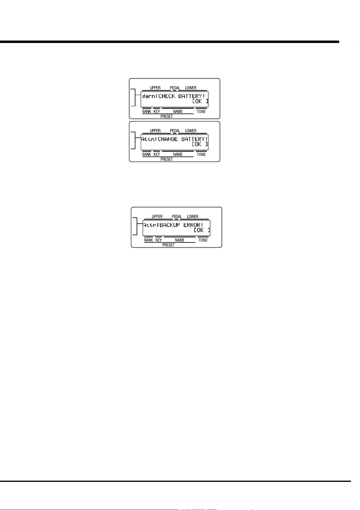
BATTERY BACK UP
Your XK-3C uses a battery-backed RAM to remember your changes to the Parameters.
When the battery voltage becomes low, the Display will show:
If you see these messages, you should immediately back up your parameter changes, if you have made any.
If there is no battery installed in the unit, or if the battery is compeletely dead, the Display will show:
After the above message is displayed, the XK-3C will re-initialize itself, and the factory default settings will
be restored (except Combination Presets, Leslie Cabinets and Cutsom Tone-Wheels). Therefore, it is a good
idea to periodically save your data to CompactFlash card.
CAUTION: In order to change batteries, be sure to ask your dealer or store.
Introduction
Page 6

Table Of Contents
IMPORTANT SAFETY INSTRUCTIONS ............................................ 2
IMPORTANT - PLEASE READ.......................................................... 4
BATTERY BACK UP ......................................................................... 5
Index ................................................................................... 8
MAIN FEATURES ............................................................................ 9
NAMES AND FUNCTIONS ............................................................. 10
Front Panel .................................................................................................. 10
End Block .................................................................................................... 12
Rear Panel ................................................................................................... 13
HOOK-UP ................................................. 15
BASIC HOOK-UP ........................................................................... 16
USING EFFECT LOOP ................................................................... 16
CONNECTING THE LESLIE SPEAKER ........................................... 17
CONNECTING THE MIDI KEYBOARD ............................................ 18
TURN ON AND PLAY ............................... 19
POWER ON ................................................................................... 20
HOW TO POWER ON .............................................................. 20
BACK-UP ................................................................................ 20
RESET TO THE INITIAL STATUS .............................................. 20
RESET FOR XK-SYSTEM ......................................................... 20
LISTEN TO THE DEMONSTRATION PERFORMANCE..................... 21
PLAY WITH THE COMBINATION PRESET ..................................... 22
HOW TO RECALL THE PRESET .............................................. 22
PLAY WITH THE CONTROLLERS .................................................. 23
PITCH BEND WHEEL .............................................................. 23
EXPRESSION PEDAL .............................................................. 23
FOOT SWITCH ........................................................................ 23
TRY TO MAKE YOUR OWN SOUND .............................................. 24
SELECT THE PRESET KEY [B] ................................................ 24
PULL OUT THE LEFT DRAWBARS .......................................... 24
ADD PERCUSSION.................................................................. 24
ADD EFFECTS ......................................................................... 25
VIBRATO & CHORUS ................................................................................... 25
OVERDRIVE ................................................................................................. 25
LESLIE .........................................................................................................25
REVERB .......................................................................................................25
Divide the keyboard into two parts - left and right. [SPLIT] .... 26
Add bass part on the manual keyboard. [MANUAL BASS] ...... 26
What is “Part”? ....................................................................... 26
STORING REGISTRATIONS IN COMBINATION PRESET ........... 27
EX. Memorize to “F - D”. ............................................................................27
SETTING UP............................................. 29
SOUND ENGINE STRUCTURE ....................................................... 30
SYSTEM STRUCTURE OF THIS KEYBOARD ....................................... 30
DRAWBARS™ ............................................................................... 32
MANUAL DRAWBARS......................................................................... 33
WHITE DRAWBARS ..................................................................................... 33
BLACK DRAWBARS .....................................................................................33
BROWN DRAWBARS ................................................................................... 33
PEDAL DRAWBARS ............................................................................ 33
DRAWBAR REGISTRATION PATTERNS ............................................... 34
3 SETS OF DRAWBARS AND PARTS .................................................. 36
MATCH THE REGISTRATION TO DRAWBARS ..................................... 36
PERCUSSION................................................................................ 37
NOTES ................................................................................................ 37
“Percussion does not sound!” ..................................................................... 37
DRAWBAR CANCEL ..................................................................................... 37
VIBRATO & CHORUS .................................................................... 38
TUBE AMP .................................................................................... 39
LESLIE .......................................................................................... 40
EQUALIZER & REVERB ................................................................. 41
EQUALIZER ......................................................................................... 41
REVERB .............................................................................................. 41
COMBINATION PRESETS .............................................................. 42
BANK AND KEY .................................................................................. 42
NAME THE COMBINATION PRESETS.................................................. 43
RECORD INTO THE COMBINATION PRESETS..................................... 44
LOCKING THE COMBINATION PRESET ............................................... 45
USING THE CONTROL PANEL ................ 47
OPERATION CONTROL PANEL ...................................................... 48
PLAY MODE.................................................................................. 49
HOW TO READ THE DISPLAY ............................................................. 49
MENU MODE ................................................................................ 50
HOW TO READ THE DISPLAY ............................................................. 50
BUTTON OPERATION IN THIS MENU .................................................. 50
FUNCTION MODE ......................................................................... 51
HOW TO READ THE DISPLAY ............................................................. 51
BUTTON OPERATION IN THIS MODE .................................................. 51
Example of operation: ......................................................................... 52
SHORT CUT TO THE FUNCTION MODE ........................................ 54
Example of operation: Move to the Percussion Function Mode. ......... 54
RECORD THE PAGE YOU FREQUENTLY USE ................................ 54
Example of operation: Record the Drawbar - Pedal Page .................... 54
*#1 :-%Owner’s Manual
Page 7

SETTING THE PARAMETERS ................. 55
IN THIS MANUAL:
NOTE:s and appear frequently.
The NOTE: is a supplementary explanation.
The are explanations of terms and applications.
DRAWBAR .................................................................................... 56
Setting the Manual Part (LOWER and UPPER) ............................................. 56
Setting the PEDAL Part ................................................................................ 57
PRESET ........................................................................................ 58
PRESET NAME ............................................................................................58
PRESET LOAD .............................................................................................58
EFFECTIVE USE OF LINK-LOWER/PEDAL ............................................ 59
WHEN LINK LOWER/PEDAL IS ON:.............................................................. 59
WHEN LINK LOWER/PEDAL IS OFF:............................................................. 59
ASSIGN......................................................................................... 60
CONTENTS OF ASSIGN TEMPLATES ........................................................... 60
CONTROL ..................................................................................... 62
DRAWBAR ................................................................................................... 62
PITCH BEND ................................................................................................ 62
MODULATION ..............................................................................................63
EXPRESSION ............................................................................................... 64
FOOT SWITCH ............................................................................................. 64
USER ........................................................................................................... 65
DISPLAY ......................................................................................................65
THE EFFECTIVE USE OF THE CONTROL MODE .................................. 66
TUNE ............................................................................................ 67
CUSTOM TONEWHEELS ............................................................... 68
RECORD THE CUSTOM TONEWHEELS ............................................... 70
PERCUSS (PERCUSSion) ............................................................. 71
LESLIE .......................................................................................... 72
CABINET NUMBERS ....................................................................................72
LESLIE PARAMETERS.................................................................................. 72
RECORD THE CABINETS .................................................................... 75
VIB&CHO (VIBrato and CHOrus) .................................................. 76
VIBRATO AND CHORUS OF HAMMOND ORGANS .............................. 77
OVERDRIV (OVERDRIVe).............................................................. 78
BIAS VOLTAGE AND NONLINEAR DISTORTION................................... 79
EQUALIZ (EQUALIZer) .................................................................. 80
REVERB ........................................................................................ 81
DEFAULT....................................................................................... 82
SYSTEM ....................................................................................... 83
MIDI ........................................................... 85
MIDI ............................................................................................. 86
What is “MIDI”? .................................................................................. 86
MIDI TERMINALS ON THIS KEYBOARD .............................................. 86
WHAT THE MIDI CAN DO ON YOUR KEYBOARD ................................. 86
MIDI STRUCTURE......................................................................... 88
EXPANDING THE KEYBOARD ....................................................... 89
RECORDING AND PLAYING THE PERFORMANCE ........................ 90
Recording to the Sequencer or the Computer .............................................. 90
Playback from the Sequencer or the Computer ............................................90
CONTROLLING THE EXTERNAL MIDI EQUIPMENTS .................... 91
ZONES .......................................................................................... 92
INTERNAL ZONE ..........................................................................................92
EXTERNAL ZONE ......................................................................................... 93
MIDI ............................................................................................. 96
MIDI TEMPLATE .......................................................................................... 96
MASTER ...................................................................................................... 96
KEYBOARD CHANNEL ................................................................................. 97
SAVE THE SETUP .................................... 99
SAVE THE SETUP ....................................................................... 100
CF CARD YOU CAN USE ............................................................................ 100
CF CARD SLOT ..........................................................................................100
THE CONTENT AND CAPACITY TO BE SAVED............................................ 100
INITIALIZE THE CF CARD ........................................................... 101
OPERATE THE SETUP ................................................................. 102
HOW TO READ THE DISPLAY ........................................................... 102
SAVE THE SETUP ............................................................................. 102
CHANGE THE SETUP NAME ............................................................. 103
LOADING THE SETUP ....................................................................... 104
HOW TO DELETE THE SETUP ........................................................... 104
TROUBLE SHOOTING ........................... 105
TROUBLE SHOOTING ................................................................. 106
APPENDIX .............................................. 107
Custom Tone-wheel Templates .................................................. 108
MIDI Templates .......................................................................... 109
Part and MIDI Messages ............................................................ 111
MIDI Information ........................................................................ 112
Drawbar Data List 1 ................................................................... 113
Drawbar Data List 2 ................................................................... 113
System Exclusive Message ........................................................ 114
Global Parameters ..................................................................... 115
Preset Parameters ..................................................................... 116
Tone-wheel Parameters ............................................................. 119
Leslie Parameters ...................................................................... 120
System Parameters .................................................................... 120
Combi. and Bank/Program Messages ........................................ 121
Specifications ............................................................................ 122
Demonstration Songs and Composers ....................................... 123
Factory Presets .......................................................................... 124
SERVICE ..................................................................................... 125
Introduction
Page 8

Index
A
Adjust Preset 24, 82, 100
Assign 60
C
Combination Preset 22, 42
CompactFlash Card 100
Custom Tonewheels 68
D
Default 82
Demonstration 21
Display 65
Drawbar 24, 32, 56, 62
E
Effect Loop 16
Envelope 56
Equalizer 80
Expression 23, 64
Master Tune 67
Menu Mode 50
MIDI 86, 96
Modulation 63
N
Noise Gate 83
O
Overdrive 25, 39, 78
P
Part 26
Pedal Keyboard 89
Percussion 24, 37, 71
Pitch Bend 23, 62
Play Mode 49
Preset 58
Preset Key 24
R
V
Velocity 57, 71
Vibrato/Chorus 25, 38, 76
Z
Zones 92
F
Fold-Back 56
Foot Switch 23, 64
Footage 32
Function Mode 51
I
Initial Status 20
Internal Zone 92
K
Key Mode 57, 83
Key-Click 56
L
Leslie 25, 40, 72
Lock 45
Lower Keyboard 89
M
Registration 24, 32, 36
Reverb 25, 41, 81
S
Setup 102
Short Cut 54
Split 26, 92
Spring Reverb 65
Sustain 57
T
Tone-Wheel 56
Transpose 67
Tube Amp 39
U
User 65
Manual Bass 26, 92
*#1 :-%Owner’s Manual
Page 9

MAIN FEATURES
ACCURATELY REPRODUCES THE TONE-WHEEL SOUND.
Your new XK-3C contains (96) independent oscillating digital tone-wheels that accurately reproduce the sound of the
Vintage B-3/C-3.
In addition, this keyboard has full polyphony.
KEYBOARD OPERATES LIKE THE VINTAGE MODELS.
This keyboard operates exactly like the vintage B-3, C-3, etc did.
Presets are selected by means of the Reverse Colored Keys.
Vibrato effects can be selected by the rotary Vibrato control.
The keyboard has Waterfall keys and you can also attach a Leslie Switch (optional) to the front rail as well.
VACUUM TUBE PREAMPLIFIER.
This keyboard has a circuit for a pre-amplifier with 2 characteristically different tubes, a 12AX7 and a 12AU7, so as to
offer a variety of overdrive sounds. The pre-amp circuit consists of dual bands. You can assign bass and treble to
respective tubes, thus can realize purer harmonic sounds. Of course, the general single band operation is also possible.
By adjusting the bias voltage, you can obtain not only the distortion by the general clip but also the nonlinear distortion.
DIGITAL LESLIE / VIBRATO EFFECTS.
The XK-3C keyboard is equipped with a DSP effect generator to simulate the Scanner-Vibrato and Leslie Speaker.
The range of sounds that you can create is expanded by the use of Vibrato and Chorus effects, and by the real sounding
Leslie effects which effectively simulates the rotation of the two Rotors which are present in traditional Leslie.
9
EQUALIZER AND TONE CONTROL.
A 3-band equalizer and tone-control are now built in. The equalizer can make fine or course tonal adjustments to the
bass, treble, and mid frequency ranges. The tone-control simulates the circuit built in on the vintage B-3/C-3 pre-amp to
obtain a gently-cut treble.
11 PIN LESLIE SPEAKER SOCKET.
Your new XK-3C contains a 11 pin Leslie speaker socket for direct connection to Leslie Speakers.
CAN BE EXPANDED BY USE OF EXTERNAL MIDI PRODUCTS.
You can expand your keyboard by connecting and playing with additional external MIDI equipment.
This includes keyboards, sequencers, etc.
CompactFlash™ CARD
You can use a CompactFlash Card (not included) to save various Parameter files.
Introduction
Page 10
10
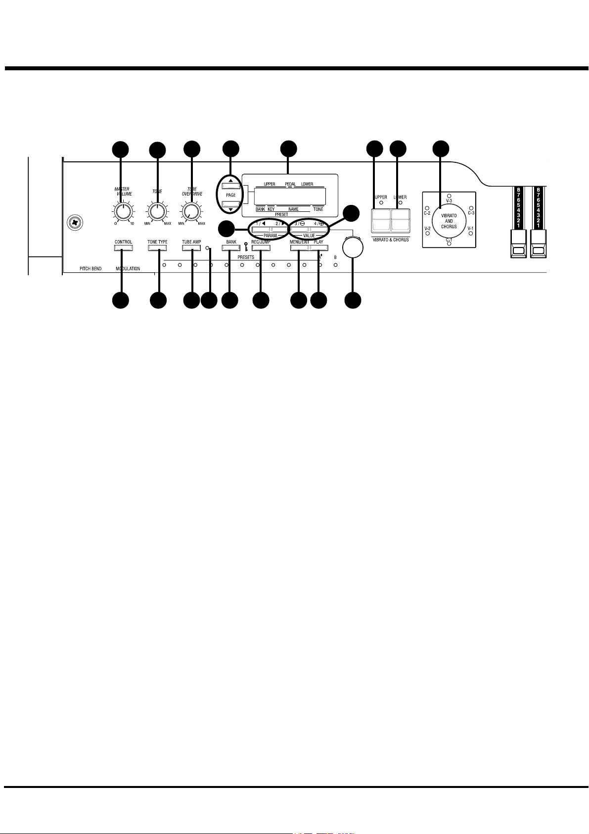
Front Panel
NAMES AND FUNCTIONS
1
3
5
11
2 4 6107 8
UPPER LEFT
1. MASTER VOLUME Knob
Controls the total volume.
2. CONTROL Button
Sets up various controls.
3. TONE Knob
Controls the tone quality.
4. TONE TYPE Button
Assigns the function of TONE CONTROL (3).
5. TUBE OVERDRIVE Knob
Controls the distortion of TUBE AMP (6).
6. TUBE AMP Button
Switches whether the sound of the UPPER/LOWER parts pass
the tube amp circuit.
7. TUBE AMP. LED
Indicates the status of the TUBE AMP.
8. BANK Button
Switches Bank by pressing together the bank switch with the
Preset key (37).
CONTROL PANEL
9. DISPLAY
Indicates various information.
10. PAGE Button
Selects Pages.
9
18 1917
12
1314 15 16
11. PARAM Button
Selects Parameters.
12. VALUE Button
Increases and decreases the value.
13. VALUE Knob
Adjusts the value.
14. REC/JUMP Button
Records Presets. This is also used to allow you to quickly page
through the various choices within each function.
15. MENU/EXIT Button
Recall the MENU screen. This is also used to return from each
function screen.
16. PLAY Button
Jumps to the PLAY screen, the basic screen.
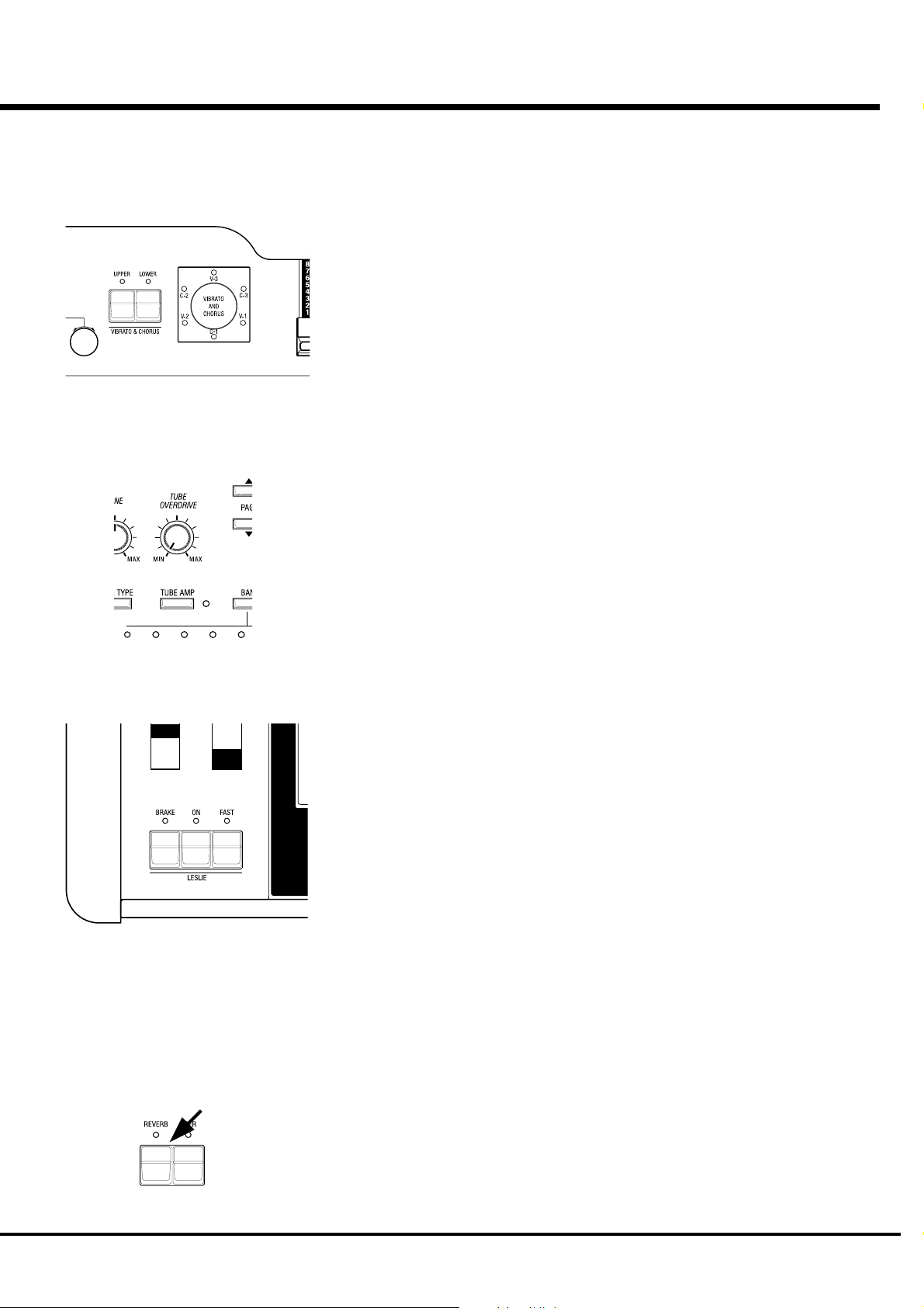
VIBRATO & CHORUS
17. UPPER Button
Switches on and off the Vibrato/Chorus Effects on the UPPER
part.
18. LOWER Button
Switches on and off the Vibrato/Chorus Effects on the LOWER
part.
19. VIBRATO & CHORUS MODE Knob
Changes the depth of Vibrato and Chorus Effects.
*#1 :-%Owner’s Manual
Page 11
11
20
21
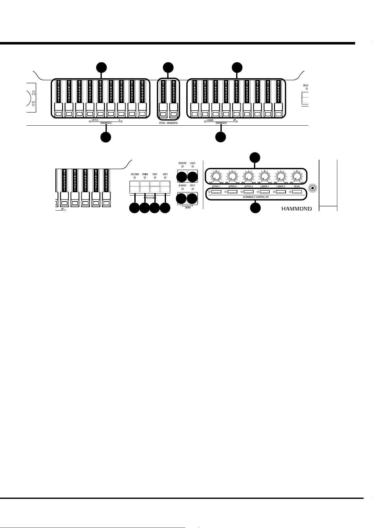
DRAWBARS
20. LEFT DRAWBARS
Controls UPPER part or B key harmonics.
22 23
2526 27 28
24
33
29 30
31 32
34
UPPER RIGHT
29. REVERB Button
Switches on and off the REVERB Effect.
21. LEFT DRAWBARS LED
Indicates the function of the left drawbars.
22. PEDAL DRAWBARS
Controls PEDAL part harmonics.
23. RIGHT DRAWBARS
Controls LOWER part or A< key harmonics.
24. RIGHT DRAWBARS LED
Indicates the function of the right drawbars.
PERCUSSION
25. SECOND Button
Adds 4' Percussion (Decay sound) to UPPER part.
26. THIRD Button
2
Adds 2
/3' Percussion (Decay sound) to UPPER part.
27. FAST Button
Changes Decay time of Percussion.
28. SOFT Button
Changes Percussion volume.
30. USER Button
With this button you can assign the function you want.
PEDAL SUSTAIN ON/OFF is assigned as the factory setting.
31. MANUAL BASS Button
Produces Pedal sound by playing the lowest notes on the manual
keyboard.
32. SPLIT Button
Divides the keyboard into two parts: UPPER and LOWER.
33. ASSIGNABLE Knobs
With this knob you can assign the function you want.
EXTERNAL ZONE VOLUME is assigned as the factory set-
ting.
34. ASSIGNABLE Buttons
With this button you can assign the function you want.
EXTERNAL ZONE SWITCH is assigned as the factory setting.
Introduction
Page 12
12
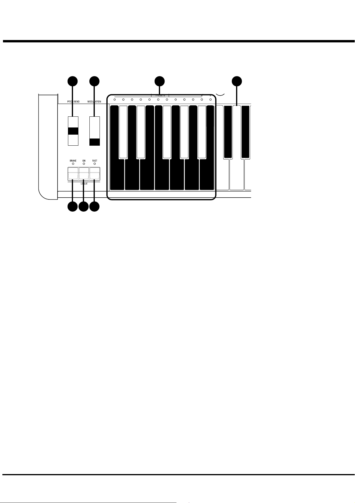
End Block
35
36
37 38 39
WHEEL
35. PITCH BEND Wheel
Slides the pitch up or down.
The pitch goes up when moved up, and goes down when moved
down.
36. MODULATION Wheel
On this keyboard, this is used mainly to send MIDI information
to connected MIDI equipment.
LESLIE
37. LESLIE BRAKE Button
This button selects whether to produce sound from the stopped
rotor (=Brake) or not to use the Leslie effect (= Through) when
the LESLIE ON(38) Button is “off”.
Brake is ON when the LED is on.
40 41
KEYBOARD
40. PRESET Key
This is used to select the Combination Presets.
The Bank is selected by pressing this key, holding down BANK
(8).
The selected BANK/PRESET is indicated by the LED above the
Preset Key.
The “C” key is used to cancel all presets or drawbar settings.
41. MANUAL KEYBOARD
This keyboard contains 61 waterfall shaped keys.
Keyboard is velocity sensitive.
38. LESLIE ON Button
When it is turned ON, the rotor turns and the sound come from
the Rotor.
When the lamp is lighting, it is ‘ON’.
39. LESLIE FAST Button
Changes the speed of the Rotor from Slow to Fast and vice versa.
It is FAST when the LED is on.
*#1 :-%Owner’s Manual
Page 13
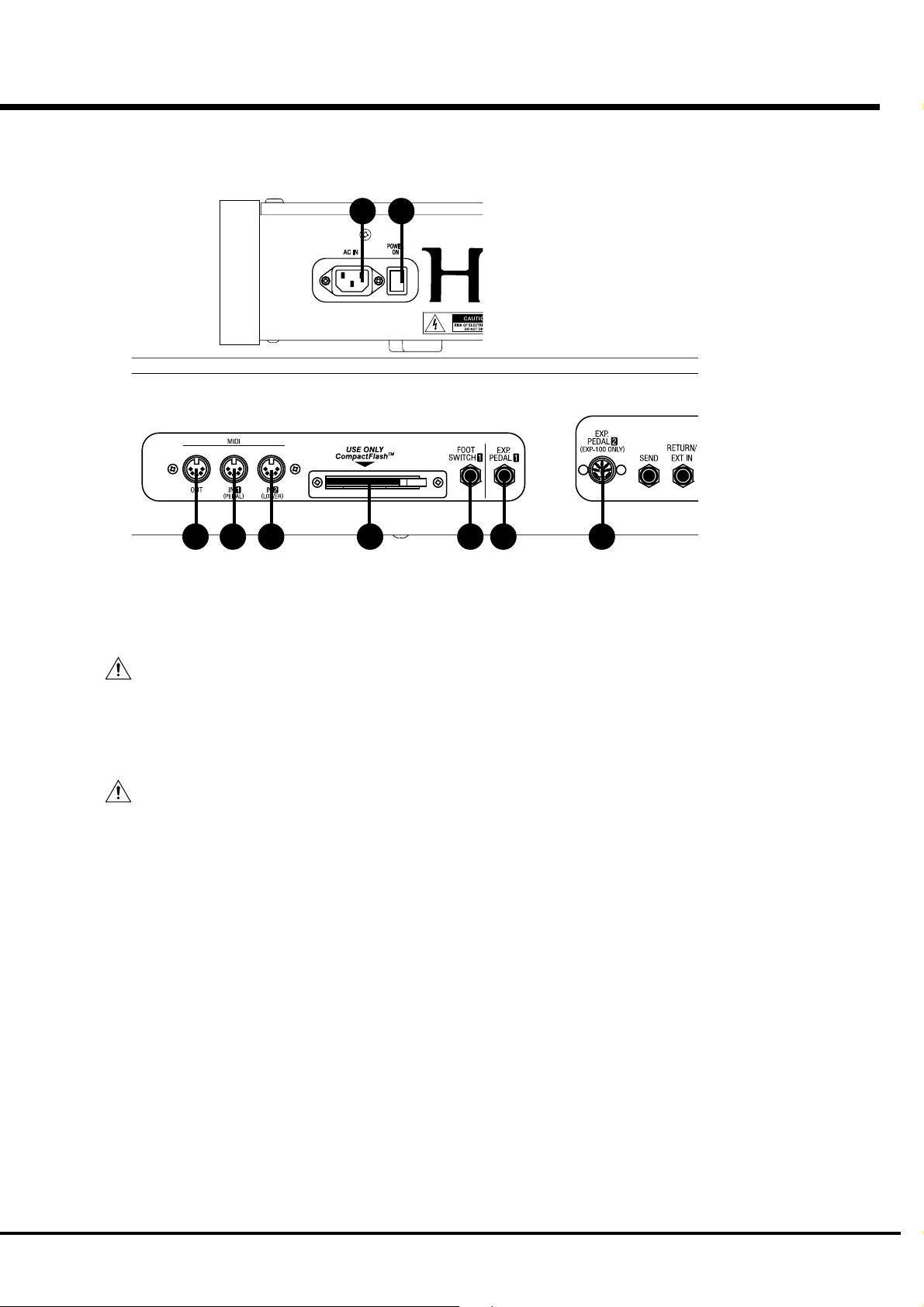
Rear Panel
13
42 43
44 45 46 47 48 49 50
LEFT SIDE OF REAR
42. AC Inlet
Connects the A.C. Power Cable.
CAUTION
This keyboard shall be connected to a MAINS socket
outlet with a protective earth connection.
43. POWER Switch
This switch turns the power ON and OFF.
CAUTION
Even when the POWER switch is turned off, electricity
is still flowing to the instrument at the minimum level.
When you are not using the instrument for a long time,
make sure you unplug the power cord from the wall AC
outlet.
MIDI TERMINAL
44. MIDI OUT
Sends out the performance information of this keyboard.
45. MIDI IN 1(PEDAL)
This is the MIDI IN Terminal used mainly for the Pedal Key-
board.
[The factory setting] The MIDI information received by chan-
nel. You can set that through this terminal functions as PEDAL,
regardless of the channel.
[The factory setting] The MIDI information received by chan-
nel. You can set that through this terminal functions as LOWER,
regardless of the channel.
STORAGE
47. CF CARD SLOT
Insert the CompactFlash™ Card here.
This is used to store the setting of this keyboard.
Use required CompactFlash™ Card.
CONTROLLER TERMINAL
48. FOOT SWITCH1
This terminal is for the Foot Switch (= FS-9H - optional) and the
Leslie Switch (= CU-1 - optional).
You can switch the speed of the Leslie effect and the Combina-
tion Preset, etc. while playing.
49. EXP. PEDAL1
This terminal is for the Expression Pedal (= V-20R etc. - op-
tional.)
You can control the volume while you play.
50. EXP. PEDAL2
This terminal is for the exclusive Expression Pedal (= EXP-100F
or EXP-100AN - optional).
46. MIDI IN 2(LOWER)
This is the MIDI IN Terminal used mainly for the Lower Key-
board.
Introduction
Page 14
14
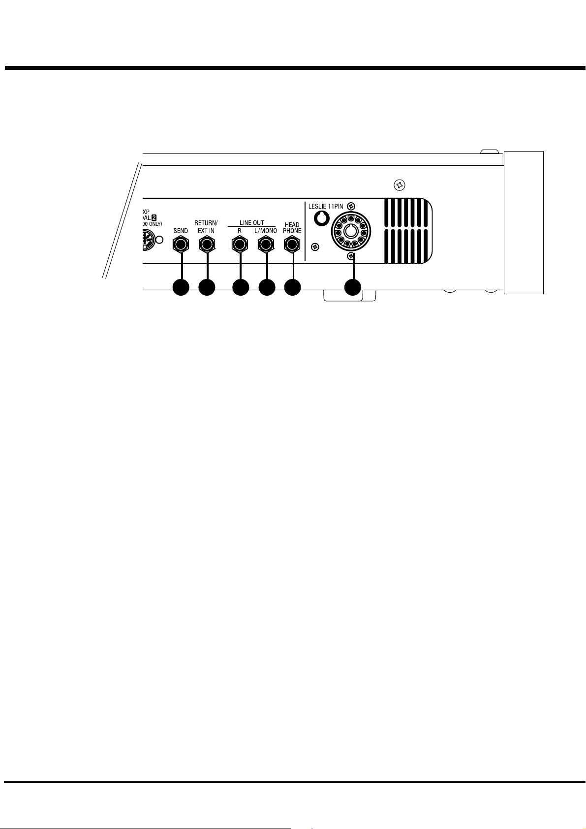
51 52 55 565354
EFFECT LOOP
51. SEND
This jack is for sending to external Effects.
The signal after passing through the built-in Tube Amp. is sent
out.
If you insert a plug into this jack, it disconnects the internal unit,
and signals are not put out from the output jack, except the sig-
nal input from RETURN jack.
(The rated output level is 1.23V +4dBm. The output impedance
is 600Ω.)
52. RETURN/EXT IN
This jack is for receiving external Effects.
This jack can be used as the input jack of a external sound source.
(The rated input level is 1.23V +4dBm. The input impedance is
10kΩ.)
NOTE: Depending on the connected equipment, a setting may
be required for the RETURN jack. (P. 83)
SOUND OUTPUT TERMINAL
53. LINE OUT L/MONO
If your amplifier has only a single (1) female 1/4” audio input
connector (MONO input), use this Jack.
54. LINE OUT R
This is the Right channel output of the XK-3C.
Use the Left and Right output Jacks if your mixer or amplifier
has stereo input.
Use only the L/MONO terminal, if the input is monaural.
The built-in Leslie Effect is only on L (the left), when the Leslie
Speaker (56) is connected.
55. HEADPHONE
This is for connecting the stereo headphones.
Sound is sent out from the LINE-OUT (53, 54) and LESLIE 11PIN
(56), also when this terminal is used.
The built-in Leslie Effect is only on L (the left), when the Leslie
Speaker (56) is connected.
56. LESLIE 11PIN
This is for connecting the Leslie Speaker.
Read “CONNECTING THE LESLIE SPEAKER” for more de-
tails.
*#1 :-%Owner’s Manual
Page 15

HOOK-UP
15
*#1 :-%Owner’s Manual
Page 16

16
BASIC HOOK-UP
See the figure below for connection.
Amplifiers or speakers are not mounted in this keyboard. You must connect an external
amplifiers and speakers (or Powerd Speaker) in order to hear the keyboard sounds.
You can also enjoy playing this keyboard by connecting Stereo Headphones to the Head-
phone Jack.
Be sure to do the connection after you switch the Power OFF on this keyboard and all
connected equipment.
CAUTION
Place this keyboard, making sure or securing the user's easy access to the power switch.
CAUTION
Do not expose this keyboard to any excessive heat sources such as direct sunlight or flames.
Stereo
Headphones
AC Power Cable
(provided)
Foot Switch FS-9H
(optional)
Amplifier, Speakers etc.
USING EFFECT LOOP
The Effect Loop is used when you want to connect the Leslie Speaker and the
external Effects module which provides audio prior to the built-in Leslie Effect.
Use effects modules which have a output gain of less than
+4dB.
NOTE: The Effect Loop is inserted between built-in Tube Amp
and built-in Effect (Leslie, Reverb, etc.)
NOTE: Depending on the connected equipment, a setting may
be required for the RETURN jack. (P. 83)
*#1 :-%Owner’s Manual
Page 17
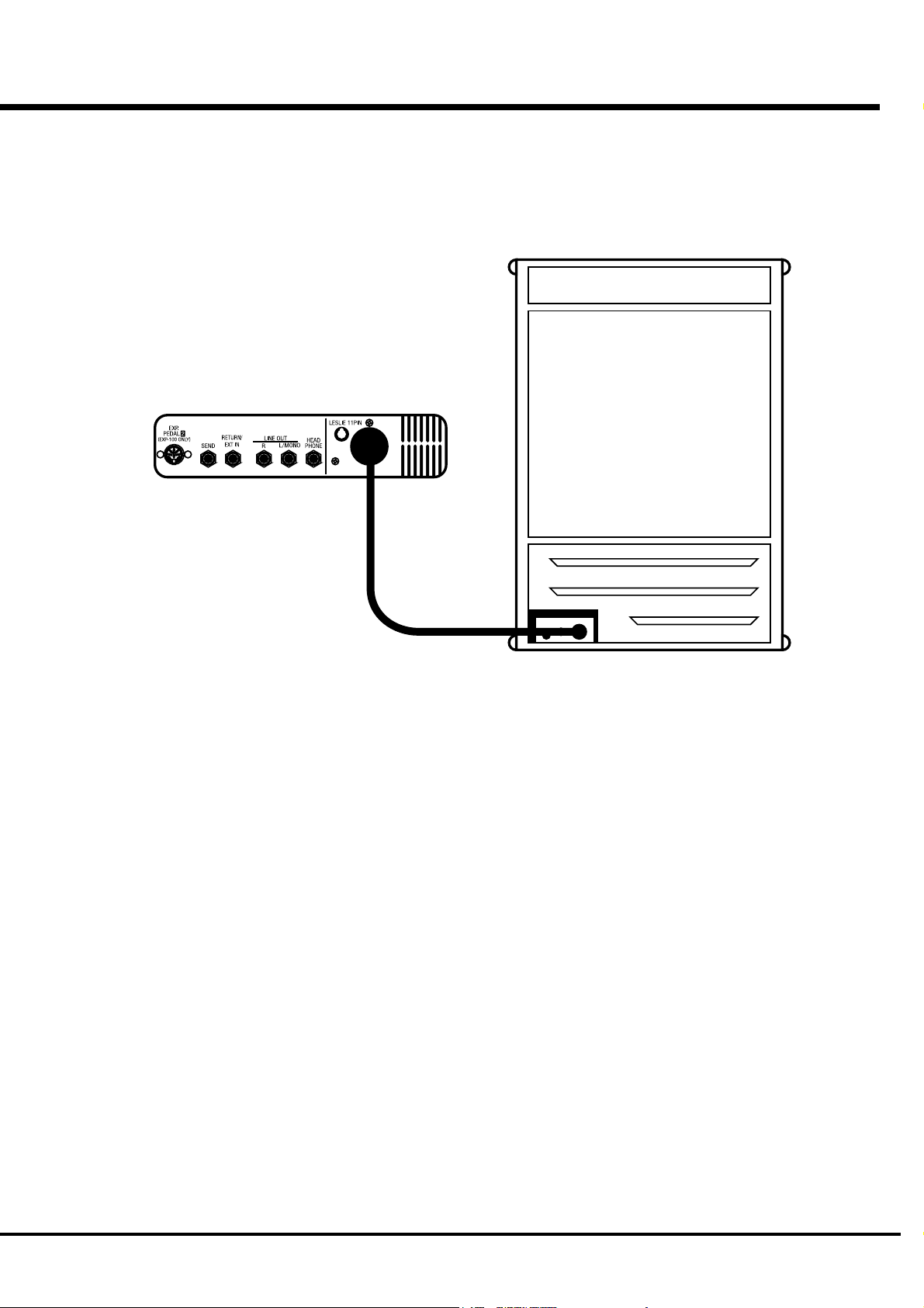
CONNECTING THE LESLIE SPEAKER
This keyboard is equipped with a 11 Pin Leslie Connector, so you can
directly connect the Leslie Speaker.
Do this connection after switching OFF the keyboard.
17
Connect the Leslie Speaker to the 11 Pin Terminal on the
keyboard, with the exclusive 11-Pin Leslie Cable (= LC-
11-7M - to be separately purchased - with the other Leslie
Speaker accessories).
Adjust the setting of the “EXT. LESLIE CH”, in accordance
with the Leslie Speaker connected. (P. 74)
eg. Typical Leslie Speaker Channel
122XB, 3300, 771 -- 1CH
2101/2102, 812/814, 3300 (with Stationary Unit) -- 3CH
Please carefully read the User’s Guide of the Leslie speaker.
Hook-Up
Page 18
18
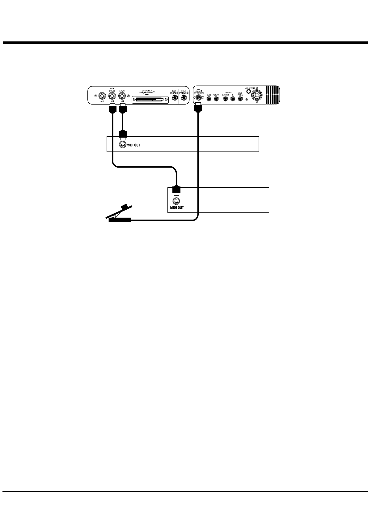
CONNECTING THE MIDI KEYBOARD
You can upgrade this keyboard to an organ by connecting an external MIDI Key-
board and pedal keyboard.
MIDI Keyboard
Expression Pedal
EXP-100F
MIDI Pedal Keyboard
1. Hook-up external MIDI keyboard and pedal keyboard per the figure above.
2. Use the MIDI Template “Seq. Record” of this keyboard. (P. 96 #1)
3. To use Expression Pedal, set the parameter “EXPRESSION SOURCE” for the model of expression pedal that you have connected. (P. 64 #10)
The MIDI Keyboard connected to the PEDAL Jack functions as the PEDAL part, and
the one connected to the LOWER Jack as the LOWER part.
Please also read the User’s Guide of the connected MIDI Keybaord.
Recommend MIDI keyboards
These our products are available:
MIDI LOWER KEYBOARD XLK-3 (61 notes + 12 preset keys)
MIDI PEDALBOARD XPK-100 (13 notes)
MIDI PEDALBOARD XPK-200 (20 notes)
MIDI PEDALBOARD PK-25PXK (25 notes)
*#1 :-%Owner’s Manual
Page 19
TURN ON AND PLAY
19
*#1 :-%Owner’s Manual
Page 20

20
HOW TO POWER ON
After connecting your XK-3C to the power outlet, please perform the following steps before switch-
ing on the power. To avoid possible damages to speakers, please do not change the order of the steps.
STEPS TO TAKE
1. Set the MASTER VOLUME Knob at 0 (minimum), before switching the power on.
2. Switch on the POWER on the rear panel. “PLAY” Mode appears, following the TITLE, in the
It takes a few seconds before the XK-3C gets ready, because of the circuit-protection
It requires 10 to 20 seconds to warm up the tubes to get ready, when the [TUBE AMP]
3. Switch on the power of the amplifiers etc. connected to the XK-3C.
4. Holding down a key, adjust the MASTER VOLUME by turning the Knob.
The Preset Key [B] does not produce sound when initially first turned on. Draw the left
5. Adjust the volume of the amplifiers etc.
Reverse the above steps when you switch off the power. (Switch off the power of the
POWER ON
Display window.
devices.
Button is ON.
Drawbar(s), or press either of the Preset keys [C<] - [A] to start.
amplifiers etc. first.)
BACK-UP
Your XK-3C memorizes the setting of the keyboard immediately before it is switched off. So, The
keyboard will start with these settings when it is switched on again. This is called “Back-up”.
The XK-3C is initially shipped from the factory with the Preset Key [B] in “pressed” status.
RESET TO THE INITIAL STATUS
Please perform the following steps to reset the XK-3C to the initial default setting.
STEPS TO TAKE
1. Switch off the power of the XK-3C.
2. Holding the [REC/JUMP] Button, switch on the power.
3. Hold down / Keep pressing the [REC/JUMP] Button until “Loading Default...” appears on the
Display.
4. If everything is in order, PLAY Mode appears on the Display. (Completed)
RESET FOR XK-SYSTEM
If you want the Upper and Lower manual Reverse color Presets to function just like they do on B-3/
C-3 organ when using the XK-System, follow the above procedure except in step 2 press the [BANK]
instead of [REC/JUMP].
Initial Preset Bank is [B] (refer to Factory Presets), Preset Load (P. 58) works only for Drawbar
registration, Preset - Link Lower / Pedal is “Off”, and MIDI IN mode (P. 96 #2) is “Lower / Pedal”.
*#1 :-%Owner’s Manual
Page 21
STEPS
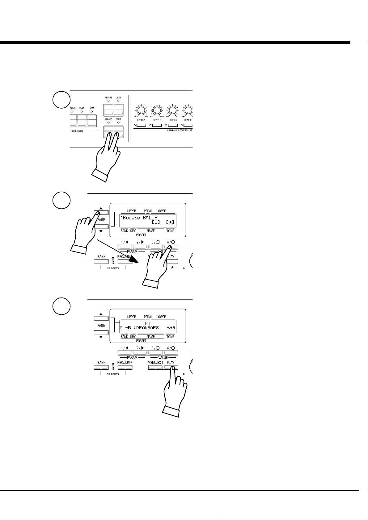
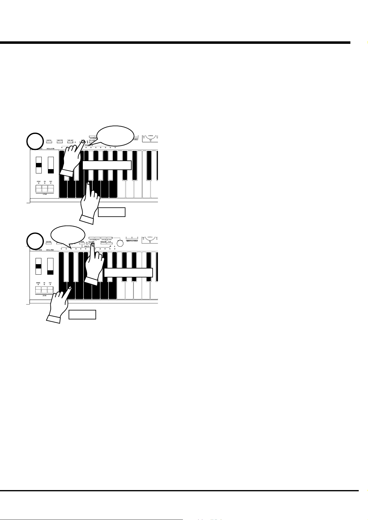
LISTEN TO THE DEMONSTRATION PERFORMANCE
In your XK-3C, the demonstration performance is built in for introducing the
features and sound.
1
Touch and hold the [MANUAL BASS] and [SPLIT] Button for 2
seconds.
The Display will be as shown in step 2.
NOTE: You can locate this mode another way. Touch the
[MENU/EXIT] Button to display the MENU, touch the
[PAGE] Button and select page E, and touch the
[3]DEMO.
21
2
3
Press the [PAGE] Button and select a desired song.
The performance starts when the [4] “X” Button is pressed.
NOTE: After the song is over, the next one starts automati-
cally.
To select a new song while you are playing, touch the [3]“”
Button. The performance that is playing will stop.
NOTE: You can not operate the controllers while playing the
demonstration, except [MASTER VOLUME], [LESLIE
BRAKE], [LESLIE ON], [LESLIE FAST], [VIBRATO &
CHORUS] and [REVERB].
If you press the [M. BASS] and [SPLIT] buttons for holding 2
seconds, and press the [MENU/EXIT] or [PLAY] buttons, the
performance stops.
Turn On and Play
Page 22
22
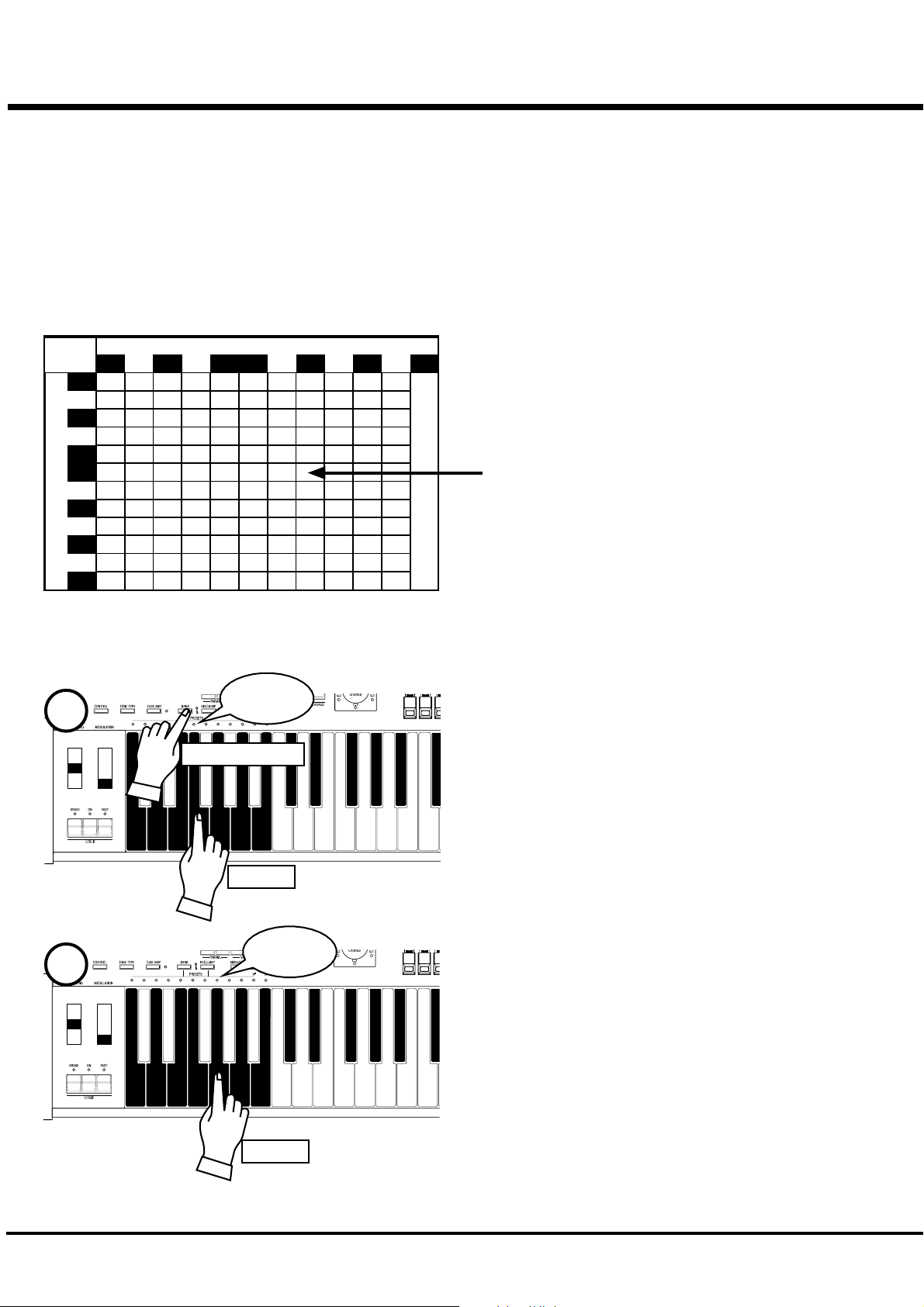
PLAY WITH THE COMBINATION PRESET
You can record various settings to the Preset Keys mounted
on the left-hand side of the XK-3C. This is called “Combi-
nation Preset”.
The Combination Preset consists of the “BANK” and
“KEY” (2-dimensional) such as “C-D”, and appears for
each setting on the Display.
Combination Presets
Key
C C<D D<EFF<G G<A A<B
C
C
<
D
D
<
E
Bank
F
F
<
G
G
<
A
A
<
B
Adjust B
The Preset data is recorded in the Banks C to B at the fac-
tory. Thus you can start playing immediately.
The chart on the left is for the Combination Preset. The “BANK”
is shown vertically (line) and the “KEY” horizontally (column).
Select one combination from this chart and play.
“C - B” is initially selected at the factory.
The example below recalls this.
NOTE: The Preset Key “C” creates no sound (, if combined)
with any Bank in default. This is called “Cancel”.
HOW TO RECALL THE PRESET
EX. Select “F - G”
Light
1
Press and Hold
Touch
Light
2
Touch
1. Select the BANK
While holding down the [BANK] Button, press the Preset Key
[F].
NOTE: The LED for the Preset Key indicates the “BANK”,
while the [BANK] Button is pressed.
2. Select the KEY
Press the Preset Key [G].
At this time the Preset is decided and the setting changes.
NOTE: While the [BANK] Button is released, the LED indi-
cates the “KEY”.
“F - G” appears on the bottom left of the Display.
Recall various Combination Presets and play.
When you recall a Combination Preset, not only Drawbars but
also the Effects such as Leslie and Reverb change altogether.
However, the BANK B of the factory setting changes only the
Drawbars. This action is the same as on B-3 or C-3.
NOTE: You can set the types of the Parameter you recall.
(P. 58)
NOTE: Some Combination Presets cause sound cut-off or
audio interruption, when they are selected while
pressing keys.
*#1 :-%Owner’s Manual
Page 23
PLAY WITH THE CONTROLLERS
Your performance will be more expressive, if you play on the manual using
the controllers. You will see on this page how to use the controllers generally
used with the electronic musical instruments. (How to use the exclusive
Hammond Organ controllers is shown on the next page.)
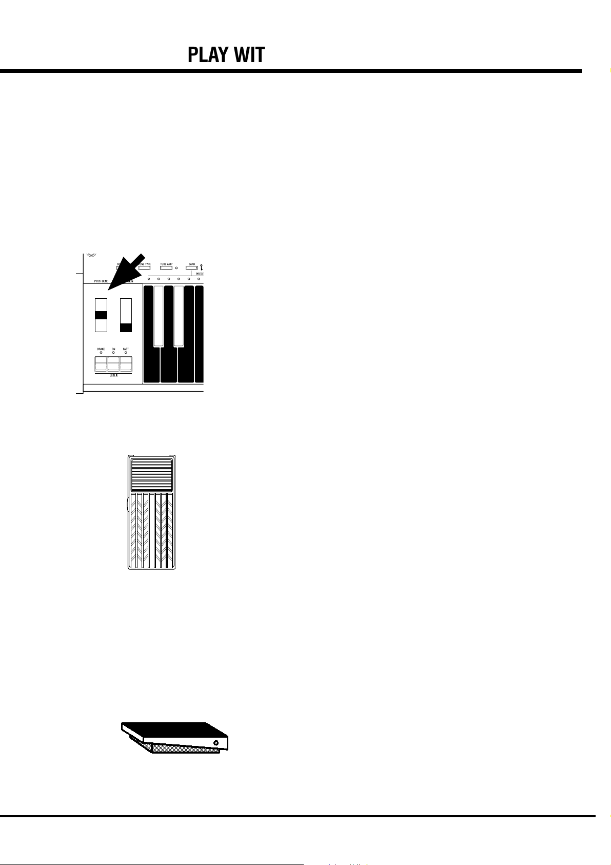
PITCH BEND WHEEL
23
This is used to slide the pitch up or down while playing.
The frequency goes up when you move it back, and it goes down when you move
it forward.
When you release your hand from the PITCH BEND wheel, it returns automati-
cally to the center position.
NOTE: You can adjust the value of the pitch bend. (P. 62)
The [MODULATION WHEEL] on the right is not usually used. It is used when
you transmit the modulation information to external MIDI equipments.
EXPRESSION PEDAL
Fig.: V-20R (optional)
FOOT SWITCH
Generally, organs can not express dynamics or the velocity of the key touch,
while all the piano can.
However, if you connect the Expression Pedal to the organ, you can express the
velocity, corresponding to the degree of your foot-pressure on the pedal, and add
intonation to make your music more expressive. [The Expression Pedal is to be
separately purchased.]
The volume is loudest when you fully press down by means of your toe, and it is
quietest when you fully press down by means of your heel.
NOTE: Set the parameter at “Expression source” for the model of expres-
sion pedal that you have connected. (P. 64)
This switch is used to operate and control the organ by your foot instead of
pressing various switches by your hand while playing. [The Foot Switch is to be
separately purchased.]
The initial factory assignment is “LESLIE FAST”.
NOTE: You can change the Foot switch assignment. (P. 65)
Fig.: FS-9H (optional)
Turn On and Play
Page 24
24
TRY TO MAKE YOUR OWN SOUND
You will be able to freely produce your own sound by using the exclusive features of
your HAMMOND ORGAN, such as Drawbars and Percussion sound, as well as
Vibrato and the Leslie effects. The steps to take after you receive your XK-3C from
your dealer are as follows:
SELECT THE PRESET KEY [B]
First select the Preset Key [B].
This is a special key, also called “Adjust Preset”. While this key is
selected, your setting is always memorized, and the Drawbar regis-
tration on the panel (= the length of the Draw-bars) always corre-
sponds with the internal registration.
NOTE: You can initialize the contents to the default setting. (P.
82)
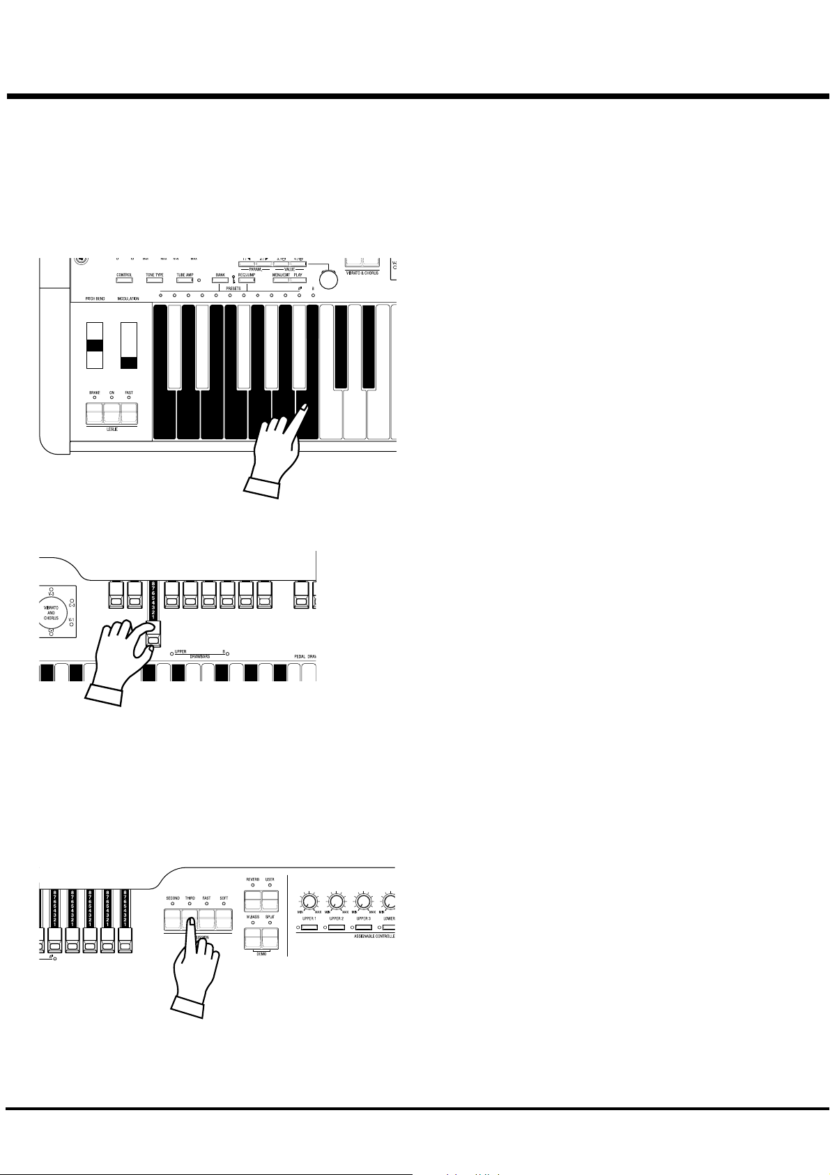
PULL OUT THE LEFT DRAWBARS
Pull out the Left Drawbars on the left-hand side to your desired length, pressing a
key on the keyboard to be certain.
The tone varies corresponding to the extent or the length of the Drawbar. So it is the
Drawbars that make the fundamental tones of this keyboard.
The volume gets loudest when each Drawbar is pulled out to the full length. The XK-
3C gets silent when it is totally pressed back. The tones of the Drawbars gradually
get higher in frequency from left to right.
The most popular patterns or registrations are (1) to pull out only all the three left
side Draw-bars to the full, (2) to pull the far-left and only the white bars to the full, or
(3) to pull all the bars.
NOTE: You can change the characteristics of the Drawbars. (P. 56)
NOTE: The present registration is shown on the “Play” mode display. (P. 48)
ADD PERCUSSION
The “Percussion” referred to here is not a percussion instrument it-
self, but it is a “decay” to add a clear-cut “attack” to the organ sound.
You can add this "attack" to mix with the Drawbar sound when you
want.
If you turn on the [SECOND], [THIRD] Buttons, decays of the har-
monic overtones (= one octave higher “C” and “G”) are added.
If you turn on the [FAST] Button, the decay goes quick. And, if you
press on the [SOFT] Button, the Percussion volume reduces.
NOTE: You can do fine volume setting etc. of the percussion.
(P. 71)
*#1 :-%Owner’s Manual
Page 25
ADD EFFECTS
25
VIBRATO & CHORUS
OVERDRIVE
“Vibrato and Chorus” slightly changes the Drawbar pitch at a certain ratio and add warmth to the
sound.
[UPPER] Button
Switches on and off the Vibrato effect. The LED turns on when it is ON.
[VIBRATO & CHORUS MODE] Knob
Controls the Vibrato Depth and switches to and from the Chorus effect.
The degree of the depth corresponds with the number. Also “V” adds only Vibrato sound by
changing the pitch, “C” mixes Vibrato and original sound (= Chorus Effect) and adds richness to
the sound.
NOTE: You can finely adjust the rotation speed etc. of the Vibrato/Chorus. (P. 76)
The overdrive effect simulates the effect of applying an excessively high signal to the amplifiers
input which causes distortion of the sound.
[TUBE AMP] Button
Press this button to switch on the LED, and get the Overdrive Effect.
[TUBE OVERDRIVE] Knob
This knob controls the degree of distortion.
NOTE: The LED for the TUBE AMP Button varies the color according to the distortion
degree. When it is through the TUBE AMP without distortion, it is green. It goes red
when the distortion degree increases.
NOTE: You can finely adjust the Overdrive Effect. (P. 78)
LESLIE
REVERB
The rotor and the rotating horns produce the effect of the spatial and dynamic and lively theater
stage performance.
[LESLIE ON] Button
Touch “ON” to switch on the LED.
[LESLIE FAST] Button
This button controls the rotor at two different speeds. When the LED is ON, it is FAST. When
the LED is OFF, it is SLOW. The most effective and popular way to use this is to mainly play
SLOW and lead to the climax by changing to FAST.
[LESLIE BRAKE] Button
This is to set the action when the LESLIE ON Button is OFF.
When the LED is ON, BRAKE is on. The rotation gradually slows down and stops finally).
When the light is OFF, it is THROUGH. The Leslie effect is by-passed.
NOTE: You can control the rotors by these buttons when you connect the LESLIE to the
external equipment.
NOTE: You can finely adjust the rotation speed etc. of the internal LESLIE Effect. (P. 72)
This gives the reverberation effect of being in a concert-hall.
[REVERB] Button
To get the Reverb Effect, touch the button and switch on the LED.
NOTE: You can finely control time etc. of Reverb. (P. 81)
Turn On and Play
Page 26
26
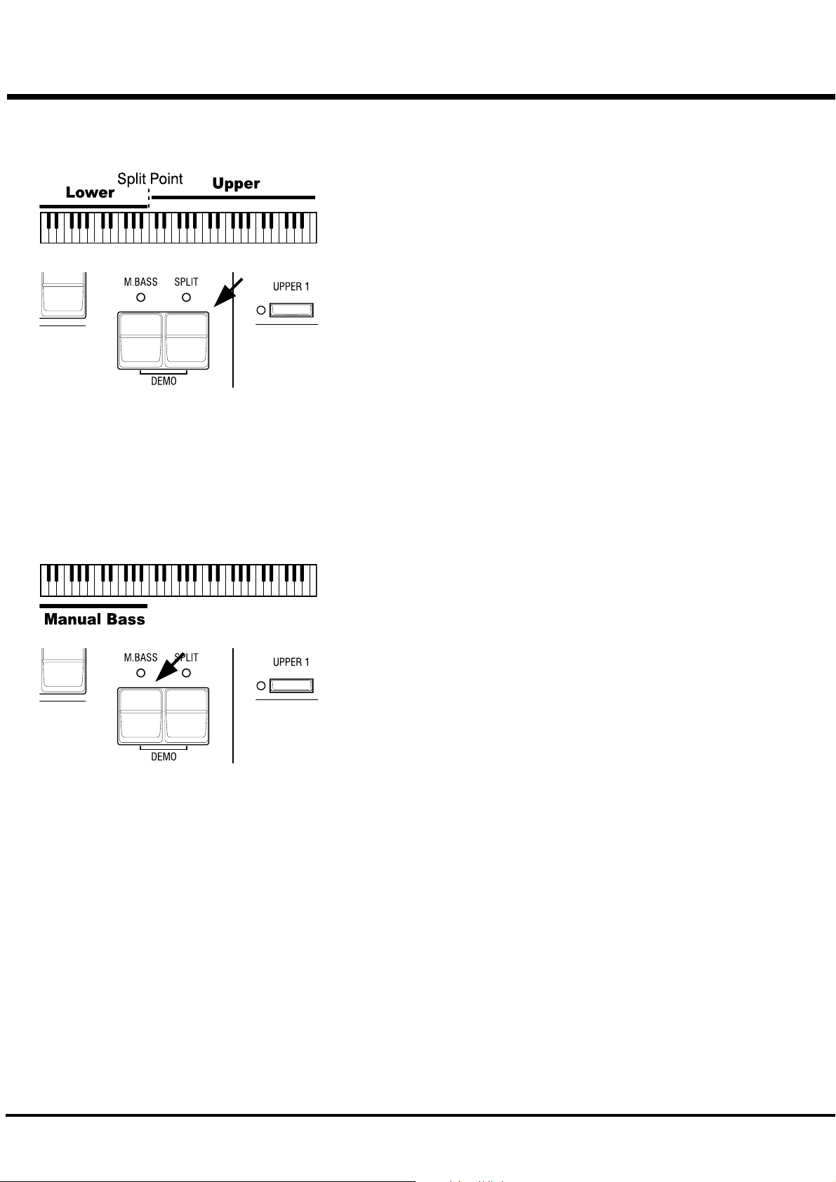
Divide the keyboard into two parts - left and right. [SPLIT]
This keyboard has only a single manual. But you can change the setting and play it as
it was a double keyboard organ, using this “SPLIT” function.
[SPLIT] Button
Switch on the LED by pressing the button, to “split” the manual.
The factory “SPLIT” setting is to divide it between B and C in the center.
NOTE: Split Point or Octave can be moved. (P. 92 #4)
NOTE: The Split function does not work, when the MIDI IN jack is used for
“LOWER/PEDAL”. (P. 96 #2)
The right-hand side of the split point is called UPPER to make sound by the left
Drawbars and Percussion. The left-hand side is called LOWER and makes sound
with the right Drawbars. Percussion does not sound with LOWER.
Add bass part on the manual keyboard. [MANUAL BASS]
You can play the Bass using the lowest keys.
This is called “Manual Bass”.
[M. BASS] Button
To use the Manual Bass function, press the button and switch on the LED.
Not to interfere with the Melody performance, this function is limited only up to B in
the center when it leaves the factory.
NOTE: You can move the upper limit of the Manual Bass. (P. 92 #1)
NOTE: The Manual Bass function is controlled by connected MIDI keyboard
when the purpose of the MIDI IN jack is at “LOWER/PEDAL”. (P. 94 #2)
The bass part obtained by the Manual Bass is called the PEDAL, and makes sound
controlled by the Pedal Drawbars. This is designed so that the Bass is played by the
pedal keyboard as on the three-keyboard organ.
NOTE: You can choose sounding polyphonic (POLY) or lowest note (MONO).
(P. 57 #15)
You can use both the Manual Bass and the Split at the same time. So, you will be
able to play Bass, Chord and Melody all by yourself.
What is “Part”?
A “PART” plays like a “player” in a band or an orchestra does.
Like the three-keyboard organs, this keyboard has three parts, UPPER, LOWER and PEDAL, and so
you can play three different tones.
This keyboard has only a single manual, but it is possible to play plural parts, using the SPLIT and/
or using the MIDI keyboards to expand the keyboard.
NOTE: The function for plural tones is called “Multi-timbre”.
*#1 :-%Owner’s Manual
Page 27
STORING REGISTRATIONS IN COMBINATION PRESET
All the afore-mentioned settings can be memorized to the Combination Preset.
The data stored at the factory can also be freely re-written.
EX. Memorize to “F - D”.
27
1
2
Flash to
On
Touch
Light
Press and Hold
Touch
Press and Hold
1. While pressing the [BANK] Button, press the Preset Key [F].
The LED on the Preset Key indicates BANK while the [BANK] Button is pressed.
NOTE: The LED goes out if you release the button. This means the Preset
is not final.
2. While pressing the [REC/JUMP] Button, press the Preset Key [D].
The Preset is finalized and Recording Preset appears on the display for a while.
When the recording is completed, the LED on the Preset Key [D] flashes for a
few seconds and then switches on. The Display returns to the previous mode.
The recorded Preset will be automatically selected.
The Preset Key [B] (or [A
B”) does not memorize registrations by this operation.
NOTE: The recorded Preset data does not go out if the power is switched
off.
<
] - when the control mode is in “Upper A</
Turn On and Play
Page 28

28
*#1 :-%Owner’s Manual
Page 29

SETTING UP
29
*#1 :-%Owner’s Manual
Page 30
30
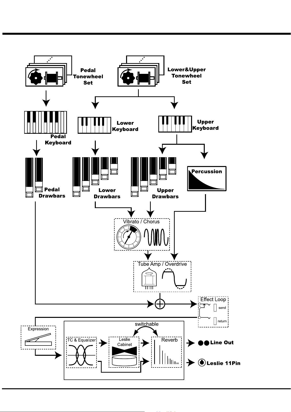
SOUND ENGINE STRUCTURE
SYSTEM STRUCTURE OF THIS KEYBOARD
*#1 :-%Owner’s Manual
Page 31

To fully enjoy playing this keyboard, please read the following section
of this manual.
See the illustrated System Structure of your keyboard on the left page.
31
TONE-WHEELS
The sound source or “engine” of Hammond Organ is the Tone-wheels. They are
like the strings and pick-ups on the electric guitar. While running, each of the 96
Tone-wheels keeps oscillating at a different pitch/frequency.
KEYS
Each of the sound signals made by the 96 Tone-wheels is switched at each key.
Each signal corresponding with each pitch and harmonic is distributed to each
key (as an example, 9 signals for the manual keyboard). The keys are switched
on and off by depressing (= touching) and releasing the keys.
DRAWBARS
The Draw-bars prepare the basic sounds. Each bar adjusts the value of each
harmonic (as an example, 9 harmonics for the manual keyboard).
PERCUSSION
The Percussion makes decay sound, synchronizing with the key touch of the UP-
PER part.
VIBRATO/CHORUS
Vibrato gives vibration to the pitch. By mixing the vibrato sound with the funda-
mental sound, Chorus effect is obtained.
NOTE: On this keyboard the scanner circuit of the B-3/C-3 is simulated, which gives
more effects than the changes of the pitch.
TONE-WHEEL SET
The Tone-wheel Sets are divided into the
Manual Keyboard and the Pedal Part. This is to
give the Pedal Part the Decay (= the sound
gradually fading out while pressing the key) or
Sustain Effect. (= the sound gradually fading
out after the key is released).
HARMONICS
Harmonic is a pitch of a different ratio to a cer-
tain pitch; for example, the one octave higher
C to the middle C. The more Harmonics, the
brighter and richer sound is obtained.
TUBE AMP
Having a real tube in the Amp gives the XK-3C a unique tube sound. By chang-
ing the amount of the drive you can obtain various tube sounds from “clean” no
clipping, to the hard-distorted fuzzy and raspy “overdrive”.
The Pedal Part, however, is designed not to pass through the Vibrato/Chorus or
the Tube Amp, in order to obtain the clear Bass-line.
EFFECT LOOP
If you connect an effector to the effect-loop input (send/return) which is located
on the back of the keyboard, it will no pass thru the overdrive tube amp.
EQUALIZER, LESLIE and REVERB
The sound comes out of the output terminal, after passing the spatial effects: the
Equalizer (for tone regulation), the Cabinet (for the rotating speaker effects) and
the Reverb (for resonance). The built-in Leslie Effect does not work at the Leslie
11-pin terminal.
NOTE: The built-in Leslie Effect is designed to smoothly simulate the rotations of the
two rotors.
Setting Up
Page 32

32
DRAWBARS™
The 9 Drawbars (plus 2 for the Pedal) on this keyboard are used to make the basic sounds.
Each Drawbar is marked with the numbers 1 - 8. If you push back the Drawbar until you can
not see any number at all, the sound of the Drawbar is not heard. If you pull it out to the fullest
position THE SOUND LEVEL is maximum.
Except when the Preset Key is B, the actual Drawbar Registration is the value displayed in the
(display-)window. The “Drawbar Registraion” shows the length of the pulled-out Drawbar(s).
The display shows only the Drawbar(s) you operate.
The pitch of each Drawbar is as shown above, when the middle C is depressed. The footage
marked (') on each Drawbar is originated from the length of the pipes of the pipe organ.
The numbers 1 - 8 on each Drawbar indicate the volume of the sound to be produced as well as
the guide to simply set the Drawbar.
For example, when you blow clarinet, the internal air vibrates, and the fundamental (8') and the
third harmonic (22/3') plus the fifth harmonic (13/5') come out at the same time. On this key-
board, if you pull out 3 Drawbars, you can get the clarinet sound. If you pull out the right hand
side one of the 3 Drawbars a little longer and the left hand side one a little shorter, the element/
component of the high pitch increases and a hard sound comes out. If you pull out the left hand
one a little longer, on the contrary, the sound gets mellow.
Thus, you can make delicate changes to the sound, depending on the flow of the tune/music or
your choice/preference, by fully utilizing the Drawbars.
NOTE: You can change the characters of the Drawbars. (P. 56)
*#1 :-%Owner’s Manual
Page 33

MANUAL DRAWBARS
WHITE DRAWBARS
BLACK DRAWBARS
33
In each Drawbar set, the white Drawbar (8') on the left end makes the basic/
fundamental sound. The other white Drawbars get higher by the octave to
the right.
The sounds of the black Drawbars, too, play important roles in building rich
tones. Their pitches are fifth and third to the fundamental. They contain the
elements of all different harmonics of such as the sweet and soft horn, mel-
low strings and so on.
BROWN DRAWBARS
PEDAL DRAWBARS
The two brown Drawbars on the far left have the role to give depth and
richness to the sound. The left 16' is one (1) octave lower than the 8', and
51/3' is the third harmonic of the 16' fundamental.
Normally, the tones are built on the 8' fundamental, but, if you want to add
depth to the tone or to expand the playing range on the manual by one (1)
octave, the tones are built on the 16' fundamental.
The Pedal Part for playing the bass line usually uses the two Drawbars -16'
and 8'.
The first Pedal Drawbar produces a tone at 16' pitch for a deep foundation
bass, while the second Pedal Drawbar produces a tone at 8' pitch, or one
octave higher.
The registration of the Pedal Part is displayed on the center of the display,
left one is 16', and the right one is 8'.
Setting Up
Page 34

34
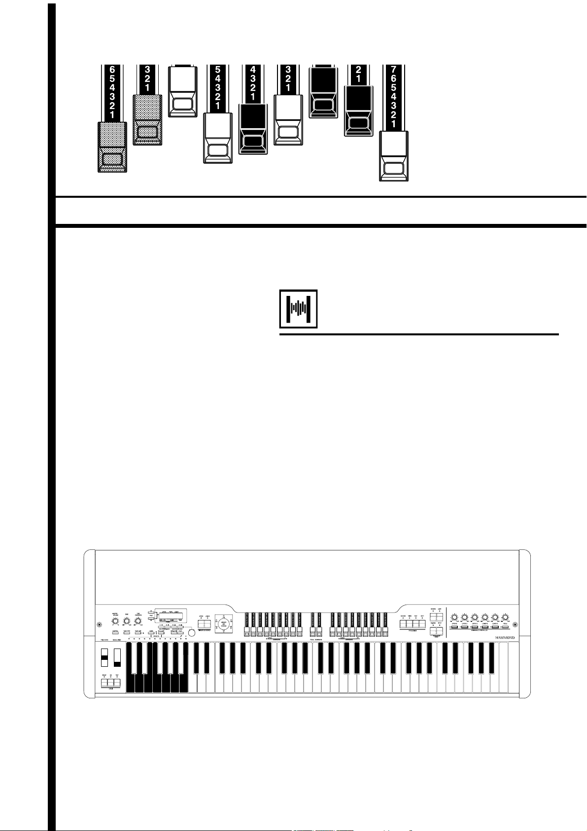
DRAWBAR REGISTRATION PATTERNS
The Drawbar Registration is matched by digits, if precisely. However, in the usual play, it is rather
reasonable to remember the typical combinations of the 9 Drawbars by their forms/shapes.
The Drawbar Registrations are roughly grouped into the following 4 patterns:
Flute family (2 step pattern)
Accompaniment Flute 8' I
Accompaniment Flute 8' II
Accompaniment Flute 8' III
Chorus of Flutes 16'
Orchestral Flute 8'
Piccolo 2'
Stopped Flute 8'
Tibia 8'
Tibia 4'
Tibia (Theater) 16'
Wooden Open Flute 8'
00 8460 000
00 3220 000
00 8600 000
80 8605 002
00 3831 000
00 0006 003
00 5020 000
00 7030 000
00 0700 030
80 8605 004
00 8840 000
Reed family (triangle pattern)
Bassoon 16'
Clarinet 8'
English Horn 8'
Flugel Horn 8'
French Horn
Kinura 8'
Oboe 8'
Trombone 8'
Trumpet 8'
Tuba Sonora 8'
Vox Humana 8'
44 7000 000
00 6070 540
00 3682 210
00 5777 530
00 7654 321
00 0172 786
00 4764 210
01 8777 530
00 6788 650
02 7788 640
00 4720 123
*#1 :-%Owner’s Manual
Page 35

Diapason family (check mark pattern)
Accomp. Diapason 8'
Chorus Diapason 8'
Diapason 8'
Echo Diapason 8'
Harmonic Diapason 16'
Harmonic Diapason 8'
Harmonic Diapason 4'
Horn Diapason 8'
Open Diapason 8'
Solo Diapason
Wood Diapason 8'
35
00 8874 210
00 8686 310
00 7785 321
00 4434 210
85 8524 100
00 8877 760
00 0606 045
00 8887 480
01 8866 430
01 8855 331
00 7754 321
String family (bow pattern)
Cello 8'
Dulciana 8'
Gamba 8' I
Gemshorn 8'
Orchestral String 8'
Salicional 8'
Solo Viola 8'
Solo Violin 8'
Viola da Gamba 8'
Violina 4'
Violone 16'
00 3564 534
00 7770 000
00 3484 443
00 4741 321
00 1464 321
00 2453 321
00 2474 341
00 3654 324
00 2465 432
00 0103 064
26 3431 000
Setting Up
Page 36

36
3 SETS OF DRAWBARS AND PARTS
On this keyboard, there are 3 Parts: UPPER, LOWER and PEDAL, and each of them has the
corresponding Drawbars.
The manual on the keyboard is usually assigned to the UPPER position. If you want to play the
LOWER or PEDAL Part, use the Split or Manual Bass functions, or connect the MIDI keyboard
and assign each part.
There are lamps(= LED’s) in front of the two sets of 9 Drawbars, marked with “UPPER/ B” and
“LOWER/A<”. They indicate the assignment of the Drawbar Sets. They are assigned to UPPER
and LOWER when shipped from the factory.
A< and B are used when you want to operate it like the Upper Manual of the B-3/C-3. In this
case, both Drawbar Sets correspond with the Preset Key A< and B, and control only the UPPER
Part. The LOWER Part is not controled. Please read the CONTROL Chapter for further details.
(P. 62 #1)
MATCH THE REGISTRATION TO DRAWBARS
If you recall the Combination Preset, the Drawbar Registration is not physical but is replaced
with the recorded/memorized one. If you move any Drawbar at this stage, only the Footage
moved is reflected.
To match only the Registration to the Drawbars, while using the content of the Combination
Preset, keep depressing the Preset Key for a while. Combination Preset is recalled and then the
physical Drawbar Registration is reflected.
Touch and Hold
*#1 :-%Owner’s Manual
Page 37

PERCUSSION
The attack feeling of the percussion is a Hammond exclusive.
Percussion is usually used with the Drawbar sound.
[SECOND] BUTTON
The second harmonic, or 4' Drawbar decay, is added to the UPPER Part.
To use this, press the [SECOND] button, and the LED will light.
[THIRD] BUTTON
The third harmonic, or 22/3' Drawbar decay, is added to the UPPER Part. By mixing it with
the Drawbars, power and solidness is obtained.
To use this, press the [THIRD] button, and the LED will light.
37
DECAY
The piano sound gradually goes out even
if you keep the key down. This is called “de-
cay”. The violin, on the contrary, keeps
sounding at a certain volume. This is called
“sustain”.
[FAST] BUTTON
This cuts short the decay time of Percussion.
It is effective if you use this to play with a clear-cut rhythm in an up-tempo piece.
When the LED is OFF, it is SLOW. It gets “FAST” when you press the [FAST] button, and
the LED will light.
[SOFT] BUTTON
This reduces the volume of Percussion.
When the LED is OFF, it is NORMAL. If you press the [SOFT] button, the percussion level
is soft, and the LED will light.
NOTE: You can fine-adjust Percussion. (P. 71)
NOTES
“Percussion does not sound!”
The factory default setting: Percussion does not produce sound except at the Preset Key
[B], if the Combination Preset is Bank B. (See left.) This setting is the same as on the B-
3/C-3.
NOTE: You can set any Preset Key to sound Percussion. (P. 58 #5)
DRAWBAR CANCEL
When either the [SECOND] or the [THIRD] button is ON, 1' in the Upper Part Drawbars
does not produce sound. This is the same action as on the B-3/C-3.
NOTE: You can set to play 1' Drawbar, while Percussion is ON. (P. 71 #8)
Setting Up
Page 38

38
VIBRATO & CHORUS
VIBRATO adds warmth to the tone, by slightly changing the Drawbar pitch at a
certain speed.
You can also add richness to the sound by mixing the Vibrato sound with the funda-
mental (= Chorus Effect).
[UPPER] BUTTON
This switches ON and OFF Vibrato and Chorus Effects.
It affects the UPPER Part.
To get this effect, press the button and the LED will light.
[LOWER] BUTTON
This switches ON and OFF Vibrato and Chorus Effects.
It affects the LOWER Part.
To get this effect, press the button and the LED will light.
[VIBRATO & CHORUS MODE] KNOB
This knob controls the depth of Vibrato and switches ON and OFF the Chorus Effect.
V-1: Comparatively slight Vibrato
V-2: Standard depth Vibrato
V-3: Deepest Vibrato
C-1: Comparatively slight Chorus
C-2: Standard depth Chorus
C-3: Deepest Chorus
NOTE: While the power is ON, either of Vibrato and Chorus is selected.
NOTE: You can fine-adjust the Vibrato and Chorus Effect. (P. 76)
*#1 :-%Owner’s Manual
Page 39

TUBE AMP
The TUBE (= Vacuum Tube) AMP produces a unique “Tube Feeling” sound.
By changing the amount of the Drive, various Tube Sound is obtained, from the
unclipped clean to the hard-distorted fuzzy, raspy Overdrive sound.
39
[TUBE AMP] BUTTON
This is for determining whether or not to go through the Tube Amp circuit.
To get this effect, touch the button and and the LED will light.
NOTE: You can see the tube through the ventilation hole on the back.
[TUBE OVERDRIVE] KNOB
This is for adjusting the distortion value of the Tube Amp circuit.
It does not clip, if turned to the left all the way, but the tone quality is slightly different
from when the [TUBE AMP] button is OFF, because it passes through the Tube Amp cir-
cuitry.
As you turn it to the right, the distortion value increases, and the color of the LED of the
[TUBE AMP] button changes from green to red, in accordance with the amount of distor-
tion.
NOTE: You can fine-set the distortion degree. (P. 78)
TUBE AMP CIRCUIT
Tubes are rarely used in modern electric
apparatuses but because semi-conductors
are better characteristics and because
tubes are inferior in many aspects.
However, in some areas, tubes are again
popular because of their specific charac-
teristics, which are produced only by tubes.
People are still searching for the sound
simulating that of tubes for effectors.
In this keyboard, a real Tube circuit is used.
Setting Up
Page 40

40
LESLIE
LESLIE EFFECT is the simulated sound of the rotating speakers.
If you connect the real Leslie speakers to this keyboard, it controls those (speakers).
[ON] BUTTON
If you touch this button, the LED will light, and the rotor starts turning. Also the
voice is heard thru the rotary channel.
[FAST] BUTTON
This switches the speed of the rotor in two steps. It switches every time you touch it.
When the LED is ON, it is FAST, and when the LED is off, it is SLOW.
[BRAKE] BUTTON
This button sets the action when the [ON] button is OFF.
When the LED is light, it is BRAKE (= The speed gradually slows down and stops.)
and if the LED is OFF, it is THROUGH. (= The Leslie effect is by-passed and the
voice comes out of the stationary channel.)
NOTE: You may not be able to control the Break or Through on some Leslie models.
NOTE: You can fine-set the LESLIE effect i.e. speeds. (P. 72)
In the Leslie speakers, generally, an amplifier and two rotors are
incorporated, i.e. the “Horn Rotor” responsible for the treble and
the “Bass Rotor” for the bass.
Each rotor has a speaker or speakers and a motor for controlling
speed to give the unique trembling sound gained by the Doppler
effect.
There also exist such models as have not only the rotors but sta-
tionary speakers - switchable.
The circuit to send the sound to the rotor is called “Rotary Chan-
nel” and that to the stationary speaker is called “Stationary Chan-
nel”.
The built-in Leslie Effect simulates them and you can get the best
effect when connected stereophonic.
BUTTONS AND LESLIE MODES
Button
BRAKE ON FAST CH=1
On On On
Off On On
On On Off
Off On Off
On Off On
On Off Off
Off Off On
Off Off Off
WHAT IS THE LESLIE EFFECT?
Mode
CH=2or3 &
Internal
Leslie Effect
Fast
Slow
Brake
Fast Through
Slow Through
*#1 :-%Owner’s Manual
Page 41

The Equalizer and the Reverb effects give the final touch to the tone.
The Equalizer regulates the tone, and the Reverb adds the resonance of the hall perfor-
mance.
You can control portions of their functions on the panel buttons and knobs
EQUALIZER
EQUALIZER & REVERB
[TONE] KNOB
One optional Parameter out of the Equalizer is assigned and regulated.
TONE is assigned as the factory setting. If you turn this knob to the right, it gives flat
characteristics and, if to the left, the treble is decreased.
[TONE TYPE] BUTTON
This assigns the settings to the [TONE] KNOB.
At every touch, the assignment changes in the order of [B]ass, [M]iddle, [T]reble, and
[t]one. The initial letter of the word is displayed in the PLAY mode.
NOTE: For further details, please read the section “EQUALIZER” (P. 80)
41
REVERB
The illustration indicates
[t]one is at +9.
[REVERB] BUTTON
This is for switching ON and OFF the Reverb Effect.
To get the Reverb Effect, press the button and the LED will light.
NOTE: You can change the time and the depth of the Reverb. (P. 81)
Setting Up
Page 42

42
The settings you have made can be recorded into the Combination Presets.
BANK AND KEY
Combination Presets
C C<D D<EFF<G G<A A<B
C
C
<
D
D
<
E
Bank
F
F
<
G
G
<
A
A
<
B
Key
COMBINATION PRESETS
The combination preset chart to the left, shows the [BANK] and
the [KEY], information.
Access is made by the Preset Keys. To select the [BANK], press
the key, holding down the [BANK] button. To select the [KEY],
Adjust B
just press the Preset Key.
Recording and recall is determined when the Key is designated.
Only designating the Bank does not switch the recording or re-
call.
Refer to the illustration on the left bottom for each Key and Name.
The [B] key on the right end is a special Preset, called “Adjust
Preset”. Here the Drawbar Registration on the panel always
matches the internal registration.
NOTE: The setting of the Preset Keys [C] to [A] on the B-3/C-3 is
fixed, and the [A
Registration on the panel. However, on this model, you can
change the setting by moving the Drawbars, even while us-
ing the keys [C] to [A].
COMBINATION PRESETS
On the original B-3 organ the preset keys only stored drawbar reg-
istration information. On the XK-3C however in addition to drawbar
registration you can store many various parameters to a preset.
Thus the name “Combination Preset”.
NOTE: The parameters to be recalled by the Preset Keys can be
limited Bank by Bank. (P. 58)
<<
<] and [B] are used to switch the Drawbar
<<
*#1 :-%Owner’s Manual
Page 43

NAME THE COMBINATION PRESETS
Go to the MENU.
1
Touch the [MENU/EXIT] button.
The MENU mode will be displayed.
Go to PAGE A.
2
If the PAGE A is not displayed, touch the [PAGE] button and go
to PAGE A.
43
Go to the PRESET FUNCTION mode.
3
Input THE NAME.
4
Touch the [2] PRESET button and go to the PRESET FUNC-
TION mode.
You can store names up to 10 letters.
[PARAM] BUTTON: moves the cursor.
[VALUE] BUTTON: selects letters.
You can use all the Alphabet letters large and small, signs/sym-
bols and digits.
To jump to the beginning of each list, hold down the [REC/JUMP]
button, and touch the [VALUE] button. You can select letters
etc. by the [VALUE] knob, as well.
The name put here is only temporary. Do the recording opera-
tion to save it, as explained on the next page.
Setting Up
Page 44

44
RECORD INTO THE COMBINATION PRESETS
EXAMPLE: Record into “F-D”.
Select the Bank.
1
Select the Key.
2
Flash to
On
Light
Press and hold
Touch
While holding down the [BANK] button, touch the Preset Key
[F].
The LED on the Preset Key indicates the BANK while you are
holding down the [BANK] button.
NOTE: The LED will be OFF, if you release the button. This means
the Preset is not stored.
This operation is not necessary, if you do not change the Bank.
Press the Preset Key [D], while holding down the [REC/JUMP].
The Preset becomes final and the display shows as follows for a
few seconds.
Recording Preset...
Press and hold
Touch
*#1 :-%Owner’s Manual
When the recording is completed, the LED on the Preset Key
[D] flashes for a while. (The recorded Preset will be automati-
cally selected.)
The display will return to the previous screen.
You can not record to the Preset Key [B] (or [A<] - when
the control mode is in “Upper A</B”) by this operation.
NOTE: The Preset data recorded will not be lost even after you
switch off the power.
Page 45

LOCKING THE COMBINATION PRESET
You can lock the Combination Preset to avoid calling it out by mistake while playing.
To lock the Combination Preset, press both the [BANK]
and the [REC/JUMP] buttons for longer than 1 second,
after calling out the Ccombination Preset you want to lock.
“Preset LOCKED” will be displayed for a certain length
of time and the Combination Preset will be locked.
While the combination preset is locked, the lamp of the
called-out preset key blinks and nothing is recorded to the
combination preset.
To release the lock, keep pressing both the [BANK] and
the [REC/JUMP] buttons again for longer than 1 second.
“Preset UNLOCKED” will be displayed for a certain
length of time and the lock will be released.
If the MIDI IN mode is in “LOWER/PEDAL”, receiving
of the program change also will be locked.
45
Setting Up
Page 46

46
*#1 :-%Owner’s Manual
Page 47

USING THE
47
CONTROL PANEL
*#1 :-%Owner’s Manual
Page 48

48
OPERATION CONTROL PANEL
You now know you can do many settings by using the buttons and knobs on
your keyboard. You can do even finer settings like the delicate speed of the
Leslie Effect or the MIDI equipments, using the display buttons on the Con-
trol Panel.
There are PLAY, MENU and FUNCTION modes in the display.
The buttons and knobs in each mode is explained on the following pages.
PLAY mode
MENU mode
FUNCTION mode
*#1 :-%Owner’s Manual
Page 49

PLAY MODE
The PLAY MODE is the basic display for all the operations. The necessary informa-
tions for the normal play will be displayed.
There are two types of PLAY MODE screens to display the Drawbar Registration.
One is by showing the length of the bars and the other by digits.
To locate this mode:
1. Immediately after powered ON and the start up process is complete, the PLAY mode is
displayed.
2. If a different mode is displayed, touch the [PLAY] button.
HOW TO READ THE DISPLAY
Drawbar registration
UPPER Part/ PEDAL Part/ LOWER Part
49
BAR display
Preset Bank -
Key :
Name
[TONE] knob
Assignment:
DIGITAL display
Preset Bank -
Key on LOWER Part/
Key on UPPER Part
Value of
OVERDRIVE
Advanced Feature - DISPLAY LOCK
Value
These two PLAY mode displays (= the bar dis-
play and the digital display) will be switched ev-
ery time you touch the [PLAY] button.
In the bar display, the Combination Preset name
is shown but another Preset Key, if assigned to
the LOWER Part is not shown.
Also, the function assigned to the [TONE] knob
and its value is displayed.
The Preset name is not shown in the digital mode
display, but you can see the Preset Key of the
LOWER Part.
Also, the value of the Overdrive and the MIDI IN
Note Information is displayed.
Sounding on MIDI Note
Message
This advanced feature allows you to put the organ into a special playing mode
whereby the Control Panel is rendered inoperative. Touching any of the Se-
lect Touch Buttons will have no effect. This is useful when you want to place
the organ in such places as public halls or auditoriums.
To effect this Display Lock function, switch on the power pressing PARAM
[W], [X] and [PLAY]. Then “Display LOCKED...” will be displayed for a
few seconds. To unlock it, do the same thing as above. This time “Display
UNLOCKED..” will appear for a few seconds.
Using the Control Panel
Page 50

50
MENU MODE
The MENU mode is the path for each function.
To locate this mode:
Touch the [MENU/EXIT] button.
There are several pages which contains many various FUNCTION displays. Move from
page to page and find the item where you want to go and touch the numbered button to
see the desired display.
HOW TO READ THE
DISPLAY
PAGE
FUNCTION ITEM
(If none, blank.)
BUTTON OPERATION IN THIS MENU
Moves from a page to
another.
You can jump to the
top or bottom page by
touching these buttons
with holding down the
[REC/JUMP] Button.
Returns to the PLAY mode.
*#1 :-%Owner’s Manual
These are for entering to each FUNCTION
MODE corresponding with the item
displayed.
Page 51

FUNCTION MODE
The FUNCTION MODE is for making each setting and adjustment.
There are many displays, but the basic operation is the same.
HOW TO READ THE DISPLAY
This shows there are PAGEs
above (or below).
PAGE
NAME
VALUE CURSOR
PARAMETER
(Flashing VALUE)
51
This shows there is a PAGE on the
right (or on the left).
CURSOR
In the display window of this keyboard, the
CURSOR is displayed in the flashing style,
while the most popular indicator - cursor
used on the PC, the mobo, etc. is in the
shape of an arrow, a square or an I-shape.
BUTTON OPERATION IN THIS MODE
Moves from a page to
another.
You can jump to the
top or bottom page by
touching these buttons
with holding down the
[REC/JUMP] Button.
Returns to the PLAY
This button is used to move the CURSOR
right or left for selecting the PARAMETER to
change.
The CURSOR moves to the edge of the
display and on to the next page (on the right
or left), if there is one.
Touching this button while holding [REC/
JUMP] button, you can move to the right or
left page regardless where the cursor is.
mode.
The CURSOR increases or decreases
the value of the Parameter.
Holding it increases (or decreases) the
value continuously.
Touching it while holding the [REC/
JUMP] button increases (or decreases)
the value quickly.
The value can also be changed by the
[VALUE] knob on the right bottom
Using the Control Panel
Page 52

52
Example of operation:
Adjusting the DECAY TIME of the Percussion [FAST]
Go to the MENU Mode.
1
Touch the [MENU/EXIT] button.
The [MENU] mode is displayed.
2
Select the PAGE.
Touch the Number button.
3
Search for the PERCUS page, using the [PAGE] button.
“PERCUS” is on PAGE B. So select PAGE [B].
Touch the [2] button for “PERCUSS”.
Now you are on the (first page) of the Percussion Function display.
*#1 :-%Owner’s Manual
Page 53

Move the CURSOR to the Parameter you want to change.
4
DECAY TIME is on the “DECAY” PAGE. Move to that page using
the [PAGE] button.
“FAST” is on the right end. Move the CURSOR (flashing value) to
underneath “FAST” using the [PARAM] button.
Change the value.
5
53
Record into the Combination Presets.
6
The “DECAY FAST” is a Preset Parameter, it will go back to the set value, if you
call out the other (or current) Combination Preset.
If you want to continue to use the changed value hereafter, you must record the
value into the Combination Preset.
Touch and Hold
Decrease the value, using the [VALUE] button or the [VALUE] knob
on the right bottom.
NOTE: Repeat the operation 1 - 5, if you want to change the other param-
eter, too.
PRESET PARAMETERS
They are the Parameters to be recorded into
each Combination Preset.
They include the Parameters for setting the
status of the buttons/knobs on the panel,
“Decay Fast” and many others.
The overall/general common Parameters
(which are not included in the Combination
Presets) are called “Global Parameters.”
Touch
Using the Control Panel
Page 54

54
Each button on the panel has a “SHORT-CUT” capability, so that you can easily go
to each Function mode. By holding down the button, you can easily go to the desired
mode display. You can save time to search the page for the parmeters you want to
change.
SHORT CUT TO THE FUNCTION MODE
Example of operation: Move to the Percussion Function Mode.
For example, if you want change the Percussion setting, you can go
to the PERCUSSION FUNCTION MODE display, by holding down
either [SECOND], [THIRD], [FAST], or [SOFT] for a while. This is
Touch and Hold
called “SHORT CUT”.
Short-cut buttons will be explained in the next Chapter “SETTING
THE PARAMETER”.
NOTE: You can change the time for holding down the button for “SHORT
CUT”. (P. 65 #21)
RECORD THE PAGE YOU FREQUENTLY USE
You can record the page which your usually use, and go to that page by only touch-
ing the [CONTROL] button.
Example of operation: Record the Drawbar - Pedal Page
1
2
Touch and Hold
Touch
Go to the page to be recorded by using MENU etc.
Touch and hold the [REC/JUMP] , and touch the [CONTROL]
button.
Next time, you can come to this page by only touching the
[CONTROL] button.
*#1 :-%Owner’s Manual
Page 55

SETTING THE
55
PARAMETERS
*#1 :-%Owner’s Manual
Page 56

56
DRAWBAR
In this mode, you can set the Parameter relating to the Drawbar sound of each part.
To locate this mode:
Touch the [MENU/EXIT] button and display MENU, touch the [PAGE] button and select
PAGE A and choose [1] DRAWBAR.
7
11 12
8 9 10
2 3
1
4
5 6
Setting the Manual Part (LOWER and UPPER)
1. TONE-WHEELS
Select the TONE-WHEEL SET (waveform) for the manual part.
BTBT
ype1ype1
BT
ype1: The traditional Tonewheel Sound of B-3/C-3
BTBT
ype1ype1
BTBT
ype 2ype 2
BT
ype 2: This sound includes more leakage noise and flutter
BTBT
ype 2ype 2
MellowMellow
Mellow: Transparent sine wave
MellowMellow
BriteBrite
Brite: The analog-oscillating sound represented by X-5
BriteBrite
SawSaw
Saw: Sawtooth waveform.
SawSaw
2. CLICK - ATTACK LEVEL
The larger the value gets, the louder the click volume. At 4 no key click is pronounced.
Also, the smaller the value gets below 4, the slower gets the attack rate (= the drawbars’
starting-up speed).
3. CLICK - RELEASE LEVEL
The larger the value gets, the louder the click volume. At 4 no key click is pronounced.
Also, the smaller the value gets below 4, the slower gets the release rate (= the drawbar
volume’s fading speed).
13
TONE-WHEEL SET
Each Tone-wheel Set allows you to make finer adjustment. (P. 68)
KEY-CLICK
The “Key Click” is the noise heard every time the key is
touched or released on the B-3/C-3, as the voice is
generated by mechanically switching ON and OFF on
these models. The function on this model simulates
the good old noise.
4. CLICK - LPF
This allows you to set the tone of the Key-Click.
The setting range is 0 - 127. The larger the value, the brighter the Key-Click.
5. FOLD-BACK - LOW
This allows you to set at which key the 16' Drawbar starts the FOLD-BACK. (Fold-back:
Repeating the same octave in a certain range on the keyboard.)
The first key (= the far left key on the manual, next to the Preset Keys) is displayed as
“1C”. The setting range is 1C - 2C.
6. FOLD-BACK - HIGH
This allows you to set at which key the 1' Drawbar starts to FOLD-BACK (= repeat the
same octave) in the upper-most range. The set range is 4G - 5C.
NOTE: The FOLD-BACK sets not only the 1' but also 11/3', 13/5', 2' and 22/3' Drawbars.
*#1 :-%Owner’s Manual
EXAMPLE OF CLICK
Simulating the multi-contact keyboard represented by
the B-3/C-3: AT=8, RL=8
Simulating the PCM Synthesizer that only attack pronounces the key click: AT=8, RL=4
Simulating the single-contact keyboard represented by
the X-66: AT=4, RL=4
The slow envelope like the pipe organ: AT=0, RL=0
FOLD-BACK
As the number of the tonewheels was limited on the B3/C-3, the organs were designed to repeat the same
octave in the upper-most or lower-most range. This
feature of this model will simulate that.
Page 57

Setting the PEDAL Part
7. TONE-WHEELS
This allows you to select the Tone-wheel set (waveform) of the PEDAL Part.
NormalNormal
Normal:The traditional B-3/C-3 Tone-wheel sound
NormalNormal
MutedMuted
Muted: Analog-oscillating sound represented by the X-5.
MutedMuted
Synth1Synth1
Synth1: Sawtooth waveform with sweep filter.
Synth1Synth1
Synth2Synth2
Synth2: Dull square waveform.
Synth2Synth2
NOTE: You can locate this page by holding down the [MANUAL BASS] Button as well.
8. ATTACK
This allows you to set the Attack Rate and the Key-Click Volume at ATTACK and RE-
LEASE.
MAX CLKMAX CLK
MAX CLK: Immediate attack and the key-click is loud.
MAX CLKMAX CLK
NORM CLKNORM CLK
NORM CLK: Immediate attack and the key-click is normal.
NORM CLKNORM CLK
SOFSOF
T CLKT CLK
SOF
T CLK: Immediate attack and the key-click is soft.
SOFSOF
T CLKT CLK
NO CLKNO CLK
NO CLK: A slightly slower attack without key-click.
NO CLKNO CLK
SLSL
OW AOW A
SL
SLSL
9. DECAY RATE
This allows you to determine whether to keep a voice on or to set a decay time, while
holding down the key.
The setting range is 1 - 5 and C. The higher the value gets, the longer gets the decay
time. No decay at C.
TKTK
OW A
TK: Slow attack without key-click.
OW AOW A
TKTK
57
10. SUSTAIN - ON
This allows you to set whether or not to use the Sustain function.
It functions at ON.
11. SUSTAIN - LENGTH
This allows you to set the Release Rate (= the decay time after you release the key), when
the SUSTAIN - ON (item #12) is ON.
1 is the shortest, and 5 is the longest decay time.
12. VELOCITY
This allows you to set a value for the Velocity. The setting range is OF and 1 - 4. At OF,
the volume does not change however hard you touch the key. As the value increases
from 1 - 4, the sound gets louder even if you touch the key softly.
When the velocity is 1 - 4, it sounds when you touch the key slightly further
than OF.
13. KEY MODE
This allows you to set the Pedal Part voice mode.
POLPOL
YY
POL
Y: Makes it possible to play harmony (up to 8 notes)
POLPOL
YY
MONOMONO
MONO: Only the lowest note will sound, when you press several keys
MONOMONO
together.
NOTE: The previously released note will be cut when you touch the new one, even when the
PEDAL Part is in the POLY mode and SUSTAIN is ON.
NOTE: When the note-data of the Pedal Part are received from the MIDI IN jack while the
value of the parameter [MIDI IN] (P. 96 #2) is “IN1/IN2”, the Pedal Part produces poly-
phonic sound, regardless of the value.
SUSTAIN
This is the function that the volume slowly fades out
after the key is released, not like that of the synthesizers.
VELOCITY
“Velocity” is the strength to touch the key.
When you touch the piano hard, the hammer hits the
string hard and so the sound gets loud.
In an organ, the sound level does not change however
hard you touch the key.
So this function is effective if you use when the Decay
Rate is other than C, or Decay.
NOTE: All the parameters in these modes are
Preset Parameters. They are recorded
into the Combination Preset.
Setting the Parameters
Page 58

58
PRESET
In this mode, you can name your Combination Presets and determine how to recall
them.
To locate this mode:
Touch the [MENU/EXIT] button and display MENU, then touch the [PAGE] button to select
PAGE A and touch the [2] PRESET button.
2 3 4 5 6 7
3
1
PRESET NAME
1. Preset Name (P)
This allows you to name the present Combination Preset using up
to 10 letters.
Move the cursor by the [PARAM] button, and choose the letters
by the [VALUE] button or the [VALUE] knob.
This change will be lost if you do not record it, same as the other
Preset Parameters.
NOTE: The parameters by the names with (P) on the end are Preset
Parameters, and are recorded to each Combination Preset.
PRESET LOAD
This allows you to set the operation when you depress the Preset
Key.
2. PRESET LOAD - UPPER (B)
This allows you to set whether or not to recall the Drawbar Reg-
istration of UPPER Part.
3. PRESET LOAD - LINK LOWER/PEDAL (G)
This allows you to determine whether or not to recall the Draw-
bar Registration of the LOWER and PEDAL Part.
4. PRESET LOAD - DRAWBAR (B)
This allows you to determine whether or not to recall the Param-
eters relating to the Drawbars of each Part, such as the Tonewheel
Set.
8 9 10
6. PRESET LOAD - INTERNAL ZONE (B)
This allows you to determine whether or not to recall the Param-
eters relating to the Internal Zone such as SPLIT or MANUAL
BASS.
7. PRESET LOAD - EXTERNAL ZONE (B)
This allows you to determine whether or not to recall the Param-
eters relating to the External Zone to control the external MIDI
equipment.
8. PRESET LOAD - EQ/RV (B)
This allows you to determine whether or not to recall the Param-
eters relating to the EQUALIZER and REVERB.
9. PRESET LOAD - ANI/OD (B)
This allows you to determine whether or not to recall the Param-
eters relating to VIBRATO, OVERDRIVE and LESLIE.
10. PRESET LOAD - KNOB & BUTTON (B)
This allows you to determine whether or not to recall the Param-
eters relating to ASSIGNABLE CONTROLLERS.
NOTE: Each Parameter (B) of Preset Load is a Bank Parameter (ex-
cept Link Lower/Pedal). It is set only for the BANK currently
selected. Link Lower/Pedal is a Global Parameter. It is com-
mon on all the BANKs.
5. PRESET LOAD - PERCUSSION (B)
This allows you to determine whether or not to sound PERCUS-
SION with the Preset Keys other than [B] Key and recall the
Parameters relating to Percussion.
*#1 :-%Owner’s Manual
Page 59

EFFECTIVE USE OF LINK-LOWER/PEDAL
This is the function to switch/record only from the connected MIDI equipment, and not to
operate the Preset for LOWER and PEDAL Part on this keyboard.
The Preset Keys on B-3/C-3 are independent, key by key, and so they were operated inde-
pendently. This function simulates that.
59
WHEN LINK LOWER/PEDAL IS ON:
When you recall the Combination Preset by the Preset Key, the
content of all UPPER/LOWER and PEDAL Parts will change.
If you want to change the Lower Part to another Preset Key, send
the Program Change corresponding with the key by the MIDI
keyboard connected to MIDI IN (LOWER) (hereinafter “Lower
Keyboard”).
NOTE: Refer to the Appendix for the details on Program Change
and Keys.
The recording to the Combination Preset is made to all the UP-
PER/ LOWER and PEDAL Parts on this keyboard. It is made
only to the LOWER Part on the Lower Keyboard.
To record to the LOWER Part Preset, send the Program Change
from the Lower Keyboard, depressing the [REC/JUMP] button
of this keyboard.
If different Preset Keys are selected between the UPPER and the LOWER/PEDAL Part, the
display will be like this.
WHEN LINK LOWER/PEDAL IS OFF:
If you recall the Combination Preset by the Preset Key of this
keyboard, the content of only the UPPER Parts will be switched.
To recall LOWER Part Preset, send the Program Change corre-
sponding to the key by the Lower Keyboard.
To the Combination Presets, on this keyboard, only the UPPER
Part is recorded by the Preset Keys, and only the LOWER Part is
recorded by the Lower Keyboard.
LOWER&PEDAL UPPER
Green
Red
Setting the Parameters
Page 60

60
ASSIGN
In this mode, the settings of the ASSIGNABLE CONTROL-
To locate this mode:
LERS are made.
The purpose is assigning functions whenever necessary for
controlling the external MIDI equipment using the external
zones or controlling vibrato or Leslie on the organ by your
right hand. For making the settings easily, several assigning
patterns are available - prepared as templates.
8 9 10
2 3 4
1
ASSIGN TEMPLATES
1. ASSIGN TEMPLATES
This is the mode for easily making the settings purpose by purpose.
Select the purpose by the [PARAM] button and press the [4]RECL button to call out the
typical settings.
Touch the [MENU/EXIT] button and display the Menu. Select
Page A by the [PAGE] button, and touch the [3] ASSIGN button.
CONTROLLERS
2. to 7. ASSIGNABLE BUTTONS
Assign each function to a desired assignable button.
8. to 13. ASSIGNABLE KNOBS
Assign each function to a desired assignable knob.
CONTENTS OF ASSIGN TEMPLATES
EX Sw&Vol
UPPER 1 UPPER 2 UPPER 3 LOWER 1 LOWER 2 PEDAL
KNOB
BUTTON
CC #7 CC #7 CC #7 CC #7 CC #7 CC #7
SWITCH SWITCH SWITCH SWITCH SWITCH SWITCH
DB, Les & Vib
UPPER 1 UPPER 2 UPPER 3 LOWER 1 LOWER 2 PEDAL
KNOB
BUTTON
L&U ATK CLICK L&U RLS CLICK PED. ATTACK PED. DECAY PED. SUS LEN OFF
LESLIE BRAKE LESLIE ON LESLIE FAST OFF VIB. LOWER VIB. UPPER
Eq & Rev
UPPER 1 UPPER 2 UPPER 3 LOWER 1 LOWER 2 PEDAL
KNOB
BUTTON
TONE CONTROL BASS GAIN MID GAIN TREBLE GAIN REV. DEPTH REV. TIME
OFF OFF OFF OFF OFF OFF
Seq Control
UPPER 1 UPPER 2 UPPER 3 LOWER 1 LOWER 2 PEDAL
KNOB
BUTTON
TEMPO OFF OFF OFF OFF OFF
STOP CONTINUE START OFF OFF OFF
*#1 :-%Owner’s Manual
Page 61

61
8
2
9
3
10
4
11 12 13
5 6 7
ASSIGNABLE BUTTONS
The following functions are assignable to the ASSIGNABLE BUTTONS.
EXTEXT
. SWIT. SWIT
EXT
EXTEXT
LESLIE BRAKELESLIE BRAKE
LESLIE BRAKE
LESLIE BRAKELESLIE BRAKE
VIB. LVIB. L
VIB. L
VIB. LVIB. L
STOPSTOP
STOP
STOPSTOP
CHCH
. SWIT
CH
. SWIT. SWIT
CHCH
This function switches SEND ON/OFF to the external zone.
, ON, F, ON, F
ASTAST
, ON, F
AST
, ON, F, ON, F
ASTAST
These function are what the LESLIE [BRAKE], [ON]. [FAST] buttons do.
OWER, UPPEROWER, UPPER
OWER, UPPER
OWER, UPPEROWER, UPPER
These functions are what the VIBRATO [LOWER], [UPPER] buttons do.
, CONTINUE, CONTINUE
, CONTINUE
, CONTINUE, CONTINUE
These functions send each MIDI message.
, ST, ST
, ST
, ST, ST
ARTART
ART
ARTART
11
5
12
6
13
7
ASSIGNABLE KNOBS
The following functions are assignable to the ASSIGNABLE KNOBS.
VOLVOL
UMEUME
, P, P
VOL
VOLVOL
L&U AL&U A
L&U A
L&U AL&U A
PEDPED
PED
PEDPED
BASBAS
BAS
BASBAS
HORN SLHORN SL
HORN SL
HORN SLHORN SL
VIB. TREMOLVIB. TREMOL
VIB. TREMOL
VIB. TREMOLVIB. TREMOL
TONE CONTROLTONE CONTROL
TONE CONTROL
TONE CONTROLTONE CONTROL
BASBAS
BAS
BASBAS
REVREV
REV
REVREV
TEMPOTEMPO
TEMPO
TEMPOTEMPO
CC #2 - 95CC #2 - 95
CC #2 - 95
CC #2 - 95CC #2 - 95
ANAN
UME
, P
AN
UMEUME
, P, P
ANAN
These finely adjust the Volume and Pan of the external zones.
TK CLICKTK CLICK
TK CLICK
TK CLICKTK CLICK
These finely adjust the key-click of the Lower and Upper Part.
. A. A
TT
TT
. A
T
T
. A. A
TT
TT
These finely adjust the envelope of the Pedal Part.
S SLS SL
S SL
S SLS SL
These finely adjust the speed of the built-in Leslie effect.
These finely adjust the tremolo and the speed of Vibrato.
In this mode, they control the tone like a Equalizer does.
S GAIN, MID GAIN, TREBLE GAINS GAIN, MID GAIN, TREBLE GAIN
S GAIN, MID GAIN, TREBLE GAIN
S GAIN, MID GAIN, TREBLE GAINS GAIN, MID GAIN, TREBLE GAIN
In this mode, they control the Gain like a Equalizer does.
. DEPTH, REV. DEPTH, REV
. DEPTH, REV
. DEPTH, REV. DEPTH, REV
These adjust the depth and the time of the Reverb effect.
This sends the MIDI Clock corresponding to the set tempo.
These functions send Control Changes to the external zones.
, L&U RLS CLICK, L&U RLS CLICK
, L&U RLS CLICK
, L&U RLS CLICK, L&U RLS CLICK
ACKACK
, PED, PED
ACK
, PED
ACKACK
, PED, PED
OW SPDOW SPD
OW SPD
OW SPDOW SPD
OW SPDOW SPD
OW SPD
OW SPDOW SPD
OO
, VIB. RA, VIB. RA
O
, VIB. RA
OO
, VIB. RA, VIB. RA
. DECA. DECA
. DECA
. DECA. DECA
, BAS, BAS
S FS F
, BAS
S F
, BAS, BAS
S FS F
, HORN F, HORN F
, HORN F
, HORN F, HORN F
TETE
TE
TETE
. TIME. TIME
. TIME
. TIME. TIME
YY
, PED, PED
. SUS LEN. SUS LEN
Y
, PED
. SUS LEN
YY
, PED, PED
. SUS LEN. SUS LEN
AST SPDAST SPD
AST SPD
AST SPDAST SPD
AST SPDAST SPD
AST SPD
AST SPDAST SPD
,,
,
,,
NOTE: All the parameters in these
modes are Preset Parameters.
They are recorded into the Com-
bination Preset.
Setting the Parameters
Page 62

62
CONTROL
In this mode, you can control the setting relating to each
controller.
You may change the roles of several knobs and switches
mounted on this keyboard. Also, on the rear panel are two
jacks for connecting the Foot-switch and the Expression
Pedal. You must choose either of them in this mode.
22 23
21
17 18 19
10 11 12
9
To locate this mode:
1. Touch the [MENU/EXIT] button and display the MENU and
select PAGE A by the [PAGE] button, and then touch the [4]
CONTROL button.
2. Or, you may touch the [CONTROL] button (in default).
14 15 11
13
16
2 3 4 5 6 7 8
1
DRAWBAR
1. DRAWBAR - CONTROL MODE (G)
This is for setting how the right and left Drawbars function, when [A<] or [B] of the
Preset key is selected.
UPPER/LUPPER/L
UPPER/L
UPPER/LUPPER/L
AA
A
AA
OWEROWER
OWER:
OWEROWER
The left Drawbar controls the UPPER and the right one the LOWER Part re-
spectively.
<<
/B/B
<
/B:
<<
/B/B
While [A<] is ON, the right Drawbar controls the UPPER Part and the left
Drawbar does not operate. Also, while [B] is ON, the right Drawbar does not
operate but the left Drawbar controls the UPPER Part. While [A<] or [B] is
ON, you can not operate the Drawbar Registration of the LOWER Part.
PITCH BEND
2. BEND - L&U DOWN (P)
3. BEND - L&U UP (P)
4. BEND - PEDAL DOWN (P)
5. BEND - PEDAL UP (P)
These are for setting the changing range of the PITCH-BEND WHEEL by the semi-tone.
Both the LOWER and the UPPER Parts change at the same time, as they use the same
Tone-Wheels.
The setting range is 0 - 12 for up, 0 - 24 for down.
*#1 :-%Owner’s Manual
Page 63

63
MOTOR
There is no pitch-bend function on the B-3/C-3.
So some musicians turned off the power while
playing in order to get that effect.
If the B-3/C-3 is turned off, the Tone-wheel motor
gradually slows down and stops, and the amplifier
does as well. This function is to simulate that on
this model.
20
6. BEND - MODE (P)
It switches the function of the PITCH BEND wheel.
BENDBEND
BEND: You can slide the pitch by rotating the PITCH BEND wheel.
BENDBEND
MOTORMOTOR
MOTOR:
MOTORMOTOR
You can control the TONE-WHEEL motor. The motor turns on when it is in the
center or in the neutral position, stops when you rotate it forward (toward
yourself), and accelerates when you push it back.
7. BEND - TIME (P)
This sets the time for slowing down to stop or accelerating the motor when it [= MODE(6)]
is in the MOTOR mode.
The value ranges from 0.1[s] to 5.0[s].
8. BEND - AMPLIFIER (P)
This decides whether to turn off the amplifier or not by rotating the PITCH BEND wheel
forward (toward yourself).
When the value of this parameter is “OF”, the pitch goes down and the sound gradually
fades out.
MODULATION
HOW PITCH BEND MODE WORKS
BEND: The pitch immediately rises.
MOTOR: The pitch gradually rises up to the set
point.
BEND: The pitch immediately comes to normal.
MOTOR: The pitch gradually comes to normal.
9. MODULATION - LESLIE (P)
Assigns the Modulation Wheel to Leslie Speed Function.
OFFOFF
OFF: Does not function.
OFFOFF
SPEEDSPEED
SPEED:If you push back and pull foward the Modulation Wheel, the speed of Leslie
SPEEDSPEED
effect changes fast to slow continuously.
FF
ASTAST
F
AST: If you push back the Modulation Wheel, it is FAST mode, and if you pull it
FF
ASTAST
forward, SLOW.
NOTE: The parameters by the names with (P) on the end are Preset Parameters, and are
recorded to each Combination Preset. (G) is for “Global”. These parameters will be
recorded when set, and are common in each Combination Preset.
BEND: The pitch immediately falls.
MOTOR: The pitch gradually falls down to the set
point.
Setting the Parameters
Page 64

64
EXPRESSION
10. EXPRESSION - SOURCE (G)
Determines what to use for controlling the Expression.
PED1(NORM)PED1(NORM)
PED1(NORM):
PED1(NORM)PED1(NORM)
Uses V-20R etc.
PED1(REV)PED1(REV)
PED1(REV):
PED1(REV)PED1(REV)
Uses KORG XVP-10 etc.
EXPEXP
-100-100
EXP
-100:
EXPEXP
-100-100
Uses EXP-100F.
MIDI INMIDI IN
MIDI IN:
MIDI INMIDI IN
Uses the Expression Information received at the keyboard channel UPPER.
11. EXPRESSION - MONITOR
Displays the present Expression Value. You can find the causes for such troubles as “no
sound”, “non-function” of the Expression Pedal, by checking if the Expression Value
changes normally. Also, this can be a guide when you want to play the “fade in” from
“quiet”.
12. EXPRESSION - MINIMUM LEVEL (G)
It sets the output level when the Expression is minimum.
The setting range is OFF, -40db to 0db. “OFF” makes no sound when the Expression is
minimum, “0dB” does not reduce volume level.
13. EXPRESSION - LIMIT LF (G)
14. EXPRESSION - LIMIT HF (G)
These are for setting the level to maintain for low and high frequencies when the Expres-
sion is minimum.
The setting range is OFF, -40dB to -5dB. This function does not work at “OFF”. Other-
wise the level is maintained even if the Expression is minimum.
EXPRESSION LIMIT
One of the human ear’s characteristics is that when
the volume falls, the sound of high or low frequency
becomes difficult to hear.
On this model, it is rectified. The volume is maintained above a certain level even when the volume
goes down in order to keep the sound of high or
low frequency audible.
The similar function is adopted on most home audio equipments. It is called the “loudness” function.
15. EXPRESSION - GAIN (S)
This is for adjusting the gain (=range of the change) of the connected expression pedal.
It sometimes occurs that even if you press the expression pedal to the bottom limit, the
expression value does not reach the maximum value (127) due to the difference of each
expression pedal model. In such a case, adjust this parameter for getting the maximum
range.
16. EXPRESSION - CURVE (S)
This parameter sets how the value should vary corresponding to the depth of the expres-
sion pedal. The setting range is 1 to 3. Refer to the curves on the bottom right figure.
NOTE: These parameters are System Parameters. These parameters will be recorded when
set. It is common in each Combination Preset. It is not recorded to the “Setup”.
FOOT SWITCH
17. FOOT-SWITCH - 1 DEVICE (G)
This is for deciding which equipment is connected to the Foot Switch 1 jack.
PEDPED
ALAL
PED
AL: for Foot switch.
PEDPED
ALAL
CU-1CU-1
CU-1: for the Leslie switch CU-1 (= optional).
CU-1CU-1
*#1 :-%Owner’s Manual
Page 65

18. FOOT-SWITCH - 1 TIP (G)
This is for setting the function of the Foot Switch 1 jack.
If you are using the Foot Switch with a stereo plug, this sets the function on the tip contact.
OFFOFF
OFF: Does not work.
OFFOFF
LESLIE S/F ALLESLIE S/F AL
LESLIE S/F AL
LESLIE S/F ALLESLIE S/F AL
DD
AMPER UPPERAMPER UPPER
D
AMPER UPPER,
DD
AMPER UPPERAMPER UPPER
PRESET FWDPRESET FWD
PRESET FWD
PRESET FWDPRESET FWD
SPRINGSPRING
SPRING:
SPRINGSPRING
DELADELA
Y TIMEY TIME
DELA
Y TIME:
DELADELA
Y TIMEY TIME
TT
, MOM, MOM
T
, MOM:
TT
, MOM, MOM
These are for switching SLOW/FAST of the Leslie Effect.
At ALT, SLOW/FAST is alternately switched at each step of the Foot Switch, and
it switches OFF if pressed for longer than 1 second.
At MOM, the Leslie effect gets Faster, as long as you keep pressing the foot switch,
and it gets Slower if you release it.
L L
OWEROWER
L
OWER,
L L
OWEROWER
They hold the Notes of the UPPER, LOWER and PEDAL Parts, respectively, as
long as you keep depressing the footswitch.
, REV, REV
, REV:
, REV, REV
They are for switching one Combination Preset to the right (FWD) or the left
(REV).
This is for producing a springing sound of the Spring Reverb.
This function sets the delay time (P. 81 #4) of the reverb effect, by the interval of
pressing the foot-switch. By pressing and holding the foot-switch, the delay sound
will be erased.
PED PED
PED
PED PED
ALAL
AL:
ALAL
19. FOOT-SWITCH - 1 RING (G)
This is for setting the function on the RING contact, if you use the FOOT SWITCH equipped
with the Stereo plug.
20. FOOT-SWITCH - 2 MODE (G)
This is for setting the function of the FOOT SWITCH attached to the Expression Pedal EXP-
100F (= optional).
USER
21. USER (G)
This is for setting the function of the [USER] BUTTON.
PEDPED
AL SUSAL SUS
PED
AL SUS: Switches On/Off Sustain of the PEDAL Part.
PEDPED
AL SUSAL SUS
LL
OWER OCTOWER OCT
L
OWER OCT: Switches 0/+1 of the LOWER Octave.
LL
OWER OCTOWER OCT
LES. BRAKELES. BRAKE
LES. BRAKE: Means the [LESLIE BRAKE] Button.
LES. BRAKELES. BRAKE
LES. ONLES. ON
LES. ON: Means the [LESLIE ON] Button.
LES. ONLES. ON
LES. FLES. F
ASTAST
LES. F
AST: Means the [LESLIE FAST] Button.
LES. FLES. F
ASTAST
VIB. UPPERVIB. UPPER
VIB. UPPER: Means the VIBRATO & CHORUS [UPPER] Button.
VIB. UPPERVIB. UPPER
VIB. LVIB. L
OWEROWER
VIB. L
OWER: Means the VIBRATO & CHORUS [LOWER] Button.
VIB. LVIB. L
OWEROWER
LESONREVLESONREV
LESONREV: Switches On/Off Leslie On Reverb.
LESONREVLESONREV
65
DAMPER
The word “Damper” comes from the damper pedal
of the piano.
The piano stops sounding when you release your
finger from the key. This is because of the damper
system. While you hold the damper pedal, the
system does not work and so it keeps sounding
even after you release the key.
SPRING REVERB
The Spring Reverb is a reverb effect to obtain the
reverberation using the spring resilience. It was
easily affected by a shock and it use to give a big
“clang”.
However, this drawback has come to be used as
an effect in the genre of progressive rock. This
keyboard gives the simulated sound.
TIP AND RING
When you look at the plug of the stereo headphones, there are 3 metal parts. The head por tion
is called “Tip” and the middle portion is the “Ring”.
The part on the cord side is called “Sleeve”.
The ordinary foot-switch has only the Tip and the
Sleeve, but the footswitch with two switches in one
plug or two footswitches using the L/R converting
cable can be connected.
DISPLAY
22. DISPLAY - SHORT CUT (G)
It sets the time limit to the short cut function.
The range is 0s to 2s and NO short cut. The short cut function does not work when the value
is in “NO”.
23. DISPLAY - TIME OUT (G)
It sets the time limit to return to the previous screen from the one displayed by using the short
cut operation.
The range is 4s to 16s and NO time out. The time out function does not work when the
value is in “NO”.
NOTE: The parameters by the names
with (P) on the end are Preset
Parameters, and are recorded to
each Combination Preset. (G) is
for “Global”. These parameters
will be recorded when set, and
are common in each Combina-
tion Preset.
Setting the Parameters
Page 66

66
THE EFFECTIVE USE OF THE CONTROL MODE
The DRAWBAR - CONTROL MODE is normally set on the
“UPPER/LOWER” side.
“UPPER A</B” is used when you want to quickly switch to the
Drawbar Registration, improvised during the performance.
It is like the House DJ's preparing the next tune while playing a
certain tune, using the Cross-Fader.
You can prepare the next registration by the Drawbars for [A<]
during your play by [B]. (No need for the recording operation.)
By pressing the [A<] key next, it is switched to that. You can do
vice versa.
In this case, if you select [A<] or [B] by the Preset Key, the left
and right Drawbars work only for the UPPER Part.
Operate the [B] Registration by the left Drawbars, and the [A<]
Registration by the right ones. (Note the order of the Drawbars
and the Key is different.)
To set the registration for the LOWER Part, first select one from
the Preset Keys [C] ... [A] on this keyboard, then make sounds
using the right Drawbars. To memorize the registration to [A#] or
[B] key, select [A#] or [B] (or on the Lower Keyboard, in case
the keyboard is expanded).
*#1 :-%Owner’s Manual
Page 67

TUNE
In this mode, you can tune and transpose for playing in ensemble with the other instru-
ments.
To locate this mode:
Touch the [MENU/EXIT] button (MENU will displayed), select PAGE B by the [PAGE] button
and touch the [3] TUNE button.
1 2
1. TRANSPOSE
You can transpose the entire keyboard by the semi-tone.
The setting range is -6 to +6.
Transpose effects:
between the manual keyboard and the built-in sound engine, and
between MIDI IN and the built-in sound engine.
External Zone.
If you connect the MIDI Pedalboard XPK-100, the parameter will be changed by the
transpose operation, too.
67
TRANSPOSE AND TONEWHEELS
If you set the transpose value at other than 0, the
relation between the keys and the Tonewheels gets
off. So, if you try to tune the Tonewheels by the
keyboard and the Drawbars at this time, you cannot select the desired wheels.
2. MASTER TUNE
This is for changing the PITCH of this entire keyboard.
The setting range is A = 430 - 450 Hz.
NOTE: The parameters in this mode are the Global Parameters. They are recorded when the
value is set. Also, they are common at each Combination Preset.
Setting the Parameters
Page 68

68
CUSTOM TONEWHEELS
In this mode, you can regulate each Tone-Wheel Set of the
Manual Keyboard, wheel by wheel.
The Tonewheel Set consists of 96 Tonewheels of different
pitches, and one wheel corresponds with plural notes and
the feet of the Drawbars.
The relation is complicated. For example, the middle C of
the 8' and the C one octave lower of the 4' use the identical
wheel.
In this keyboard, you can save 5 types of settings per 1
Tone-Wheel Set. We call this “CUSTOM TONE-
4 5 6 7 8
3
2
WHEELS”.
As a sample for customization, the typical 3 (or 4) types
of settings are recorded when delivered from the factory.
To locate this mode:
Touch the [MENU/EXIT] button and display MENU, select PAGE B by the [PAGE] button, and then touch [1]
CUST. TW button.
1
1. TONE-WHEEL SET
This is for selecting the Tone-Wheel set. Also, the Temporary (=
the present setting) automatically switches to the selected Tone-
Wheel Set just selcted now.
2. CUSTOM NUMBER
This is for selecting the “CUSTOM NUMBER” to use or compile. The “*” will be displayed when the Tone-wheel Param-
eters are changed from this Custom Number.
NOTE: This parameter is a Preset Parameter. It is recorded into the
Combination Preset.
3. CUSTOM NAME
You can put the name on the CUSTOM TONEWHEELS using
up to 10 letters.
Move the cursor by the [PARAM] button and choose the letters
by the [VALUE] button or the [VALUE] knob.
By touching the [VALUE] button while holding down the [REC/
JUMP] button, it jumps to the head/first of each letter type (space,
0, A, a).
The name set here, as well as the Tonewheel parameters below,
will be deleted, if you do not do the recording operation as ex-
plained on the next page.
INITIAL VALUE OF THE CUSTOM NUMBER
The typical settings are saved to the Number 1 - 3 (or
4), as the initial value.
For example, to the BType1, “Real B-3” simulating the
well-preserved B-3/C-3 and “80’s Clean” with less
noise, rough sound “Noisy”, and “Noisy 60” with louder
leakage noise is stored.
*#1 :-%Owner’s Manual
Page 69

4. WHEEL NUMBER
Select the Number of the Wheel you want to regulate.
To select the Wheel Number, select the [VALUE] button or
the [VALUE] knob here, or slightly move the feet of the Draw-
bar while depressing the key you want to regulate. (See the
illustration on the right.)
When the Wheel Number is selected, each parameter for the
wheel (5, 6, 7, 8) is displayed.
5. LEVEL
This is for setting the volume of this wheel.
The setting range is -20 to +2dB. If you increase the value, it
gets louder.
6. CUT OFF FREQUENCY - LPF
This is for setting the FREQUENCY to cut the TREBLE of
this wheel.
If you increase the value, a leakage noise is heard besides
the original tonewheel pitch.
If you decrease the value, the sound gets sweet and mild, as
the treble is cut off.
The setting range is 0 - 127.
NOTE: If you decrease the value too low below the original
Tonewheel pitch, the wheel volume will be reduced.
69
How to select the WHEEL NUMBER
Concept of the LEVEL ADJUSTMENT
7. RESONANCE - LPF
This is for setting the boost or reduce the level in and around
frequency by Cut-Off Frequency - LPF(5).
The setting range is -100 to +100. The more the value gets
boost, and less the value treble is cut smoothly.
8. CUT OFF FREQUENCY - HPF
This is for setting the FREQUENCY to cut the BASS of this
wheel.
If you decrease the value, a motor hum (= noise) is heard
besides the original Tonewheel sound.
The setting range is 0 - 127.
NOTE: If you increase the value too high above the original
tonewheel pitch, the sound will get “thin”.
NOTE: The parameters 2 - 7 are the Tonewheel parameters. If
you do the recording operation of the next page, it works
commonly to the same Tonewheel Set of each Combi-
nation Preset.
NOTE: When you operate the parameters 2 - 7, if you do not
the recording operation of the next page, it is lost when
you turn off the power.
LEAKAGE NOISE
On the B-3/C-3, the signal leakes in the route from
the pick-up mounted for the Topnewheels to the
output terminal, thus noise (= mixed Tone-wheel
sound) was also heard, This is called “Leakage
Noise”.
The “Leakage Noise” is an obstacle in making pure
tones, but it is recognized as a character now.
“Mellow”, “Brite” and “Saw” does not include the
Leakage Noise.
DISTORTION
If you raise the Level and Resonance values too
much, it changes the gain in the sound engine and
may sometimes cause distortion, i.e. unpleasant
noise.
In such a case, please lower these values.
Setting the Parameters
Page 70

70
RECORD THE CUSTOM TONEWHEELS
The Tonewheel Parameters (= 3 - 8 of the previous Section)
are for determining the Custom Number for recording. The
Custom Number is selected and used, when you play.
1
2
3
Enter the Custom Name if necessary.
Touch the [REC/JUMP] button in the setting mode of the
Tonewheel Parameters.
The mode for selecting the Custom Number to be recorded will
be displayed.
Select the Custom Number to be recorded by the [PAGE] button.
4
*#1 :-%Owner’s Manual
It will be recorded if you touch the [4] OK button.
The display will be as illustrated, while the recording is treated.
NOTE: If you do not want to record it, just touch the [MENU/EXIT]
button.
Page 71

PERCUSS (PERCUSSion)
In this mode, you can set the parameter of the PERCUSSION sound.
To locate this mode:
1. Touch the [MENU/EXIT] button and display MENU, then select PAGE B by the [PAGE]
button and touch [4] PERCUSS button.
2. Or, hold down either [SECOND],[THIRD],[FAST],or [SOFT] button for a certain length of
time.
8 9
5 6 7
3 4
1 2
71
1. LEVEL - SOFT
2. LEVEL - NORMAL
These are for setting the Volume of Percussion. SOFT is the
volume when the [SOFT] button is ON, and NORMAL is the
volume when the [SOFT] button is OFF.
3. DECAY - SLOW
4. DECAY - FAST
These are for setting the Speed of the Decay of the Percussion.
SLOW is the speed when the [FAST] button is OFF, and FAST
is the speed when the [FAST] button is ON.
The setting range is 1 - 9 and C. The more the value gets, the
longer gets the Decay Time. At C, no decay (= continuous).
5. KEYBOARD - TOUCH
This is for setting the method of sound production of Percussion.
ONON
ON: If you play legato, the notes including and after the
ONON
second note do not sound. (The envelope will not be
reset.)
OFOF
OF: Even if you play legato, all the notes produce sound,
OFOF
like the piano.
6. KEYBOARD - VELOCITY
Corresponds the Volume of Percussion with the Velocity.
ONON
ON: If you play forte, it sounds loud.
ONON
OFOF
OF: It sounds at a certain volume regardless of the play.
OFOF
When the Velocity is ON, it sounds at a slightly deeper
point of the key action.
7. KEYBOARD - KEY TRACK
Changes the Percussion Volume by the note.
ONON
ON: The higher notes reduce more volume.
ONON
OFOF
OF: It sounds at a certain volume regardless of notes.
OFOF
8. DRAWBAR - 1' CANCEL
This mutes the 1' of the UPPER PART while using PERCUS-
SION.
ONON
ON: Mute
ONON
OFOF
OF: Does not mute.
OFOF
9. DRAWBAR - LEVEL
Decreases the volume of UPPER DRAWBARS while using PER-
CUSSION.
-5dB-5dB
-5dB: Decreases the volume by B-3/C-3 frequency response
-5dB-5dB
-3dB-3dB
-3dB: Decreases the volume flatly
-3dB-3dB
0dB 0dB
0dB: Does not decrease the volume
0dB 0dB
NOTE: This parameter works only when the [SOFT] is OFF.
NOTE: The parameters in those modes are all Preset Parameters.
TOUCH
The B-3/C-3 had only one built-in Envelope Generator, and was not
recharged until all the UPPER Manuals were released. This looks like
a drawback, but it had the advantage that the sound did not get loose
when chords were roughly played.
1' CANCEL
The B-3/C-3 had no key contact exclusive for percussion but uses
the 1' contact for percussion. On this keyboard, this is simulated.
DRAWBAR LEVEL
On the B-3/C-3, the Drawbar Volume got slightly smaller, if percussion works This is simulated on this keyboard.
Setting the Parameters
Page 72

72
LESLIE
In this mode, you can do the setting for the built-in Leslie
Effect and the External Leslie Speaker.
There are many parameters for the built-in Leslie Effect,
and so you can do various settings, but not per each Combi-
nation Preset independently.
The parameters are treated by the group called “CABINET”.
You can select the CABINET NUMBER in the Combina-
20
18 19
12 13 14 15 16 17
5 6 7 8 9
3
4
2
tion Presets.
To locate this mode:
1. Touch the [MENU/EXIT] button to display the MENU. Then
select PAGE C by the [PAGE] button and touch [3] LESLIE.
2. Or, hold down either [LESLIE BREAK], [LESLIE ON] or
[LESLIE FAST].
10 11
1
CABINET NUMBERS
1. CABINET NUMBER
Here you select the CABINET NUMBER to use in the Combination Presets.
The setting range is 1 - 8. The “*” will displayed when the Leslie Parameters are
changed from this Cabinet Number.
LESLIE PARAMETERS
2. CABINET NAME
This is for assigning the Cabinet Names.
Move the cursor by the [PARAM] button and select letters by the [VALUE].
In this mode, only the present value “Temporary” changes and there is no determining
operation. You must record the name by doing “Recording the Cabinet” as explained in
the next paragraph. Otherwise the data will be lost.
3. AMPLIFIER
This sets the type of the imaginary power amplifier.
SolidSolid
Solid: Amplifier with a flat characteristic
SolidSolid
TT
ubeube
T
ube: Simulated Tube Amplifier with a mild characteristic.
TT
ubeube
CONCEPT OF THE CABINET NUMBERS
Each Cabinet represents one imaginary Leslie Speaker
prepared by the Leslie Parameter.
This parameter is the only Preset Parameter in this
mode.
*#1 :-%Owner’s Manual
Page 73

4. SPEAKER
This sets the type of the imaginary speaker.
RotSmallRotSmall
RotSmall: A small Leslie speaker represented by Leslie 145
RotSmallRotSmall
RotLargeRotLarge
RotLarge: A large Leslie speaker represented by Leslie 122
RotLargeRotLarge
StationStation
Station: A stationary speaker represented by Hammond PR-40
StationStation
5. SLOW SPEED - HORN
12. SLOW SPEED - BASS
Here the Speed of the Rotor is set for Slow mode.
The setting range is 0, 24 - 318 rpm. It does not rotate at 0.
6. FAST SPEED - HORN
13. FAST SPEED - BASS
Here the Speed of the Rotor is set for Fast mode.
The setting range is 0, 24 - 453 rpm. It does not rotate at 0.
7. HORN LEVEL
14. BASS LEVEL
The Volume of each Rotor is set. The setting range is 0 to -12dB.
73
8. RISE TIME - HORN
15. RISE TIME - BASS
Here the Time is set for the Rotor to reach the Fast Speed, when you go from
Slow or Break to Fast mode. The setting range for the Horn Rotor is 0.2 - 5.0s,
and that for the Bass Rotor is 0.5 - 12.5s.
9. FALL TIME - HORN
16. FALL TIME - BASS
Here the Time is set for the Rotor to reach the Slow speed, when you go from
Fast to Slow mode. The setting range for the Horn Rotor is 0.2 - 5.0s, and that
for the Bass Rotor is 0.5 - 12.5s.
10. BREAK TIME - HORN
17. BREAK TIME - BASS
Here the Time is set for the Rotor to stop, when you go from Fast mode to Break.
The setting range for the Horn Rotor is 0.2 - 5.0s, and that for the Bass Rotor is
0.5 - 12.5s.
11. HORN CHARACTER
Here the Tone of the Horn Rotor is set.
“FLAT” is a flat tone, and the others are the tones with each “peaky” character-
istic.
Setting the Parameters
Page 74

74
18. MIC - ANGLE
This is the parameter to set the LOCATIONS of the two Microphones for the
imaginary Leslie Speaker.
The ANGLE decides the distance between the two mikes.
The setting range is 0 - 180 degrees. The farther, the more stereophonic feeling
it gives.
19. MIC - DISTANCE
This is the parameter to set the DISTANCE between the imaginary Leslie Speaker
and the Microphones.
The setting range is 0.3 - 2.7m. The more the value increases, the less effective
it gets.
NOTE: When you operate the parameters 2 - 19, the setting range will be lost after
the power is switched off, if you do not do the recording operation of the
next paragraph.
EXTERNAL LESLIE SPEAKER
20. LESLIE CHANNEL
The Channel is set for the Leslie Speaker connected to the 11-pin terminal.
At “1”, the sounds always comes out of the Rotary Channel.
At “2 or 3”, the sounds are put out to the stationary channel when the [LESLIE]
button gets OFF and the [BREAK] button gets OFF. Otherwise, the sound comes
out of the Rotary Channel.
CHANNELS OF CURRENT LESLIE MODELS
122XB, 3300: 1ch
2101/2102: 3ch
*#1 :-%Owner’s Manual
Page 75

RECORD THE CABINETS
The Leslie parameters (2 - 19 of the previous paragraph)
can be recorded with the Cabinet Numbers, and you can
choose and use them in each Combination Preset.
75
1
2
3
Enter the name for the Cabinet as you want.
Touch the [REC/JUMP] button in the setting mode of the Leslie
Parameter.
The Cabinet Selection mode is displayed.
Select the Cabinet Number to record by the [PAGE] button.
4
Touch [4] OK, and it is recorded.
The display during the recording treatment shows as illustrated.
NOTE: If you do not want to record it, just touch the [MENU/EXIT]
button.
Setting the Parameters
Page 76

76
VIB&CHO (VIBrato and CHOrus)
In this mode, you can change the settings relating to each Effect for Vibrato and
Chorus.
To locate this mode:
1. Touch the [MENU/EXIT] button to display the MENU, select PAGE B by the [PAGE] button,
and then touch the [4] VIB&CHO button.
2. Or, hold down the Vibrato & Chorus [UPPER] or [LOWER] button for a while.
4 5 6 7 8 9
1 2 3
1. VIBRATO - RATE
This is for setting the Speed of the Vibrato and Chorus Effect.
The setting range is 6.10 - 7.25 Hz.
2. VIBRATO - TREMOLO
This is for setting the Tremolo (amplitude modulation) of the Vibrato and Chorus Effect.
The setting range is 0 - 15.
3. VIBRATO - EMPHASIS
This is for setting the Emphasis (high frequency boost) of the Chorus Effect (C1/C2/C3).
The setting range is 0 - 9dB.
4. to 9. VIBRATO - DEPTH V1 to C3
These are for setting the Depth of the each Vibrato and Chorus Effect mode.
The setting range is 0 - 15.
NOTE: The parameters in these modes are Preset Parameters and are recorded to each Combination Preset.
*#1 :-%Owner’s Manual
Page 77

VIBRATO AND CHORUS OF HAMMOND
ORGANS
On string instruments, the vibrato effect is created by changing the string tension by ones
fingers. On wind instruments, by changing the strength of breath. On electronic instruments
with analog circuitry, by modulating the oscillator. As the rotation of the tone-wheels of the
B-3/C-3 is stablized by the synchronous motor, you can not obtain the oscillation accompa-
nied by a vibrato effect. So on these models, the vibrato effect is obtained by modulating the
tonal signal having passed through the drawbars.
The vibrato & chorus system of the B-3/C-3 consists of a phase-delaying circuit by plural
coils and a part called “scanner”.
When a tonal signal is passed through a coil, the phase delays. If plural coils are connected in
tandem and taking the output out of each tap from the top to the last by turns, the sounds
which pitches gradually lower are obtained. By taking the output out of eack tap from the last
to the top by turns on the contrary, the sounds which pitch gradually rise are obtained. These
operations are automatically made by turning the scanner by the motor.
The scanner is a part used to select one of multiple input terminals by the static connection.
As each terminal is selected by the “blades” which approach each other, a popping noise like
that of a switch does not occur and the signals of neighboring terminals cross-fade and switch
themselves.
The mode-selection of vibrato effects is made by changing the range of the connecting tap.
As this system modulates the produced tonal signals and not the oscillator, you can take out
the original sound without vibrato effect. By mixing the sound with the vibrato effect and the
original sound, the chorus effect is obtained.
On this model, these operations are simulated by the DSP.
77
Fundamental diagram of VIBRATO equipment
Setting the Parameters
Page 78

78
OVERDRIV (OVERDRIVe)
In this mode, you can change the settings relating to each Effect for Overdrive and
Vibrato/Chorus.
To locate this mode:
1. Touch the [MENU/EXIT] button to display the MENU, select PAGE C by the [PAGE] button,
and then touch the [1] OD/VIB button.
2. Or, hold down the [TUBE AMP] button for a while.
5 6
1
1. PREAMP - TYPE
This is for choosing the Tube Amp Circuit.
SS
-U7-U7
S
-U7: This is an amplifier with only one circuit, same as the
SS
-U7-U7
general overdrive effects.It treats all tonal range by 1
circuit by using the 12AU7.
SS
--
X7X7
S
-
X7: This is an amplifier with only one circuit, using the
SS
--
X7X7
12AX7.
DD
-UX-UX
D
-UX: This is an amplifier with 2 circuits for two different
DD
-UX-UX
bands. The 12AU7 treats the bass band and the 12AX7
treats the treble band.
DD
--
XUXU
D
-
XU: This is an amplifier with 2 circuits for two different
DD
--
XUXU
bands. The 12AX7 treats the bass band and the 12AU7
treats the treble band.
2. BIAS U
This parameter finely-adjusts the bias voltage of the tube 12AU7.
The setting range is -32 to +31.
3. BIAS X
This parameter finely-adjusts the bias voltage of the tube 12AX7.
The setting range is -32 to +31.
4. DRIVE
This is for adjusting the Overdrive Value.
The higher the value gets, the more distortion you can get.
This is linked with the [TUBE OVERDRIVE] knob on the front
panel.
7
4
2 3
6. BLEND
This is for setting the Tone Range for Distortion.
The setting range is 0 to 63. The higher the value, the more the
treble will distort. The lower the value gets, the more the bass
will be distorted. The treble and bass distortion effects are equal
at 32.
NOTE: This parameter functions when the Preamp - Type (1) is at
“D-UX” or “D-XU”.
7. CROSSOVER
Here you can set the Crossover Frequency of two bands of the
Tube-Amp circuits.
The setting range is 125 - 800 Hz.
NOTE: This parameter functions when the Preamp - Type (1) is at
“D-UX” or “D-XU”.
NOTE: The parameters in these modes are Preset Parameters and
are recorded to each Combination Preset.
Please understand that the tone color or the depth of
Overdrive varies product from product even if the pa-
rameter value is the same, as the characteristic of each
tube is different, from piece to piece.
5. EXPRESSION
This is for varying the Overdrive value by operating the Expres-
sion.
EXEX
-OD-OD
EX
-OD: If you operate the Expression, not only does the vol-
EXEX
-OD-OD
ume change, but also the distortion.
ODOD
-EX-EX
OD
-EX: The Expression affects only the volume and not the
ODOD
-EX-EX
distortion value.
*#1 :-%Owner’s Manual
USING THE EQUALIZER TOGETHER
If you distort the sound by overdrive or by changing
the bias, new harmonics are added. This means, you
can expect colorful change of tones by the equalizer.
For example, if you set the middle frequency at “1.0kHz”
and the middle gain at “+9”, you can obtain a sound
with an clear interval feeling at the closed voicing, too.
Page 79

BIAS VOLTAGE AND NONLINEAR
DISTORTION
To make the vacuum tube function as a audio amplifier, a minus voltage called bias voltage
is added to the input terminal (called grid) as well as the audio signal.
Although, the bias voltage is generally fixed so that the distortion of the output wave-form
of the tube is at the minimum, the bias voltage can be changed when the tube amplifier is
overdriven on this model.
By this parameter, you can adjust the characteristic of distortion to a setting that you like.
79
GRID
The grid is one of the poles of the tube. In the
tube called triode used on this model, there are
3 poles, the cathode, the plate and the grid. The
electrons are attracted towards the plate if the
heated cathode is loaded with voltage. By changing the voltage on the grid, the voltage flowing
to the plate greatly changes. It is called amplification operation of the tube.
NONLINEAR DISTORTION
An amplifier without distortion amplifies input in
proportion (=linear) with output, as shown in
the figure below.
BIAS VOLTAGE AND NONLINEAR DISTORTION OF THE TUBE
The change the bias voltage gives to the sound distortion may not be very noticeble, de-
pending on the drive amount or the drawbar registration. So the best way to check it pre-
cisely is as follows:
1. Set the drawbar registration at “00 8000 000”.
2. Keep pressing the [TUBE AMP] button and display the OD TUBE page.
3. Set the Pre-Amp - Type at “S-U7”.
4. Set the Drive near 40. (Make sure it is not the maximum value.)
5. Move the cursor to BIAS U.
6. Press the chord on the keyboard as shown.
Try to change the value of BIAS U, pressing the keys. The degree of distortion is slight near
“0”, but you can hear the distorted sound “rrr” getting loud, if you change the value to-
wards “+” or “-”. Such a distorting sound is called “nonlinear distortion”. Likewise, try to
change the pre-amp. type to S-X7 and also the value of BIAS X.
NOTE: On the vintage B-3/C-3, such distortion may occur as they get older. On this model, you
can create such distortion intentionally.
If the bias voltage is changed, input and output
are not in proportion with each other, as shown
in the figure on the left. The distortion caused
by this is called non-linear distortion.
CLIPPING DISTORTION
If the drive is at the maximum, the end of the
waveform is cut (off), as shown in the figure
below. It is called clipping distortion.
Setting the Parameters
Page 80

80
EQUALIZ (EQUALIZer)
In this mode, you can adjust the settings for the Equalizer.
An Equalizer is used to adjust the tonal quality. The built-in Equalizer consists of 3
bands and Tone Control. With the 3 bands ranging bass to treble, you can boost or
cut any of them.
To locate this mode:
1. Touch the [MENU/EXIT] button for the MENU, select PAGE C by the [PAGE] button, and
then touch the [2] EQUALIZ button.
2. Or, hold down the [TONE TYPE] button for a while.
6
1
2 3 5
4
1. TONE CONTROL
This is a simulated B-3/C-3 TONE CONTROL. This is a type of tone control for gently
cutting the treble.
The setting range is -9 to +9, and it becomes neutral when set at “0”.
“-1” corresponds to the maximum of the B-3/C-3 tone control, “-5”, the middle, “-9”, the
minimum. The tone control found on the B-3/C-3, it’s value can not be set at “+”, but on
this model it’s possible to boost treble to some extent.
2. GAIN - BASS
3. GAIN - MIDDLE
5. GAIN - TREBLE
This is for doing the Boost/Cut of Bass, Mid-range and Treble respectively.
The setting range is -9 to +9. It gets neutral at 0.
4. FREQUENCY - MIDDLE
This is for setting the Central Frequency to vary at Gain - Middle (3).
The setting range is 480Hz - 2.9kHz.
NOTE: These parameters are Preset Parameters and are recorded to each Combination Preset.
6. TONE - ASSIGN
This sets the function to assign the parameter of each gain: either Bass, Middle or Treble,
and tone control to the [TONE] knob. You can change this while playing.
NOTE: This parameter is the Global Parameter. It is recorded when the value is set. Also, it is
common at each Combination Preset.
THE EFFECTIVE USE OF THE MIDDLE
FREQUENCY
The frequency response of the horn rotor in the
Leslie speaker is not flat. It has a peak from 1kHz
to 3kHz that sensitive range for human ears. The
character is the well-through sound in the band
ensemble.
When you use this keyboard on line out without a
Leslie speaker, you can get the similar effect by
setting the FREQUENCY - MIDDLE to about 2kHz,
and the GAIN - MIDDLE to “+”.
PRESET PARAMETERS
Equalizer is a Preset Parameter, designed to actively use as one of the tone-making parameters.
However, it is not practical to use Equalizer as a
tonal complementary tool to match the location. In
such a case, if you switch OFF the P.LOAD RV/EQ
in the PRESET function mode, the Equalizer value
does not change when the preset is recalled. (P.
58)
*#1 :-%Owner’s Manual
Page 81

REVERB
In this mode, you can change the setting for the REVERB EFFECT.
To locate this mode:
1. Touch the [MENU/EXIT] button for the MENU display, select PAGE C by the [PAGE] button,
and then touch the [4] REVERB button.
2. Or, hold down the [REVERB] button for a while.
6
81
3 5
3
1. DEPTH
This sets the Depth (= Volume) of the Reverb Effect.
The setting range is 0 - 15. If you increase the value, it will give
the audience the impression that the player is performing in a
larger room.
2. TYPE
This sets the Types of Reverb Effect.
Room 1Room 1
Room 1: Inside the room (short)
Room 1Room 1
Room 2Room 2
Room 2: Inside the room (long)
Room 2Room 2
LiveLive
Live: Live house
LiveLive
Hall 1Hall 1
Hall 1: Concert Hall (long)
Hall 1Hall 1
Hall 2Hall 2
Hall 2: Concert Hall (short)
Hall 2Hall 2
ChurchChurch
Church: Church
ChurchChurch
PlatePlate
Plate: Iron-plate Reverb
PlatePlate
DelayDelay
Delay: Delay
DelayDelay
PP
anDlyanDly
P
anDly: Panning Delay
PP
anDlyanDly
RevDlyRevDly
RevDly: Reverb + Delay
RevDlyRevDly
4
1 2
5. DELAY FEEDBACK
When the Type (3) is at Delay, PanDly, RevDly, it sets the amount
of the Feedback. (The delaying sound repeats.)
The setting range is 0 - 96%. The higher the value, the more
Feedback you get.
6. LESLIE ON REVERB
This sets the route of the Reverb and Leslie Effect.
OFOF
OF: Leslie to Reverb
OFOF
ONON
ON: Reverb to Leslie
ONON
NOTE: These parameters are Preset Parameters and are recorded
to each Combination Preset.
3. REVERB TIME
When the Type (3) is set at Room 1 to Plate, it sets the Time for
Reverb to fade out.
The setting range is 0 - 31. The higher the value, the greater the
impression of a large building.
4. DELAY TIME
When the Type (3) is set at Delay, PanDly, RevDly, it sets the
delaying time.
The setting range is 4.7 - 2000 ms. The higher the number, the
longer the delay gets.
NOTE: You can set the delay time with the foot switch (P. 65).
PRESET PARAMETERS
Reverb is a Preset Parameter, designed to be actively
used as one of the tone-making parameters.
However, it is not practical to use Reverb as a tonal
complementary tool to match the room/stage/hall. In
such a case, if you switch off the P.LOAD RV/EQ in the
Preset function mode, the Reverb On/Off value does
not change when the preset is recalled. (P. 58)
Setting the Parameters
Page 82

82
DEFAULT
In this mode, you can go back entirely or partially to the default setting as per shipped
from the factory.
To locate this mode:
Touch the [MENU/EXIT] button for the MENU display, select PAGE E by the [PAGE] button,
and then touch the [1] DEFAULT button.
1 2 3
5 64
To initialize each parameter, touch the [PARAM] button and then [4] OK.
1. ADJUST PRESET
Initializes the content of the Preset Key [B].
If the Drawbar Control mode is at “UPPER A</B”, the content of [A<] is also initialized.
If you do this operation before you start a new setting, you can start from the fresh status.
2. PRESETS
Initializes the content of all Combination Presets.
3. GLOBAL
Initializes the Global Parameters such as Master tune or assignment of the Foot Switch.
4. LESLIE
Initializes the content of all Cabinets.
5. TONE WHEEL
Initializes the Custom Tonewheels.
6. ALL
Initializes all parameters of this keyboard.
If anything caused an unstable condition on this keyboard system, the trouble would be
cleared.
NOTE: You can also totally initialize your module by switching the Power ON while touching and
holding [REC/JUMP] button.
NOTE: The value of the Preset Key [B] set by this function is different from Default - Adjust Preset
(#1).
*#1 :-%Owner’s Manual
Page 83

SYSTEM
In this mode, you can set the SYSTEM PARAMETERS of this keyboard and the
display information.
To locate this mode:
Touch the [MENU/EXIT] button to display the MENU, select PAGE E by the [PAGE] button,
and then touch the [2] SYSTEM button.
83
6
3 5
4
2
1
1. NOISE GATE - RETURN
Switches the action of the Noise-Gate of the Effect Loop and the Return jack.
THRESHOLD 1THRESHOLD 1
THRESHOLD 1:
THRESHOLD 1THRESHOLD 1
THRESHOLD 2THRESHOLD 2
THRESHOLD 2:
THRESHOLD 2THRESHOLD 2
The audio output is switched ON/OFF according to the volume input to the
Return jack.
THRESHOLD 2 switches ON/OFF at lower volume than THRESHOLD 1.
OPENOPEN
OPEN:
OPENOPEN
The audio output is always ON.
2. KEY MODE - MANUAL
This is for using this keyboard with a MIDI keyboard as a LOWER keyboard or not.
SINGLESINGLE
SINGLE:
SINGLESINGLE
Select this when you use this keyboard as a single keyboard.
The parameter MIDI IN (P. 96 #2) sets “IN1/IN2”, LINK LOWER / PEDAL (P. 58
#3) “ON”.
DOUBLEDOUBLE
DOUBLE:
DOUBLEDOUBLE
Select this when you use this keyboard with a MIDI keyboard as a LOWER
keyboard, such as XK-System.
The parameter MIDI IN (P. 96 #2) sets “LOWER/PEDAL”, LINK LOWER / PEDAL
(P. 58 #3) “OFF”.
NOTE: The parameter MIDI IN is synchronized with this parameter. The Parameter Link Lower
/ Pedal is set by this parameter, but you can set a different value after this procedure.
7
NOISE GATE
The Noise Gate is a device to eliminate noises while
you are not playing. If the input tone signal goes down
below a certain level (= “Threshold Level”), this automatically “close”s the gate and becomes silent, to cut
the noise.
However, this sometimes could be a problem. This happens when a sound signal with a slow attack or release
is put in, for example, when such an Effector as Slow
Gear or Delay is connected to the Effect Loop of this
keyboard. The sound may suddenly come out or be
cut off.
In such a case, you must always “open” the gate to
pass all signals.
3. VERSION - MAIN PROGRAM
4. VERSION - TONE INFORMATION
5. VERSION - D.S.P. PROGRAM
6. VERSION - DEMONSTRATION DATA
7. VERSION - BOOT LOADER
These are the versions of each software built in this keyboard.
These are only for displaying the version number.
Setting the Parameters
Page 84

84
*#1 :-%Owner’s Manual
Page 85

MIDI
85
*#1 :-%Owner’s Manual
Page 86

86
MIDI
What is “MIDI”?
MIDI stands for Musical Instrument Digital Interface. (The capital letters of these four
words.)
MIDI is for exchanging the performance information between an electronic musical instru-
ment and a sequencer etc.
MIDI is an international standard, by which instruments made by different manufacturers
can be connected to communicate with each other.
The control information is exchanged, such as the performance infos. of a key being touched/
released and the tone being switched, the damper pedal being pressed/released.
MIDI TERMINALS ON THIS KEYBOARD
MIDI OUT
Sends Performance Information.
MIDI IN 1 (PEDAL)
MIDI IN 2 (LOWER)
These receives the MIDI Signal. Each MIDI terminal is set to do the same function, when
this keyboard is delivered from the factory.
NOTE: Each MIDI IN terminal can be set for exclusively receiving the LOWER and PEDAL PART.
(P. 94 #2)
WHAT THE MIDI CAN DO ON YOUR KEYBOARD
On this keyboard, the MIDI terminals are intended to do the following:
expand the keyboard and use this as an organ.
record or playback your performance to external computer or sequencer.
control the external sound source such as a synthesizer and a sampler.
Also, to do the setting simply, the “MIDI Template” function is prepared.
*#1 :-%Owner’s Manual
Page 87

MIDI CHANNEL
MIDI has the “MIDI CHANNELS” 1 - 16. Thus, you can send your playing information
divided into 16 channels through one MIDI cable.
However, the channel must match between the sender and the receiver. Otherwise, you can
not “hear” what the other “says”.
MAJOR MIDI MESSAGE
The MIDI infomation is grouped into the channel message per each of the 16 channels and
the system message for the total channels. The main MIDI message is as follows: See for
details in the MIDI IMPLEMENTATION CHART.
CHANNEL MESSAGE
NOTE ON
This is for the 3 data: which key (Note Number), at what Speed (Velocity) and Play (Note
ON).
The sound engine of this keyboard receives velocity only for Percussion and Pedal. Manual
Drawbars oscillates at a certain volume, regardless of the velocity.
PROGRAM CHANGE
KEYBKEYB
OARD CHANNELOARD CHANNEL
KEYB
OARD CHANNEL:
KEYBKEYB
OARD CHANNELOARD CHANNEL
Switches the Combination Presets.
EXTERNAL ZONEEXTERNAL ZONE
EXTERNAL ZONE:
EXTERNAL ZONEEXTERNAL ZONE
Switches the program of the External MIDI equipments.
CONTROL CHANGE
Data will be sent/received corresponding to the action of the Expression Pedal, Foot Switch,
Modulation, etc.
87
SYSTEM MESSAGE
SYSTEM EXCLUSIVE MESSAGE
These messages are for sending and receiving the characteristic data between the same
model or the products made by the same manufacturer.
This keyboard has the Memory Dump (transmit the total present setting) and can record the
data to the External Sequencer.
MIDI
Page 88

88
MIDI STRUCTURE
This organ has only a single keyboard. However, its sound engine provides 3 parts of
UPPER/LOWER/PEDAL, and, furthermore, 3 “EXTERNAL ZONES” for the inter-
nal keyboard of this organ and 3 for external keyboard, for controlling external MIDI
equipment.
For these special reasons, this unit has 9 MIDI channels.
KEYBOARD CHANNEL
UPPER
This is for sending and controlling the UPPER Part performance
information, switching the Combination Presets and sending/re-
ceiving Expression.
LOWER
This is for the LOWER Part performance information not only
for controlling but switching data of the Preset for the LOWER
Part independently.
PEDAL
This is for sending and receiving the PEDAL Part performance
information and controlling.
*#1 :-%Owner’s Manual
EXTERNAL ZONE CHANNELS
These channels are for controlling external MIDI equipment re-
spectively while using this unit as an easy master keyboard.
Making a different setting per each combination preset is pos-
sible.
EX. ZONE UPPER 1, 2, 3
This is for controlling the external MIDI equipment, using the
desired range of the internal keyboard on this organ.
EX. ZONE LOWER 1, 2
This is for controlling the external MIDI equipment by the MIDI
keyboard connected to the MIDI IN (LOWER) jack.
EX. ZONE PEDAL
This is for controlling the external MIDI equipment by the MIDI
keyboard connected to the MIDI IN (PEDAL) jack.
Page 89

EXPANDING THE KEYBOARD
This is the method how to connect the XK-3C to the MIDI keyboard and play on the
full manual (3 keyboard) instrument.
MIDI Keyboard
Expression Pedal
EXP-100F
MIDI Pedal Keyboard
89
1. Hook up as shown above.
2. Recall “Seq. Record” by the MIDI template.
3. If you use the Expression Pedal, set the “Expression Source” corresponding to the connected Expression Pedal. (P. 64 #10)
When you play the MIDI keyboard connected to the MIDI IN (LOWER) jack of the XK-3C
(hereinafter LOWER keyboard), the LOWER Part will sound, and when you play the MIDI
keyboard connected to the MIDI IN (PEDAL) jack (hereinafter PEDAL keyboard), the PEDAL
Part will sound.
Also, if you send the Program Change by the LOWER Keyboard, the Preset of the LOWER Part
will be switched.
The Manual Bass Function is effective on the Lower Keyboard instead of the Manual of itself.
Set OFF the poly-pressure sending function, if any, on the Lower Keyboard
you use. Otherwise, it may cause abnormal sounds.
MIDI
Page 90

90
RECORDING AND PLAYING THE PERFORMANCE
This is the method to record and playback your performance, by connecting the Se-
quencer or Computer to your XK-3C.
Recording to the Sequencer or the Computer
1. Hook up as illustrated.
Connect the MIDI OUT to the MIDI IN of the Sequenser.
2. Recall “Seq. Record” by the MIDI template.
By this, the performance on this module is sent to the MIDI channel 1, 2 and 3.
3. Set the Keyboard Channel that you want.
4. Start the Sequencer recording.
5. Send the Memory Dump that you want.
6. Start the playing.
NOTE: If the MIDI Keyboard is connected to the MIDI IN terminal of this keyboard, these perfor-
mance information will be transmitted to each MIDI channel and sent out of the MIDI OUT
terminal.
MIDI Keyboard
MIDI Pedal
Keyboard
Playback from the Sequencer or the Computer
1. Hook up as illustrated above.
If a MIDI keyboard is connected, unplug it and connect the MIDI OUT of the Sequencer to the
MIDI IN of this keyboard.
2. Recall “Seq. Play” by the MIDI Template.
By this, the messages received at the MIDI Channels 1, 2 and 3 are distributed to each Part.
3. Do the setting of the Keyboard Channel if necesary.
4. Starts Playback on the Sequencer.
Only the built-in sound source can be recorded. The control of the External
Zone is not played back.
MIDI Keyboard
MIDI Pedal
Keyboard
*#1 :-%Owner’s Manual
Page 91

CONTROLLING THE EXTERNAL MIDI EQUIPMENTS
You can control the External MIDI Equipment such as Sound Modules up to 3 (inter-
nal keyboard), 2 (external Lower keyboard), 1 (external Pedalboard) Zones by your
XK-3C.
MIDI Keyboard
MIDI Pedal
Keyboard
91
MIDI Sound Module
1. Hook up as shown above.
Connect the MIDI OUT of this unit to the MIDI IN of the equipment you want to control.
If necessary, connect the MIDI OUT of the Lower Keyboard to the MIDI IN 2 (LOWER) and the
MIDI OUT of the Pedal Keyboard to the MIDI IN 1 (PEDAL) of this unit.
Set OFF the poly-pressure sending function, if any, on the Lower Keyboard
you use. Otherwise, it may cause abnormal sounds.
2. Recall the MIDI template “Use Ex. Zone” (without Lower and Pedal keyboard) or “Use Ex.
w/3KBD” (with Lower and Pedal keyboard) (P. 96 #1).
By this, the transmission of the Keyboard Channel stops and the infos. of the External Zone is
sent from MIDI OUT.
3. Set the Zone, and the data that is to be recorded to the Combination Preset, if necessary.
See “ZONES” on the next page for how to set the Zone.
NOTE ON THE SOUNDING POINT
The External Zone sounds at a little deeper point of
the key than the Drawbar tone.
This is for outputting the velocity infos. to the External Zone.
MIDI
Page 92

92
ZONES
To control the external MIDI equipment, a certain range of
the manual keyboard of this keyboard is used for that. Each
of them is called the “EXTERNAL ZONE”.
At the same time, you can set the oscillating range (= “IN-
TERNAL ZONE”) of the built-in sound engine and play it
on the same single keyboard.
Also, each MIDI keyboard connected to the MIDI IN
(LOWER and PEDAL) can control the MIDI equipment
by the EXTERNAL ZONE.
To locate this mode:
Touch the [MENU/EXIT] button to display the MENU, select
PAGE D by the [PAGE] button, and then touch [1] ZONES.
9 10 11 12 13 14 15 16 17 18 19
1 2 3 4 5
INTERNAL ZONE
1. PEDAL
2. INTERNAL KEYBOARD - LOW
3. INTERNAL KEYBOARD - HIGH
This is for setting the playing range of each part of the built-in
sound engine by the internal keyboard.
Set the lowest note at LO and the upper most note at HI. The
upper most function of the manual bass is set at PED.
up the Lower octave up to the pitch suitable for harmony play.
6. LOWER KEYBOARD - LOW
7. LOWER KEYBOARD - HIGH
In case the MIDI IN (P.96 #2) is “LOWER/PEDAL”, this sets
the tonal range for playing the built-in sound engine (LOWER
PART and PEDAL PART by MANUAL BASS) by the Lower
Keyboard. Set the lower limit note by LO and the higher limit
note by HI.
6 7 8
8. LOWER KEYBOARD - OCTAVE
4. SPLIT POINT
If you use the Split function, set the KEY on where to split the
LOWER and the UPPER Parts on the keyboard.
The setting value is the highest note used in the LOWER Part.
NOTE: You can come to this mode by holding down the [SPLIT]
button as well.
NOTE: For 1 to 4, you can set the value by touching the [REC/JUMP]
button, while holding down a note on the keyboard.
5. LOWER OCTAVE
This is for setting the pitch of the split LOWER Part by the oc-
tave.
If you use the SPLIT function, the pitch of the LOWER Part may
go down too low for the harmony play. In that case, you can move
This shifts the note information by a octave for the built-in sound
engine played by the Lower keyboard.
In case the built-in sound engine does not pronounce as a result
of having set the playing range by the Lower Keyboard - Low/
High (#6, 7), adjust it using this parameter. The setting range is
from -2 to +2. The note does not sound, in case the shifted note
information is out of the pronouncing range of the built-in sound
engine.
*#1 :-%Owner’s Manual
Page 93

93
20
23 24 25
21 22
EXTERNAL ZONE
3 EXTERNAL ZONES (XU1, 2, 3) are provided for the internal
keyboard of this organ, 2 (XL1, 2) for the MIDI keyboard con-
nected to the MIDI IN (LOWER) (hereinafter Lower Keyboard)
and 1 (XP1) for the MIDI keyboard connected to the MIDI IN
(PEDAL) (hereinafter Pedal Keyboard).
You must switch the MIDI IN mode to “LOWER/PEDAL”, when
you use the External Zones on the Lower Keyboard and the Pedal
Keyboard (P. 96 #2).
9. SWITCH
This switch is set whether to send the MIDI message or not by
this zone. It is sent when switched ON.
10. MIDI CHANNEL
This is for choosing the MIDI channel to send to the External
Zone.
The range is 1 - 16.
11. MAP - LOW
NOTE: For 11 and 12, you can set the value by touching the [REC/
JUMP] button, while holding down a note on the keyboard.
13. PROGRAM - BANK MSB
14. PROGRAM - BANK LSB
15. PROGRAM - BANK PROGRAM CHANGE
This is for setting the Bank Select and the Program Change to
send to this Zone.
Generally, the tone of the synthesizer or the Sampler is switched
by the Bank Select and the Program Change. There are such mod-
els as do not receive the Bank Select. The receiving range is dif-
ferent from equipment to equipment.
You can choose 0 - 127 in the Bank MSB and the Bank LSB, and
1 - 128 in the Program Change.
16. NOTE - OCTAVE
This is for moving the octave to send to this zone. You can set the
pitch to be sent to the key by the octave, if the desired range is
different from that prepared by MAP LO/HI.
12. MAP - HIGH
This is for setting the playing range of this zone on the keyboard.
Set the lowest note by LO and the highest one by HI. To forbid
the sending note data, set the “OFF” in the parameter HI.
17. NOTE - VOLUME
This is for setting the volume (= Control Change #7) of this zone.
However, the set value will be null, if the CC# (item #22) is at
“7.VOL”.
MIDI
Page 94

94
9 10 11 12 13 14 15 16 17 18 19
1 2 3 4 5
18. NOTE - PAN
This is for setting the Pan (= Control Change #10) of this Zone.
19. NOTE - VELOCITY
This is for setting the Velocity Curve to send to this zone.
The setting range is OF, 1 - 4. The velocity of OF is fixed at 100.
At 1 - 4, the more the value increases, the intense velocity is sent
regardless how light the key is touched.
20. EXPRESSION - MINIMUM
21. EXPRESSION - MAXIMUM
This is for setting the range of the expression to “compress” to
send to this Zone.
If the expression pedal is connected to this keyboard, generally,
the electronic organ will sound, even when the expression pedal
is fully returned or at 0.
With the GM sound engine, the sound does not come out at the
same setting. This parameter is to balance it.
You can select 0 - 63 by MIN, and 64 - 127 by MAX.
22. EXPRESSION - CONTROL NUMBER
This is for setting the Control Number of the Expression Pedal.
There are various methods of the volume control, depending on
the connected equipment. you can here set the number to nicely
control the volume of the connected equipment by this param-
eter.
You can select 7:Vol or 11:EXP.
6 7 8
the piano and sax by touching one key. The damper is effective
on the piano but strange on sax. On the other hand, Pitch Bend is
suitable for sax but not necessary for the piano. Now, you need to
limit the message to send to each zone.
ON sends the message, but OF does not.
You can also select which footswitch to use for sending the damper.
OFOF
OF:
OFOF
does not send the damper information.
1T1T
, 1R 2, 1R 2
1T
, 1R 2:
1T1T
, 1R 2, 1R 2
each sends the damper information by the tip of the
footswitch 1, ring, and EXP-100F.
NOTE: All the parameters in these modes are Preset Parameters.
They can be recorded to the Combination Preset. See the
Appendix for details of the Preset Parameters.
23. MESSAGE - PITCH BEND
24. MESSAGE - MODULATION
25. MESSAGE - DAMPER
This is for determining whether or not to send the control infor-
mation to this zone.
For example, by using two zones, suppose you have set to sound
*#1 :-%Owner’s Manual
Page 95

95
20
23 24 25
21 22
MIDI
Page 96

96
1
MIDI
This is the mode to do the basic setting of the MIDI.
To locate this mode:
Touch the [MENU] button to display the MENU, select PAGE D by the [PAGE] button, and
then touch the [2] MIDI button.
13 14 15
2 3 4 5 6 7 8
MIDI TEMPLATE
1. MIDI TEMPLATE
This is the mode for setting each function simply.
Typical settings can be recalled, by touching the [PARAM] but-
ton to select the usage and touching [4] RECL.
MASTER
2. MIDI IN
This is for setting the behavior of the two MIDI IN jacks.
LL
OWER / PEDOWER / PED
L
OWER / PED
LL
OWER / PEDOWER / PED
Each MIDI IN jack acts as a receiving terminal for the LOWER
and PEDAL Parts, regardless of the channel (#13 - 15).
This assigns the Manual Bass Function to the MIDI IN (LOWER)
jack.
The Split function will be disabled. (Disregard the [SPLIT] But-
ton.)
Input from each MIDI IN jack is resent by each of (#14, 15)
keyboard channel and the external zone.
The Combination Preset Lock will be effective to MIDI IN.
IN 1/IN 2IN 1/IN 2
IN 1/IN 2:
IN 1/IN 2IN 1/IN 2
Each acts in accordance with each designated channel.
Assigns the Manual Bass Function to the Manual Keyboard
of this keyboard.
The Pedal Part produces polyphonic sound, regardless of
the value of the Key Mode (POLY/MONO).
While the Combination Preset is locked, you can call out the
Combination Preset by receiving the program change.
3. LOCAL
This is for switching ON/OFF the LOCAL CONTROL (inter-
nal).
If ON, the keyboard of this module and the sound engine are
connected.
If OFF, the keyboard and the sound engine are cut off. The key-
board does not sound, if touched.
You can treat this module as if it was two different pieces of
equipment: a MIDI keyboad and a Sound Module.
ALAL
AL:
ALAL
4. NRPN
This is for switching ON/OFF the transmission of (= send and
return) NRPN (Non-Registered Parameter Number).
On this keyboard, it switches ON/OFF whether to send/receive
the message of Drawbar Fold-Back, Leslie ON, etc.
When ON, the message is sent/received. When OFF, it is not.
5. LESLIE
This is for controlling how to send Leslie Parameters.
The Leslie Parameters sent on Upper Channel.
XKXK
XK:
XKXK
The Leslie Parameters will be sent out on XK-3C original
NRPN address and data.
2121
21:
2121
The Leslie Parameters will be sent out for Leslie 21 series
NRPN address and data.
When the Cabinet Number is selected, the parameters are
sent out also.
6. PROGRAM CHANGE
This is for switching the sending and receiving of the Program
Change/Bank Select by the Keyboard Channel.
On this keyboard, this is for switching the Combination Preset
using the Program Change and the Bank Select.
When ON, this does send/receive. When OFF, it will not.
7. REGISTRATION
This is for switching ON/OFF the Drawbar Registration send/
receive at the Keyboard Channel.
This is to select whether or not to send/return the information of
the movement of each footage of the Drawbars.
When ON, it transmits/receives. When OFF, it does not.
8. WHEEL
This switches ON/OFF the Send/Receive of the Pitch Bend and
Modulation information at the Keyboard Channel.
When ON, it transmits/receives. When OFF, it does not.
*#1 :-%Owner’s Manual
Page 97

10 119 12
9. DEVICE ID
This sets the Device ID for sending/receiving the system exclusive messages such as Memory
Dump.
The setting range is 1 - 32.
10. RECEIVE DUMP
This is for determining whether or not to receive the MEMORY DUMP.
On this module, you can transmit/receive the current settings by the System Exclusive Mes-
sage as the MEMORY DUMP, but you must switch this OFF if you do not want the settings
of this keyboard to be changed.
When ON, it receives. But at OF, it does not.
11. TEMPORARY DUMP
This is for sending the MEMORY DUMP.
If you touch [4] SEND in this page, this keyboard sends the whole TEMPORARY (= the
current setting information) data from the MIDI OUT jack. This is for recording the TEM-
PORARY data to a external MIDI Sequencer.
12. ALL DUMP
This is for sending the MEMORY DUMP too.
If you touch [4] SEND in this page, this keyboard sends ALL data from the MIDI OUT jack.
This is for recording the ALL data to a external MIDI Sequencer.
97
DETAILS OF THE MIDI TEMPLATES
For the details at each Template's call out, refer to
the Appendix.
CONTENT OF TEMPORARY DUMP
The PRESET Parameters, GLOBAL Parameters and
SYSTEM Parameters of TEMPORARY (= the current status) are sent and received.
The content of each Combination Preset and that
of each Leslie Cabinet is not sent or received.
To save these, you must use the ALL DUMP or
CF card.
KEYBOARD CHANNEL
13. UPPER
14. LOWER
15. PEDAL
This is for setting which MIDI CHANNEL you use to send/receive each Part.
You can choose 1 - 16 and OF. If OF, nothing is sent/received.
To avoid confusion of the MIDI signals, be careful not to duplicate each
MIDI channel, including the External Zone.
NOTE: All the parameters in these modes are not recorded in to the Combination Presets. This
is common with all Presets.
THE “PANIC” FUNCTION
When any trouble happens in the MIDI system, it
sometimes causes sticking notes. In such a case,
you can send the command messages “All Notes
Off” and “Reset All Controllers” by touching the
[BANK] button and the [REC/JUMP] button at the
same time. This is called “Panic” function.
MIDI
Page 98

98
*#1 :-%Owner’s Manual
Page 99

SAVE THE SETUP
99
*#1 :-%Owner’s Manual
Page 100

100
SAVE THE SETUP
On this keyboard you can save the setting of each Parameter as a file, into the
CompactFlash™ card (hereinafter “CF card”).
Eject Button
CF CARD YOU CAN USE
The manufacturer recommends HCF-32 as your CF card.
Please consult URL: http://www.hammondsuzuki.com before you try to use other cards
on the market.
CF CARD SLOT
1. First please read the label on the CF CARD carefully and insert it correctly.
2. To take out the card, push the EJECT button on the right hand side of the slot.
3. Don’t eject the card or switch the power off during initializing or setting it up.
THE CONTENT AND CAPACITY TO BE SAVED
The CF card can save:
Combination Presets
Global Parameters
Custom Tonewheels
Leslie Cabinets
Adjust Presets [A<], [B]
Temporary Parameters
Also, this card can save/read out all of them as a whole by the unit called “SET-UP”. The
capacity of one SET-UP is approximately 44 KB.
*#1 :-%Owner’s Manual
 Loading...