

Page 1
*#1
Model:
ank you, and congratulations on your choice of the Hammond Drawbar Keyboard XK-1C.
Please take the time to read this manual completely to take full advantage
of the many features of your XK-1C; and please retain it for future reference.
MENU /
EXIT
AMOUNTVOLUME
231
5
64
7 8 MANUAL
VAL UE
ENTER
RECORD
Owner’s Manual
Page 2
2
IMPORTANT SAFETY INSTRUCTIONS
Before using this unit, please read the following Safety instructions, and adhere to them.
Keep this manual close by for easy reference.
In this manual, the degrees of danger are classi ed and explained as follows:
is sign shows there is a risk of death or severe injury if this unit is not properly used
WARNING
CAUTION
as instructed.
is sign shows there is a risk of injury or material damage if this unit is not properly
used as instructed.
*Material damage here means a damage to the room, furniture or animals or pets.
WARNING
Do not open (or modify in any way) the unit or its AC
adaptor.
Do not attempt to repair the unit, or replace parts in
it. Refer all servicing to your retailer, the nearest Hammond Dealer, or an authorized Hammond distributor,
as listed on the “Service” page.
Never use or store the unit in places that are:
Subject to temperature extremes (e.g., direct sun-
light in an enclosed vehicle, near a heating duct,
on top of heat generating equipment)
Damp (e.g., baths, washrooms, on wet oors)
Humid
Exposed to rain
Dusty
Subject to high levels of vibration.
Be sure to use only the AC adaptor supplied with the
unit. And, make sure the line voltage at the installation
matches the input voltage speci ed on the AC adaptor’s case. Other AC adaptors may use a di erent polarity, or be designed for a di erent voltage, their use
could result in damage, malfunction, or electric shock.
Do not excessively twist or bend the power cord, or
place heavy objects on it. Doing so can damage the
cord, producing severed elements and short circuits.
Damaged cords are re and shock hazards!
is unit, either alone or in combination with an am-
pli er and headphones or speakers, may be capable of
producing sound levels that could cause permanent
hearing loss. Do not operate for a extended periods of
time at a high volume level, or at a level that is uncomfortable. If you experience any hearing loss or ringing in the ears, you should immediately stop using the
unit, and consult a physician.
Do not allow any objects (e.g., ammable material,
coins, pins); or liquids of any kind (water, so drinks,
etc.) to penetrate the unit.
Immediately turn the power o , remove the AC adap-
tor from the outlet, and request servicing by your retailer, the nearest Hammond Dealer, or an authorized
Hammond distributor, as listed on the “Service” page
when:
e AC adaptor, the power-supply cord, or the
plug has been damaged; or
If smoke or unusual odor occurs
Objects have fallen into, or liquid has been spilled
onto the unit; or
e unit has been exposed to rain (or otherwise
has become wet); or
e unit does not appear to operate normally or
exhibits a marked change in performance.
In households with small children, an adult should
provide supervision until the child is capable of following all the rules essential for the safe operation of
the unit.
Protect the unit from strong impact. (Do not drop it!)
Do not force the unit’s power-supply cord to share an
outlet with an unreasonable number of other devices.
Be especially careful when using extension cords - the
total power used by all devices you have connected
to the extension cord’s outlet must never exceed the
power rating (watts/amperes) for the extension cord.
Excessive loads can cause the insulation on the cord to
heat up and eventually melt through.
Before using the unit in a foreign country, consult
with your retailer, the nearest Hammond Dealer, or
an authorized Hammond distributor, as listed on the
“Service” page.
Do not put anything that contains water (e.g., ower
vases) on this unit. Also, avoid the use of insecticides,
perfumes, alcohol, nail polish, spray cans, etc., near
the unit. Swi ly wipe away any liquid that spills on the
unit using a dry, so cloth.
*#1 :-%
Owner’s Manual
Page 3
CAUTION
3
e unit and the AC adaptor should be located so
their location or position does not interfere with their
proper ventilation.
Always handle the AC adaptor by the plug when plug-
ging into, or unplugging from an outlet or this unit.
At regular intervals, you should unplug the AC adap-
tor and clean it by using a dry cloth to wipe all dust
and other accumulations away from its prongs. Also,
disconnect the power plug from the power outlet
whenever the unit is to remain unused for an extended
period of time. Any accumulation of dust between the
power plug and the power outlet can result in poor
insulation and lead to re.
Try to prevent cords and cables from becoming en-
tangled. Also, all cords and cables should be placed so
they are out of the reach of children.
Never climb on top of, nor place heavy objects on the
unit
Never handle the AC adaptor or its plugs with wet
hands when plugging into, or unplugging from, an
outlet of this unit.
Before moving the unit, disconnect the AC adaptor
and all cords coming from external devices.
Before cleaning the unit, turn o the power and un-
plug the AC adaptor from the outlet.
Whenever you suspect the possibility of lightning in
your area, disconnect the AC adaptor from the outlet.
In the unlikely event that you need to dispose of this unit, be
sure to contact your dealer or your nearest town or municipal
offi ce for its proper disposal.
Introduction
Page 4

4
IMPORTANT - PLEASE READ
Power Supply
Do not use this unit on the same power circuit with any
device that will generate line noise (such as an electric motor or variable lighting system).
e AC adaptor will begin to generate heat after long hours
of consecutive use. is is normal, and is not a cause for
concern.
Before connecting this unit to other devices, turn off the
power to all units. is will help prevent malfunctions and/
or damage to speakers or other devices.
Placement
Using the unit near power amplifi ers (or other equipment
containing large power transformers) may induce hum. To
alleviate the problem, change the orientation of this unit; or
move it farther away from the source of interference.
is device may interfere with radio and television recep-
tion. Do not use this device in the vicinity of such receivers.
Noise may be produced if wireless communications devices,
such as cell phones, are operated in the vicinity of this unit.
Such noise could occur when receiving or initiating a call,
or while conversing. Should you experience such problems,
you should relocate such wireless devices so they are at a
greater distance from this unit, or switch them off .
Do not expose the unit to direct sunlight, place it near de-
vices that radiate heat, leave it inside an enclosed vehicle, or
otherwise subject it to temperature extremes. Also, do not
allow lighting devices that normally are used while their
light source is very close to the unit (such as a piano light),
or powerful spotlights to shine upon the same area of the
unit for extended periods of time. Excessive heat can deform or discolor the unit.
When moved from one location to another where the tem-
perature and/or humidity is very diff erent, water droplets
(condensation) may form inside the unit. Damage or malfunction may result if you attempt to use the unit in this
condition. erefore, before using the unit, you must allow it to stand for several hours, until the condensation has
completely evaporated.
Do not allow rubber, vinyl, or similar materials to remain
on the unit for long periods of time. Such objects can discolor or otherwise harmfully aff ect the fi nish.
Do not paste stickers, decals, or the like to this instrument.
Peeling such matter off the instrument may damage the exterior fi nish.
kind, to avoid the possibility of discoloration and/or deformation.
Additional Precautions
Please be aware that the contents of memory can be irre-
trievably lost as a result of a malfunction, or the improper
operation of the unit. To protect yourself against the risk of
losing important data, we recommend that you periodically
save a backup copy of important data you have stored in the
unit’s memory in USB Flash drive.
Unfortunately, it may be impossible to restore the contents
of data that was stored in another MIDI device (e.g., a sequencer) once it has been lost. Hammond assumes no liability concerning such loss of data.
Use a reasonable amount of care when using the unit’s but-
tons, sliders, or other controls; and when using its jacks and
connectors. Rough handling can lead to malfunctions.
When connecting / disconnecting all cables, grasp the
connector itself - never pull on the cable. is will avoid
causing short circuits, or damage to the cable’s internal elements.
To avoid disturbing your neighbors, try to keep the unit's
volume at reasonable levels. You may prefer to use headphones, so you do not need to be concerned about those
around you (especially when it is late at night).
When you need to transport the unit, package it in the box
(including padding) that it came in, if possible. Otherwise,
you will need to use equivalent packaging materials.
Maintenance
To clean the unit, use a dry, soft cloth; or one that is slightly
dampened.
To remove stubborn dirt off plastic parts, use a cloth im-
pregnated with a mild, non-abrasive detergent. Afterwards,
be sure to wipe the unit thoroughly with a soft, dry cloth.
Try to wipe the entire surface using an equal amount of
strength, moving the cloth along with the grain of the
wood. Rubbing too hard in the same area can damage the
fi nish.
Never use benzine, thinners, alcohol or solvents of any
Owner’s Manual
*#1 :-%
Page 5

5
INTRODUCTION
Introduction
Page 6

6
TableOfContents
IMPORTANT SAFETY INSTRUCTIONS ................................................ 2
IMPORTANT - PLEASE READ ................................................................. 4
INTRODUCTION ........................5
MAIN FEATURES ....................................................................................... 9
NAMES AND FUNCTIONS ...................................................................10
TOP PANEL ......................................................................................................10
REAR PANEL ...................................................................................................12
KEYBOARD ......................................................................................................13
ACCESSORIES .................................................................................................13
HOOK-UP .................................15
BASIC HOOK-UP .....................................................................................16
CONNECTING THE LESLIE SPEAKER ................................................17
BASIC CONNECTION OF THE LESLIE SPEAKER ...................................17
MIDI CONTROL OF THE LESLIE SPEAKER .............................................17
EXPAND THE KEYBOARD ..................................................................... 18
DUAL KEYBOARD + PEDALBOARD ........................................................18
DUAL KEYBOARD .........................................................................................19
USING CU-1 LESLIE SWITCH .....................................................................20
GETTING READY TO PLAY .......21
SWITCH ON ..............................................................................................22
HOW TO POWER ON ...................................................................................22
BACK UP ..........................................................................................................22
RESET TO THE FACTORY SETTINGS ........................................................22
PLAY WITH THE PATCHES ....................................................................23
USER and PRESET .........................................................................................23
HOW TO CALL A PATCH ..............................................................................23
Example: Select U4-1. ........................................................................................23
REGISTER FAVORITE PATCHES (FAVORITES) ..................................24
REGISTER PATCHES TO FAVORITES .........................................................24
HOW TO CALL FAVORITES .........................................................................24
LOCKING PATCHES 1-8 ...............................................................................25
USE THE FOOT CONTROLLERS ..........................................................26
EXPRESSION PEDAL ....................................................................................26
FOOT SWITCH ................................................................................................26
TRY CREATING YOUR OWN SOUND .................................................27
SELECT [MANUAL] .......................................................................................27
Column: INITIALIZE THE INTERNAL SETTINGS [MANUAL] .............27
SELECT THE UPPER DRAWBARS ..............................................................28
PULL OUT DRAWBARS ................................................................................28
ADD THE TOUCH-RESPONSE PERCUSSION .........................................28
ADD EFFECTS TO THE ORGAN SECTION ..............................................29
VIBRATO & CHORUS ............................................................................................29
LESLIE .......................................................................................................................29
OVERDRIVE ............................................................................................................29
REVERB ....................................................................................................................29
WHAT IS A “PART”? .......................................................................................30
KEYBOARD SPLIT ..........................................................................................30
MANUAL BASS ..............................................................................................30
PEDAL SUSTAIN ............................................................................................31
RECORD THE PATCH TO MEMORY ..........................................................32
Example: RECORD TO U3-2 ..............................................................................32
SETTING UP .............................33
SOUND ENGINE STRUCTURE .............................................................34
ORGAN SECTION ..........................................................................................35
MASTER EQUALIZER ....................................................................................35
ORGAN SECTION ....................................................................................36
ORGAN TYPE ..................................................................................................36
TONE-WHEELS (BType1, BType2, Mellow) ..................................................36
TRANSISTOR (Vx, Farf) .......................................................................................36
PIPE ...........................................................................................................................36
Column: SELECTING THE ORGAN TYPES..............................................37
Example: Switching the manual part to “Pipe” .........................................37
HARMONIC DRAWBARS™ ...................................................................38
DRAWBARS (ON TONE-WHEEL ORGAN) ...............................................38
DRAWBARS FOR THE UPPER AND LOWER PARTS .............................39
DRAWBARS TO USE ON THE PEDAL .......................................................39
DRAWBAR REGISTRATION PATTERNS....................................................40
MODERN DRAWBAR REGISTRATIONS ...................................................41
DRAWBARS (Vx) ............................................................................................42
DRAWBARS (Farf) .........................................................................................43
DRAWBARS (PIPE) ........................................................................................44
DRAWBAR SELECT .................................................................................45
ASSIGN DRAWBARS TO PARTS .................................................................45
MATCH THE REGISTRATION TO DRAWBARS ........................................45
PERCUSSION ............................................................................................46
1´ DRAWBAR CANCEL ........................................................................................46
VIBRATO & CHORUS ..............................................................................47
OVERDRIVE...............................................................................................48
LESLIE .........................................................................................................49
REVERB, MULTI-EFFECTS .....................................................................50
MANUAL BASS, PEDAL SUSTAIN ......................................................51
KEYBOARD SPLIT, OCTAVE SHIFT, TRANSPOSE ...........................52
PATCH .........................................................................................................53
USER AND PRESET .......................................................................................53
NAME THE PRESENT SETTING ..................................................................54
RECORD TO THE PATCH ..............................................................................55
USING THE CONTROL PANEL ..57
WHAT YOU CAN DO ON THE CONTROL PANEL ...........................58
PLAY MODE ..............................................................................................59
HOW TO READ THE DISPLAY ....................................................................59
BUTTON OPERATION IN THIS MODE .....................................................59
MENU MODE ...........................................................................................60
HOW TO READ THE DISPLAY ....................................................................60
BUTTON OPERATION IN THIS MODE .....................................................60
MENU AND THE CONTENTS .....................................................................61
FUNCTION MODE ..................................................................................62
HOW TO READ THE DISPLAY ....................................................................62
BUTTON OPERATION IN THIS MODE .....................................................62
SHORT CUT TO FUNCTION MODE ...................................................63
EXAMPLE OF OPERATION:.........................................................................63
REGISTER THE PAGES YOU FREQUENTLY USE ..............................63
EXAMPLE OF OPERATION:.........................................................................63
*#1 :-%
Owner’s Manual
Page 7
7
PARAMETER OPERATION EXAMPLE: ......................................................64
LOCKING THE DISPLAY ...............................................................................66
SETTING THE PARAMETERS ...67
DRAWBAR .................................................................................................68
SETTING FOR MANUAL (LOWER & UPPER) DRAWBARS ....................68
SETTING THE PEDAL PART ...........................................................................69
PATCH .........................................................................................................70
PATCH NAME ....................................................................................................70
PATCH LEVEL .....................................................................................................70
PATCH LOAD .....................................................................................................70
FAVORITES ......................................................................................................... 70
TUNE ..........................................................................................................71
TRANSPOSE ......................................................................................................71
MASTER TUNE ..................................................................................................71
CONTROL ..................................................................................................72
FOOT SWITCH...................................................................................................72
EXPRESSION ......................................................................................................73
GLIDE...................................................................................................................73
DAMPER .............................................................................................................74
DISPLAY ..............................................................................................................74
KEYBOARD ........................................................................................................74
PERCUSS (Percussion) ..........................................................................76
VIB&CHO (Vibrato & Chorus) .............................................................77
LESLIE .........................................................................................................78
CABINET NUMBER ..........................................................................................78
LESLIE PARAMETERS ......................................................................................78
EXTERNAL LESLIE SPEAKER .........................................................................80
RECORD THE CABINET ................................................................................80
CUST. TW (Custom Tone-Wheels) ....................................................81
Record the CUSTOM virtual TONEWHEELS setting ..........................83
PIPE .............................................................................................................84
OD / EFF (Overdrive / Effects) ............................................................86
OVERDRIVE .....................................................................................................86
MULTI-EFFECTS ....................................................................................................86
EQUALIZ (Equalizer) ..............................................................................94
PATCH EQUALIZER ..........................................................................................94
PATCH EQUALIZER and MASTER EQUALIZER ........................................94
REVERB ......................................................................................................95
DEFAULT .................................................................................................... 96
SYSTEM ......................................................................................................97
MIDI .........................................99
ABOUT MIDI .......................................................................................... 100
WHAT IS “MIDI”? ........................................................................................100
MIDI JACKS ON THIS KEYBOARD .........................................................100
WHAT THE MIDI CAN DO ON THIS KEYBOARD ...............................100
MAIN MIDI MESSAGE ...............................................................................101
CHANNEL MESSAGE ........................................................................................ 101
SYSTEM MESSAGE ............................................................................................ 101
MIDI STRUCTURE ................................................................................102
KEYBOARD CHANNELS .............................................................................. 102
EXTERNAL ZONE CHANNELS ................................................................... 102
EXPANDED KEYBOARDS ............................................................................ 102
USING AN EXTERNAL SEQUENCER ............................................... 104
Recording a organ performance to an Sequencer/DAW ..............104
Sequencer playback ...................................................................................104
USING A MIDI SOUND MODULE .................................................... 105
ZONES ..................................................................................................... 106
WHAT IS DISPLAYED ON THE UPPER LEFT? .........................................106
INTERNAL ZONE ........................................................................................... 106
EXTERNAL ZONE .......................................................................................... 106
PANIC FUNCTION AND PARAMETER RE-LOAD ....................................... 107
MIDI ......................................................................................................... 108
MIDI TEMPLATE ............................................................................................. 108
MASTER ........................................................................................................... 108
KEYBOARD CHANNELS .............................................................................. 109
SAVE THE SETUP ...................111
SAVE YOUR SETUP .............................................................................. 112
WHAT YOU CAN DO WITH THE USB FLASH DRIVE .........................112
ABOUT USB FLASH DRIVE ......................................................................112
USABLE USB FLASH DRIVE ............................................................................112
USB CONNECTOR .............................................................................................112
FOLDER STRUCTURE .......................................................................................112
INITIALIZE THE USB FLASH DRIVE ................................................. 113
SETUP PROCEDURES .........................................................................114
HOW TO READ THE DISPLAY .................................................................114
SAVE THE SETUP ........................................................................................114
CHANGE THE SETUP NAME ...................................................................115
LOAD THE SETUP ....................................................................................... 116
DELETE THE SETUP ................................................................................... 116
PATCH PROCEDURES .........................................................................117
HOW TO READ THE DISPLAY .................................................................117
SAVE THE PATCH FILE ...............................................................................117
LOAD THE PATCH FILE .............................................................................118
DELETE THE PATCH FILE ..........................................................................118
Troubleshooting ...................119
TROUBLESHOOTING .......................................................................... 120
APPENDIX ..............................121
MIDI TEMPLATES ................................................................................. 122
MIDI TEMPLATES ....................................................................................... 122
PRESET PATCH LIST............................................................................. 123
MIDI INFORMATION ........................................................................... 124
MIDI Implementation .............................................................................. 124
Channel Voice Message ................................................................................ 124
Channel Mode Message ................................................................................124
Drawbar Data List 1 ..................................................................................125
Control Number ................................................................................................ 125
Drawbar Data List 2 ..................................................................................125
System Exclusive Message.....................................................................126
Mode Setting Exclusive Message ...............................................................126
NRPN Switch ......................................................................................................126
Data Set (Rx. only) ............................................................................................126
Identity Request (Rx. only) ............................................................................126
Identity Reply (Tx. only) .................................................................................126
Global Parameters .................................................................................... 127
Patch Parameters ......................................................................................128
Leslie Parameters ...................................................................................... 132
System Parameters ...................................................................................132
Tonewheel Parameters ...........................................................................132
Pipe Parameters.........................................................................................132
Introduction
Page 8

8
CUSTOM TONE-WHEELS LIST ......................................................... 133
MIDI IMPLEMENTATION CHART ..................................................... 134
MIDI CHANNELS AND MESSAGES ................................................. 135
SPECIFICATIONS .................................................................................. 136
SERVICE .................................................................................................. 139
*#1 :-%
Owner’s Manual
Page 9

MAIN FEATURES
AUTHENTIC HAMMOND DRAWBAR ORGAN
e XK-1C is fi rst and foremost a genuine HAMMOND organ with Virtual Tone-Wheels
to provide its traditional sound. Also available are the tones of vintage “combo” organs,
and a variety of pipe organ ranks to provide church and classical organ voices.
DIGITAL LESLIE/VIBRATO
A digital and programmable LESLIE is available for the Drawbar voices, as well as the
traditional “Chorus-Vibrato” as used on the legendary B-3. e Chorus-Vibrato may be
selected for the Upper and Lower manuals, independently.
A WIDE VARIETY OF EFFECTS
Digital Multi-eff ects are available. A Master Equalizer allows you to tailor the total tonal
response of the keyboard.
MIDI MASTER KEYBOARD
External Zones are available to enable the XK-1C to be used as a master keyboard.
PATCHES AND FAVORITES
In addition to the 64 available user-defi ned patches, 8 “Favorite” quick-call patches are
available for on-stage ease.
SMALL AND LIGHT WEIGHT
e XK-1C is small and light weight, making transport and setup easy.
9
Introduction
Page 10
10
5
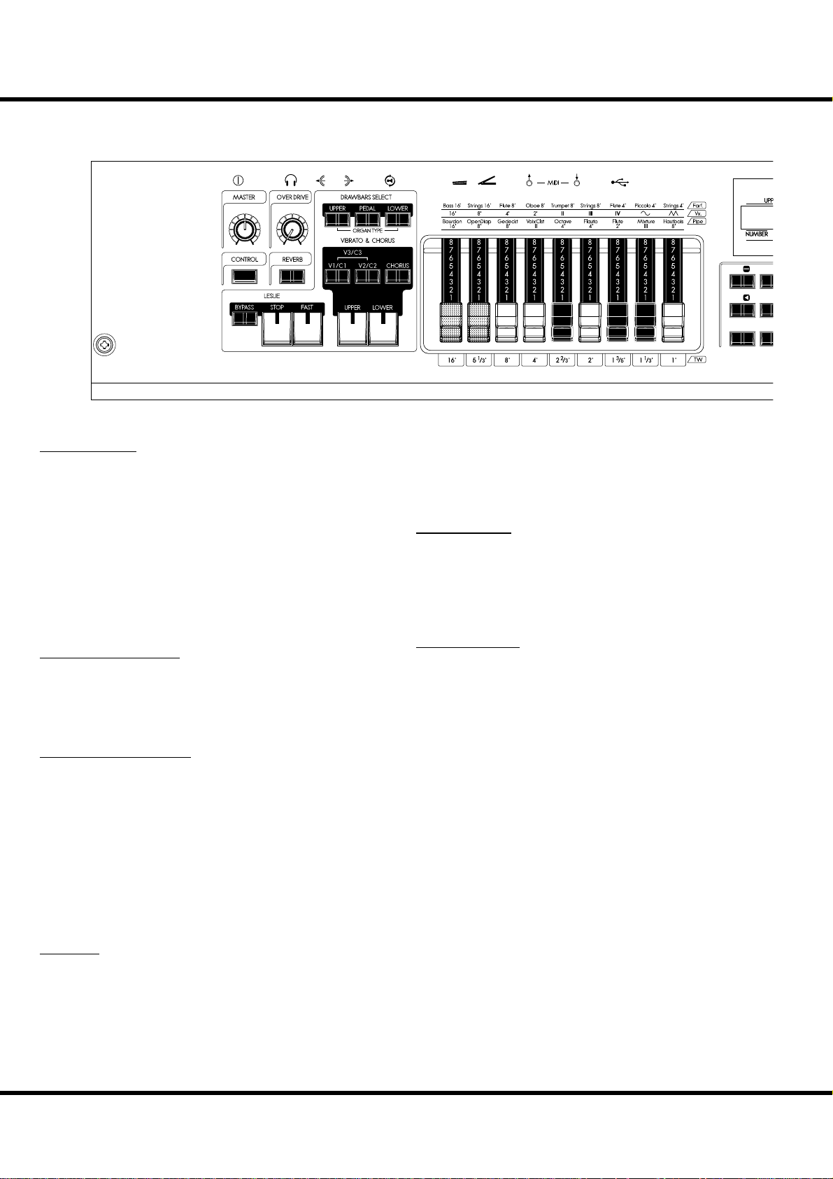
TOP PANEL
NAMES AND FUNCTIONS
❸
❹
❺
❻
AMOUNTVOLUME
❶
❷
❾❿⓫
UPPER LEFT
❶ MASTER VOLUME knob
Controls the total volume. (P. 22)
❷ CONTROL button
Brings the CONTROL window up in the display. Shortcut to
user-programmed parameter, also. (P. 72)
❸ OVERDRIVE AMOUNT knob
Adjusts the amount of the Overdrive eff ect. (P. 48)
❹ REVERB ON button
Switches the Reverb ON/OFF. (P. 50)
DRAWBAR SELECT
❺ UPPER, PEDAL, LOWER buttons
Used to select which division (Upper/Lower/Pedal) the Drawbar settings will aff ect while editing or playing live. e indicator light shows which selector is “live”. (P. 45)
VIBRATO & CHORUS
❻ V1/C1, V2/C2 buttons
Controls the depth of the classic “Vibrato & Chorus” eff ect. 1
is light, 2 is medium, and pressing both buttons selects 3 which
is maximum. (P. 47)
❼ CHORUS button
Toggles between Vibrato and Chorus eff ect. (P. 47)
❽ UPPER, LOWER buttons
Selects which division (or both) receives the Vibrato & Chorus
Eff ect. (P. 47)
❽
❼
21
4
78
⓬
when the light is OFF, it toggles SLOW/FAST(P. 49)
⓫ FAST button
Toggles the modes of the rotors FAST or not. When the light
is ON, it is FAST. (P. 49)
DRAWBARS
⓬ DRAWBARS
ese are for adjusting the basic harmonics of the organ section. e function of each drawbar is diff erent depending on
the keyboard selected (Upper/Lower/Pedal) of type of Organ
(Transistor/Pipe). (P. 38)
PERCUSSION
⓭ ON button
Adds percussion (decay) to the UPPER part. (P. 46)
⓮ THIRD button
Switches the harmonic between second (4´) and third (2 ⅔ ´)
percussion (decay) to the UPPER part. (P. 46)
⓯ FAST button
Switches the decay time of the percussion. (P. 46)
⓰ SOFT button
Switches the percussion volume. (P. 46)
LESLIE
❾ BYPASS button
De-selects the Leslie eff ect and directs the output to the Main
outputs. When the indicator light is ON, the Bypass is engaged. (P. 49)
❿ STOP button
Sets the STOP or SLOW then the [FAST] button is off . When
the light is ON, the [FAST] button toggles STOP/FAST. And
Owner’s Manual
*#1 :-%
Page 11
11
MENU /
⓲
EXIT
VA L U E
⓴
⓳
RECORD
ENTER
⓱
231
5
64
7 8 MANUAL
⓭
⓮⓯⓰
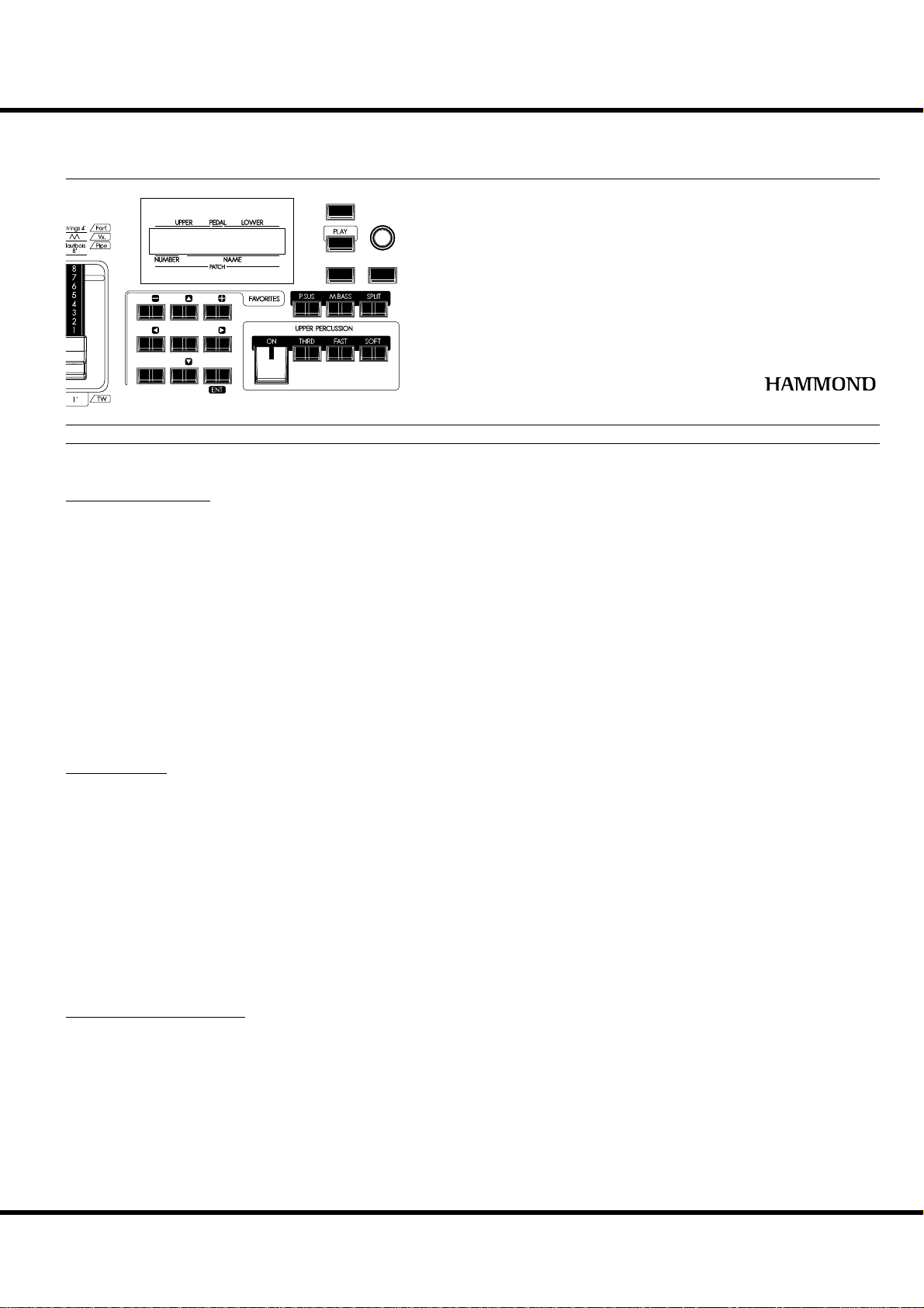
CONTROL PANEL
⓱ DISPLAY
⓲ MENU/EXIT button
Recalls the Menu mode in the display. Also used for returning
to the Menu mode from other function modes. (P. 60)
⓳ PLAY button
Returns to the Play, or basic mode. (P. 59)
⓴ VALUE knob
Increases/Decreases Patch numbers while performing or adjusts
values during editing.
ENTER button
Confi rms the current entry or procedure.
FAVORITES
RECORD button
Enables recording of user-defi nable items. (P. 32)
NUMBER / DIRECTION buttons
Recalls the corresponding Favorites. (P. 24)
In the menu mode and function mode, moves the cursor or
pages (P. 60), increases/decreases the value (P. 62).
MANUAL button
Dismisses any current Patch or Favorite in favor of the current
settings of the control panel. (P. 27)
In the menu mode, this button functions as [ENTER]. (P. 60)
KEYBOARD CONTROL
P. SUS (Pedal SUStain) button
Switches the Pedal Sustain on. (P. 31)
M. BASS (Manual BASS) button
Switches the Manual Bass on. (P. 30)
SPLIT button
Divides the XK-1C keyboard into UPPER and LOWER. (P. 30)
Introduction
Page 12
NAMES AND FUNCTIONS - continued
12
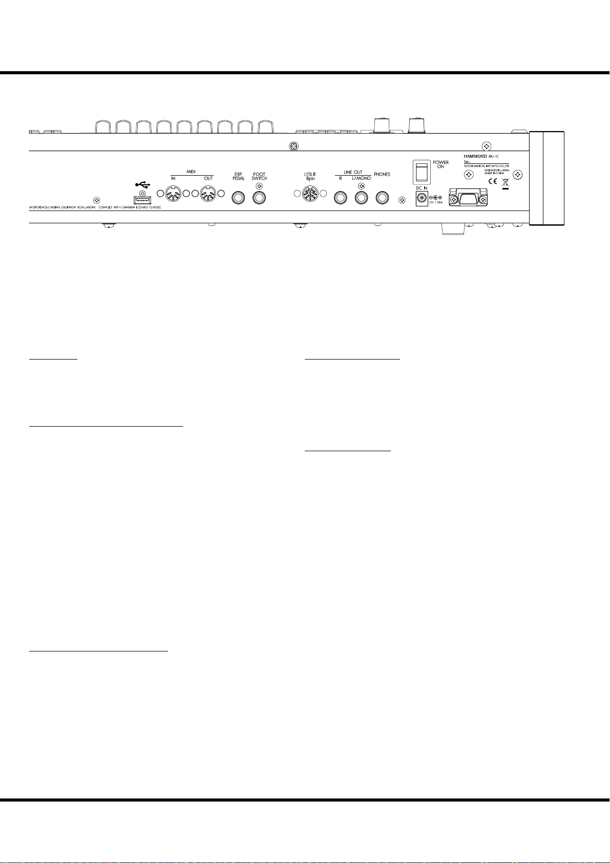
REAR PANEL
USB
FLASH DRIVE
POWER
DC IN jack
Connect the AC adaptor AD3-1250 to this jack.
POWER switch
SOUND OUTPUT TERMINALS
PHONES jack
Connect stereo headphones here.
Connecting Headphones does NOT mute the Line or Leslie
Outputs.
LINE OUT L/MONO jack
LINE OUT R jack
ese are the sound output jacks.
If the connected mixer or monitor speaker is stereophonic, con-
nect both L and R. If monaural, connect only to the L/MONO
terminal (P. 16) and set the Audio Mode at “MONO” (P. 97).
LESLIE 8 PIN jack
Connect a Leslie Speaker equipped with an eight-pin jack here.
When the connection of a external Leslie Speaker is detected,
the on-board Leslie eff ect is disabled to the PHONES jack (30)
and the LINE OUT jacks (31, 32). (P. 17)
MIDI TERMINALS
MIDI OUT jack
MIDI data is output from this jack. (P. 100)
MIDI IN jack
MIDI data received here. From the factory, this terminal is set
to receive channels from a lower manual and pedalboard. (P. 100)
USB TERMINAL
USB FLASH DRIVE jack
is Jack is for connecting a USB Flash drive. (P. 112)
CONTROLLER TERMINALS
FOOT SWITCH jack
Connect the Foot Switch (optional FS-9H etc.) or, Leslie mode
Switch (optional CU-1) here.
Consult (P. 72) to learn the diff erent functions available for the
foot switch.
EXP. PEDAL jack
Connect the Expression Pedal (optional EXP-50 etc.) here.
Controls volume while you are playing. (P. 72)
Owner’s Manual
*#1 :-%
Page 13
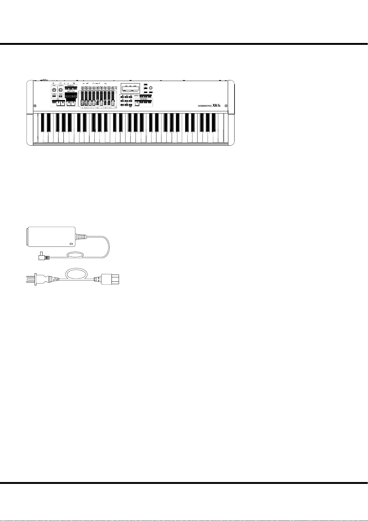
KEYBOARD
AMOUNTVOLUME
231
5
7 8 MANUAL
13
MENU /
EXIT
VALU E
ENTER
RECORD
64
Keyboard
61 waterfall keys, velocity sensitive.
ACCESSORIES
AC adaptor
Supplies power to the instrument - USE ONLY AD3-1250,
DO NOT SUBSTITUTE!
AC cord set
Attaches AC adapter to Wall outlet.
Introduction
Page 14

NAMES AND FUNCTIONS - continued
14
*#1 :-%
Owner’s Manual
Page 15

15
HOOK-UP
Page 16
16
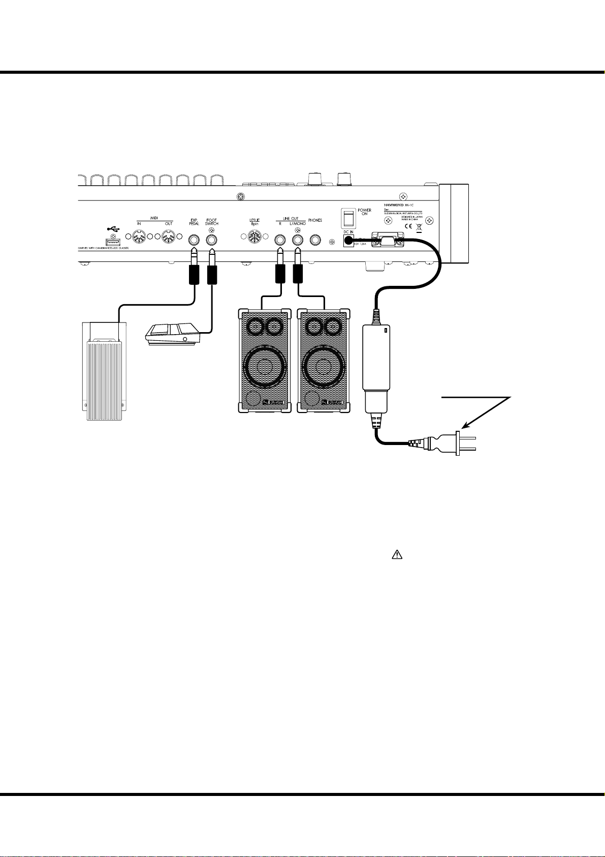
BASIC HOOK-UP
Attach cables and accessories as illustrated.
ere is no on-board amplifi cation or speaker system. An external amp/speaker is
required. When the stereo headphones are connected to the PHONES jack, you can
enjoy playing it or practising by yourself.
Switch this keyboard, and any external equipment OFF before connecting amps or
headphones.
USB
FLASH DRIVE
Foot Switch
FS-9H (optional)
AC adaptor
AD3-1250 (included)
Expression Pedal
(optional)
EXP-50 (optional)
e Expression Pedal and Foot Switch parameters must be set
properly. For details see [CONTROL] (P. 72)
Select Audio Mode for stereo or mono connection (P. 97)
Powered Speakers
to AC outlet
CAUTION
Do not place this unit in direct sun
light, near heat sources, or in a hot
location.
*#1 :-%
Owner’s Manual
Page 17
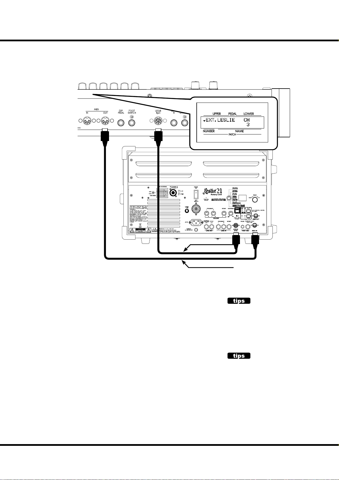
CONNECTING THE LESLIE SPEAKER
An 8-pin type Leslie speaker can be directly connected to this keyboard.
Switch keyboard OFF before connecting the Leslie speaker.
17
8-pin Leslie Cable
MIDI Cable (Optional)
BASIC CONNECTION OF THE LESLIE SPEAKER
Connect the Leslie Speaker #2101, or #2101mk2 and the Leslie 8-PIN jack on this keyboard with the exclusive 8-pin Leslie cable (optional LC-8-7M, not included).
NOTE: The Leslie terminal on this unit is of 8-pin speci cations. Use the Leslie adaptor XLD-811
(optional) to connect a 11-pin spec. Leslie speaker e.g. #122XB.
1. Make the setting of Tone-Wheel organ.
2. Switch “ON” the [BYPASS] button, set the [STATIONARY VOLUME] of the
#2101/mk2 at desired volume.
3. Repeat “ON/OFF” the [BYPASS] button with playing the keyboard, set the [ROTARY VOLUME] of the #2101/mk2 at same volume which you can hear.
MIDI CONTROL OF THE LESLIE SPEAKER
To control the parameters of the Leslie Speaker #2101, #2101mk2 (fi ne adjustment of
the rotor speed or the rise time, etc.):
1. Connect the MIDI OUT of this unit with the MIDI IN of the Leslie speaker with a
MIDI cable.
2. Set the keyboard channel - UPPER and the Leslie MIDI channel to the same channel. (P. 109)
When this unit detects that the Leslie speaker is connected, the Leslie parameters sent
through MIDI from this unit are switched from the XK-1C original to those for the
Leslie speaker.
LESLIE SPEAKERS TO BE CONNECTED
This keyboard is designed to connect with
3 channel Leslie speakers such as the model
#2101. However, it is also possible to connect
1 channel type Leslie speakers such as #3300
sending the stationary channels to the LINE
OUT jacks independently. (P. 80)
LESLIE CHANNEL
3 channel type Leslie speakers are equipped
with a stereo speaker system, independent of
the rotor, to provide direct organ sounds.
A traditional 1-channel Leslie, such as a #122
or #147 has no stationary speaker system, requiring a separate ampli er/speaker for the
direct organ sounds.
Hook-Up
Page 18
18
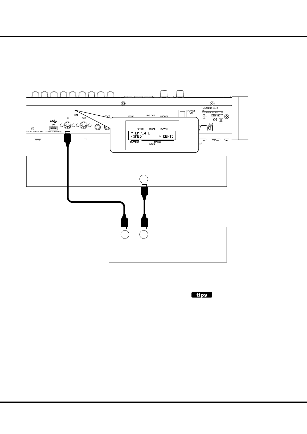
EXPAND THE KEYBOARD
is instrument can be upgraded to dual keyboards by connecting an external MIDI
keyboard and pedalboard.
DUAL KEYBOARD + PEDALBOARD
USB
FLASH DRIVE
MIDI OUT
INOUT
(MERGE)
1. Connect as illustrated above. ere is only one MIDI IN jack onboard this instrument, so a MIDI keyboard with a merge function or a MIDI Merge-box is
necessary for realizing a dual keyboard confi guration.
NOTE: This illustration shows only the keyboard expansion See P. 16 for the basic hook up of
the power source, audio, etc.
2. Turn the XK-1C power ON. en recall the MIDI template “3KBD”. (P. 108)
3. Set the Send channel of the added MIDI keyboard at “2” and that of the MIDI
pedalboard at “3”.
Refer to the operation manual of the added MIDI keyboard and pedalboard, as
required.
MIDI Keyboard
MIDI Pedalboard
HOW MIDI KEYBOARD WORKS?
On the XK-1C, connected MIDI keyboard works
as “LOWER” keyboard when the MIDI template recalled at “3KBD” or “Two Manual”.
RECOMMENDABLE MIDI KEYBOARD
e following HAMMOND MIDI pedalboards (compliant with the XK-1C) are
available from our sales dealers:
MIDI pedalboard XPK-100 (13 keys)
MIDI pedalboard XPK-200 (20 keys), XPK-200L (20 long keys)
ese three models have a MIDI merge function.
Owner’s Manual
*#1 :-%
Page 19
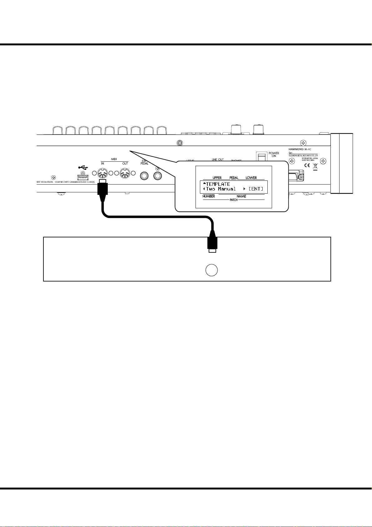
DUAL KEYBOARD
USB
FLASH DRIVE
19
MIDI OUT
1. Connect as illustrated.
NOTE: This illustration shows only the keyboard expansion. See P. 16 for the basic hook up of the
power source, audio, etc.
2. Switch ON the power of this unit. en recall the MIDI template “Two Manual”. (P.
108)
Refer to the operation manual of the added MIDI keyboard as required.
MIDI Keyboard
Hook-Up
Page 20
EXPAND THE KEYBOARD - continued
20
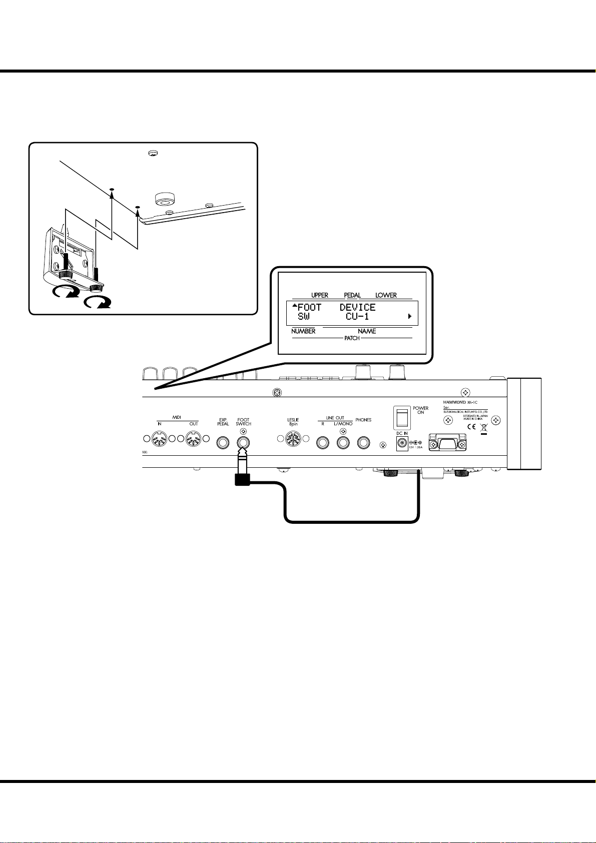
USING CU-1 LESLIE SWITCH
MOUNTING THE CU-1 (optional)
1. Connect the CU-1 to the FOOT SWITCH jack.
NOTE: This illustration shows only the keyboard expansion. See P.16 for the basic hook up of the power
source, audio, etc.
2. Set the CONTROL - FOOT DEVICE” at “CU-1”. (P. 72)
Owner’s Manual
*#1 :-%
Page 21
21
GETTING READY
TO PLAY
Page 22
22
VA
HOW TO POWER ON
AMOUNTVOLUME
UPPER
PEDAL
LOWER
SWITCH ON
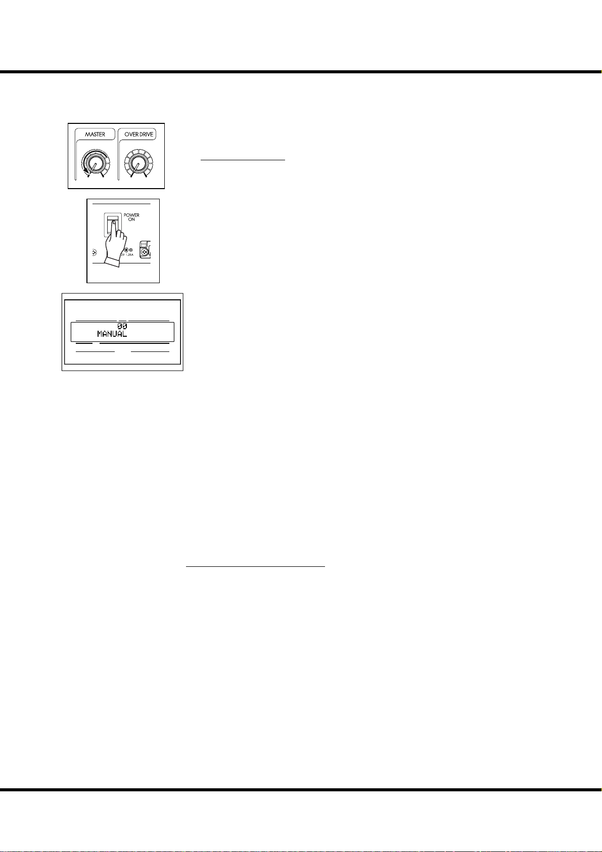
After making the necessary connections, follow the procedures below for powering on
your XK-1C. Please be sure to adhere to the procedure, to prevent malfunction or damage.
PROCEDURES
1. Before switching the power ON, set the [MASTER VOLUME] knob to minimum.
2. Switch ON the [POWER] (on the rear of this keyboard). e Title mode and then
the Play mode are displayed (as illustrated).
For protecting the circuits, the keyboard is designed not to play immediately at
the power on (about 6 seconds).
3. Switch ON the connected amplifi er etc.
4. Play a bit, raising the [MASTER VOLUME] knob to adjust the volume to your
needs.
The [MANUAL] button does not sound in the default settings. Pull some Draw-
bars or select any of the FAVORITE [1] to [8] buttons to test your volume.
5. Adjust the volume of amplifi er etc.
To turn OFF the power, do the above steps in reverse. (Switch OFF the ampli er
etc. rst.)
NUMBER NAME
PATC H
BACK UP
is keyboard “remembers” the unit’s status immediately before the power is turned off ,
returning the unit to that status upon the next power-on.
e status of the default settings are the same as when the [MANUAL] button is depressed.
RESET TO THE FACTORY SETTINGS
To reset all parameters of this keyboard to its default settings, perform the following steps:
OPERATION PROCEDURES
1. Switch the [POWER] of this keyboard off .
2. Switch the [POWER] ON while holding the [RECORD] button.
3. Keep the button depressed until “Loading Default...” is displayed.
4. When the Play mode is displayed, this operation is completed.
*#1 :-%
Owner’s Manual
Page 23
ere are 64 patches loaded in memory from the factory, allowing you to immediately
start playing. You can also create 64 patches of your own.
USER and PRESET
Patches
refer
refer
refer
U1-1
U1-2
U1-3
U1-4
U1-5
P8-6
P8-7
P8-8
“FAVORITE”
buttons
1
23
MANUAL
exclusive
PLAY WITH THE PATCHES
ere are two domains: “USER” and “PRESET” in this key-
First
Second
ird
Fourth
Fih
Mezzo Forte
Forte
Fotissimo
Manual
“VALUE”
knob
in PLAY mode
sequential
select
“P” are not rewritable
board’s Patch memory. You can freely overwrite in the “USER”
domain, but you can not do so in the “PRESET” domain as it
contains the factory settings.
“USER” and “PRESET” are indicated by “U” and “P” respectively.
23
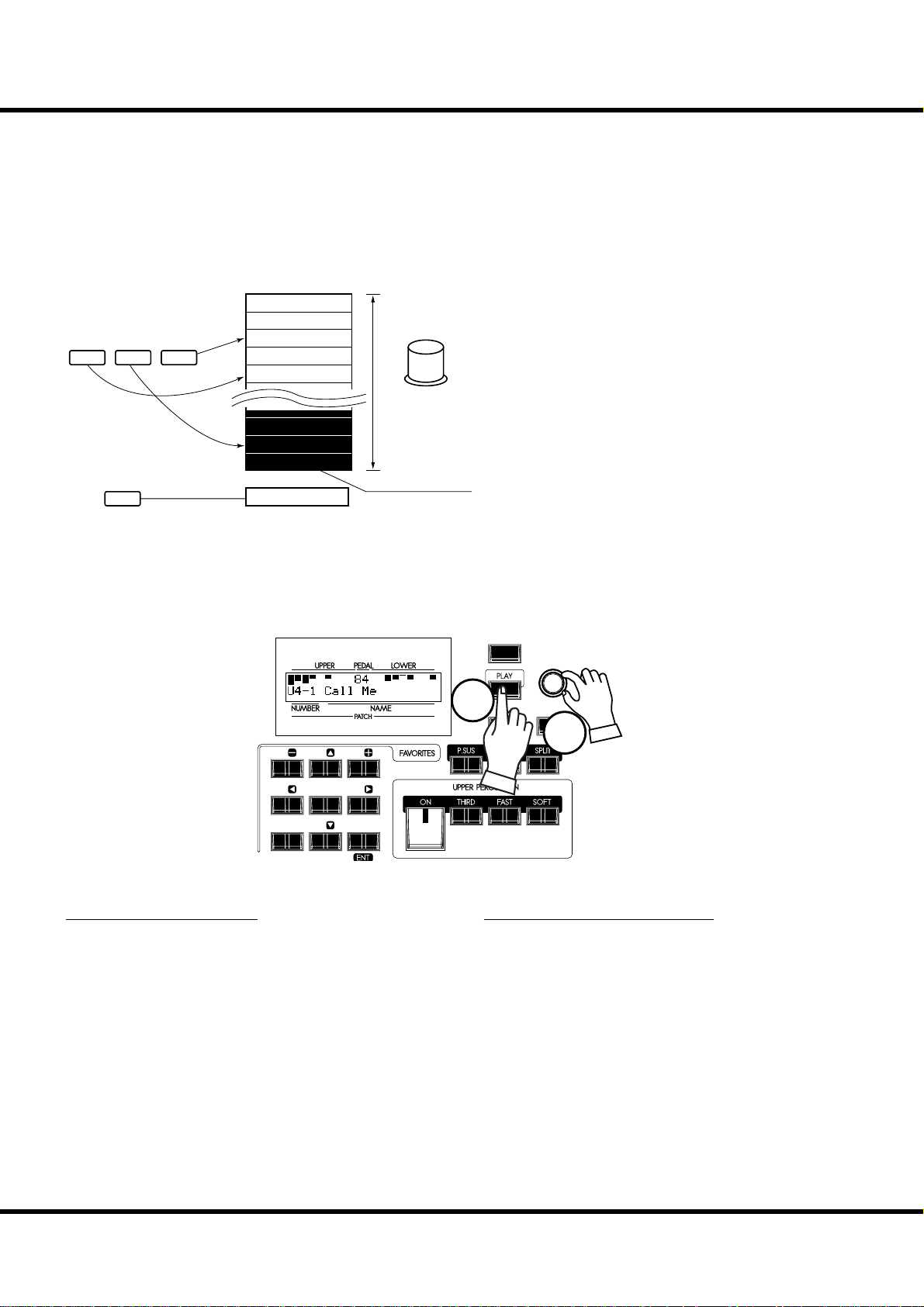
HOW TO CALL A PATCH
Example: Select U4-1.
231
5
7 8 MANUAL
1. GO TO THE PLAY MODE
Select the PLAY button, to enter PLAY mode.
MENU /
EXIT
VA L U E
1
RECORD
ENTER
2
64
2. SELECT THE PATCH NUMBER
Select the patch number U4-1 with the [VALUE] knob. Read
the [PRESET PATCH LIST] (P. 123) in the Appendix for the
preset patch details.
Call various patches to play. When you call patches, not only
the Drawbar registrations but the eff ects such as Leslie, and
reverb also change.
NOTE: You can set which parameters will be recalled (P. 70 #2 to 10).
NOTE: You can set the FAVORITE buttons to select a Patch with direct
key-in (P. 70 #11)
Getting Ready To Play
Page 24
24
REGISTER FAVORITE PATCHES ( FAVORITES)
Patches are selected with the [VALUE] knob. On stage, it is convenient to have your favorite patches available immediately. Here’s how:
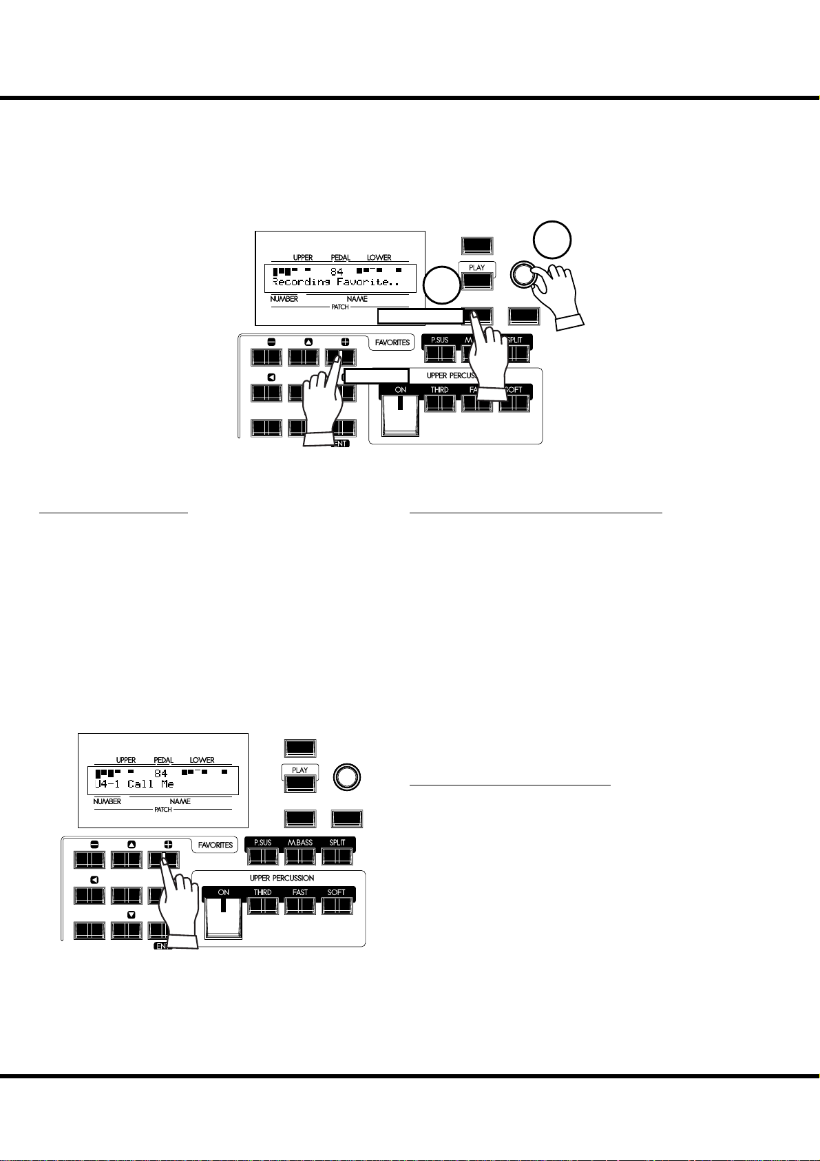
REGISTER PATCHES TO FAVORITES
MENU /
EXIT
VA L U E
1
231
5
64
7 8 MANUAL
1. SELECT THE PATCH
Select the patch you want to register to a favorite button as
shown on the previous page.
Press and hold
Press
2
RECORD
2. SELECT THE BUTTON TO REGISTER
Press the desired Favorite button, while holding down the [RECORD] button. “Recording Favorite..” is displayed
for a moment and the selected Favorite button blinks momentarily. Your favorite is stored. Repeat as desired.
ENTER
HOW TO CALL FAVORITES
MENU /
EXIT
RECORD
231
5
64
7 8 MANUAL
Owner’s Manual
*#1 :-%
VA L U E
ENTER
SELECT THE DESIRED BUTTON
Press the Favorite button you wish to recall. e Favorite button lights and the corresponding patch is called.
Page 25
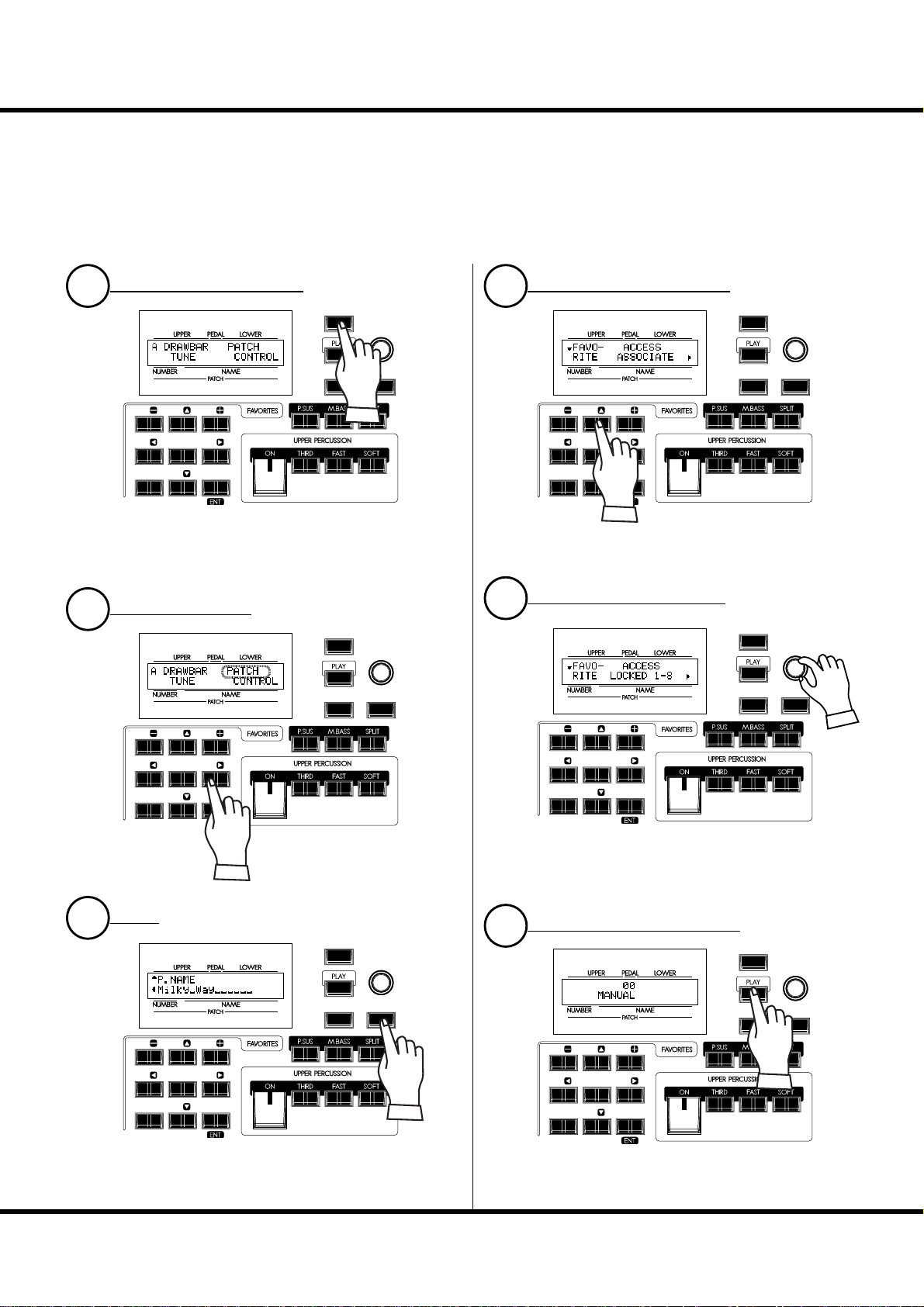
LOCKING PATCHES 1-8
As an alternative to the associated Favorites, You can lock patches 1 through 8, and press
a favorite button while holding the [RECORD] button to record the patch - by following this procedure;
25
LOCATE THE MENU MODE
1
231
5
64
7 8 MANUAL
MENU /
EXIT
RECORD
VA L U E
ENTER
Press the [MENU/EXIT] button. e MENU mode appears.
Repeat-press the menu button until the “A” menu appears (if
necessary)
SELECT THE PATCH
2
231
MENU /
EXIT
RECORD
VA L U E
ENTER
GO TO THE FAVORITE PAGE
4
231
5
64
7 8 MANUAL
MENU /
EXIT
RECORD
VA L U E
ENTER
Press the [S] button twice. e Favorite page appears.
SET VALUE TO LOCKED 1-8
5
MENU /
EXIT
VA L U E
ENTER
RECORD
231
5
64
7 8 MANUAL
Press the [X] buttons to select the
PATCH option (it will blink).
ENTER
3
231
5
64
7 8 MANUAL
MENU /
EXIT
RECORD
VA L U E
ENTER
Press the [ENTER] button to select the patch function mode.
5
64
7 8 MANUAL
Turn the [VALUE] knob and set the value of the item ACCESS
to “LOCKED1-8”.
RETURN TO THE PLAY MODE
6
231
5
64
7 8 MANUAL
MENU /
EXIT
RECORD
VA L U E
ENTER
Press the [PLAY] button. Returning to the PLAY mode.
Getting Ready To Play
Page 26
26
USE THE FOOT CONTROLLERS
Your performance will be more expressive, if you play on the manual using the controllers. You will see on this page how to use the controllers generally used with the electronic
musical instruments. (How to use the exclusive Hammond Organ controllers is shown
on the next page.)
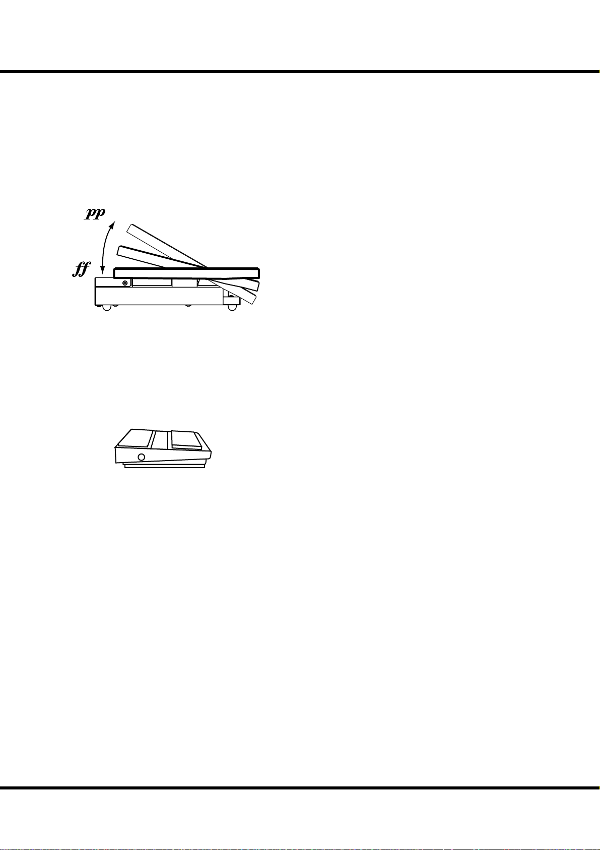
EXPRESSION PEDAL
EXP-50 (optional)
e Expression Pedal controls the overall volume or loudness of
the XK-1C. e further you depress the pedal, the louder the
sound becomes; the more you pull back on the pedal, the softer it.
NOTE: The Expression pedal has speci c parameters to adjust. (P. 26)
FOOT SWITCH
e foot switch can be programmed to various functions. e default setting is [LESLIE S/F ALTERNATE]. Every press toggles,
the mode of the Leslie eff ect between Fast and not.
NOTE: You can change the foot switch assignment. (P. 72)
FS-9H (optional)
*#1 :-%
Owner’s Manual
Page 27
TRY CREATING YOUR OWN SOUND
231
In this section you’ll learn how to create your own sound. In this example, a Classic Jazz
Organ.
SELECT [ MANUAL]
First, select the [MANUAL] button (LED lit).
5
64
7 8 MANUAL
Column: INITIALIZE THE INTERNAL SETTINGS [MANUAL]
e [MANUAL] button makes all the current control panel
settings active, allowing for real-time registration, and the creation of new patches.
NOTE: To return to the previous Patch, press the [MANUAL] button
again (LED o ).
27
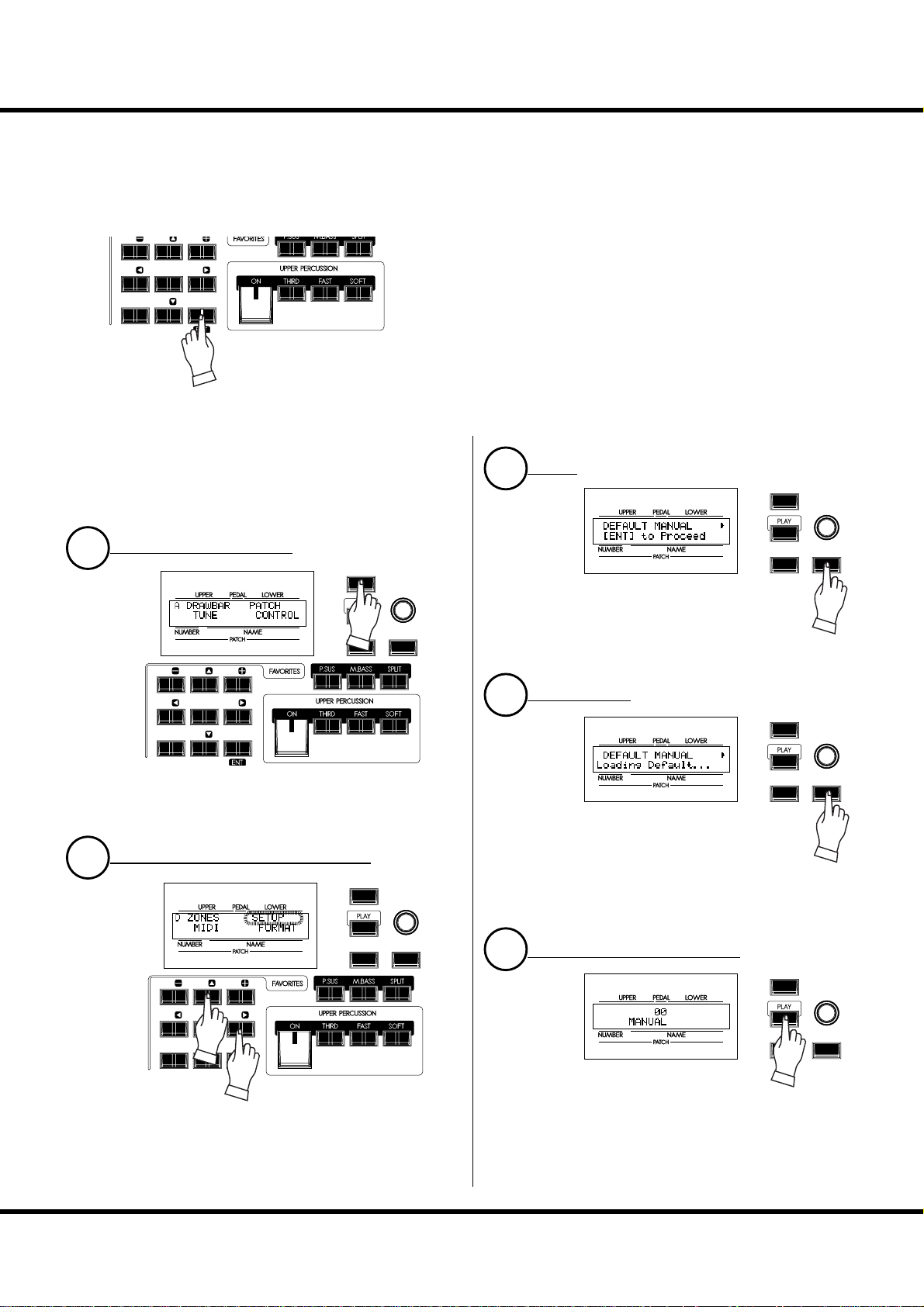
When the MANUAL button is pressed, not only do the current panel settings become active, but the internal settings do
as well. is is the procedure to return them to the DEFAULT
Status.
GO TO THE MENU MODE
1
231
5
64
7 8 MANUAL
MENU /
EXIT
RECORD
VA L U E
ENTER
Select the [MENU/EXIT] button. e Menu mode appears.
If the display is diff erent from the above illustration, select the
[MENU/EXIT] button again.
LOCATE PAGE D, CHOOSE DEFAULT
2
MENU /
EXIT
VA L U E
ENTER
3
MENU /
EXIT
RECORD
Press the [ENTER] button. is brings up the
MANUAL page of the DEFAULT function
mode.
ENTER AGAIN
4
MENU /
EXIT
RECORD
Press the [ENTER] button. e contents of
MANUAL are initialized.
VA L U E
ENTER
VA L U E
ENTER
RECORD
231
5
64
7 8 MANUAL
Press the [S] button 4 times reaching Page D. e ZONE en-
try is blinking.
Press the [X] button twice. e DEFAULT entry is blinking.
ENTER
RETURN TO THE PLAY MODE
5
Press the [PLAY] button. is returns the
XK-1C to the Play mode.
Getting Ready To Play
MENU /
EXIT
RECORD
VA L U E
ENTER
Page 28
E
V
TRY CREATING YOUR OWN SOUND - continued
28
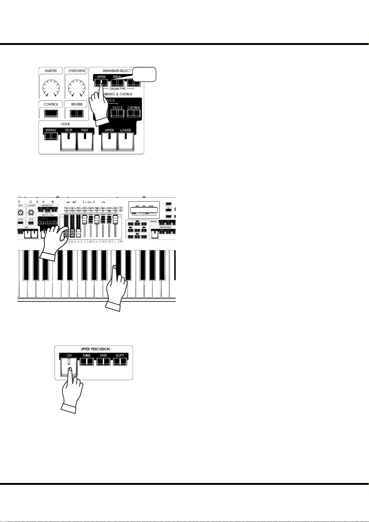
SELECT THE UPPER DRAWBARS
AMOUNTVOLUME
PULL OUT DRAWBARS
AMOUNTVOLUME
“On”
13
5
7 MANUAL
MENU /
RECORD
e DRAWBARS SELECT buttons are for selecting which
part the Drawbars will control written below step.
NOTE: What is a “PART”? (p. 30)
Select [UPPER]. is is the basic Organ Part, the one used
most frequently.
EXIT
Pull out Drawbars to your taste. You can monitor your selections easily while playing the keyboard (the UPPER keyboard
if keyboards are extended).
e Drawbars make the fundamental organ sound of this keyboard. e tone changes in relation to how far the Drawbars
are “pulled”.
e volume of each sound is greatest when the Drawbar is
pulled out all the way, and null when fully pushed back. e
Drawbars are arranged so that the pitches grow higher from
left to right.
For this example, pull the 16´, 5 ⅓ ´ and 8´ Drawbars to “8”
(all the way out).
NOTE: You can change the sound character of the Drawbars. (P. 68)
NOTE: The present registration is displayed in the Play mode. (P. 59)
ADD THE TOUCH-RESPONSE PERCUSSION
Hammond’s Touch-Response Percussion adds a distinctive attack to the Tone Wheel/Drawbar sounds. is percussion is
not like a Drum or Cymbal, but closer to an xylophone or marimba. [PERCUSSION] is available only on the UPPER part.
To enable the percussion, turn the [ON] button on.
ere are two choices of Percussion Pitch. One sounds an oc-
tave above the note played (“Second”), and another sounds a
“twelfth” above. (“ ird”) - When the [THIRD] light is off
“Second” is selected.
e [FAST] button quickens the decay of the Percussion voice
and [SOFT] reduces the volume of the Percussion Voice.
For this example select all of the Percussion buttons [ON],
[THIRD], [FAST], [SOFT].
NOTE: You can ne-tune the percussion parameters to your taste. (P.
76)
*#1 :-%
Owner’s Manual
Page 29
ADD EFFECTS TO THE ORGAN SECTION
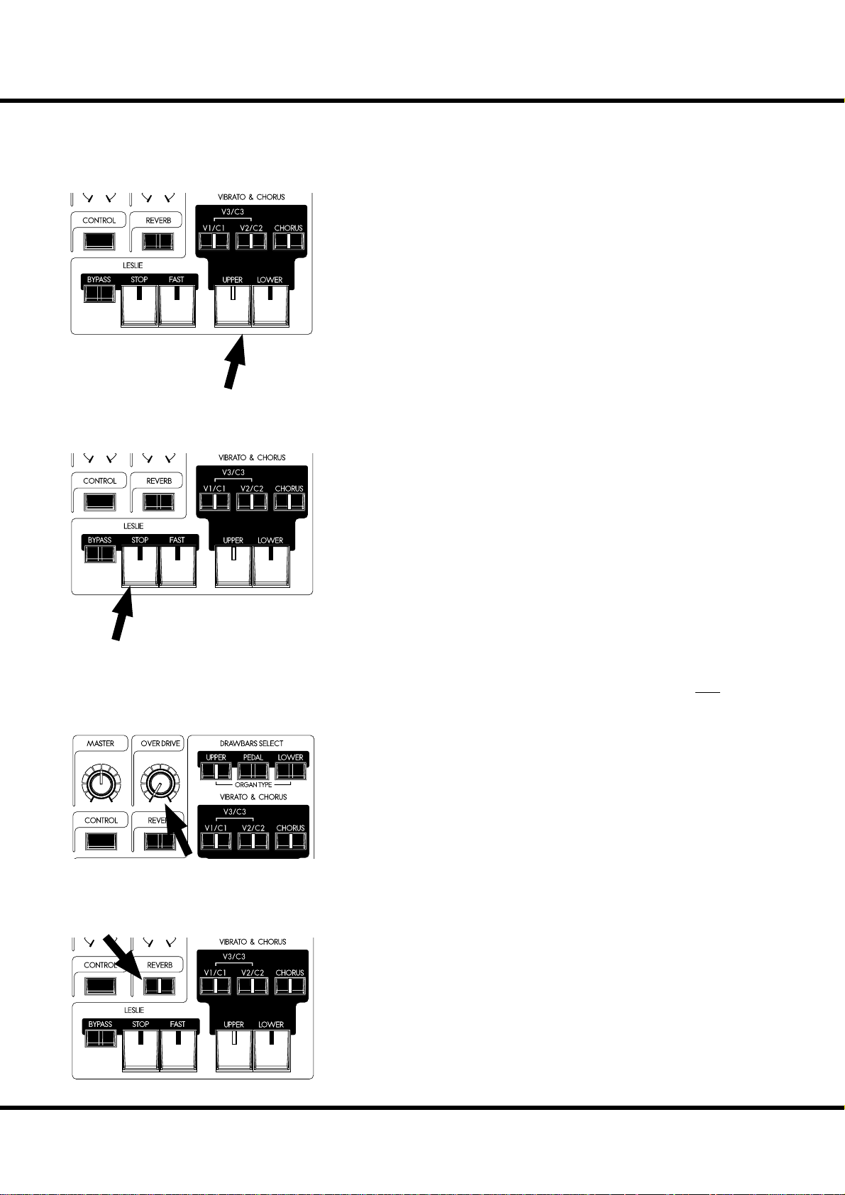
VIBRATO & CHORUS
Adding the Classic Hammond Vibrato & Chorus to the sound.
[UPPER], [LOWER] buttons
Switches the Vibrato & Chorus eff ect ON/OFF. When ON, the light illuminates.
[V1/C2], [V2/C2] buttons
ese set the depth of the Vibrato eff ect. When both buttons are selected, the depth
becomes maximum as V3/C3.
[CHORUS] button
is button changes the Vibrato to Chorus eff ect - Also changing the V1/V2/V3 to
C1/C2/C3. When the Chorus eff ect is engaged the button light illuminates.
NOTE: You can ne-tune the speed of Vibrato/Chorus. (P. 77)
For this example, switch ALL of the Vibrato & Chorus buttons to “ON” (except
[LOWER]).
LESLIE
e LESLIE eff ect is the famous “Moving and Swirling” sound provided by rotating
horns and speakers, but executed here in the Digital realm.
[FAST] button
is button toggles the mode of the rotor to fast or not. When the light is ON, it is
FAST, and when OFF, not.
[STOP] button
is button sets the mode when the [FAST] button is off . When the light is ON, it is
STOP, and when OFF, it is SLOW.
[BYPASS] button
To Engage the Leslie eff ect, press the [BYPASS] button turning the light OFF.
NOTE: These controls perform the same functions when a external Leslie speaker is connect-
ed via the 8 pin plug.
NOTE: You can ne-tune the parameters of the on-board Leslie e ect etc. (P. 78)
For this example, let’s set the status of all Leslie buttons lights to OFF.
OVERDRIVE
e overdrive section adds warmth at low settings, and “grit” or distortion at higher.
AMOUNTVOLUME
[AMOUNT] knob
Adjusts the amount of Overdrive. e amount increases as you rotate the knob clockwise. It is bypassed when you rotate the knob at minimum.
29
REVERB
e Reverb makes the concert-hall eff ect.
[ON] button
Turns the Reverb eff ect ON.
Getting Ready To Play
Page 30
TRY CREATING YOUR OWN SOUND - continued
30
WHAT IS A “ PART”?
Each “PART” is equivalent to a player in a band or an orchestra. e 3 Parts here
are expressed in Organ terms: UPPER. LOWER, and PEDAL. ese parts can be
individually played with diff erent sounds.
e XK-1C has a single keyboard. Plural parts are available simultaneously, by splitting the keyboards or expanding them using a MIDI keyboard.
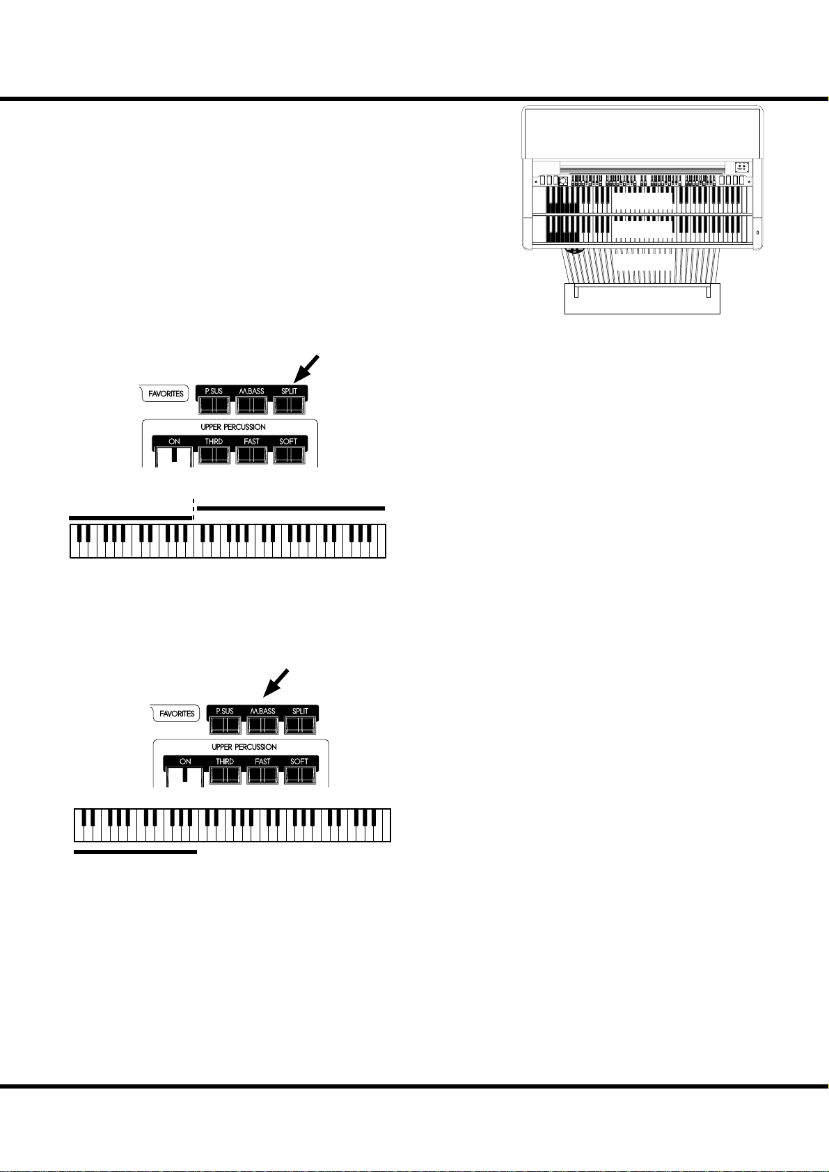
KEYBOARD SPLIT
e XK-1C has only 1 manual, but it can be split and will respond
as if it were a 2 manual instrument.
[SPLIT] button
To use the Split function, press the [SPLIT] button and the light
will go ON. e default setting split is at the middle B/C.
NOTE: You can change the split point (dividing note) and octave. (P. 106)
NOTE: The Split function is disabled when a second MIDI Keyboard is
added. (P. 108)
Right of the split point is referred to as: UPPER and the left side
LOWER. Percussion does not function on the LOWER part.
ere is no SPLIT function available when the keyboard is extended.
Lower
Split Point
Upper
NORMAL OFF OFF
VOLUME
SOFT
FAST
THIRD
SOFT
ON
VIBRATO
VIBRATO
VIBRATO
SWELL
GREAT
AND
CHORUS
ON
ON
PERCUSSION
PERCUSSION
PERCUSSION
HARMONIC
PERCUSSION
DECAY
VOLUME
SELECTOR
SLOW
SECOND
NORMAL
OFF
UPPER
LOWER
PEDAL
MANUAL BASS
Manual Bass
You can play the Pedal voices using the lowest notes of the keyboard
(the LOWER keyboard if keyboard is extended) using MANUAL
BASS.
[M. BASS] button
To use the Manual Bass function, press the [M. BASS] button and
the light will go ON. e Pedal/Bass sound is heard in conjunction with the lowest note being played, on the manual keyboard
till that time.
In order to not interfere with the melody performance, the default Manual Bass limit point is set to sound up to, and including
middle “B”.
NOTE: The Manual Bass can be set to play in Lowest, Polyphonic, and
Chord modes (P. 106 #1). You can change the playing range of the
Manual Bass (the upper limit) (P. 106 #2).
NOTE: When the XK-1C is expanded to 2 manual, the Manual Bass func-
tion appears on the LOWER keyboard. (P. 108)
e Manual Bass plays the PEDAL part and its sound is controlled
by the [PEDAL] Drawbars. is is originated from the style of
playing bass on the pedal keyboard of a 3 keyboard type organ.
You can use both the manual bass and the split at the same time.
Making it possible to play the bass + chord + melody together.
NOTE: Jazz organists add a distinctive rhythm by “thumping” one or
more pedals in time to their playing. You can simulate this technique without having a pedalboard by assigning a pedal note to
a foot switch via a CONTROL parameter. See (P. 72).
*#1 :-%
Owner’s Manual
Page 31

PEDAL SUSTAIN
31
A popular eff ect for organ bass is “PEDAL SUSTAIN”, which adds
a smooth decay reminiscent of a string bass.
[PEDAL SUSTAIN]
To engage the pedal sustain, press the [P. SUS] button and the light
will go ON. When you release your foot from the pedalboard (or
release the key on the keyboard - when using manual bass), the
PEDAL part decays smoothly.
NOTE: You can adjust the sustain time of the Pedal Sustain. (P. 69 #16)
Getting Ready To Play
Page 32

TRY CREATING YOUR OWN SOUND - continued
32
RECORD THE PATCH TO MEMORY
All the previous settings can be recorded to any Patch within the range of U1-1 to U8-8.
Example: RECORD TO U3-2
MENU /
1
2
231
5
64
7 8 MANUAL
EXIT
RECORD
MENU /
EXIT
VA L U E
ENTER
VA L U E
Press the [RECORD] button.
A question “Which patch do you want to record?” appears in
the display.
Select the patch number, this time U3-2, to record, using the
[VALUE] knob.
3
RECORD
MENU /
EXIT
RECORD
ENTER
VA L U E
ENTER
Press the [ENTER] button.
e Patch Number is decided and “Recording Patch” is
displayed. When the recording process completes, the display
returns to the previous mode.
e recorded patch is automatically selected.
NOTE: User created patch data is not lost when the power is turned
o and/or disconnected.
*#1 :-%
Owner’s Manual
Page 33

33
SETTING UP
Page 34

34
SOUND ENGINE STRUCTURE
Pedalboard
Pedal
Drawbars
Pedal
Virtual
Tonewheel Set
Lower Keyboard
Lower
Drawbars
Lower&Upper
Virtual
Tonewheel Set
Upper Keyboard
Percussion
Upper
Drawbars
Expression
Vibrato & Chorus
TC & Equalizer
Multi Effect
Leslie on Reverb
Leslie
Simulator
Exp.
Reverb
Overdrive
Master
Equalizer
Line Out
Leslie 8Pin
*#1 :-%
Owner’s Manual
Phones
Page 35

To fully utilizing this unit, read the following detailed explanations about the various functions for creating music.
ORGAN SECTION
TONE-WHEELS
e sound source or “engine” of the classic Hammond Organ are the electro-magnetic
Tone-Wheel Generators. On this keyboard, the Tone Wheel engine is replicated digitally.
While the power is on, each of the 96 virtual Tone-Wheels keeps oscillating as they did
in the vintage Hammond Organs.
KEYS
e tone signals created with the 96 virtual Tone-Wheels are “switched” at the keys.
To each key the signals corresponding to the pitch and harmonics (for example, 9 sets on
the manual keyboard) are distributed, and when you touch or release a key, the switch
connects or cuts the tone signals, in the same manner as a faucet controls water fl ow.
DRAWBARS
Each Drawbar represents a fundamental harmonic. Each bar adjusts the volume of each
harmonic. ere are 9 drawbars corresponding to 9 diff erent harmonics.
TOUCH-RESPONSE PERCUSSION
e Percussion creates a distinctive attack on the UPPER part.
VIBRATO & CHORUS
e Vibrato & Chorus gives depth and richness to the organ sound by slightly varying
the pitch (Vibrato), or doubling the voice by mixing the original sound, with a duplicate,
slightly detuned one (Chorus).
35
TONE-WHEEL SETS
The Tone-Wheel Sets are divided into the
Manuals and the Pedal Part. This is to give the
Pedal Part the Decay (= the sound gradually
fading out while pressing the key) or Sustain
E ect. (= the sound gradually fading out after
the key is released).
HARMONICS
Harmonic is a pitch of a di erent ratio to a certain pitch; for example, the one octave higher
C to the middle C. The more Harmonics, the
brighter and richer sound is obtained.
OVERDRIVE
e Overdrive creates distortion as if an amplifi er was being driven beyond its limits.
MULTI-EFFECTS
e Multi-Eff ects create various eff ects such as tremolo and Wah.
EQUALIZER, LESLIE, REVERB
Other on-board Eff ects are as follows: an Equalizer for sculpting the tonal response, a
Leslie eff ect for rotary speaker eff ects, and Reverb.
( e on-board Leslie eff ect is disengaged when a external Leslie speaker is connected to
the 8-pin terminal.)
MASTER EQUALIZER
e signal is routed through the Master Equalizer. Allowing you to tailor your sound
for the provided venue, amp, sound system or recording. e settings are not saved in
patch memory.
Setting Up
Page 36

36
ORGAN SECTION
ORGAN TYPE
ere are various “Organ” types: the Hammond Tone-Wheel organs used in everywhere rock, jazz, and Gospel, the transistor organ frequently heard in pop music of
‘60’s. Classical pipe organ used in classical music or church services. All organs have
characteristic sounds.
is keyboard will sound like the types of organ you choose.
TONE-WHEELS (BType1, BType2, Mellow)
ese are various types of Hammond Organs’ characteristic tone wheels. e Hammond Organ’s original purpose was to duplicate the pipe organ, however, they became famous for producing a unique sound of their own.
e BType1 and BType2 have the B-3/C-3’s traditional Tone-Wheel sounds. e
BType2 has more wow-fl utter and leakage noise.
e Mellow is not a Tone-Wheel, if strictly speaking. It replicates the fi rst-generation
non-mechanical Transistor Hammond Tone Generators like the GT-7 and Concord.
TRANSISTOR ( Vx, Farf)
After the transistor became generally used, the light weight organs were introduced
(such as Ace Tone TOP-6 etc.) using the transistor circuit instead of the tone wheels
or tubes. e circuit system is diff erent from maker to maker or model by model. We
have replicated 2 representative types here.
e Vx is a type to combine the triangle wave and square wave with several footages.
e Farf is one to combine the sound wave forms coming through plural fi lters with
the tablet switch.
PIPE
e Church/Classical Pipe Organ uses thousands of individual pipes driven by wind
from a blower to create its sound. e name of the stops tells you which wind instrument is duplicated.
You can create other sounds by combining diff erent organ Stops, in the same way
Drawbars are used on this keyboard.
Owner’s Manual
*#1 :-%
Page 37

Column: SELECTING THE ORGAN TYPES
Use the control panel for switching the organ types.
Example: Switching the manual part to “Pipe”
37
1
2
AMOUNTVOLUME
Press the [UPPER] and [LOWER] buttons together. e
DRAWBAR function mode is displayed and the organ type
(“BType1” etc.) of the manual keyboard presently selected
blinks.
MENU /
EXIT
VA L U E
VA L U E
ENTER
Select “Pipe” with the [VALUE] knob. e pipe organ sounds
MENU /
EXIT
RECORD
when you play the keyboard.
RECORD
ENTER
3
MENU /
EXIT
RECORD
VA L U E
To return to the PLAY mode, press the [PLAY] button.
ENTER
Setting Up
Page 38

38
HARMONIC DRAWBARS™
e 9 Drawbars on this keyboard are used to create the basic “Hammond” sounds.
Each Drawbar is marked with the register numbers 1 - 8 along the fl at part of the
Drawbar. When the Drawbars are fully pushed in, no sound is heard; as the Drawbars
are “pulled” the volume of that harmonic increases.
When recalling a patch, the drawbars’ “positions” will change internally, but not
physically. When a drawbar is moved, the setting will “snap” to that drawbar’s current
position.
DRAWBARS (ON TONE-WHEEL ORGAN)
16' 8' 4'
51/3'
22/3'
2'
13/5'11/3'
1'
Middle “C”
e pitch of each Drawbar is as shown above, when the middle C is depressed. e
footage marked (´) legend in front of each Drawbar is derived from the corresponding length of pipes of a pipe organ.
e numbers 1 - 8 on the “bar” portion of each Drawbar indicate the volume of the
sound to be produced as well as the guide to remember Drawbar settings.
Pull the fundamental (8´), the third harmonic (2⅔ ´) plus the fi fth harmonic (1⁄´)
Drawbars out completely and play the keyboard. Notice how the sound resembles
a clarinet.
If you push the 8´ Drawbar half-way, you’ll notice the sound becomes more highpitched and a bit “harder”. Now pull the 8´ Drawbar back out fully and push the
2⅔ ´ and 1⁄´ in halfway. Notice how the sound becomes mellower.
Experiment with the Drawbars to obtain your own personal favorite sounds.
In the case of the Tone-Wheel Organ, refer the correspondence
between each bar and the footage to the “TW” row in front of
the Drawbars.
Owner’s Manual
*#1 :-%
DRAWBAR RESISTRATION
The lengths of the pulled out Drawbars.
Page 39

DRAWBARS FOR THE UPPER AND LOWER PARTS
39
WHITE DRAWBARS
16' 8' 4'
51/3'
BLACK DRAWBARS
16' 8' 4'
51/3'
22/3'
22/3'
2'
2'
13/5'11/3'
13/5'11/3'
1'
In each Drawbar set, the white Drawbar on the left side (8´)
provides the fundamental sound. e remaining white Drawbars sound higher by the octave as you move to the right.
1'
e sounds of the black Drawbars play an important role in
building rich tones. eir pitches are fi fth and third to the fundamental. ese harmonics add complexity to the tone.
BROWN DRAWBARS
16' 8' 4'
51/3'
22/3'
2'
13/5'11/3'
1'
DRAWBARS TO USE ON THE PEDAL
1/3
16' 8' 4'
5
'
2/3
2
'
3/5
2'
1
1/3
'1
1'
'
e two brown Drawbars on the far left give depth and richness
to the sound. e left 16´ is one octave lower than the 8´, and
5⅓ ´ is the third harmonic of the 16´ fundamental. Normally,
the tones are built on the 8’ fundamental, but, if you want to
add depth to the tone or to expand the playing range by one
octave lower, build your tones on the 16´ fundamental.
e Pedalboard plays the bass line and uses the 16´ and 8´
Drawbars. e fi rst Pedal Drawbar produces a tone at 16´ pitch
for a deep foundation bass, while the second Pedal Drawbar
produces a tone at 8´ pitch, or one octave higher.
e registration of the Pedal part appears in the center of the
display. 16´ on the left and 8´ on the right.
Setting Up
Page 40
HARMONIC DRAWBARS™ - continued
40
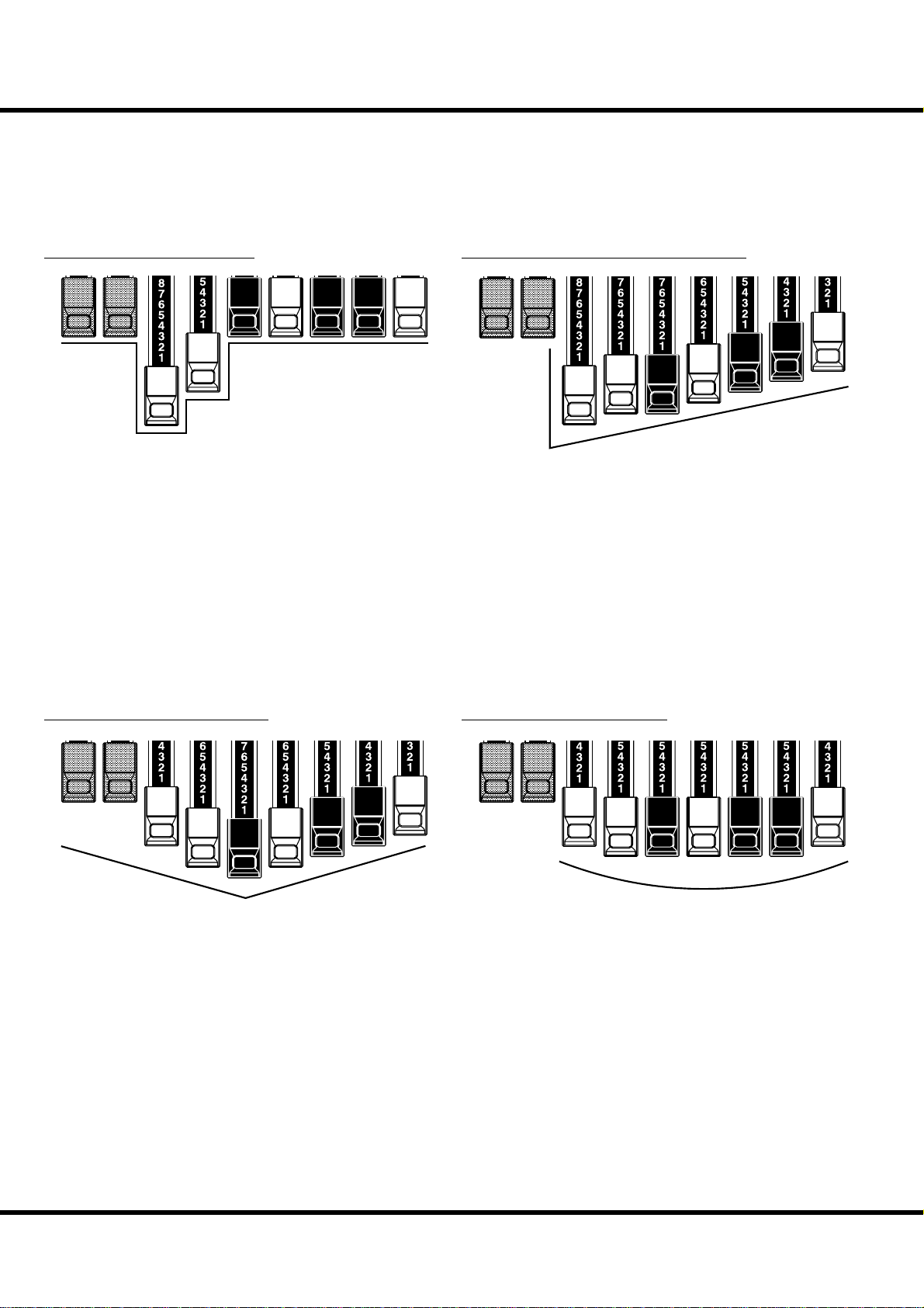
DRAWBAR REGISTRATION PATTERNS
e Drawbar Registration is matched by digits. It is easy to remember the typical
combinations of the 9 Drawbars by their forms.
e Drawbar Registrations are grouped into the following 4 patterns:
Flute family (2 step pattern)
16' 8' 4'
51/3'
Accompaniment Flute 8´ I .............. 00 8460 000
Accompaniment Flute 8´ II ............. 00 3220 000
Accompaniment Flute 8´ III ........... 00 8600 000
Chorus of Flutes 16´ ....................... 80 8605 002
Orchestral Flute 8´ .......................... 00 3831 000
Piccolo 2´ ........................................ 00 0006 003
Stopped Flute 8´ .............................00 5020 000
Tibia 8´ ........................................... 00 7030 000
Tibia 4´ ........................................... 00 0700 030
Tibia ( eater) 16´ .......................... 80 8605 004
Wooden Open Flute 8´ ................... 00 8840 000
22/3'
2'
13/5'11/3'
Diapason family (check mark pattern)
1'
16' 8' 4'
51/3'
Accomp. Diapason 8´ ...................... 00 8874 210
Chorus Diapason 8´ ........................ 00 8686 310
Diapason 8´ .................................... 00 7785 321
Echo Diapason 8´ ........................... 00 4434 210
Harmonic Diapason 16´ ................. 85 8524 100
Harmonic Diapason 8´ ................... 00 8877 760
Harmonic Diapason 4´ ................... 00 0606 045
Horn Diapason 8´ ........................... 00 8887 480
Open Diapason 8´ .......................... 01 8866 430
Solo Diapason ................................. 01 8855 331
Wood Diapason 8´ .......................... 00 7754 321
22/3'
2'
13/5'11/3'
1'
Reed family (triangle pattern)
16' 8' 4'
51/3'
Bassoon 16´ .................................... 44 7000 000
Clarinet 8´ ...................................... 00 6070 540
English Horn 8´ .............................. 00 3682 210
Flugel Horn 8´ ................................ 00 5777 530
French Horn ................................... 00 7654 321
Kinura 8´ ........................................ 00 0172 786
Oboe 8´ .......................................... 00 4764 210
Trombone 8´ ................................... 01 8777 530
Trumpet 8´...................................... 00 6788 650
Tuba Sonora 8´ ............................... 02 7788 640
Vox Humana 8´ ..............................00 4720 123
22/3'
2'
13/5'11/3'
String family (bow pattern)
2
1'
16' 8' 4'
51/3'
Cello 8´ ........................................... 00 3564 534
Dulciana 8´ ..................................... 00 7770 000
Gamba 8´ I ..................................... 00 3484 443
Gemshorn 8´ ................................... 00 4741 321
Orchestral String 8´......................... 00 1464 321
Salicional 8´ .................................... 00 2453 321
Solo Viola 8´ ................................... 00 2474 341
Solo Violin 8´.................................. 00 3654 324
Viola da Gamba 8´ .......................... 00 2465 432
Violina 4´ ........................................ 00 0103 064
Violone 16´ ..................................... 26 3431 000
/
2
2'
3'
13/5'11/3'
1'
*#1 :-%
Owner’s Manual
Page 41

MODERN DRAWBAR REGISTRATIONS
e Drawbar registrations introduced on the previous page are typically for classical music.
ey were created at the dawn of the Hammond Organ, when it was intended to sound
like a pipe or church organ. Later on, as the Hammond Organ spread throughout Jazz,
Pop, Rock and (especially) Gospel music, Some timeless registrations become common.
Jazz Bluesy
16' 8' 4'
51/3'
22/3'
2'
13/5'11/3'
ON ON ON ON
1'
16' 8' 4'
51/3'
22/3'
2'
13/5'11/3'
41
1'
Groovy & Funky Max Power
16' 8' 4'
16' 8' 4'
51/3'
22/3'
2'
13/5'11/3'
1'
51/3'
22/3'
2'
13/5'11/3'
1'
APPLICATION OF PERCUSSION
When Percussion is used, the sound of the 1´
Drawbar is cancelled. As it was on the Vintage
B-3. A trick is to keep the 1’ drawbar fully out,
and then turn the percussion on and o as you
play for a instant change in sound. Try it!
Setting Up
Page 42

HARMONIC DRAWBARS™ - continued
42
DRAWBARS ( Vx)
16´ 4´ 2´
Oscillators
8´
16´
8´
4´
2´
II
III
IV
II
Filter
III
IV
at Middle “C”
to output
e original British Vx type organ was
equipped with Drawbars, but the function
was diff erent from that of the Hammond
Organ. e vintage arrangement has been
re-created here.
Each of the 4 bars on the left functions similarly to the Hammond Organ. II, III and
IV on the right are “Mixture” drawbars that
sound plural pitches.
e 2 Drawbars on the right are a mini
mixer controlling the mellow voice “ ” or
bright voice “ ” as in the vintage combo
organ.
Each or both of the two right-hand Drawbars must be pulled in some combination to
hear sound in the Vx type.
FOOTAGE
The markings, “8’, 4’” etc., indicate the lengths of
pipes corresponding to their pitch. The common
term for these numbers are “footages”.
For example, 8’ means that a pipe of 8’ in length
sounds, the lowest C on a standard 5 octave organ
keyboard.
If the organ type is set to Vx, refer to the
“Vx” row on the other side of the Drawbars
for the correspondence between each bar
and the footage.
*#1 :-%
Owner’s Manual
Page 43

DRAWBARS ( Farf)
43
Bass 16´
Strings 16´
Flute 8´
Oscillators
16
8
4
Trumpet 8´
Oboe 8´
Filters
Bass 16´
Strings 16´
Flute 8´
Oboe 8´
Trumpet 8´
Strings 8´
Flute 4´
Piccolo 4´
Strings 4´
Strings 8´
to output
Strings 4´
Piccolo 4´
Flute 4´
at Middle “C”
e original Italian Farf type organ was
tablet-equipped with diff erent sounds at
various footages. On this keyboard the operation is made with Drawbars instead of
tablets.
At the same footage, the tablets gives grow
brighter in sound as you progress to the
right. e names “Flute”, “Strings”, etc. are
general descriptions and do not refl ect the
tonalities or characteristics of the real instruments.
When using the Farf type organ, refer to the
“Farf” row on the other side of the Drawbars for the correspondence between each
bar and the footage.
Setting Up
Page 44
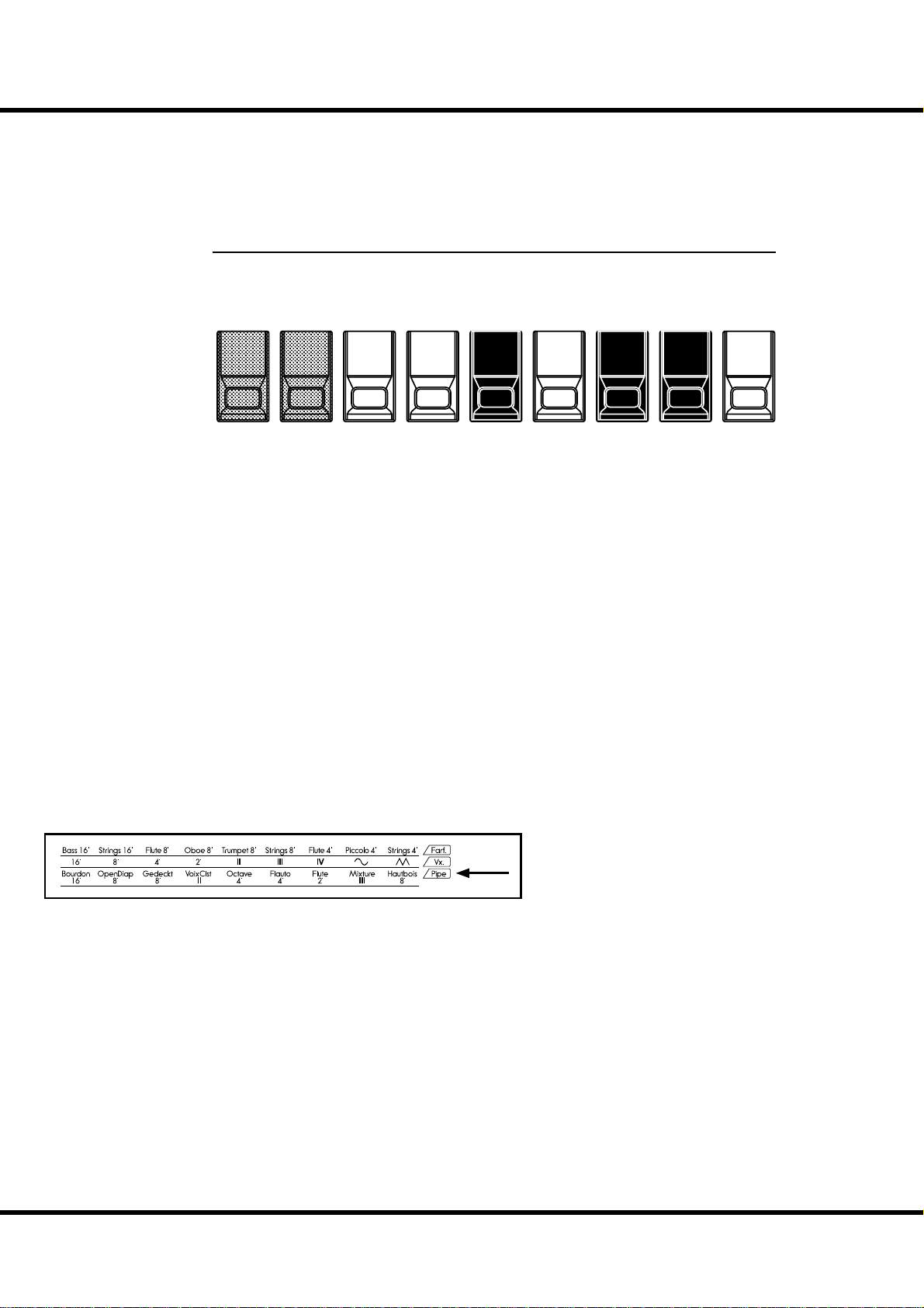
HARMONIC DRAWBARS™ - continued
44
DRAWBARS ( PIPE)
Open
UPPER:
LOWER:
Bourdon
Principal
Sub Bass 16´
PEDAL:
Gedeckt 8´
When using the PIPE organ type, the stops are registered through the Drawbars, and
follow the classic organ layout left to right as follows: Flue,Mixture and Reed.
On the UPPER and LOWER parts, each Drawbar corresponds with a stop of the
pipe organ.
On the PEDAL part, two stops sound with one Drawbar.
NOTE: The e ects - Vibrato & Chorus, Leslie, Overdrive - are not available on the Pipe type
voices.
Diapason
16´
Principal
16´
+
Gedeckt
8´
8´
8´
Melodia
8´
Principal Chorus
+
Mixture IV
Viole
CelesteIIOctave
4´
Rohr
Flute8´Prestant4´Flute
Flauto
Dolce4´Flute2´Mixture
4´
Super
Octave
2´
III
Mixture
IV
Hautbois
8´
Trom-
pette
8´
*#1 :-%
Owner’s Manual
If the organ type is Pipe, refer to the “Pipe”
row on the other side of the Drawbars for
the correspondence between each bar and
the stop.
Page 45

DRAWBAR SELECT
ASSIGN DRAWBARS TO PARTS
Physical Drawbars
On
UPPER PEDAL LOWER
Press
E
a
n
Disable
D
i
45
Upper Registration
le
b
Lower Registration
sa
b
l
e
Pedal Registration
is keyboard has 3 parts; UPPER, LOWER and PEDAL. e
UPPER part is normally used, and, when you want to sound
the LOWER, PEDAL, use the Split / Manual Bass Function or
connect a MIDI keyboard and/or Pedalboard and assign each
part.
One set of drawbars is used to register all three parts individually, using the Drawbar select buttons.
All LEDs are “Off”
UPPER PEDAL LOWER
Physical Drawbars
Press again
If you de-select a drawbar button, the instant control of the
Drawbars for that part is suspended. You can “pre-set” a registration, however (covered in next section).
e Drawbars select buttons are [UPPER], [PEDAL] and
[LOWER]. e button you choose, sends the registration commands to proper part of the sound engine.
Upper Registration
e
l
b
a
Dis
Disable
D
D
D
i
i
i
s
s
sa
Lower Registration
a
a
b
b
b
l
l
l
e
e
e
Pedal Registration
MATCH THE REGISTRATION TO DRAWBARS
Physical Drawbars
not equal
Upper Registration Upper Registration
When you recall a patch, the Drawbar registration of the recorded patch is heard, instead of the physical Drawbar setting.
If you move any Drawbar, its position takes precedence over
the recorded registration, although the recorded preset is not
altered.
If you wish to switch to the physical Drawbar setting, Press
Blink “On”
UPPER PEDAL LOWER UPPER PEDAL LOWER
Press and hold
and hold the corresponding button ([UPPER], [PEDAL] or
[LOWER]) in the Drawbar select until the light blinks then
release it. e physical registration now becomes “current”.
Physical Drawbars
equal
Setting Up
Page 46

46
PERCUSSION
One of the most important features introduced with the Classic B-3 was “TouchResponse” Percussion, which added a distinctive and bright percussive highlight to
the top of the Drawbar tone.
[ON] button
Switches the percussion “ON” and “OFF”.
To engage, press the [ON] button. (light on).
[THIRD] button
Switch the harmonic of the percussion.
When this button is OFF, the 2nd harmonic speaks at the same pitch as the 4´ Draw-
bar (Analogous to the “Second” setting on a B-3).
e 3rd harmonic tone speaks at the same pitch as the 2 ⅔ ´ Drawbar (Analogous to
the “ ird” setting on a B-3). To select, press the [THIRD] button (light on).
[ FAST] button
When this button is OFF (LED not lit) the percussion tone will decay (decrease in
volume) slowly like a bell. When it is “ON” (LED is lit) the percussion tone will
decay rapidly like a xylophone.
[SOFT] button
is reduces the volume of the Percussion.
When the LED is OFF, it is “NORMAL”. If you press the [SOFT] button (LED is
lit on), the Percussion level is “SOFT”.
NOTE: Percussion is available on 3 Organ types; BType1, BType2 and Mellow.
NOTE: You can ne-tune the parameters of the Percussion (P. 76).
DECAY
On the piano, the sound gradually fades out even
if you keep touching the key. It is called Decay. The
violin sound, on the contrary, keeps sounding at a
certain volume. It is called Sustain.
1´ DRAWBAR CANCEL
As on the Vintage Hammond B-3, the 1´ Tone-Wheel Drawbar is inoperative when
the Percussion is engaged.
NOTE: If you wish the 1´ Drawbar to remain operative, you can change the parameter. (P. 76)
Owner’s Manual
*#1 :-%
Page 47

VIBRATO & CHORUS
e Hammond Vibrato & Chorus is another hallmark of the Classic Hammond
sound. Vibrato alters the pitch slightly, as a violinist, singer, or guitarist might do.
Chorus combines a slightly detuned signal with the original for a lush tone.
[UPPER] button
Pressing [UPPER] button “ON” (LED lit) will turn the Vibrato & Chorus eff ect on for
the UPPER Drawbars.
[LOWER] button
Pressing [UPPER] button “ON” (LED lit) will turn the Vibrato & Chorus eff ect on for
the LOWER Drawbars.
[V1/C1], [V2/C2] button
ese buttons are for setting the depth of the Vibrato & Chorus eff ects.
V1 (C1): V1 (C1), light vibrato (chorus)
V2 (C2): V2 (C2), vibrato (chorus) of standard depth.
V1+V2 (C1+C2): V3 (C3), deepest vibrato (chorus)
NOTE: While the power is on, the Vibrato and/or Chorus button LED’s will always be on. The ef-
fect will not be active unless the UPPER or LOWER switches are pressed (LED on).
[CHORUS] button
e CHORUS eff ect combines a slightly detuned signal with the original.
Press this button to switch the Vibrato to Chorus (LED lit).
47
STATUS CHART OF EACH BUTTON
BUTTON MODE
V1/C1 V2/C2 CHORUS Effect
On O O V1
O On O V2
On On O V3
On O On C1
O On On C2
On On On C3
NOTE: Vibrato & Chorus is available on 5 Organ types; BType1, BType2, Mellow, Vx and Farf.
NOTE: The speed etc. of the Vibrato & Chorus e ects can be ne-tuned. (P. 77)
NOTE: The Vibrato & Chorus e ects on this keyboard come from a virtual model of the mechani-
cal scanner as rst used on the vintage B-3. It operates in the same manner, albeit in the
digital realm. (no moving parts)
Setting Up
Page 48

48
OVERDRIVE
Overdrive simulates the eff ect of pushing an amplifi er beyond its normal limits to
achieve a more aggressive sound.
By changing the drive amount, various sounds are obtained from an unclipped
warmth to a hard distortion.
ME
[OVERDRIVE AMOUNT] knob
Adjusts the amount of the Overdrive eff ect.
Rotating the knob at the end of counter-clockwise, the eff ect is “Off ”.
Rotating the knob clockwise increases the depth of the eff ect.
NOTE: Drawbar Overdrive is available on 5 Organ types; BType1, BType2, Mellow, Vx and
Far f.
NOTE: You can ne-tune the overdrive sound. (P. 86)
AMOUNT
*#1 :-%
Owner’s Manual
Page 49

LESLIE
e rotating sound of the LESLIE Speaker is the natural partner of the Hammond Organ. A Digital version is built-in to the XK-1C; and the controls will
also function with a connected external Leslie speaker.
[ FAST] button
Toggles the mode of the rotor by two steps. Every press switches
the status. When the light is ON, the mode is FAST, and when it
is OFF, it is not.
[ STOP] button
To toggle the FAST and SLOW when you pressed the [FAST] button, press this button and the light OFF.
To toggle the FAST and STOP when you pressed the [FAST] button, press this button and the light ON.
[ BYPASS] button
When the light is OFF, the sound is output from the rotary channel (Leslie eff ect).
To bypass the Leslie eff ect, press this button and the light will go
ON. Regardless of the status of the [FAST], [STOP] buttons, the
sound is output from the stationary channel.
NOTE: Leslie E ect is available except Pipe type.
NOTE: You can ne-tune the parameters of the Leslie e ect. (P. 78)
STATUS CHART OF EACH BUTTON
BUTTON MODE
BYPASS STOP FAST CH=1
O O On Fast
O O O Slow
O On On Fast
O On O Stop
On On On Fast
On On O Stop
On O On Fast
On O O Slow
49
CH=3,
on-board
Leslie effect
Bypass
Diagram of 3 channel Leslie Speaker
Horn
Rotor
Stationary
Speaker
Amplifier
800Hz
Bass
Rotor
Horn
Driver
Woofer
WHAT IS THE LESLIE EFFECT?
The Leslie Speaker was invented by Donald Leslie in
1941 to make the Hammond Organ sound like a Theatre Pipe Organ. Using motor-driven rotating horns and
ba es, Leslie’s invention gave the organ a rich and
moving tone, which quickly became it’s own unforgettable sound.
In its basic form, the Leslie Speaker has an built-in
ampli er and two rotors; the “Horn Rotor” for treble
and the “Bass Rotor” for bass which are each fed by a
custom-designed driver/speaker. The combination of
the two utilizes the “Doppler E ect” to give the unique
Leslie “swirling” sound.
Some models have not only rotors but also a xed
speaker. The circuit for sending the sound to the rotor
is called the “Rotary Channel”, and that for the xed
speaker is called the “Stationary Channel”.
The Digital Leslie on-board the XK-1C employs all the
proprietary concepts used in the physical speakers, but
realizes them in the digital realm. It is recommended
that you run the Main Outputs “in stereo” to get the fullest e ect.
Setting Up
Page 50

50
REVERB, MULTI-EFFECTS
e XK-1C has on-board Digital Reverb and Multi-Eff ects to enhance the performance.
REVERB
AMOUNTVOLUME
[REVERB ON] button
To engage the Reverb, press this button and the light will go ON.
NOTE: You can ne-tune the depth, time etc. of the Reverb. (P.95)
MULTI-EFFECTS
e XK-1C has various multi-eff ects such as Tremolo, Wah-Wah and so on. See the
“OD/EFF” paragraph (P. 86) for detail.
*#1 :-%
Owner’s Manual
Page 51

MANUAL BASS, PEDAL SUSTAIN
e PEDAL part may be played on the low part of the keyboard using the MANUAL
BASS function.
A popular option for playing the Pedals or Manual Bass is Pedal Sustain, which allows
the Pedal voice to smoothly decay upon release, much in the manner of a string bass.
[M. BASS] button
To engage the Manual Bass function, press the [M. BASS] button (light ON).
If you have the keyboard SPLIT, the Manual Bass will sound in tandem with the chosen
LOWER registration.
If you have a MIDI keyboard attached as the LOWER keyboard, the MANUAL BASS
will appear there, on the lowest notes.
e default range of the MANUAL BASS is up to the middle “B”.
NOTE: You can change the highest note range of the MANUAL BASS (P. 106 #2).
NOTE: You can select the MANUAL BASS play chords or only the lowest note (P. 106 #1).
[P. SUS] button
To engage the PEDAL SUSTAIN, press the [P. SUS] button (light ON).
After releasing a key on Pedal keyboard (if attached) or, releasing a Manual key while
using the Manual Bass function, the sound will slowly fade, or decay.
NOTE: You can control the decay time of the Pedal Sustain (P. 69 #16).
51
COUPLER
Like the Manual Bass, the function to set a keyboard to play two keyboards together is called
“COUPLER”.
Setting Up
Page 52

52
KEYBOARD SPLIT, OCTAVE SHIFT, TRANSPOSE
e XK-1C normal range is the UPPER Keyboard. A split is optional to place the
LOWER keyboard voices on the left side of the single keyboard.
e keyboard can be shifted up or down one octave to facilitate easier play.
[SPLIT] button
Press to split the keyboard, (light ON).
NOTE: You can set the split point. (P. 106)
To raise or lower the octave of the keyboard, see the “ZONES” paragraph (P. 106).
To transpose the keyboard, see the “TUNE” paragraph (P. 71).
*#1 :-%
Owner’s Manual
Page 53

e settings (including registrations) you have prepared can be recorded to User Patches.
USER AND PRESET
P AT C H
53
“FAVORITE”
buttons
1
23
MANUAL
exclusive
refer
refer
refer
Patches
First
U1-1
Second
U1-2
ird
U1-3
Fourth
U1-4
Fih
U1-5
November
U8-6
December
U8-7
“User” ends
U8-8
Preset begins
P1-1
Monday
P1-2
Tuesday
P1-3
Mezzo Forte
P8-6
Forte
P8-7
Fortissimo
P8-8
Manual
“VALUE”
knob
in PLAY mode
sequential
select
“P” are not rewritable
ere are 64 USER and 64 PRESET Patches as illustrated. e “User” Patch are overwrite capable. e “Preset” Patches are not.
To call the Patch, select the Patch Number
with the [VALUE] knob in the Play mode
(P. 23).
To record the present setting to the patch,
fi rst give a name to it and designate the
patch number before recording the patch
(next page).
e [MANUAL] button on the right bottom of the favorites shifts the focus to the
current settings of the top panel, and the current internal settings. It is used as a starting point for writing your own patches, or for the musician who prefers to register
“by hand” instead of using patches.
PATCH LOAD
Only the Drawbar registrations of each keyboard
were recorded to the preset of the B-3/C-3. But
many more parameters than the Drawbar registrations are recorded to the patches on this keyboard.
If you wish to keep the “traditional” style of registration (Drawbars only), Select the proper parameters in “Patch Load”. (P. 70)
Setting Up
Page 54

PATCH - continued
54
NAME THE PRESENT SETTING
GO TO THE MENU MODE
1
Press the [MENU/EXIT] button.
Menu mode will be displayed.
GO TO PAGE A
2
231
MENU /
EXIT
RECORD
MENU /
EXIT
RECORD
VA L U E
ENTER
VA L U E
ENTER
GO TO PATCH FUNCTION MODE
4
MENU /
EXIT
RECORD
Press [ENTER] and go to PATCH function mode.
INPUT NAME
5
MENU /
EXIT
RECORD
VA L U E
ENTER
VA L U E
ENTER
5
64
7 8 MANUAL
If Page A is not displayed, go to Page A by pressing [T] button.
SELECT THE “PATCH”
3
MENU /
EXIT
VA L U E
RECORD
231
5
64
ENTER
231
5
64
7 8 MANUAL
You can enter a name using up to 15 letters.
[W],[X] buttons: Moves the cursor.
[VALUE] knob: Selects letters.
e Characters available are the Capital and small English Alphabet, symbols and digits.
e name input here is not captured until you record the patch
(as explained on the next page).
7 8 MANUAL
Press [X] button twice and move the cursor to “PATCH”.
Owner’s Manual
*#1 :-%
Page 55

RECORD TO THE PATCH
Example: RECORD TO “U3-2”
GIVE THE NAME
1
PRESS THE [RECORD] BUTTON
2
MENU /
EXIT
55
Enter the name of your Patch. (P. 54)
VA L U E
SELECT THE PATCH NUMBER
3
PRESS [ENTER]
4
RECORD
MENU /
EXIT
RECORD
MENU /
EXIT
RECORD
ENTER
VA L U E
ENTER
VA L U E
ENTER
Press the [RECORD] button. e Record mode is displayed.
Select the patch number you wish to record with the [VALUE]
knob ( is time select U3-2).
Press the [ENTER] button. e patch is confi rmed and is displayed as follows for a few seconds:
Recording Patch...
When the recording is completed, the display returns to the
previous one.
NOTE: The recorded patch data is retained if the power is switched
o or disconnected.
Setting Up
Page 56

56
*#1 :-%
Owner’s Manual
Page 57

57
USING THE
CONTROL PANEL
Page 58
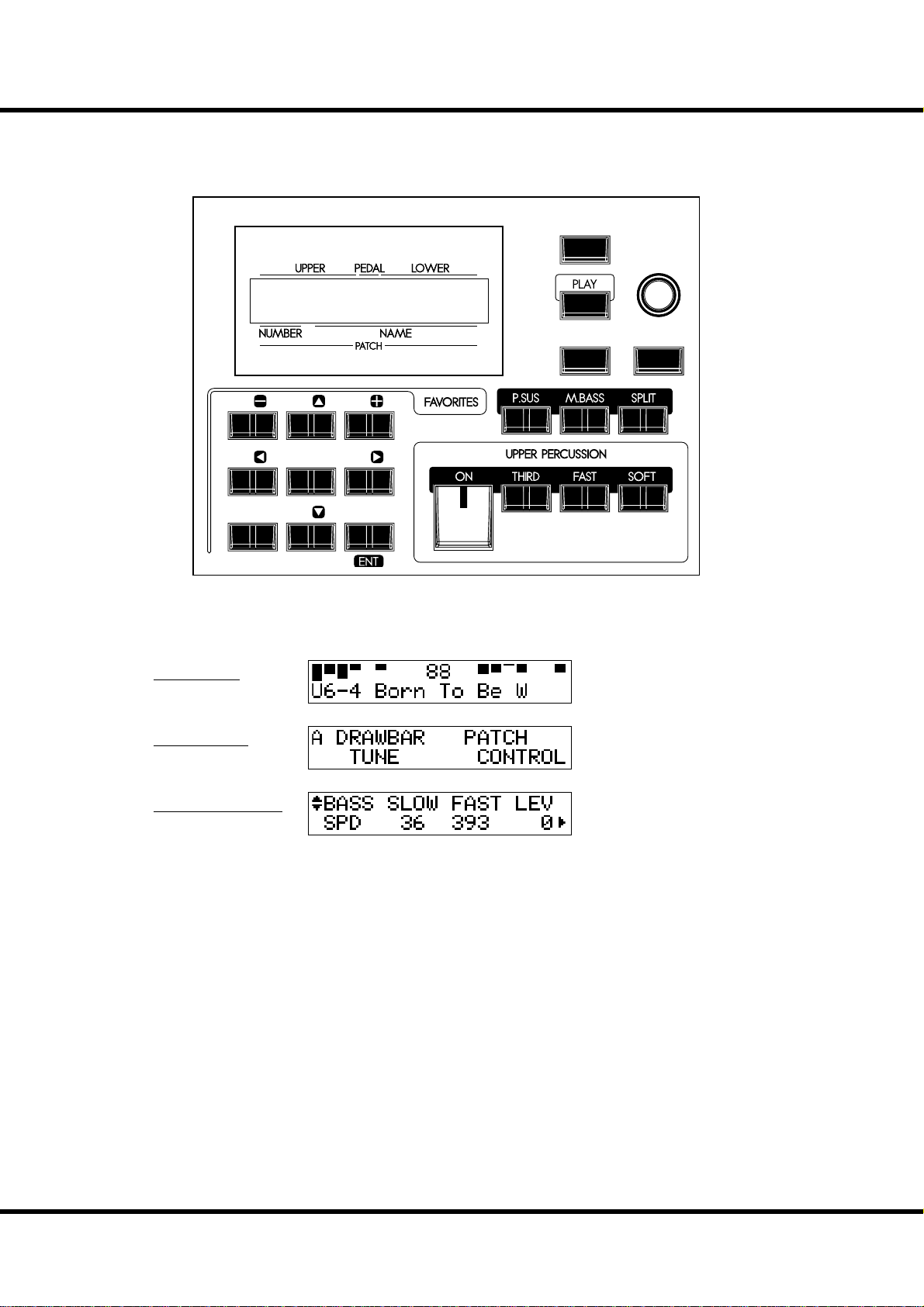
58
WHAT YOU CAN DO ON THE CONTROL PANEL
Your access to deep-editing the XK-1C. All of the parameters and all of the controls not covered by the top panel knobs and switches are here.
MENU /
EXIT
VA LU E
RECORD
231
5
7 8 MANUAL
e available modes are, basically “PLAY”, “MENU” and “FUNCTION”. See how to
read them and how to use the buttons on the next pages.
64
PLAY mode
MENU mode
ENTER
FUNCTION mode
*#1 :-%
Owner’s Manual
Page 59

PLAY MODE
e Play mode is basic for all operations. All information necessary for ordinary performance
is displayed here.
To locate this mode
1. “Play mode” is the default mode at power-up.
2. If the Play mode is not displayed, touch the [PLAY] button.
HOW TO READ THE DISPLAY
Drawbar Registration
UPPER / PEDAL / LOWER
Display of Registration
(Bars)
59
Patch
Display of Registration
(Digits)
BUTTON OPERATION IN THIS MODE
MENU /
EXIT
PLAY
e two PLAY modes, for displaying the
Registration are toggled every time the
[PLAY] button pressed.
Display the Menu mode.
Select the Patch
VA LU E
RECORD
Switch the two Play mode types.
ENTER
Using the Control Panel
Page 60

60
MENU MODE
e menu mode provides a directory of all the various functions.
To locate this mode:
Press the [MENU/EXIT] button.
ere are many pages functions available to edit. A menu page has up to four items.
Search for the item you wish to edit using the direction buttons, then press the [ENTER]
button and enter each Function mode.
HOW TO READ THE DISPLAY
Page Items
BUTTON OPERATION IN THIS MODE
Return to the Play mode.
231
5
7 8 MANUAL
64
Select the item in the page.
Enter the selected Function mode.
Move the page.
MENU /
EXIT
RECORD
VA LU E
ENTER
Select the item, also.
Enter the selected Function mode.
*#1 :-%
Owner’s Manual
Page 61

MENU AND THE CONTENTS
PAGE A
1. DRAWBAR
Sets the parameters for the Drawbars of each part. (P. 68)
2. TUNE
Set the tuning and transpose of the entire keyboard. (P. 71)
3. PATCH
Patch naming, Parameter Load and Assignment of Favorites. (P. 70)
4. CONTROL
For adjusting the controllers, such as the Expression Pedal and Foot Switch. (P. 72)
PAGE B
1. CUST. TW
For custom setting of the tone wheel sets of the Lower and Upper part. (P. 72)
2. PERCUSS
For custom setting the percussion parameters. (P. 76)
3. VIB & CHO
For custom setting the characteristics of the Vibrato & Chorus. (P. 77)
4. LESLIE
For adjusting the on-board Leslie eff ect and sets the external Leslie speaker settings. (P. 78)
61
PAGE C
1. PIPE
Adjust the characteristics of the Pipe stops here. (P. 84)
2. O. D./EFF
Adjust the Overdrive and the Multi-Eff ects here. (P. 86)
3. EQUALIZ
For setting the parameters of the Patch and Master Equalizer. (P. 94)
4. REVERB
For setting the Reverb parameters. (P. 95)
PAGE D
1. ZONE
For setting the Internal Zone and External Zones. (P. 106)
2. MIDI
For setting the basic MIDI operations. (P. 108)
3. SETUP
For saving/loading the set-up to/from a USB Flash drive. (P. 112)
4. FORMAT
For initializing the USB Flash drive. (P. 113)
PAGE E
1. DEFAULT
For returning to the various factory default settings. (P. 96)
2. SYSTEM
For setting the System Parameters and displaying the System information. (P. 97)
Using the Control Panel
Page 62

62
FUNCTION MODE
ese modes are for selecting and controlling the function.
All modes can be navigated the same way.
HOW TO READ THE DISPLAY
There is another page above (or below)
this page.
PARAMETER
(ITEM) NAME
PAGE NAME
VALUE
CURSOR
( ashing VALUE)
Shows there is another page on the right (or the
left) of this page.
CURSOR
In this example the ashing “cursor” indicates
the value of the fast speed of the Leslie.
BUTTON OPERATION IN THIS MODE
Adjust the value of the cursor
location.
231
5
7 8 MANUAL
64
Return to the MENU mode / Exits the current mode.
Return to the PLAY mode.
MENU /
EXIT
VA LU E
RECORD
ENTER
Adjust the value of the cursor
location.
Move the page up or down.
*#1 :-%
Owner’s Manual
Move the cursor on the page. The cursor
goes to the edge of the mode, and, if there
is another page on the right or the left,
moves to that page.
Page 63

SHORT CUT TO FUNCTION MODE
Each button on the top panel has a built in shortcut-making programming and editing easier.
Pressing and holding any of the buttons on the top panel automatically jumps the
display to the related function menu item.
EXAMPLE OF OPERATION:
LOCATE THE PERCUSSION FUNCTION MODE
Press and hold
63
If you wish to edit the percussion settings, press and hold either of the [ON], [THIRD], [FAST], or [SOFT] buttons, and
the display will immediately jump to the percussion function
mode. is is called “SHORT CUT”.
In the next chapter, you will see which button is used for a
particular “SHORT CUT”.
NOTE: Changing the length of time until display jump when button
is held. (P. 74)
REGISTER THE PAGES YOU FREQUENTLY USE
You can assign frequently-used function page to the [CONTROL] button for
immediate access.
EXAMPLE OF OPERATION:
REGISTER THE “DRAWBAR - PEDAL” PAGE
1
2
AMOUNTVOLUME
Display the page you want to register using the MENU etc. Here,
as an example, let’s display the “Drawbar - Pedal” page.
While holding down the [RECORD] button press the [CONTROL] button.
You will be able to immediately access the desired page by pressing
the [CONTROL] button.
MENU /
EXIT
VAL U E
ENTER
RECORD
231
5
64
7 8 MANUAL
Press with...
Press and hold
Using the Control Panel
Page 64

64
PARAMETER OPERATION EXAMPLE:
ADJUST THE [FAST] PERCUSSION DECAY TIME
LOCATE THE MENU MODE
1
Press the [MENU/EXIT] button.
e MENU mode is displayed.
SELECT THE MENU PAGE
2
231
5
64
MENU /
EXIT
RECORD
MENU /
EXIT
RECORD
VA L U E
ENTER
VA L U E
ENTER
PRESS [ENTER]
4
231
5
7 8 MANUAL
64
MENU /
EXIT
RECORD
VA L U E
ENTER
Press the [ENTER] button. e display shows the fi rst page of
the Percussion function mode.
MOVE THE CURSOR TO THE PARAMETER YOU
5
WANT TO CHANGE
MENU /
EXIT
VA L U E
7 8 MANUAL
Locate the “PERCUSS” page using the [S],[T] buttons.
“PERCUSS” is on Page B.
MOVE THE CURSOR TO THE FUNCTION MODE
3
YOU WISH TO LOCATE
231
5
64
7 8 MANUAL
MENU /
EXIT
RECORD
VA L U E
ENTER
ENTER
231
5
64
7 8 MANUAL
RECORD
Decay time is on the “DECAY” page. Locate the “DECAY”
page using the [S][T] buttons.
“FAST” is on the right side of the page. Move the cursor (blinking value) to the right using the [W][X] buttons.
CHANGE THE VALUE
6
MENU /
EXIT
VA L U E
RECORD
ENTER
Move the cursor to “PERCUSS” using the [W],[X] buttons.
Owner’s Manual
*#1 :-%
Decrease the value using the [VALUE] knob.
NOTE: If you want to change other items, repeat the process 1 to 6.
Page 65

RETURN TO THE PLAY MODE
7
MENU /
EXIT
65
VA L U E
RECORD
ENTER
Press the [PLAY] button. e display returns to the PLAY
mode.
RECORD TO THE PATCH IF DESIRED
8
e parameter “DECAY FAST” is a patch parameter, so, when
you call a patch, it is changed to the newly set value.
If you desire the change to be made permanent for the patch,
record it as previously indicated.
MENU /
EXIT
VA L U E
RECORD
ENTER
PATCH PARAMETERS
Patch Parameters are unique to the current
patch, and change with the programming of
each patch. Many of the knobs/buttons on the
top panel are “Patch Parameters”
The Parameters common to all the patches
are called “Global Parameter”.
Using the Control Panel
Page 66
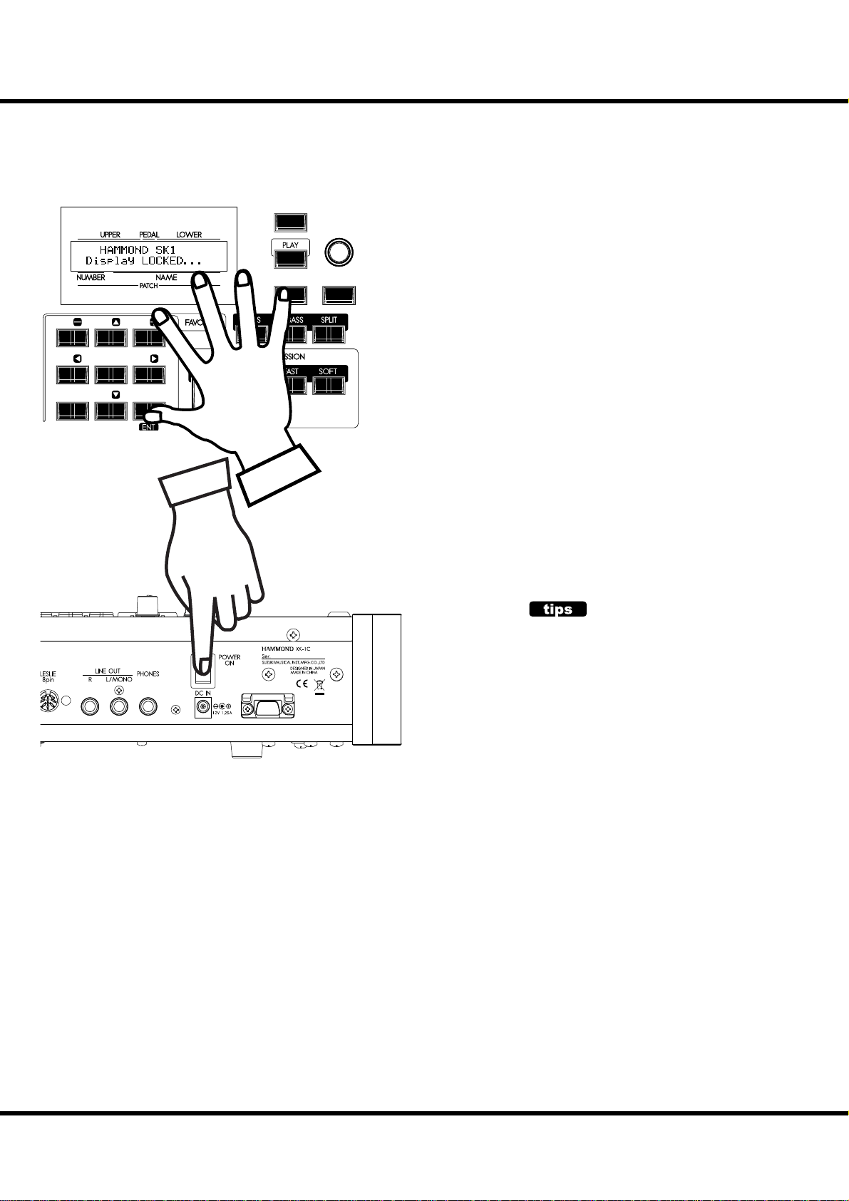
66
LOCKING THE DISPLAY
You can lock the display to avoid mistake while playing.
231
5
64
7 8 MANUAL
MENU /
EXIT
RECORD
VA L U E
ENTER
To lock the display, switch [POWER] on with pressing [RECORD] and [MANUAL] until “Display LOCKED” is displayed.
To unlock this, repeat the operation above until “Display
UNLOCKED” is displayed.
is function works listed below;
[MENU/EXIT] button (P. 60) is disabled.
[RECORD] button (P. 55) is disabled normally.
But you can record the patch by using “LOCKED 1-10”
(P. 25), or you can associate the favorite buttons by using
“ASSOCIATE” (P. 70) before locking the display.
“Short-Cut” function (P. 63) is disabled.
[DRAWBAR SELECT] buttons (P. 45) are still enabled.
NOTE: This feature will not released by Default-All or power on while
holding [RECORD] button.
USING REGISTERED PAGE
The [CONTROL] button can register a page in function mode. Even if the display is locked, you can
enter the registered page by using [CONTROL]
button (P. 63).
However, you cannot move the cursor if the page
has 2 or more parameters.
*#1 :-%
Owner’s Manual
Page 67

67
SETTING THE
PARAMETERS
Page 68

68
DRAWBAR
Drawbar sound parameters for each keyboard are set in this mode.
To locate this mode:
See the “Function mode” (P. 62) for operational details.
⓭⓮ ⓯⓰⓱ ⓲ ⓳⓴
❶❷❸❹ ❺❻ ❼❽❾ ❿⓫⓬
SETTING FOR MANUAL (LOWER & UPPER) DRAWBARS
❶ ORGAN TYPES
Select the manual keyboard organ type.
BType1: Traditional B-3/C-3 tone-wheel sound
BType2: Sound with more leakage noise and wow- utter
Mellow: With transparent sine waves
Vx: Transistor Organ, Vx type
Far t: Transistor Organ, Farf type
Pipe: Pipe Organ
When the organ type is set at Vx, Farf, or Pipe, the parameters (2) to (6) are unavailable.
❷ CLICK - ATTACK LEVEL
Sets the key-on click volume.
e higher the value, the louder the click gets. No key-click at 4. As the value goes
lower than 4, the attack rate becomes slower.
❸ CLICK - RELEASE LEVEL
Sets the key-off click volume.
e higher the value, the louder the click gets. No key-click at 4. As the value goes
lower than 4, the release rate becomes slower.
❹ CLICK - LOW PASS FILTER
Sets the key-click tone.
e setting range is 0 to 127. e higher the value, the brighter the sound.
❺ FOLDBACK - LOW
Sets the key-point from which the 16´ Drawbar folds back (= repeat the same octave
on the lower octaves of the keyboard).
e bottom key on the keyboard is displayed as “1C”. e setting range is 1C to 2C.
❻ FOLDBACK - HIGH
Sets the key from which the 1´ Drawbar folds back (= repeat the same octave on the
higher octaves).
e setting range is 4G to 5C.
NOTE: The Fold-back is possible not only with 1´ but also with 1⁄´, 1⁄´, 2´, 2⁄´ Drawbars.
❼ UPPER ZONE OCTAVE
Set the octave shift for the UPPER part. e setting range is -2 to +2.
❽ UPPER ZONE LOW
❾ UPPER ZONE HIGH
Set the sounding range of the UPPER part with these two parameters.
TONE-WHEEL SET
There are variations available for each virtual ToneWheel set of BType1, BType2 and Mellow. (P. 81)
KEY CLICK
On the traditional models such as B-3/C-3, a noise
occurred when keys were pressed and released,
due to the mechanical keying system employed on
the classic organs. That characteristic is replicated
here.
Loudness
Attack
Rate
Attack
Click
Release
Click
Release
Rate
Note On Note Off
EXAMPLES OF KEY-CLICK SETTINGS
Simulation of classic multi-contact keyboard B-3
and C-3: AT = 8, RL = 8
Simulation of a PCM synthesizer to produce the
key-click only at ‘attack’: AT = 8, RL = 4
Slow envelope like a pipe-organ: AT = 0, RL = 0
FOLD-BACK
As the number of the Tone-Wheels was limited on
the B-3/C-3, the very highest and lowest pitches
“folded back” on the keyboards, sounding the
same octave twice in a row. This function reproduces this characteristic.
Time
*#1 :-%
Owner’s Manual
Page 69

❿ LOWER ZONE - OCTAVE
Set the octave shift for the LOWER part. e setting range is -2 to +2.
⓫ LOWER ZONE - LOW
⓬ LOWER ZONE - HIGH
Set the sounding range of the LOWER part with these two parameters.
See page 102 for details of #7 to 12.
69
SETTING THE PEDAL PART
⓭ ORGAN TYPE
Set the Organ type for the Pedal part.
Normal: The traditional tone wheel sound of the B-3/C-3.
Muted: Analog oscillating sound as heard on the Classic X-5.
Synth1: Saw-tooth waveform with the lter-sweep.
Synth2: Dull square wave.
When the “Pipe” Organ type is selected by (1), only Pipe Organ pedal sounds are heard,
regardless of this parameter. Also, parameters (14) to (17) are unavailable.
⓮ ATTACK
is allows you to set the Pedal Attack Rate and the Key-Click Volume at ‘attack’ and
‘release’.
MAX CLK: Immediate attack and the key-click is loud.
NORM CLK: Immediate attack and the key-click is normal.
SOFT CLK: Immediate attack and the key-click is soft.
NO CLK: A slightly slower attack without key-click.
SLOW ATK: Slow attack without key-click.
⓯ DECAY RATE
is allows you to determine whether the Pedal voice remains at the same volume as a
note is held, or if the voice decays, as like a plucked string.
e setting range is 1 - 5 and C. e higher the value, the longer the decay time. ere
is no decay at C.
⓰ SUSTAIN LENGTH
is allows you to set the Release Rate (= the decay time after key release), when the [P.
SUS] button is ON.
1 is the shortest, and 5 is the longest decay time.
NOTE: You can locate this page by holding down the [P. SUS] button as well.
⓱ VELOCITY
is allows you to set the response to playing velocity. e setting range is OF and 1
- 4. At OFF, the volume does not change however hard you play the key. As the value
increases from 1 - 4, the sounds gets louder even if the key is played softly.
⓲ KEY MODE
is allows you to set the Pedal polyphony.
POLY: Makes it possible to play chords(up to 3 notes).
MONO: Only the lowest note will sound, when you play a chord.
⓳ PEDAL ZONE - OCTAVE
Set the octave shift for the Pedal part. e setting range is -2 to +2.
⓴ PEDAL ZONE - LOW
PEDAL ZONE - HIGH
Set the sounding range for the PEDAL part with these two parameters.
See page 102 for details of #19 to 21.
Loudness
Note On Note Off
Attack
Decay = "C"
Decay =
"1" - "5"
Sustain =
"On"
SUSTAIN
Unlike synthesizer nomenclature, on the this
keyboard “Sustain” refers to note decay after
note release. On a synth envelope generator
this setting would be called “T4” or “Release”.
ZONE
The “ZONE” set in these modes is the setting of
the sounding range for each part of the organ
section.
See page 102 for details.
Time
NOTE: All the parameters in these modes
are Patch Parameters. They are recorded into the Patch.
Setting the Parameters
Page 70

70
❶
P A T C H
In this mode you a name your patch, set which parameters load, and how to link to
the Favorite buttons.
To locate this mode:
See the “Function mode” (P. 62) for operational details.
~ omitted ~
⓫
❸❹ ❺ ❻ ❼ ❽❾❿
❷
⓳⓬
PATCH NAME
❶ Patch NAME (P)
Name the present patch using up to 15 letters.
Move the cursor by the [W][X] buttons. en select letters
with the [VALUE] knob.
PATCH LEVEL
❷ PATCH LEVEL (P)
Adjusts the present patch volume. It is controlled by MIDI
control change #7 “Volume” also.
e setting range is 0 to 127.
NOTE: These parameters 1 and 2 (P) are Patch Parameter. They are re-
corded in each patch. They are lost unless you save the patch.
PATCH LOAD
ese are for setting which parameters are loaded when a patch
is called. Sets whether or not to load:
❸ PATCH LOAD - UPPER Registration (G)
Drawbar registration of the UPPER part.
❹ PATCH LOAD - LOWER/PEDAL Registration (G)
Drawbar registration of the LOWER and PEDAL parts.
❺ PATCH LOAD - DRAWBAR (G)
e parameters such as organ type or percussion.
❻ PATCH LOAD - INTERNAL ZONE (G)
e parameters relating with Internal Zone or Coupler (Manual Bass).
❼ PATCH LOAD - EXTERNAL ZONE (G)
e parameters specifi c to the External Zone to control external MIDI equipment.
❽ PATCH LOAD - DRAWBAR EFFECT (G)
e parameters specifi c to the Patch Level and Eff ects (Overdrive, Multi-Eff ects, Equalizer).
❾ PATCH LOAD - ANIMATION (G)
e parameters specifi c to the Leslie, Vibrato & Chorus eff ects.
❿ PATCH LOAD - REVERB (G)
e Reverb parameters.
NOTE: Each Patch Load parameter is a Global Parameter. It is record-
ed when the value is set. Common for each patch.
FAVORITES
⓫ FAVORITE ACCESS (G)
is is for setting the action of the Favorite Buttons.
ASSOCIATE:
Each number button calls the related patch.
If you touch a number button holding down the [RECORD] but-
ton, it relates the number button to the currently selected patch.
OVERWRITE:
In addition to above, if you touch each number button holding
down the [RECORD] button, it records the current setting to the
selected patch.
LOCKED 1-8:
Each number button calls the corresponding patch, U1-1 ... U1-8.
If you touch a number button holding down the [RECORD] but-
ton, it records the current setting to the corresponding patch,
U1-1 ... U1-8.
DIRECT:
This is for directly calling the patch, using the number buttons.
To call a patch, enter the 3 digit patch number and then touch
the [ENTER] button.
<Example>
to select lowest digit (U1-2 to U1-3) ... [3], [ENTER]
to select lower 2 digits (U1-2 to U2-3) ... [2], [3], [ENTER]
to specify all (U1-2 to P2-3) ... [2], [2], [3], [ENTER]
You can not associate the patch to each number button.
⓬to⓳ FAVORITE PATCHES (G)
Displays and changes the Patches related to each Number button.
You can enter the these page by pressing and hold the [1] - [8]
button also.
NOTE: “G” means “Global”. These parameters will be recorded when
set, and are common in each patch.
*#1 :-%
Owner’s Manual
Page 71

TUNE
In this mode, the entire keyboard is tuned.
To locate this mode:
See “Function mode” (P. 62) for operation details.
❶ ❷
TRANSPOSE
❶ TRANSPOSE
You can set Transpose in the range from -6 to +6 semi-tones.
Transpose is mapped to the following points:
i) Between the built-in keyboard and the on-board sound engines.
ii) Between the MIDI IN and the on-board sound engines.
iii) To the External Zone.
iv) When the MIDI pedalboard XPK-100 is connected, transpose value will syn-
chronize with it.
NOTE: Transpose is a temporary parameter, and is not recorded to any patch. When the
power is switched OFF, it returns to 0.
71
MASTER TUNE
❷ MASTER TUNE
is is for tuning the entire keyboard.
e setting range is A = 430 to 450 Hz.
NOTE: Master Tune is a global parameter. It is recorded when it is set, and is common for
each patch.
Setting the Parameters
Page 72

72
CONTROL
is mode is for setting the controller.
Please insure that the Expression Pedal and Foot Pedal are properly con-
nected before adjusting their settings.
To locate this mode:
or, touch the [CONTROL] button.
See “Function mode” (P. 62) for operation details.
⓴
⓱⓲ ⓳
⓮⓯⓰
⓬⓭
⓫
❹❺ ❻❼❽ ❾❿
❶ ❷❸
FOOT SWITCH
❶ FOOT SWITCH - DEVICE (G)
is is for selecting the equipment connected to the FOOT SWITCH jack.
FOOT SW: Foot Switch connected.
CU-1: Optional Leslie Mode Switch (CU-1) connected.
❷ FOOT SWITCH - TIP MODE (G)
is sets the Foot Switch function.
OFF: Does not function.
LESLIE S/F ALT, MOM, TRI:
Switches the Leslie E ect Slow/Fast/Stop.
At ALT, Fast / not (Slow or Stop - it set by [STOP] button) is toggled every time the foot
switch is pressed.
At TRI, it is switched to Stop when the foot switch is further held down for longer than a
second.
At MOM, it is switched to Fast only while the foot switch is held down. When released, it is
switches to not (Slow or Stop - it set by [STOP] button).
GLIDE:
The pitch bends while the foot switch is pressed down the interval is determined by a
parameter setting.
PATCH FWD, REV:
Advance the Patch Forward or Reverse it.
FAVORITE FWD, REV:
Advance the Favorite Forward or Reverse it.
SPRING:
This generates the sound of the spring reverb being shaken.
DELAY TIME:
Sets the delay time (P. 86, 95) of the E ects, at the interval of pressing the foot switch. The
delay sound goes out, while the foot switch is held down.
DAMPER:
Holds played notes while the foot switch is depressed as does the damper pedal on a
piano.
TIP AND RING
The typical stereo plug, there are 3 metal parts.
The end is called the “Tip”, the middle portion is
the “Ring”. The part on the cord side is called the
“Sleeve”.
This keyboard requires a foot switch that uses a
Stereo Jack. Two Mono-Jack foot switches may
be used, and can have discrete functions, if a Left/
Right stereo splitter is used.
Tip
Ring
Sleeve
SPRING REVERB
The Hammond Organ company actually invented
the spring reverb for its organs in the 1940’s. The
e ect was obtained with a length of spring and a
few pickups. If the spring was disturbed, it would
make a large crashing noise that was usually considered a nuisance, but sometimes was used as a
program sound e ect. The Reverb here is digital,
but the “crash” e ect is re-created here.
*#1 :-%
Owner’s Manual
Page 73

MANUAL BASS:
Triggers the Manual Bass note of Pedal part.
BASS 1C - BASS 3C
Triggers the speci ed note of Pedal part.
❸ FOOT SWITCH - RING MODE (G)
is sets the Ring side function, when the foot switch connected to the foot switch jack
is of the TRS (Tip, Ring, Sleeve) specifi cations.
73
3RD PARTY EXPRESSION PEDAL
When using a Korg XVP-10 type of pedal, connect the EXPRESSION jack of the XVP-10 to the
EXP. PEDAL jack of the this keyboard with a TRS
(Tip, Ring, Sleeve) cable.
EXPRESSION
❹ EXPRESSION - SOURCE (G)
Sets the source of expression control.
PED (NORM):
For the (Optional) Hammond-Suzuki EXP-50 or EXP-20 pedal etc.
PED (REV):
For using a Korg XVP-10 type of Expression Pedal etc.
MIDI: For using expression information received at the UPPER keyboard channel.
❺ EXPRESSION - MONITOR
Displays the current value of expression. In case of no sound or no change when the
expression pedal is pressed, this monitor shows whether the expression value changes or
not, so you may discover the cause of trouble (if any). is can also be an indicator when
playing from low volume to fade in.
❻ EXPRESSION - MINIMUM LEVEL (G)
Sets the volume at minimum expression.
e setting range is OFF, -40dB to 0dB. At OFF the instrument is silent when Pedal is
at Minimum (all the way back). e other value points represent the lowest volume that
will be present at the Pedal’s minimum position.
❼ EXPRESSION - LIMIT LOW FREQUENCY (G)
❽ EXPRESSION - LIMIT HIGH FREQUENCY (G)
Sets the amount of Low or High Frequency to remain, when the expression is set at
minimum.
e setting range is OFF, -40dB to 0dB. At OFF the sound totally disappears, but at
other value points the set volume is kept, even if the expression is at minimum.
❾ EXPRESSION - GAIN (S)
Sets the gain (range) of the connected expression pedal.
Depending on the type of the connected expression pedals, the expression value may not
change. In such case, adjust this parameter to obtain the desired response.
❿ EXPRESSION - CURVE (S)
Adjusts change of expression value corresponding to the angle of the depressed expression pedal.
e setting range is 1 to 3. Refer each curve to the bottom right illustration or try playing
live to discern which curve is correct for you.
NOTE: The parameters indicated (S) are system parameters. They are recorded when set, and are
common in each Patch.
GLIDE
⓫ GLIDE - RANGE (P)
Sets the bend range of pitch by semi-tone. Setting range is -24 to +12.
⓬ GLIDE - TIME (P)
Sets the time from the start of glide to reach the pitch set at (11). e setting range is
0.1 to 5.0 seconds.
⓭ GLIDE - AMP (P)
Engages a “fade” along with the Glide, where the volume drops in tandem with the pitch
to total silence.
EXPRESSION LIMIT
One of the human ear’s characteristics is that
when the volume falls, the sound of the high
or low frequencies becomes di cult to hear.
Using expression limit, you can hear the revised frequency response.
Vintage B-3 preamps age in di erent ways-one
symptom is the organ’s timbre may change
with Expression pedal travel. This is a desirable
characteristic for some.
Loudness
Expression = Maximum
LF
Limit
120Hz 4kHz
Loudness
Expression = Minimum
LF
Limit
120Hz 4kHz
Value
127
Output
Min. Level
Output
Min. Level
HF
Limit
Frequency
HF
Limit
Frequency
3
2
1
0
NOTE: The parameter with (P) indicated is
a patch parameter, and is recorded
to each patch. (G) indicates “global
parameter”, which is recorded upon
being set, and is common with each
patch.
Degree
Setting the Parameters
Page 74

CONTROL - continued
74
⓴
⓱⓲ ⓳
⓮⓯⓰
⓫
⓬⓭
❹❺ ❻❼❽ ❾❿
❶ ❷❸
DAMPER
⓮ DAMPER - UPPER (G)
⓯ DAMPER - LOWER (G)
⓰ DAMPER - PEDAL (G)
Assigns the DAMPER to the various divisions of the this keyboard.
DISPLAY
⓱ DISPLAY - SHORT CUT (G)
Sets the short cut waiting time.
e setting range is 0 to 2 seconds. At NO the short cut feature is disabled.
⓲ DISPLAY - TIME OUT (G)
Sets the time for returning to the previous mode from the mode displayed by the
short cut operation.
e setting range is 4 to 16 seconds. At NO the screen will not return to the previous mode.
⓳ DISPLAY - POP UP (G)
Sets the interval at which the Pop Up is displayed when you move the [OVERDRIVE] knob.
e setting range is 0.5 to 2 seconds. At NO no Pop Up is displayed.
DAMPER
Or “Sustain” pedal-analogous to the RIGHT pedal
on a piano. Sounds are held when this pedal is
depressed. Called “Damper” due to the fact that
when the pedal was depressed on a piano, the
mechanism that muted or “damped” the strings
was raised, allowing the piano strings to ring free.
KEYBOARD
⓴ SOUNDING POINT (S)
Set the sounding point of the built-in keyboard is played.
DEEP All the section sounds on the deep point in the stroke.
AUTO The organ sound at the shallow point when striking the keys lightly, it makes a very lively
direct way of playing possible, But when the parameter “Percussion - Velocity” (P. 76 #6) is
used the sounding point is always deep.
Owner’s Manual
*#1 :-%
NOTE: The parameter with (P) indicated is a
patch parameter, and is recorded to
each patch. (G) indicates “global parameter”, (S) indicates “system parameter”,
which is recorded upon being set, and
is common with each patch.
Page 75

75
Setting the Parameters
Page 76

76
PERCUSS ( Percussion)
is mode is for setting the parameters of the percussion sounds.
To locate this mode:
or, keep pressing either of the [ON], [THIRD], [FAST], [SOFT] buttons for a
moment.
See “Function mode” (P. 62) for operation details.
❽❾
❺❻❼
❸❹
❶ ❷
❶ LEVEL SOFT
❷ LEVEL - NORMAL
Controls the percussion volume levels. e Normal level is
set by the NORM setting, and SOFT is the level when the
[SOFT] button is ON.
❸ DECAY - SLOW
❹ DECAY - FAST
Controls the percussion decay time. e Slow rate is set by
SLOW setting, and FAST is the time when the [FAST] button
is ON.
e setting range is 1 to 9 and C. As the value is raised, the
decay time grows longer. At C (continuous) there is no decay,
and the percussion sound is sustained while keys are pressed.
❺ KEYBOARD - TOUCH
Sets the touch response of the percussion.
ON: Legato playing will result in the First note hit engaging the per-
cussion, and none after.
OFF: The envelopes reset with each key hit and percussion sounds on
every note.
❻ KEYBOARD - VELOCITY
Links the percussion volume to velocity.
ON: A harder strike produces a louder percussion sound.
OFF: Regardless how hard you play, the volume remains the same.
❼ KEYBOARD - KEY TRACK
Attenuates the percussion volume by keyboard position.
ON: The higher the note is, the lesser the volume.
OFF: No change in volume.
❽ DRAWBAR - 1´ CANCEL
Mutes the UPPER 1´ Drawbar while using the percussion.
ON: Mute active
OFF: No mute.
❾ DRAWBAR - LEVEL
Reduces the UPPER Drawbar volume while using the percussion (except [SOFT] button is ON).
-5dB: Reduces the volume in similar response to the classic B-3/C-3.
-3dB: Slight reduction in volume.
0dB: Does not reduce the volume.
NOTE: All the parameters of these modes are patch parameters, and
are recorded to the respective patches.
TOUCH
The percussion generator on the vintage B3/C-3 had a single envelope, which would not
recycle until all keys were raised. Originally
thought to be a defect, the resulting response
became a desired trait.
1´ CANCEL
The B-3/C-3 had no exclusive key contact for
the percussion, but, used the 1´ contact. This
is simulated on this keyboard.
DRAWBAR LEVEL
When the percussion was activated on the
B-3/C-3, the volume of the Drawbars became
slightly softer in volume. This is simulated on
this keyboard.
*#1 :-%
Owner’s Manual
Page 77
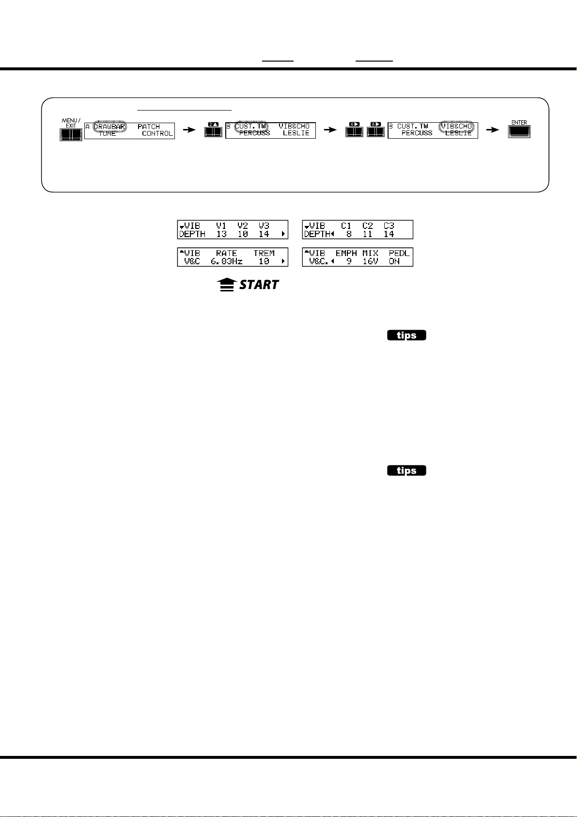
VIB&CHO ( Vibrato & Chorus)
In this mode, the settings specifi c to Vibrato and Chorus are adjusted.
To locate this mode:
or, keep pressing either of the [V1/C1], [V1/C2], [CHORUS], [ON UPPER],
[ON LOWER] buttons for a few seconds.
See “Function mode” (P. 62) for operation details.
❻❼❽ ❾❿⓫
❶ ❷❸❹❺
77
❶ RATE
Sets the Speed of the Vibrato and Chorus eff ect.
e setting range is 6.10 - 7.25 Hz.
❷ VIBRATO - TREMOLO
Sets Tremolo (amplitude modulation) of the Vibrato and Chorus eff ect.
e setting range is 0 - 15.
❸ EMPHASIS
Sets Emphasis (high frequency boost) of the Chorus eff ect (C1 / C2 / C3).
e setting range is 0 - 9 dB.
❹ MIX
Sets Mix balance of the Chorus eff ect (C1 / C2 / C3).
e setting range is D64 (only the Direct tone, no vibrato tone) - EVEN - 63V (only the
Vibrato tone, no direct tone).
❺ PEDAL
Sets Vibrato and Chorus on the Pedal part by [LOWER] button.
e setting range is ON/OFF.
❻ DEPTH V1
❼ DEPTH V2
❽ DEPTH V3
❾ DEPTH C1
❿ DEPTH C2
⓫ DEPTH C3
Sets the Depth of each Vibrato and Chorus eff ect mode.
e setting range is 0 - 15.
NOTE: The parameters in these modes are Preset Parameters and are recorded to each Preset.
CHORUS EFFECT
The Hammond Chorus/Vibrato is not an everyday DSP e ect. It is a re-creation of the vintage mechanical scanner that was included
on-board the classic B-3, through executed in
the digital realm.
PEDAL
On the vintage B-3/C-3, the Vibrato and Chorus a ects not only Lower part but also the
Pedal part via [LOWER] (on the B-3, “GREAT”)
tablet by the circuit structure. It is divided on
later models.
This parameter simulates that.
NOTE: All the parameters in these modes
are Patch Parameters. They are recorded into the Patch.
Setting the Parameters
Page 78

78
LESLIE
In this mode, the settings are made for the on-board Leslie Eff ect
and the External Leslie Speaker.
ere are many parameters related to the Leslie eff ect, but they
cannot set each parameter every Patch by Patch.
To locate this mode:
or, keep pressing either of the [BYPASS], [STOP], [FAST] buttons for a few seconds.
See “Function mode” (P. 62) for operation details.
⓳⓴
⓭⓮⓯ ⓰ ⓱ ⓲
❻❼❽ ❾❿ ⓫ ⓬
❸❹ ❺
e on-board Leslie parameters are grouped in macro-settings
called “CABINETS”. You select the CABINET NUMBER in the
Patches where this selection is saved as part of the Patch.
❷
❶
CABINET NUMBER
❶ CABINET NUMBER (P)
Selects the Cabinet Number to use in the Patch.
e setting range is P1 to P8 (not-overwritable) and U1 to U8 (overwritable). If any
of the Leslie parameter are edited, “*” is displayed on the left side.
LESLIE PARAMETERS
❷ CABINET NAME (L)
Sets the Cabinet Name by up to 10 characters.
Move the cursor with the [W][X] button and select letters with the [VALUE] knob.
Allowable values are: symbols, digits and the large and small Alphabet.
e name and following (L) parameters are not recorded until the Cabinet Macro is
recorded into memory (See the next paragraph.)
❸ AMP (L)
is is for setting the type of the virtual Amplifi er.
Solid: Flat characteristic Amp
Tub e: Tube-style amp with Mild characteristics.
❹ SPEAKER (L)
is is for setting the virtual Speaker.
RotSmall: A small Leslie speaker, such as the Leslie 145
RotLarge: A large Leslie speaker, such as the Leslie 122
Station: A xed speaker, such as the Hammond PR-40
CONCEPT OF THE CABINET NUMBER
One Cabinet is equivalent to a virtual Leslie speaker made with the Leslie parameter.
This is a Patch parameter.
#1
#2
#3
*#1 :-%
Owner’s Manual
Page 79
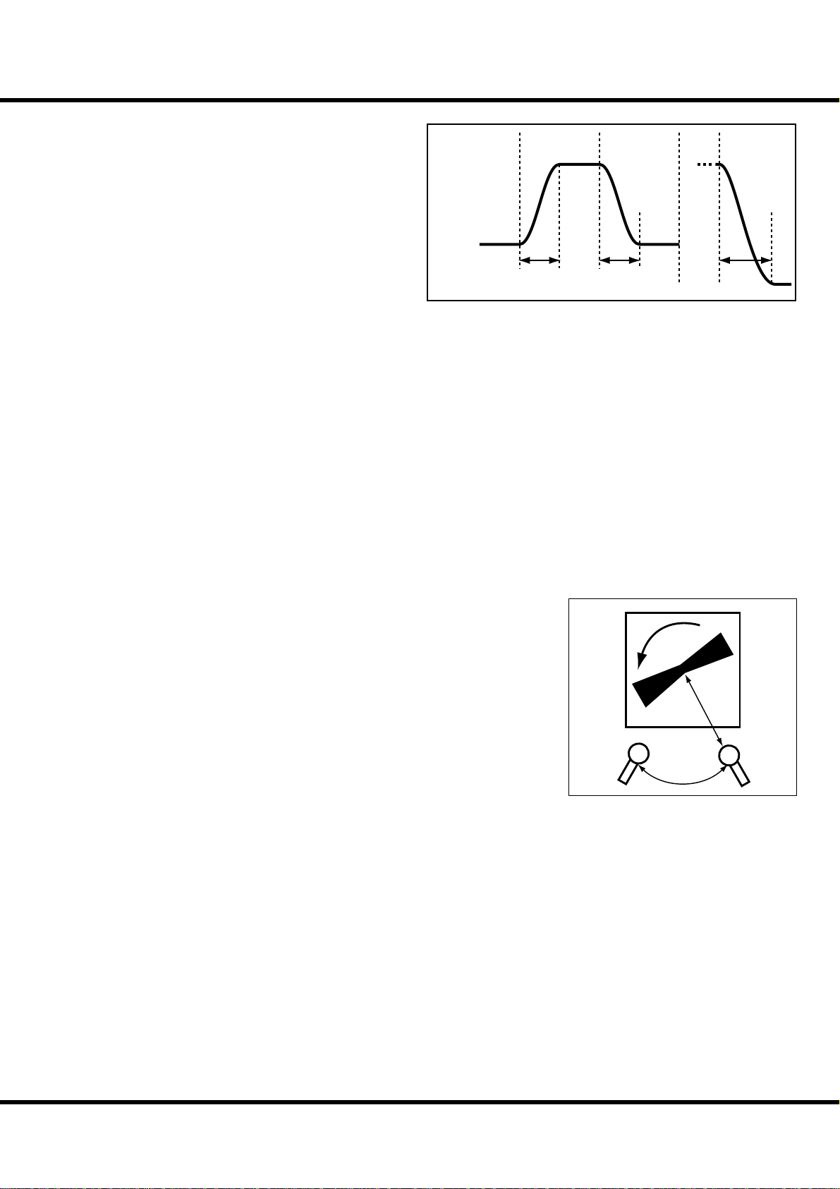
79
❺ COLORATION(L)
Switches On/Off the coloration of the speaker enclosure.
❻ SLOW SPEED - HORN (L)
⓭ SLOW SPEED - BASS (L)
Mode:
SLOW FAST SLOW FAST STOP
Sets the speed of the rotor at slow mode.
e setting range is 0, 24 to 318 rpm. At 0, no rotation.
❼ FAST SPEED - HORN (L)
⓮ FAST SPEED - BASS (L)
Rotor
Speed:
Sets the speed of the rotor at the fast mode.
e setting range is 0, 375 to 453 rpm. At 0, no rotation.
❽ HORN LEVEL (L)
⓯ BASS LEVEL (L)
Sets the volume of each rotor. e setting range is 0 to -12dB.
❾ RISE TIME - HORN (L)
⓰ RISE TIME - BASS (L)
Sets the time for the rotors to “ramp up” to the ‘Fast Speed’, when switching from ‘Slow’
or ‘Stop’ to the ‘Fast’ mode.
e setting range for the Horn Rotor is 0.2 to 5.0sec., and the Bass Rotor is 0.5 to
12.5sec.
❿ FALL TIME - HORN (L)
⓱ FALL TIME - BASS (L)
Sets the time for the rotor to reach the ‘Slow Speed’, when switching from ‘Fast’ to ‘Slow’
mode.
e setting range for the Horn Rotor is 0.2 to 5.0sec., and that for the Bass Rotor is 0.5
to 12.5sec.
⓫ BRAKE TIME - HORN (L)
⓲ BRAKE TIME - BASS (L)
Sets the time for the rotor to stop, when switching from ‘Fast’ to the ‘Stop’ mode.
e setting range for the Horn Rotor is 0.2 to 5.0sec., and the Bass Rotor is 0.5 to
12.5sec.
⓬ HORN CHARACTER (L)
Sets the tone of the Horn Rotor.
“FLAT” has no boost or cut in frequencies, and the “MID” or “DEEP” have “peaks” in
various tonal ranges, to mimic the particular characteristics of the horns.
⓳ MIC - ANGLE (L)
Sets the virtual locations of the two virtual microphones for the virtual Leslie Speaker.
e ANGLE decides the distance between the two virtual mikes. e setting range is 0
to 180°. Farther settings exhibit more stereophonic characteristics.
⓴ MIC - DISTANCE (L)
Sets the distance between the virtual Leslie Speaker and the virtual microphones.
e setting range is 0.3 to 2.7m. Setting the range “further away” will result in a less
intense sound.
NOTE: When you operate the parameters 2 to 20, the setting range will be lost upon selecting
another Cabinet, another Patch or powering OFF the unit, unless you record the changes
into the User “Cabinet” (procedure following).
Rise
Time
Fall
Time
Brake
Time
Distance
Angle
Setting the Parameters
Page 80

LESLIE - continued
80
EXTERNAL LESLIE SPEAKER
LESLIE CHANNELS
Sets the channel for the Leslie speaker connected to the LESLIE 8-PIN jack.
1ch: For connecting a 1 channel Leslie cabinet such as the 122XB, 3300/3300W (with no sta-
tionary speakers). The Drawbar and the percussion sounds are output only from the rotary
channel always. The Pipe voices are from the LINE OUT jack.
3ch: This is for connecting a 3 channel Leslie cabinet such as the 2101/mk2. The Drawbar and
the percussion sounds are output from the rotary channel, the Pipe voices and bypassed
Drawbar and percussion sounds are from the stationary channel of the Main and Aux.
NOTE: This is a system parameter. It is recorded upon setting, and is common with all patch-
es.
RECORD THE CABINET
Record the Leslie Parameter (#2 to #20 on the previous page) to
the Cabinet Numbers and use them selecting at the patches.
1
Give a name to the cabinet as desired.
2
7 8 MANUAL
3
MENU /
EXIT
VA L U E
RECORD
Select the Cabinet Number to record with the [VALUE] knob.
MENU /
EXIT
VA L U E
RECORD
231
5
64
ENTER
4
MENU /
EXIT
RECORD
ENTER
VA L U E
ENTER
Press the [RECORD] button in the Leslie Parameter setting
mode (#2 to #20).
e Cabinet Select mode is displayed.
Owner’s Manual
*#1 :-%
Recording is made upon pressing the [ENTER].
e display is as the above during the treatment.
NOTE: If you don’t wish to record, touch the [MENU/EXIT] button.
Page 81

CUST. TW ( Custom Tone-Wheels)
In this mode, you select or edit the characteristics of each tone wheel set
to be used on the manual keyboards.
To locate this mode:
See “Function mode” (P. 62) for operation details.
❹❺❻❼ ❽
❸
❷
❶
81
❶ TONEWHEEL SET
Selects the virtual Tonewheel sets to edit: “BType1”, “BType2”
and “Mellow”.
Also, the temporary (= the present setting) automatically
switches to the selected virtual Tonewheel set just selected now.
❷ CUSTOM NUMBER (P)
is is for selecting the “CUSTOM NUMBER” to use or compile. e symbol “*” will be displayed when the virtual Tonewheel Parameters are edited.
NOTE: This parameter is a Patch Parameter. It is recorded into the
Patch.
❸ CUSTOM NAME
You can name the CUSTOM virtual TONEWHEELS set using up to 10 letters.
Move the cursor by the [W] [X] button and choose the letters
by the [VALUE] knob or [-] [+] button.
e name set here, as well as the Tonewheel Parameters below,
will be discarded, if not recorded (procedure following).
❹ WHEEL NUMBER
Select the Number of the Wheel you want to regulate.
To select the Wheel Number, select the [VALUE] knob here,
or slightly move the footage of the Drawbar while depressing
the key you want to regulate (see the illustration on the right).
When the Wheel Number is selected, each parameter for the
wheel (#5, #6, #7, #8) is displayed.
NOTE: Set the [TRANSPOSE] and [OCTAVE] at “0” to select a correct
wheel.
INITIAL VALUE OF THE CUSTOM NUMBER
The typical settings are saved to the Number 1 - 4,
as the initial value.
For example, to the BType1, “Real B-3” simulating
the well-preserved B-3/C-3 and “80’s Clean” with
less noise, rough sound “Noisy”, and “Noisy 60” with
louder leakage noise is stored.
MENU /
EXIT
VAL UE
ENTER
RECORD
13
5
7 MANUAL
How to select the WHEEL NUMBER
Setting the Parameters
Page 82

CUST. TW (Custom Tone-Wheels) - continued
82
❹❺❻❼ ❽
❸
❷
❶
❺ LEVEL
is is for setting the volume of a virtual wheel.
e setting range is -20 to +2dB. If you increase the value, it gets louder.
❻ CUT OFF FREQUENCY - LPF
is is for setting the FREQUENCY to cut the TREBLE of a virtual wheel.
If you increase the value, a leakage noise is heard besides the original Tonewheel
pitch.
If you decrease the value, the sound gets sweet and mild, as the treble is cut off .
e setting range is 0 - 127.
NOTE: If you decrease the value too low below the fundamental Tonewheel pitch, the wheel
volume will be reduced.
❼ RESONANCE - LPF
is adjusts the boost or reduction of the level surrounding the Cut Off Frequency LPF (#6). [sometimes called “Q” in synth technology]
e setting range is 0 - 127. e higher value boosts treble, and lower values cut
treble smoothly.
❽ CUT OFF FREQUENCY - HPF
is is for setting the FREQUENCY to cut the BASS of this wheel.
If you decrease the value, a motor hum (= noise) is heard besides the original virtual
Tonewheel sound.
e setting range is 0 - 127.
NOTE: If you increase the value too high above the original tonewheel pitch, the sound will
get “Thin”.
Soft
Loud
Coil
Tone-wheel
Magnet
Concept of the LEVEL ADJUSTMENT
Loudness
Cut Off Frequency
Resonance
HPF LPF
Frequency
LEAKAGE NOISE
In the vintage electro-mechanical Hammonds,
sometimes the signal from adjacent tonewheels
would be picked up (or “leaked”) along with the
current tonewheel in play. This “hash” noise, another Hammond anomaly originally considered to
be a defect grew to be an integral part of the Hammond sound.
“Mellow” does not include the Leakage Noise.
NOTE: Editing and Recording any Custom Tonewheel pro le (#3 to #8) will a ect any Patch
using that Pro le. After editing, you must record your changes to save them (Procedure following).
Owner’s Manual
*#1 :-%
DISTORTION
If you raise the Level and Resonance values too
much, it changes the gain in the sound engine and
may sometimes cause distortion, or unpleasant
noise.
Page 83

Record the CUSTOM virtual TONEWHEELS setting
e Tonewheel Parameters (= 3 - 8 of the previous paragraph) are for determining the Custom Number for recording. e Custom Number is selected and used, when you play.
1
Enter the Custom Name if desired.
83
2
7 8 MANUAL
3
MENU /
EXIT
VA L U E
Touch the [RECORD] button in the setting mode of the Tonewheel Parameters.
RECORD
ENTER
e mode for selecting the Custom Number to be recorded will
be displayed.
231
5
64
MENU /
EXIT
RECORD
VA L U E
ENTER
Select the Custom Number to be recorded by the [VALUE] knob.
4
MENU /
EXIT
RECORD
VA L U E
ENTER
It will be recorded if you touch [ENTER] button.
e display will be as illustrated, while the recording is treated.
NOTE: To dismiss the record sequence, touch the [MENU/EXIT] button.
Setting the Parameters
Page 84

84
PIPE
In this mode, you edit the characteristics of each pipe.
To locate this mode:
See “Function mode” (P. 62) for operation details.
... omitted ...
❶ ❷❸ ❹ ❺ ❻ ❼
❶ PIPE NUMBER
Select the PIPE which you desire to edit by [S],[T] buttons.
ere are 20 pipes which according to Drawbars from “Bourdon 16´” to “Principal
Chorus 4´ + Mixture IV” (P. 44).
❷ VOLUME (Pi)
Adjusts the volume of the pipe. e setting range is 0 to 127.
❸ DETUNE (Pi)
Detunes the pitch of pipe from accurate pitch by cent (⁄ of semitones).
e setting range is -50 - 0 - +50.
❹ CHIFF (Pi)
Sets the “Chiff ” noise of beginning of notes.
OFF: No sounds the chi noise.
SOFT: Sounds the chi noise slightly.
MID: Sounds the chi noise medium.
LOUD: Sounds the chi noise maximum.
NOTE: Some pipes does not a ect the chi parameter i.e. “Hautbois 8´”.
❺ CUT OFF FREQUENCY (Pi)
Adjusts the tone quality of the pipe.
e setting range is -64 to 0. At 0, all of pipe sounds are heard. e sound becomes
mellower by the decreases value.
❻ PAN - DIRECTION (Pi)
Adjusts the basic direction of the pipe.
e setting range is L64 - C - R63 (Left - Center - Right).
DETUNE
The beating is heard by sounding detuned pitch
on sounding accurate pitch.
Each pipe can be detuned for comfortable beating.
But it may out of tune by too much detune.
Generally, they are e ective that set at “-” side for
lower octave pipes, set at “+” side for upper octave
pipes.
CHIFF
The slight pu of air that is heard from certain
pipes upon playing.
*#1 :-%
Owner’s Manual
Page 85

❼ PAN - IMAGING (Pi)
Sets the arrangement of the pipe.
FIX: Sounds the FIXed direction which set by #6 for all notes.
L-R: Sounds Left to Right which according to the keys.
C
C
D
E
E
F
F
G
G
A
B
B
R-L: Sounds Right to Left which according to the keys.
C
C
D
E
E
F
F
G
G
A
B
B
85
MISSING OR UNEVEN VOICE?
The pipe stops are spread in a stereo array. If
this keyboard connected in MONO, and the
this keyboard system is set to “Stereo”, some
notes and voices may be missing, or sound uneven. In that case, set the “Audio mode - Output” (P. 97 #1) at “MONO”.
This will disable the Pipe Stereo Imaging.
PYR: Like the PYRamid, sounds center to sides which according to the keys.
C
C
E
F
G
A
B
INV: Like the INVerted pyramid, sounds sides to center which according to the keys.
C
D
E
F
D
E
F
G
B
C
E
F
G
G
A
B
B
NOTE: The parameters of these modes (Pi)
are Pipe parameters. They are recorded when they are set, and are
common for each patch.
Setting the Parameters
Page 86

86
❺❻
OD / EFF ( Overdrive / E ects)
In this mode, Overdrive and the Multi-Eff ects are adjusted.
To locate this mode:
Or, turn the [OVERDRIVE AMOUNT] knob with pressing [MENU/EXIT] button.
See “Function mode” (P. 62) for operation details.
❶ ❷❸
❹
OVERDRIVE
❶ OVERDRIVE - SWITCH
Turns the Overdrive “On / Off ”.
❷ OVERDRIVE - DRIVE
Adjusts the drive component of the Overdrive. e higher you raise the value, more
distortion is obtained. It is linked with the [OVERDRIVE AMOUNT] knob on the
top panel.
❸ OVERDRIVE - EXPRESSION
Sets the response of Overdrive to Expression Pedal Value.
EX-OD:
Overdrive e ect increases/decreases along with volume.
OD-EX:
Overdrive e ect remains constant, only volume increases/decreases.
OD ONLY:
Volume remains constant, Expression pedal increases/decreases overdrive e ect.
INPUT:
Expression pedal attenuates INPUT level to Overdrive e ect. Lesser Volume control.
❹ OVERDRIVE - TYPE
Sets the characteristic of the Overdrive.
Tub e: Replicates a tube-driven amp.
Solid: Replicates a solid-state stomp box.
Clip: Accurate hard clip.
EPAmp: Replicates the pre-ampli er of an electric piano.
Level
Time
MULTI-EFFECTS
❺ EFFECT - SWITCH
Turns the Multi-Eff ects “On / Off ”.
❻ EFFECT TYPE
Selects the Multi-Eff ect type. e following eff ects are available.
Tremolo, Auto Pan, Wah-Wah, Ring Mod., Phaser, Flanger, Chorus, Delay
e parameters for the Multi-Eff ects are vary by type (following).
Owner’s Manual
*#1 :-%
Page 87

Tremolo
Tremolo modulates the volume at a set cycle.
87
Level
❻❼❽❾
❼ TREMOLO - WAVEFORM
Sets which waveform is used to modulate the volume.
Tri: Triangle wave. The volume changes smoothly.
Sqr: Square wave. The volume suddenly rises and falls.
Saw: Sawtooth wave. Repeated decaying sound is obtained.
S&H: Sample & hold. The volume changes randomly.
DSqr: Dull square wave like the old electric piano e ect.
❽ TREMOLO - RATE
Adjusts the speed of the tremolo cycle.
e setting range is 0 to 127. e higher the value, the faster the cycle.
❾ TREMOLO - DEPTH
Adjusts the depth of the tremolo eff ect.
e setting range is 0 to 127. At 0 the volume does not modulate. e higher the value,
the deeper the eff ect. At 127 a repeated no sound/maximum volume is obtained.
Auto Pan
Auto Pan applies adjustable modulation to the stereo fi eld.
is is not applicable if a monophonic (one channel) amp is used, or when the Leslie
eff ect / Leslie speaker is used.
❻❼❽❾
❼ AUTO PAN - WAVEFORM
Sets which waveform to modulate the direction.
Tri: Triangle wave. The direction smoothly changes.
Sqr: Square wave. The direction suddenly moves to the left, and suddenly moves to the right.
Saw: Sawtooth waveform. The direction repeatedly moves from left to right.
S&H: Sample & hold. The direction changes randomly.
DSqr: Dull square wave like the old electric piano e ect (recommended).
❽ AUTO PAN - RATE
Adjusts the speed of the modulation.
e setting range is 0 to 127. e higher the value, the faster the modulation.
❾ AUTO PAN DEPTH
Adjusts the depth of the cycle.
e setting range is 0 to 127. At 0, there is no direction modulation. e higher the
value, the deeper the eff ect becomes. At 127 you can give a perfect left/right repetition.
Depth
Rate
Time
Left Right
Rate
Time
Depth
NOTE: All the parameters in these modes
are Patch Parameters. They are recorded into the Patch.
Setting the Parameters
Page 88

OD / EFF (Overdrive / E ects) - continued
88
Wah-Wah
Wah-Wah imposes a “speech-like” dynamic to the sound.
❻❼❽❾❿⓫⓬
❼ Wah-Wah - SOURCE
Selects the source of the WAH control.
EXP: Uses the Expression Pedal like a “Wah Wah pedal”.
LFO: Auto-Wah using the built-in ‘LFO - Low Frequency Oscillator’.
❽ Wah-Wah - SENSITIVITY
Sets the sensitivity to change the Wah eff ect of LFO or Expression Pedal.
e setting range is 0 to 127. e dynamic response increases as the value rises.
❾ Wah-Wah RESONANCE
Boosts the cut-off frequency range of the Low-pass Filter and gives a more pronounced “Wah” eff ect.
e setting range is 0 to 127. e resonance increases as the value rises.
❿ Wah-Wah - WAVEFORM
When the SOURCE (7) is set at LFO, the LFO wave form is set.
Tri: Triangle wave. The sound smoothly varies.
Sqr: Square wave. The lter suddenly opens and suddenly closes.
Saw: Saw-tooth wave. Repeated changes in the sound are obtained.
S&H: Sample & Hold. Random sound changes are obtained.
⓫ Wah-Wah - RATE
When the SOURCE (7) is set at LFO, the cycle speed is adjusted.
e setting range is 0 to 127. e cycle becomes faster as the value increases.
⓬ Wah-Wah - FREQUENCY
Adjusts the central frequency.
e setting range is 0 to 127. e frequency becomes higher as the value is increased.
Waveform,
Rate
Modulation
Source
Level
Resonance
Sensitivity
Frequency
*#1 :-%
Owner’s Manual
Page 89

Ring Mod.
e Ring Modulator creates complex, metallic-like sounds by taking the sum and diff erence of the fundamental tone and a second “ring” frequency.
❻❼❽❾❿⓫⓬
89
❼ RING MODULATOR - SOURCE
Selects what to use to modulate the ring frequency.
EXP: Modulates the ring frequency with the Expression Pedal.
LFO: Allows a cyclical modulation e ect using the built-in LFO-Low Frequency Oscillator.
NOTE: The ring frequency changes by the note, i. d. the UPPER Part performance.
❽ RING MODULATOR - FREQUENCY
Adjusts the central ring frequency.
e setting range is 0 to 127. e frequency becomes higher as the value increases.
❾ RING MODULATOR - MIX
Adjusts the volume balance between the fundamental and eff ect sounds.
e setting range is 0 to 127. At 0, only the fundamental sound is heard. As the value is
raised, the more eff ect is added. At 127, only the eff ect comes out.
❿ RING MODULATOR - WAVEFORM
When the SOURCE (7) is set at LFO, the LFO waveform is set.
Tri: Triangle wave. The ring frequency number smoothly varies.
Sqr: Square wave. The ring sound suddenly changes to treble and also suddenly to bass.
Saw: Sawtooth wave. The ring sound repeatedly drops from treble to bass.
S&H: Sample & hold wave. The ring frequency changes randomly.
⓫ RING MODULATOR - RATE
When the SOURCE (7) is set at LFO, the frequency speed is adjusted.
e setting range is 0 to 127. e cycle becomes faster as the value is raised.
⓬ RING MODULATOR - DEPTH
Adjusts the depth of the frequency change when the source is set at LFO or EXP.
e setting range is 0 to 127. e ring frequency becomes wider as the value is raised.
Level
Waveform,
Rate
Modulation
Source
Original Signal
Modulation
Eect Signal
Ring
Frequency
Frequency
Setting the Parameters
Page 90

OD / EFF (Overdrive / E ects) - continued
90
Phaser
is eff ect adds a twisting character to the sound by shifting phase.
❻❼❽❾
❼ PHASER - RATE
Adjusts the frequency speed.
e setting range is 0 to 127. e cycle becomes faster as the value increases.
❽ PHASER - DEPTH
Adjusts the depth of modulation.
e setting range is 0 to 127. e modulation becomes deeper as the value increases.
❾ PHASER - RESONANCE
Adjusts the resonance (feed-back) amount.
e setting range is 0 to 127. e resonance becomes greater as the value increases.
At higher values, the sound is modulated beyond normal recognition.
❿ PHASER - MANUAL
Sets the middle frequency of the phase eff ect.
e setting range is 0 to 127. e frequency becomes higher as the value increases.
⓫ PHASER - MIX
Adjusts the volume balance between the “dry” and the eff ect sound.
e setting range is 0 to 127. At 0, only “dry” is heard. e eff ect level becomes great-
er as the value increases. At 127 the ratio between the “dry” and the eff ect sounds
becomes 1:1.
⓬ PHASER - HPF
Controls the frequency range of the eff ect.
e setting range is 0 to 127. At 0 the eff ect is added to all frequencies. e eff ect is
added to the higher frequencies as the value increases.
❿
⓫⓬
Level
Modulation
HPF
Rate
Depth
Mix
Manual
eect range
Frequency
*#1 :-%
Owner’s Manual
Page 91

Flanger
is eff ect adds the sweeping “Jet Airplane” characteristic, adjustable from a mild shimmer to a deep “swoosh”.
❻❼❽❾
❼ FLANGER - RATE
Adjusts the modulation speed.
e setting range is 0 to 127. e cycle becomes faster as the value increases.
❽ FLANGER - DEPTH
Adjusts the depth of modulation.
e setting range is 0 to 127. e modulation becomes deeper as the value increases.
❾ FLANGER - RESONANCE
Adjusts the amount of resonance (feed-back).
e setting range is 0 to 127. e resonance becomes greater as the value increases. At
higher values, the sound is modulated beyond normal recognition.
❿ FLANGER - DELAY
Controls the delay of the eff ect sound.
e setting range is 0 to 127. e delay increases as the value is increased.
⓫ FLANGER - MIX
Adjusts the volume balance between the “dry” and the eff ect sound.
e setting range is 0 to 127. At 0, only the “dry” is heard. e eff ect level becomes
greater as the value is increased. At 127 the ratio between the “dry” and the eff ect sounds
becomes 1:1.
⓬ FLANGER - HPF
Controls the frequency range of the eff ect.
e setting range is 0 to 127. At 0 the eff ect is added to all frequencies. e eff ect is
added to the higher frequencies as the value increases.
❿
⓫⓬
Level
Mix
Modulation
HPF
91
Rate
Depth
eect range
Frequency
Setting the Parameters
Page 92

92
Chorus
is “Chorus” is NOT the same as Hammond’s proprietary “Chorus-Vibrato”. is
eff ect is the familiar Chorus as heard widely on electric pianos, guitars, etc.
❻❼❽❾
❼ CHORUS - RATE
Adjusts the speed of the cycle of the rising and falling eff ect pitch.
e setting rate is 0 to 127. e cycle becomes faster as the value increases.
❽ CHORUS - DEPTH
Adjusts the depth of modulation.
e setting range is 0 to 127. e modulation becomes deeper as the value increases.
❾ CHORUS - RESONANCE
Adjusts the amount of resonance (feed-back).
e setting range is 0 to 127. e resonance becomes greater as the value increases.
At higher values, the sound is modulated beyond normal recognition.
❿ CHORUS - DELAY
Controls the delay of the eff ect sound.
e setting range is 0 to 127. e delay becomes greater as the value increases.
⓫ CHORUS - MIX
Adjusts the volume balance between the “dry” and the eff ect sound.
e setting range is 0 to 127. At 0, only the “dry” is heard. e eff ect level be-
comes greater as the value increases. At 127 the ratio between the “dry” and the eff ect
sounds becomes 1:1.
⓬ CHORUS - HPF
Controls the frequency range of the eff ect.
e setting range is 0 to 127. At 0, the eff ect is added to all frequencies. e eff ect is
added to the higher frequencies as the value increases.
❿
⓫⓬
Level
Rate
Depth
Original Signal
Eect Signal
Mix
Frequency
eect range
HPF
*#1 :-%
Owner’s Manual
Page 93

Delay
is is for adding echo eff ects.
93
❼ DELAY - TYPE
❻❼❽❾
❿
Select the type of delay here.
MONO:
A simply monophonic “echo”.
RtoL, LtoR:
The delay is alternated in the stereo eld. At RtoL the delayed sound comes from the right, and
at LtoR from the left. Your results may vary when used in a mono hookup, or through a Leslie
Speaker.
❽ DELAY - TIME
Adjusts the delay time.
e setting range is 10 to 1000 ms.
❾ DELAY - FEED-BACK
Sets the repetition amount of the eff ect sound.
e setting range is 0 to 127. e repetition becomes greater as the value is increased.
❿ DELAY - MIX
Adjusts the volume balance between the “dry” and the eff ect sound.
e setting range is 0 to 127. At 0, only the “dry” is heard. e eff ect level becomes
greater as the value is increased. At 64 the ratio between the “dry” and the eff ect sounds
becomes 1:1. At 127 only the eff ect sound is heard.
Level
Delay Time
Level
LR
TYPE = MONO
Original Signal
Eect Signal
Mix
Feedback
Time
TYPE = PAN
LR
LR
Time
NOTE: All the parameters in these modes
are Patch Parameters. They are recorded into the Patch.
Setting the Parameters
Page 94

94
EQUALIZ ( Equalizer)
In this mode, you adjust the settings for the Equalizer.
An Equalizer is used to adjust the tonal quality. e XK-1C’s built-in Equalizer con-
sists of 3 bands and a recreation of the unique “tone” control that was part of the
vintage B-3. e Bass and Treble bands are handled by “shelf” equalizers, and the Mid
band is handled by parametric control.
To locate this mode:
See “Function mode” (P. 62) for operation details.
❺❻❼
❶ ❷❸ ❹
⓫⓬⓭
❽❾ ❿
PATCH EQUALIZER
❶ TONE CONTROL (P)
is is a simulated original B-3 TONE CONTROL. Its response is unique, but its
basic response is to gently cut the overall treble above 200Hz.
e setting range is -9 to +9, and it becomes neutral when set at “0”. “-1” corresponds to the maximum of the original B-3 tone control, “-5”, the middle, “-9”, the
minimum. e tone control found on the original B-3, was only available at “minus”
settings, but here you are able to “plus” the settings as well.
PATCH EQUALIZER and MASTER EQUALIZER
❷,❽ GAIN - BASS (P), (G)
❸,❾ GAIN - MIDDLE (P), (G)
❹,❿ GAIN - TREBLE (P), (G)
Adjusts the Boost/Cut of Bass, Mid-range and Treble respectively.
e setting range is -9 to +9. It is fl at at 0.
❺,⓫ FREQUENCY - BASS (P), (G)
❻,⓬ FREQUENCY - MIDDLE (P), (G)
❼,⓭ FREQUENCY - TREBLE (P), (G)
Adjusts the center frequency (MIDDLE) / turnover frequency (BASS, TREBLE) to
be attenuated.
e setting range is 20Hz - 200Hz for BASS, 250Hz - 3.1kHz for MIDDLE, 4.0kHz
- 8.0kHz for TREBLE.
The sound may distort if gains are raised too high. Adjust accordingly.
NOTE: The parameter with (P) indicated is a patch parameter, and is recorded to each patch.
(G) indicates “global parameter”, which is recorded upon being set, and is common
with each patch.
Gain
+3dB
0dB
-3dB
-9dB
-15dB
Gain
+9dB
0dB
-9dB
100Hz
Diagram of Tone Control
BASS
Gain
BASS
MIDDLE
Freq.
20 - 200 4k - 8k
Freq.
250 - 3.1k
Diagram of 3-bands Equalizer
1kHz 10kHz
MIDDLE
Gain
TREBLE
Freq.
TC
+9
0
-1
-5
-9
Frequency
TREBLE
Gain
Frequency
THE EFFECTIVE USE OF THE MID-
DLE FREQUENCY
The frequency response of the horn rotor in the
Leslie speaker is not at. It has a peak from 1kHz to
3kHz. This peak is e ective in “cutting through” any
ensemble playing.
If you use this organ through line out without a Leslie speaker, you can duplicate e ect by setting the
FREQUENCY- MIDDLE to approximately 2kHz, and
the GAIN - MIDDLE to “+”.
TURNOVER FREQUENCY
The MIDDLE of this equalizer controls a point of frequency. This is called center frequency. The BASS
(or TREBLE) controls lower (or higher) than speci ed frequency. This is called turnover frequency.
PATCH PARAMETERS
The equalizer is designed to be a patch parameter
to be actively utilized as a part of sound making
parameter.
Use the Master Equalizer for tonal compensation
to match the performance stage.
*#1 :-%
Owner’s Manual
Page 95
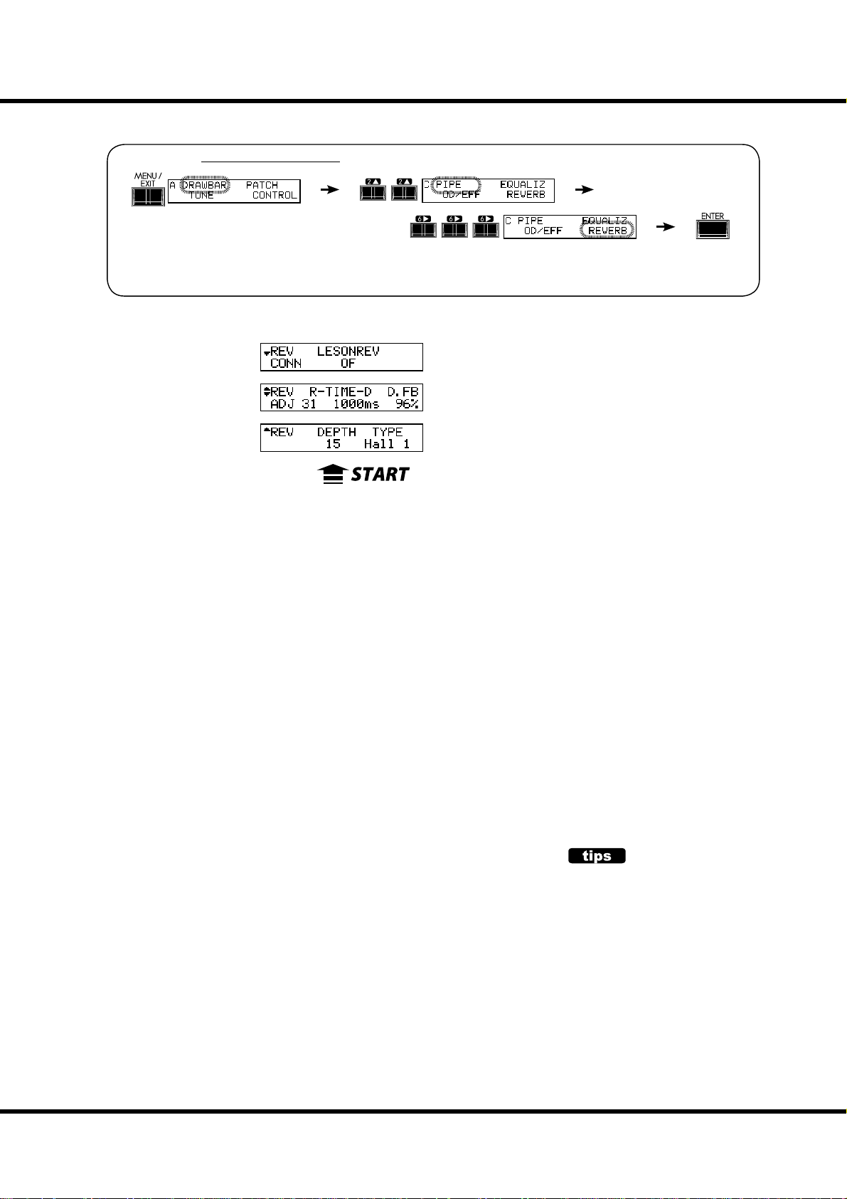
REVERB
In this mode, you set the Reverb eff ect.
To locate this mode:
or, keep pressing the [REVERB ON] button for a few seconds.
See “Function mode” (P. 62) for operation details.
❻
❸❹ ❺
❶ ❷
95
❶ DEPTH
is sets the depth (volume) of the Reverb Eff ect.
e setting range is 0 to 127.
❷ TYPE
is sets the types of Reverb eff ect.
Room 1: Small room
Room 2: Large room
Live: Ambient room
Hall 1: Large Hall
Hall 2: Small Hall
Church: Church
Plate: Iron-plate Reverb
Spring: Spring Reverb
Delay: Delay
PanDly: Panning Delay
RevDly: Reverb + Delay
❸ REVERB TIME
When the Type (#2) is set at Room 1 to Spring, e decay of the Reverb is attenuated.
e setting range is 0 to 127. e decay becomes greater as the value is increased.
❹ DELAY TIME
When the Type (#2) is set at Delay, PanDly, RevDly, this parameter sets the delay time.
e setting range is 4.7 to 2000ms. e delay becomes longer as the number value is
increased.
NOTE: You can set the delay time with the foot switch. (P. 72 #2)
❺ DELAY FEEDBACK
When the Type (#2) is at Delay, PanDly, RevDly, it sets the amount of Feedback (How
many times the sound repeats.)
e setting range is 0 to 96%. e repetition becomes greater as the value is increased.
NOTE: Type (#2) is a macro-parameter. When you change the type, each reverb parameter (#3 to
#5) is automatically set to the recommend value.
❻ LESLIE ON REVERB
is sets the routing of the Reverb eff ect.
OFF: Leslie to Reverb
ON: Reverb to Leslie
LESLIE ON REVERB
In the past when there are no electronic Leslie e ect, the sound sent to the Leslie speaker
with reverb e ect. It made a sound which rotated reverb too.
The Leslie On Reverb simulates that.
NOTE: All the parameters in these modes
are Patch Parameters. They are recorded into the Patch.
Setting the Parameters
Page 96

96
DEFAULT
In this mode, you can go back totally or partially to the factory default settings.
To locate this mode:
❼❺❻
❶ ❷❸ ❹
To initialize each parameter, select the parameter you want to initialize with the [W][X]
button and press the [ENTER] button.
❶ MANUAL
is is for initializing the contents of the [MANUAL] button.
Used to create a “clean slate” for new Patch settings.
❷ PATCH
is is for initializing the User Patch contents (from Preset Patch with same patch number). Select the Patch you want to initialize with the [VALUE] knob. e selecting range
is U1-1 to U8-8 and ALL (All user patches).
❸ GLOBAL
is is for initializing the Global Parameters such as the Master Tune or assignment of
the Foot Switch.
❹ LESLIE
is is for initializing the contents of all internal Leslie cabinets. Select the cabinet you
want to initialize with the [VALUE] knob. e selecting range is U1 to U8 and ALL (All
User cabinets).
❺ CUSTOM TONE-WHEELS
is is for initializing the contents of all custom Tone-Wheels.
❻ PIPE
is is for initializing the Pipe parameters.
❼ ALL
is is for initializing all parameters of this keyboard.
If any unstable condition occurs on this keyboard system, initializing “all” will usually
clear the problem.
NOTE: You can also totally initialize this keyboard by switching the power ON while pressing
and holding the [RECORD] button.
*#1 :-%
Owner’s Manual
Page 97

SYSTEM
In this mode,the audio output mode and the System information of the XK-1C is
displayed.
To locate this mode:
See “Function mode” (P. 62) for operation details.
97
❻❼
❷
❶
❶ AUDIO MODE - OUTPUT
❸❹❺
Sets the audio mode of output jacks.
STEREO
Use when this keyboard is connected in stereo. You can get the maximum stereophonic sound e ects.
MONO
Use when this keyboard is connected in mono. Though it makes no stereophonic sound e ects, it
avoids “drop out” by sounding opposite channel.
❷ VERSION - MAIN PROGRAM
❸ VERSION - SUB PROGRAM
❹ VERSION - VOICE INFORMATION
❺ VERSION - D. S. P.
❻ VERSION - BOOTSTRAP PROGRAM
❼ VERSION - FACTORY PRESET
❽ VERSION - CONTROL PANEL
ese are display only and not intended for System update use.
❽
Setting the Parameters
Page 98

98
*#1 :-%
Owner’s Manual
Page 99

99
MIDI
Page 100

100
ABOUT MIDI
WHAT IS “MIDI”?
MIDI is an acronym of ‘Musical Instrument Digital Interface’.
MIDI is the musical instrument industry standard for exchanging performance infor-
mation between electronic musical instruments and a sequencer, eff ects, lighting, and
sound reinforcement gear, etc.
e MIDI standard allows instruments made by diff erent manufacturers to eff ectively
communicate with each other.
Many types of data can be transmitted and received, including all performance information, settings of parameters, and global commands.
MIDI JACKS ON THIS KEYBOARD
USB
FLASH DRIVE
MIDI OUT JACK
is is sends performance information to an external MIDI sound module, or to
record performances and controls to an external sequencer.
MIDI IN JACK
is jack is used for playing this keyboard from external MIDI equipment.
WHAT THE MIDI CAN DO ON THIS KEYBOARD
On this keyboard, the MIDI terminals are intended to do the following:
Use a MIDI keyboard/pedalboard to expand the versatility of play.
Control an external sound generator such as a synthesizer or sampler.
Record/playback the performance on an external sequencer or computer.
For easier access to those settings, this keyboard is equipped with “MIDI Templates”.
*#1 :-%
Owner’s Manual
 Loading...