

Page 1
*#1 *#1
*#1
*#1 *#1
Model :-
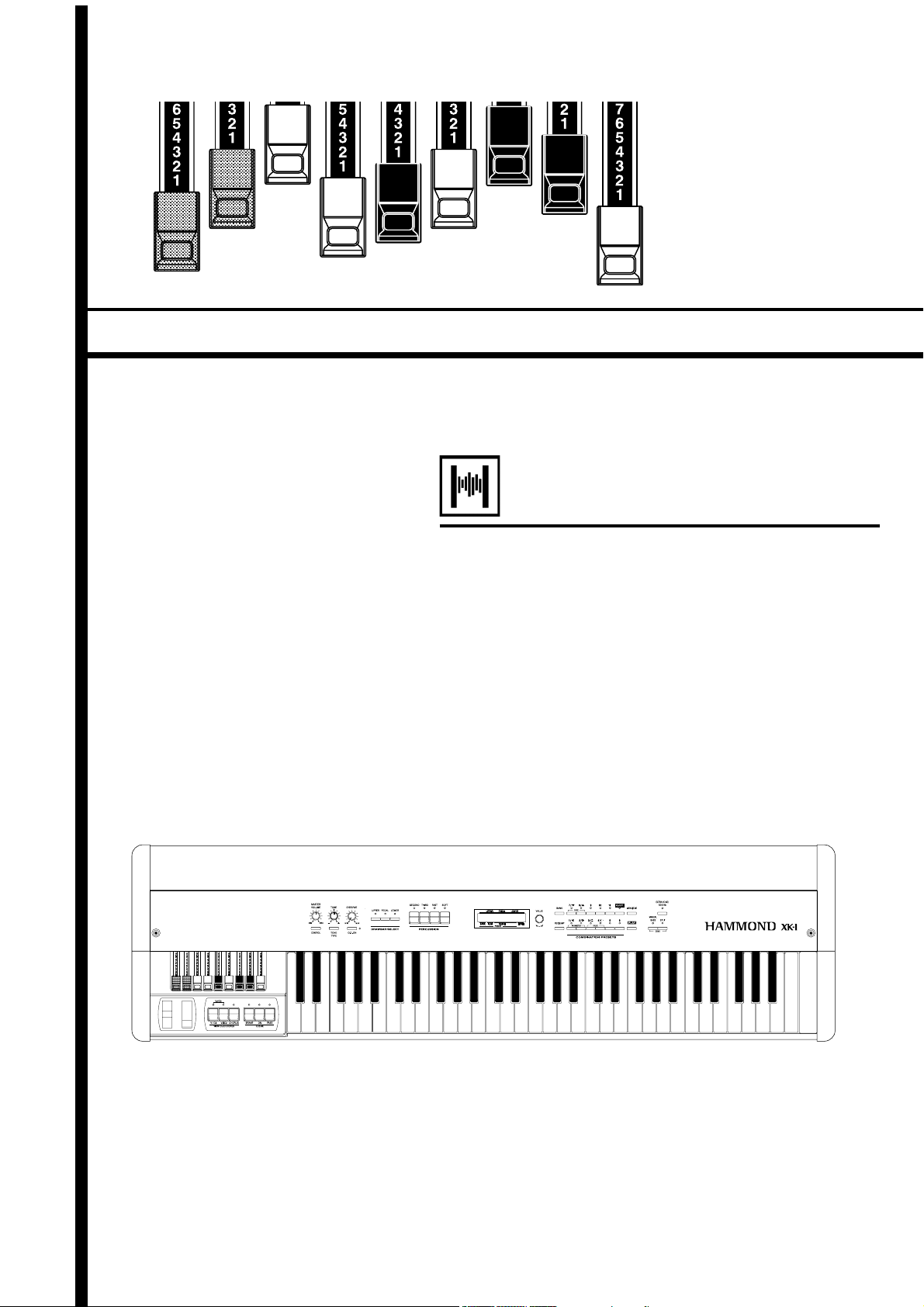
Thank you, and congratulations on your choice of
a Hammond XK-1.
In order to get the most out of this instrument for
many years to come, first take the time to read this
manual in full.
Owner’s Manual
Page 2
IMPORTANT SAFETY INSTRUCTIONS
Read these instructions.
Keep these instructions.
Heed all warnings.
Follow all instructions.
Do not use this apparatus near water.
Clean only with dry cloth.
Do not block any ventilation openings.
Install in accordance with the manufacturer's instructions.
Do not install near any heat sources such as radiators, heat
registers, stoves or other apparatus (including amplifiers) that
produce heat.
Do not defeat the safety purpose of the polarized or groundingtype plug. A polarized plug has two blades with one wider than
the other. A grounding type plug has two blades and a third
grounding prong. The wider blade or third prong is provided for
your safety. If the provided plug does not fit into your outlet,
consult an electrician for replacement of the obsolete outlet.
Protect the power cord from being walked on or pinched,
particularly at plugs, convenience receptacles, and the point
where they exit from the apparatus.
Only use attachments/accessories specified by the manufacturer.
Use only with the cart, stand, tripod,
bracket, or table specified by the
manufacturer, or sold with the
apparatus. When cart is used: use
caution when moving the cart/
apparatus combination to avoid
injury from tip-over.
Unplug this apparatus during lightning storms, or when
unused for long periods of time.
Refer all servicing to qualified service personnel. Servicing is
required when the apparatus has been damaged in any way,
such as power-supply cord or plug is damaged, liquid has
been spilled or objects have fallen into the apparatus, the
apparatus has been exposed to rain or moisture, does not
operate normally, or has been dropped.
Apparatus shall not be exposed to dripping or splashing and
no objects filled with liquids, such as vases, shall be placed
on the apparatus.
WARNING: To reduce the risk of fire or electric shock, do not
expose this apparatus to rain or moisture.
The lightning flash with arrowhead symbol within an equilateral
triangle, indicates that dangerous voltage constituting a risk of
electric shock is present within this unit.
The exclamation point witnin equilateral triangle, indicates that
there are important operating and maintenance instructions in
the literature accompanying this unit.
In case if in the future your instrument gets too old to play/use or
malfunctions beyond repair, please observe the instructions of
this mark, or, if any question, be sure to contact your dealer or
your nearest town or municipal office for its proper disposal.
*#1 :-Owner’s Manual
Page 3
FOR UNITED KINGDOM:
FOR YOUR SAFETY, PLEASE READ THE FOLLOWING TEXT CAREFULLY
This appliance is supplied with a molded 3-pin mains plug for your safety and convenience.
A 5 amp fuse is fitted in this plug.
Should the fuse need to be replaced, please ensure that the replacement fuse has a rating of 5
amps and that it is approved by ASTA or BSI to BSI1362.
Check for the ASTA mark or the BSI mark on the body of the fuse.
If the plug contains a removable fuse cover, you must ensure that it is refitted when the fuse is
replaced.
If the fuse is lost, the plug must not be used until a replacement cover is obtained.
A replacement fuse cover can be obtained from your local Hammond Dealer.
IF THE FITTED MOULDED PLUG IS UNSUITABLE FOR THE SOCKET OUTLET IN YOUR
HOME, THEN THE FUSE SHOULD BE REMOVED AND THE PLUG CUT OFF AND DIS-
POSED OF SAFELY.
THERE IS A DANGER OF SEVERE ELECTRICAL SHOCK IF THE CUT-OFF PLUG IS IN-
SERTED INTO ANY 13 AMP SOCKET.
If a new plug is to be fitted please observe the wiring code as shown below.
If in any doubt, please consult a qualified electrician.
IMPORTANT - The wires in this mains lead are coloured in accordance with the following code:
Blue: Neutral
Brown: Live
As the colours of the wires in the mains lead of this unit may not correspond with the coloured
marking identifying the terminals in your plug, proceed as follows.
The wire which is coloured BLUE must be connected to the terminal in the plug which is marked
with the letter N or coloured BLACK.
The wire which is coloured BROWN must be connected to the terminal in the plug which is marked
with the letter L or coloured RED.
Under no circumstances should either of these wires be connected to the earth terminal of the
three-pin plug, marked with the letter E or the Earth Symbol .
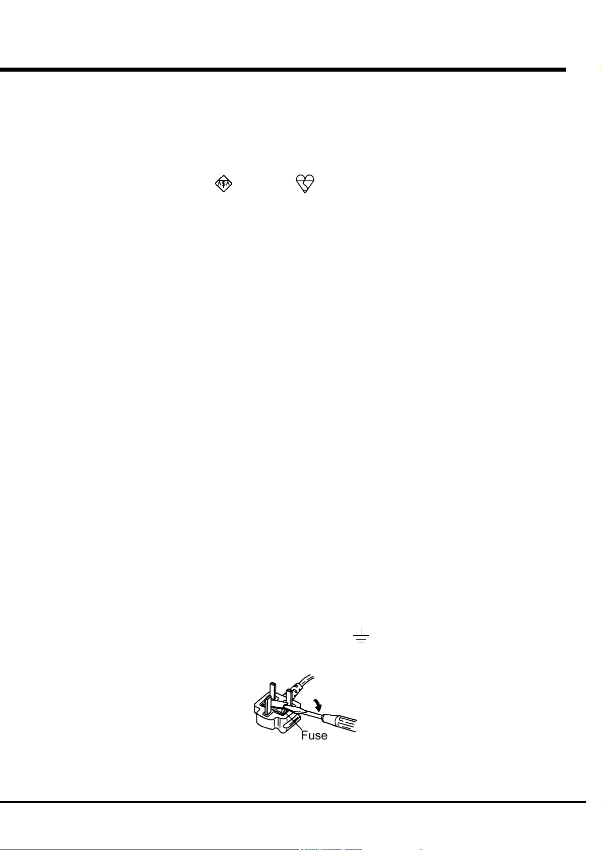
How to replace the fuse. Open the fuse compartment with a screwdriver and replace the fuse and
fuse cover.
Introduction
Page 4

IMPORTANT - PLEASE READ
Your Hammond XK-1 Drawbar Keyboard is designed to give you the true and
authentic sound of Hammond Harmonic Drawbars, as well as provide you a large
variety of features to allow great flexibility in how you want to use the keyboard.
This Owner's Manual is designed to explain the operating features of your Hammond
XK-1 as simply and graphically as possible.
Because we want to make this manual, as well as the keyboard itself, as easy to
understand as possible, the explanations in this manual are grouped by subject matter,
and not in the order in which they necessarily apper in the display (the screen in the
left of the keyboard front panel). For example, all functions pertaining to Drawbars
are grouped together, all Percussion features are treated as a group, and so on.
Also, each feature is treated as an explanation unto itself, and does not require you to
already have prior working knowledge of some other feature. The explanations are
presented such that, if you follow the steps, will be identical to that shown in the
manual at that stage of the explanation.
Do not be daunted by the number of steps required to perform each operation. Each
step is simple. Simply bear these things in mind:
1. Read each step carefully.
2. Don't skip any of the steps.
3. Don't perform the steps out of sequence.
With these guidelines, you are well on your way to mastering all of the many sounds
and features of your Hammond XK-1.
*#1 :-Owner’s Manual
Page 5
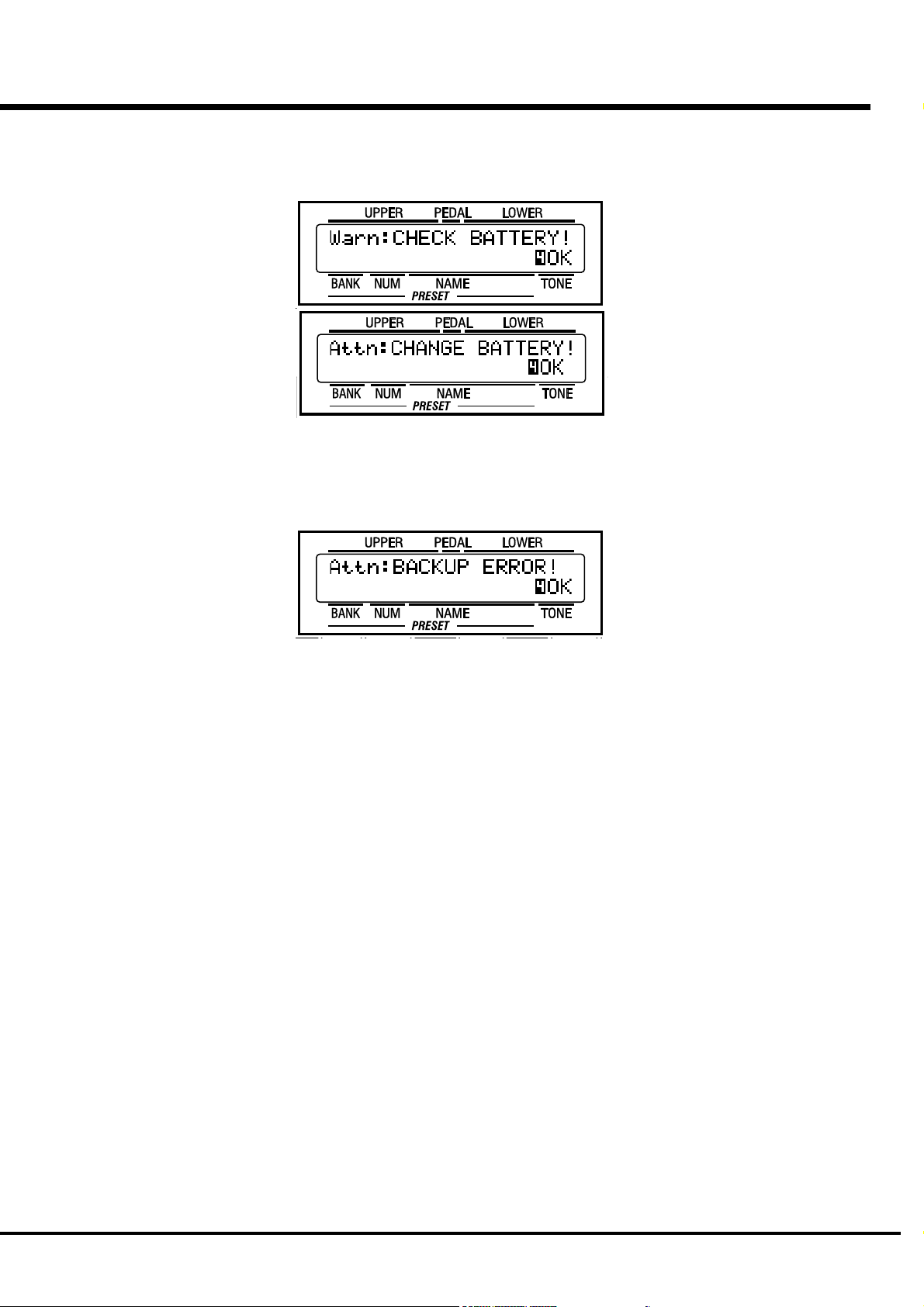
BATTERY BACK UP
Your XK-1 uses a battery-backed RAM to remember your changes to the Parameters.
When the battery voltage becomes low, the Display will show:
If you see these messages, you should immediately back up your parameter changes, if
you have made any. If there is no battery installed in the unit, or if the battery is
compeletely dead, the Display will show:
After the above message is displayed, the XK-1 will re-initialize itself, and the factory
default settings will be restored. Therefore, it is a good idea to periodically save your
data to CompactFlash card.
CAUTION: In order to change batteries, be sure to ask your dealer or store.
Introduction
Page 6

Table Of Contents
IMPORTANT SAFETY INSTRUCTIONS.................................. 2
IMPORTANT - PLEASE READ ............................................... 4
BATTERY BACK UP .............................................................. 5
MAIN FEATURES ................................................................. 9
NAMES AND FUNCTIONS .................................................. 10
Front Panel................................................................................... 10
End Block .................................................................................... 12
Rear Panel ................................................................................... 13
HOOK-UP........................................ 15
BASIC HOOK-UP ................................................................ 16
CONNECTING THE LESLIE SPEAKER ................................. 17
STANDARD HOOK-UP ............................................................. 17
USING MIDI CONTROL ............................................................ 17
CONNECTING THE MIDI KEYBOARD .................................. 18
TURN ON AND PLAY ...................... 19
POWER ON ........................................................................ 20
HOW TO POWER ON............................................................... 20
BACK-UP ................................................................................ 20
RESET TO THE FACTORY SETTINGS ...................................... 20
LISTEN TO THE DEMONSTRATION PERFORMANCE .......... 21
USING THE COMBINATION PRESETS ................................ 22
HOW TO RECALL THE PRESETS ............................................ 22
1.Selecting preset BANK .............................................................. 22
2.Selecting preset NUMBER ......................................................... 22
PLAY WITH THE CONTROLLERS ....................................... 23
PITCH BEND WHEEL ............................................................... 23
EXPRESSION PEDAL ............................................................... 23
FOOT SWITCH ........................................................................ 23
MAKING YOUR OWN SOUNDS .......................................... 24
TOUCH THE DRAWBAR SELECT [UPPER] .............................. 24
SELECT THE PRESET BUTTON [ADJUST] ............................... 24
PULL OUT THE DRAWBARS ................................................... 24
ADD PERCUSSION .................................................................. 24
ADD EFFECTS ......................................................................... 25
VIBRATO/CHORUS ....................................................................... 25
OVERDRIVE ................................................................................. 25
LESLIE ......................................................................................... 25
USING EXTRA VOICES ............................................................ 25
Divide the keyboard into two parts - left and right. [SPLIT] .... 26
Add bass part on the manual keyboard. [MANUAL BASS] ....... 26
What is “Part”? ....................................................................... 26
STORING REGISTRATIONS IN COMBINATION PRESET............ 27
EX. Memorize to “6 - 3”. ............................................................. 27
SETTING UP ................................... 29
SOUND ENGINE STRUCTURE ............................................ 30
SYSTEM STRUCTURE OF XK-1 KEYBOARD ............................ 30
DRAWBARS™ .................................................................... 32
WHITE DRAWBARS ................................................................ 33
BLACK DRAWBARS ................................................................ 33
BROWN DRAWBARS .............................................................. 33
PEDAL DRAWBARS ................................................................ 33
DRAWBAR REGISTRATION PATTERNS ................................... 34
DRAWBAR SELECT ............................................................ 36
ASSIGN THE DRAWBARS FOR EACH PART ............................ 36
MATCH THE REGISTRATION TO DRAWBARS.......................... 36
PERCUSSION ..................................................................... 37
NOTES .................................................................................... 37
“Percussion does not sound!” ..................................................... 37
DRAWBAR CANCEL ..................................................................... 37
VIBRATO/CHORUS............................................................. 38
OVERDRIVE ....................................................................... 39
LESLIE ............................................................................... 40
EQUALIZER & REVERB ...................................................... 41
EQUALIZER ............................................................................. 41
REVERB .................................................................................. 41
COMBINATION PRESETS ................................................... 42
BANK AND NUMBER ............................................................... 42
NAME THE COMBINATION PRESETS ...................................... 43
RECORD A NEW THE COMBINATION PRESET ........................ 44
USING THE CONTROL PANEL ...... 45
OPERATION CONTROL PANEL ........................................... 46
PLAY MODE ....................................................................... 47
HOW TO READ THE DISPLAY ................................................. 47
MENU MODE ..................................................................... 48
HOW TO READ THE DISPLAY ................................................. 48
BUTTON OPERATION IN THIS MENU....................................... 48
FUNCTION MODE .............................................................. 49
HOW TO READ THE DISPLAY ................................................. 49
BUTTON OPERATION IN THIS MODE....................................... 49
Example of operation .............................................................. 50
SHORT CUT TO THE FUNCTION MODE .............................. 52
Example of operation .............................................................. 52
STORING THE PAGE YOU FREQUENTLY USE .................... 52
Example of operation .............................................................. 52
*#1 :-Owner’s Manual
Page 7
SETTING THE PARAMETERS ....... 53
IN THIS MANUAL:
NOTE:s and appear frequently.
The NOTE: is a supplementary explanation.
The are explanations of terms and
applications.
DRAWBAR ......................................................................... 54
Setting the Manual (LOWER and UPPER) ................................................. 54
Setting the PEDAL .................................................................................... 55
PRESET ............................................................................. 56
PRESET NAME ......................................................................................... 56
PRESET LOAD .......................................................................................... 56
EFFECTIVE USE OF LINK-LOWER/PEDAL ................................ 57
WHEN LINK LOWER/PEDAL IS ON: .............................................. 57
WHEN LINK LOWER/PEDAL IS OFF: ............................................. 57
CONTROL........................................................................... 58
PITCH BEND ............................................................................................. 58
MODULATION ...........................................................................................59
EXPRESSION ............................................................................................ 59
FOOT SWITCH .......................................................................................... 60
EXTRA VOICE / REVERB ...........................................................................61
DISPLAY ...................................................................................................61
ADJUSTING THE EXPRESSION PEDAL .................................... 62
TUNE ................................................................................. 63
CUSTOM TONEWHEELS .................................................... 64
PERCUSS (PERCUSSion) .................................................. 65
LESLIE ............................................................................... 66
CABINET NUMBERS ................................................................................. 66
LESLIE PARAMETERS .............................................................................. 66
RECORD THE CABINETS ........................................................ 68
OD/VIB (OverDrive / VIBrato) ............................................ 69
OVERDRIVE .............................................................................................. 69
VIBRATO/CHORUS ................................................................................... 69
EQUALIZ (EQUALIZer) ....................................................... 70
REVERB ............................................................................. 71
DEFAULT ............................................................................ 72
SYSTEM ............................................................................ 73
EXVOICE (EXtra VOICE) ..................................................... 74
MIDI ................................................. 75
MIDI .................................................................................. 76
What is “MIDI”? ...................................................................... 76
MIDI TERMINALS ON THIS KEYBOARD ................................... 76
WHAT THE MIDI CAN DO ON YOUR KEYBOARD...................... 76
MIDI CHANNEL ............................................................................................ 77
MAJOR MIDI MESSAGE ..............................................................................77
CHANNEL MESSAGE ...................................................................................77
SYSTEM MESSAGE ..................................................................................... 77
MIDI STRUCTURE OF THIS KEYBOARD ............................. 78
KEYBOARD CHANNEL .............................................................................. 78
EXTERNAL ZONE CHANNEL ..................................................................... 78
EXPANDING THE KEYBOARD............................................. 79
RECORDING AND PLAYING ............................................... 80
Recording to the Sequencer or the Computer ........................... 80
Playback from the Sequencer or the Computer ......................... 80
CONTROLLING THE EXTERNAL MIDI EQUIPMENTS .......... 81
ZONES ............................................................................... 82
INTERNAL ZONE ....................................................................................... 82
EXTERNAL ZONE ...................................................................................... 82
MIDI .................................................................................. 84
MIDI TEMPLATE ....................................................................................... 84
MASTER ................................................................................................... 84
KEYBOARD CHANNEL .............................................................................. 85
TROUBLE SHOOTING ................... 87
TROUBLE SHOOTING ......................................................... 88
APPENDIX ...................................... 89
Custom Tone-wheel ........................................................... 90
MIDI Templates ................................................................. 91
Part and MIDI Messages ................................................... 93
MIDI Information ............................................................... 94
Drawbar Data List ............................................................. 95
System Exclusive Message ............................................... 96
Global Parameters ............................................................ 97
Bank Parameters ............................................................... 97
Preset Parameters ............................................................ 98
Leslie Parameters ........................................................... 100
System Parameters ......................................................... 100
Combi. and Bank/Program Messages ............................. 101
Specifications.................................................................. 102
Demonstration Songs and Composers ............................ 103
Factory Presets ............................................................... 104
SERVICE .......................................................................... 107
Introduction
Page 8

*#1 :-Owner’s Manual
Page 9

MAIN FEATURES
ACCURATELY REPRODUCES THE TONE-WHEEL SOUND.
Your new XK-1 contains (96) independent oscillating digital tone-wheels and accurately reproduces the
sound of the Vintage B-3.
In addition, this keyboard has full polyphony.
DIGITAL LESLIE / VIBRATO EFFECTS.
The XK-1 keyboard is equipped with a DSP effect generator to simulate the Scanner-Vibrato and Leslie
Speaker.
The range of sounds that you can create is expanded by the use of Vibrato and Chorus effects, and by the
real sounding Leslie effects which effectively simulates the rotation of the two Rotors which are present in
traditional Leslie.
8-PIN LESLIE SPEAKER SOCKET.
Your new XK-1 contains a 8-pin Leslie speaker socket for direct connection to Leslie 21 System Speakers.
BUILT-IN EXTRA VOICE.
This keyboard has built-in 8 Extra Voices such as Electric Piano and Clavi., to which you can switch from
Drawbar voices or Percussion voices.
9
CAN BE EXPANDED BY USE OF EXTERNAL MIDI PRODUCTS.
You can expand your keyboard by connecting and playing with additional external MIDI equipment.
This includes keyboards, sequencers, etc.
LIGHT WEIGHT AND COMPACT BODY.
The XK-1 is light and compact, but sounds and functions like deluxe model.
Introduction
Page 10
10
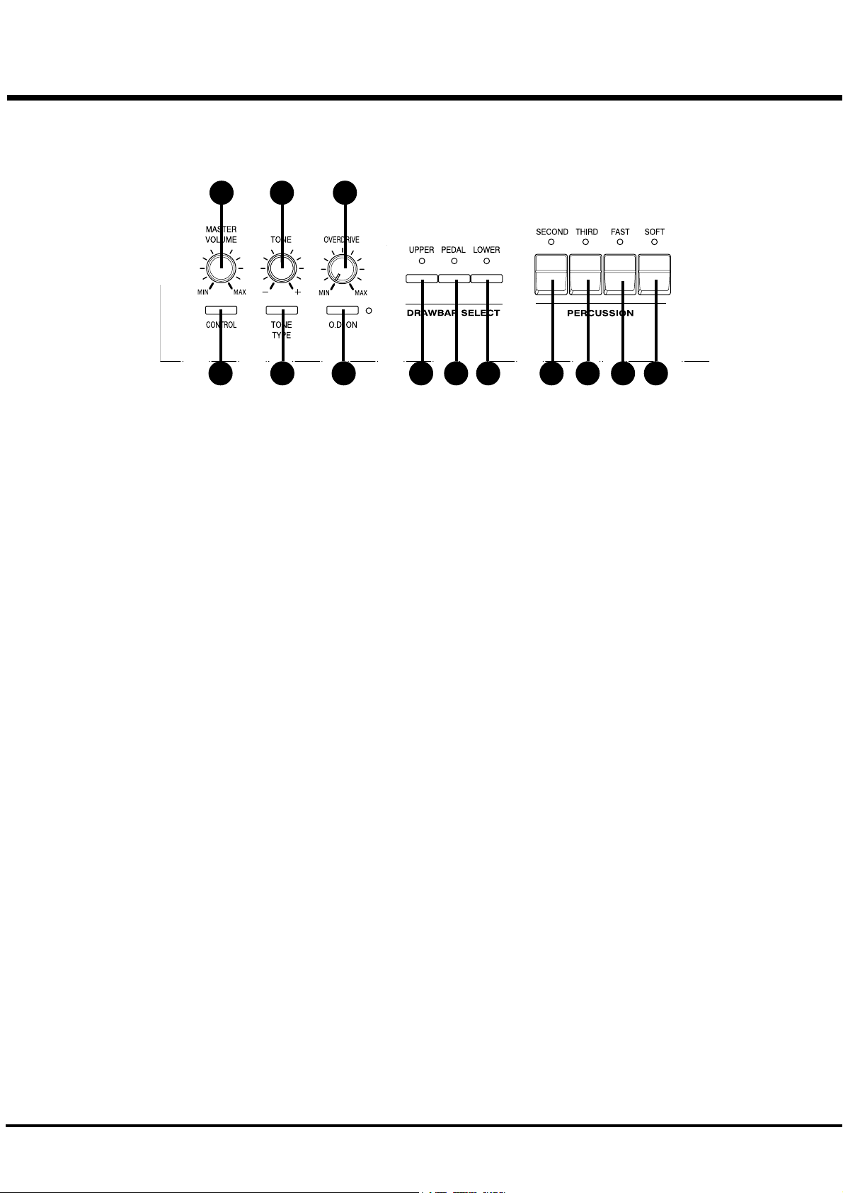
Front Panel
NAMES AND FUNCTIONS
1 3 5
9 10 12112 4 6 7 8 13
UPPER LEFT
1. MASTER VOLUME Knob
Controls the total volume.
2. CONTROL Button
Sets up various controls.
3. TONE Knob
Controls the tone quality.
4. TONE TYPE Button
Assigns the function of TONE CONTROL (3).
5. OVERDRIVE Knob
Controls the distortion of the Upper and Lower part.
6. O.D. ON Button
Switches the overdrive effect On / Off.
DRAWBAR SELECT
7. UPPER Button
8. PEDAL Button
PERCUSSION
10. SECOND Button
Adds 4' Percussion (Decay sound) to UPPER part.
11. THIRD Button
Adds 2 2/3' Percussion (Decay sound) to UPPER part.
12. FAST Button
Changes Decay time of Percussion.
13. SOFT Button
Changes Percussion volume.
9. LOWER Button
These buttons select which part of the registration. The
drawbars(27) will be active.
*#1 :-Owner’s Manual
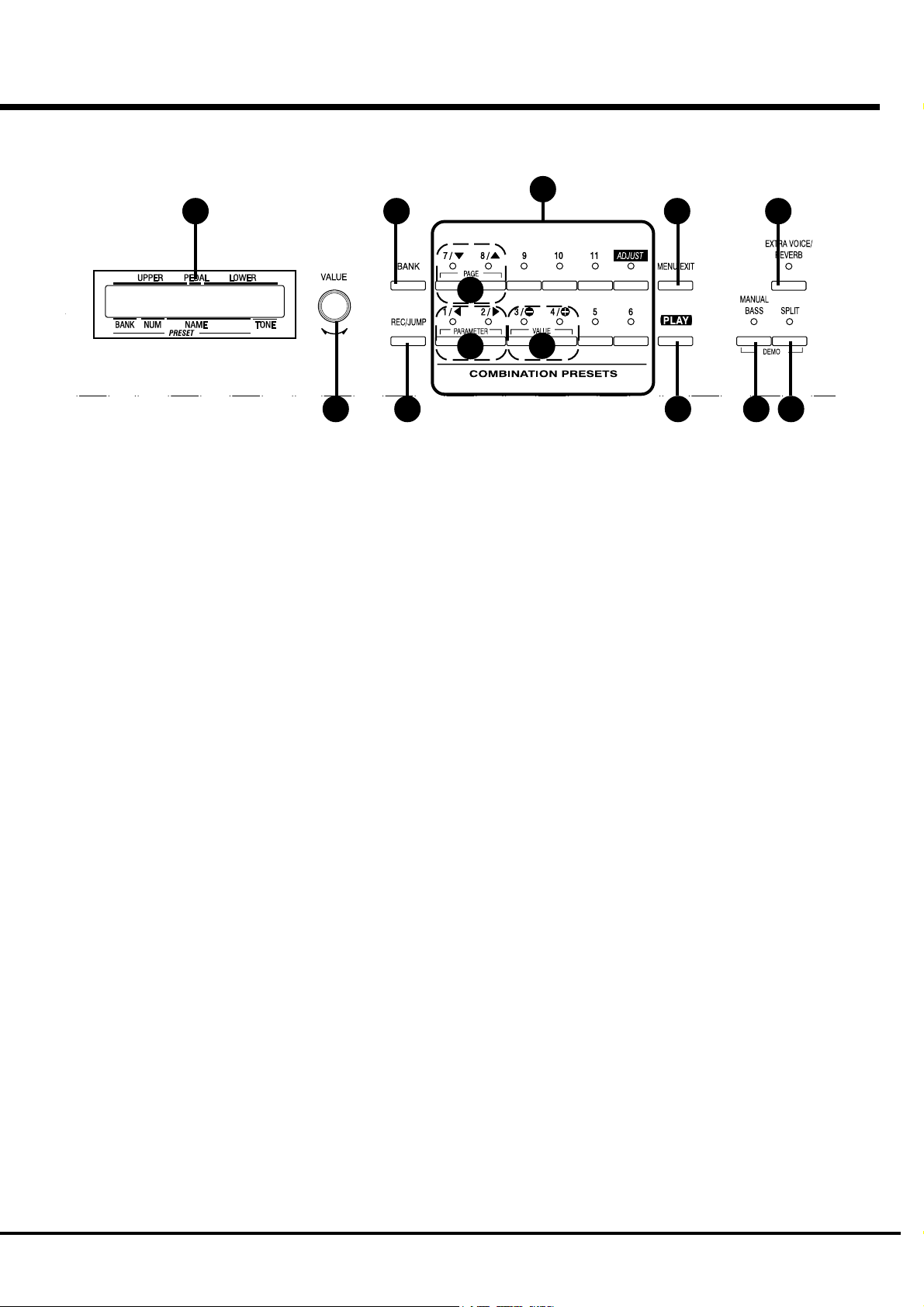
Page 11
14
16
19
18
22
11
26
15
17
CONTROL PANEL
14. DISPLAY
Displays various information.
15. VALUE Knob
Adjusts the value of selected parameter.
16. BANK Button
Selects the BANK of the Combination Presets. To select
the bank, Touch a Combination Preset button while
holding the BANK button.
17. REC/JUMP Button
Records Presets. This is also used to allow you to quickly
page through the various choices within each function.
20
21
23
UPPER RIGHT
24. MANUAL BASS Button
Allows Pedal sound to be played from the lowest notes
on the manual keyboard.
25. SPLIT Button
Divides the keyboard into two parts: UPPER and
LOWER.
26. EXTRA VOICE / REVERB Button
Switches On / Off the Extra Voice, Reverb effect etc.
(assignable)
24 25
18. Combination Presets
Select the NUMBER of the Combination Preset. These
buttons are also used for the PAGE, PARAMETER and
VALUE functions listed below.
19. PAGE Buttons
Selects Pages in the menu.
20. PARAMETER Buttons
Selects Parameters.
21. VALUE Buttons
Increases and decreases the value of selected parameter.
22. MENU/EXIT Button
Recalls the MENU screen. This is also used to return
from each function screen.
23. PLAY Button
Jumps to the PLAY screen, the basic screen.
Introduction
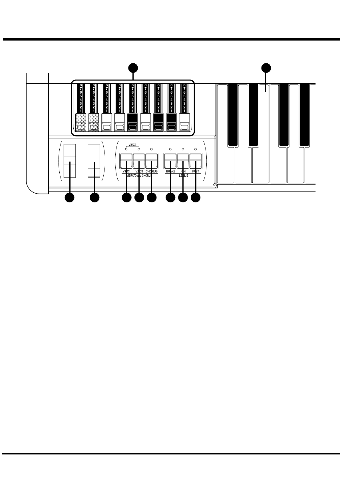
Page 12
12
End Block
DRAWBARS
27
28 29 30 31 3332 34 35
LESLIE
36
27. DRAWBARS
Controls harmonics of part that is selected by DRAW-
BAR SELECT (7 - 9). The setting of the Drawbars is
called a “Registration”.
WHEEL
28. PITCH BEND Wheel
Slides the pitch up or down.
The pitch goes up when moved up, and goes down when
moved down.
29. MODULATION Wheel
On this keyboard, this is used mainly to send MIDI
information to connected MIDI equipment, to add effect
to Extra Voice.
VIBRATO/CHORUS
30. V1/C1 Button
31. V2/C2 Button
Controls the depth of Vibrato / Chorus Effects on the
Upper and Lower parts. V1 is light effect, V2 is medium,
and the V3 (both V1 and V2 are On) is heavy.
33. LESLIE BRAKE Button
This button selects whether to produce sound from the
stopped rotor (=Brake) or not to use the Leslie effect (=
Through) when the LESLIE ON(34) Button is “Off”.
Brake is ON when the LED is on.
34. LESLIE ON Button
When it is turned ON, the rotor turns and the sound come
from the Rotor.
When the lamp is lighting, it is “ON”.
35. LESLIE FAST Button
Changes the speed of the Rotor from Slow to Fast.
It is FAST when the LED is ON.
KEYBOARD
38. MANUAL KEYBOARD
This keyboard contains 61 waterfall shaped keys.
Keyboard is velocity sensitive.
32. CHORUS Button
Switch from Vibrato or Chorus effect. When the LED is
ON, the Chorus effect is “ON”.
*#1 :-Owner’s Manual
Page 13
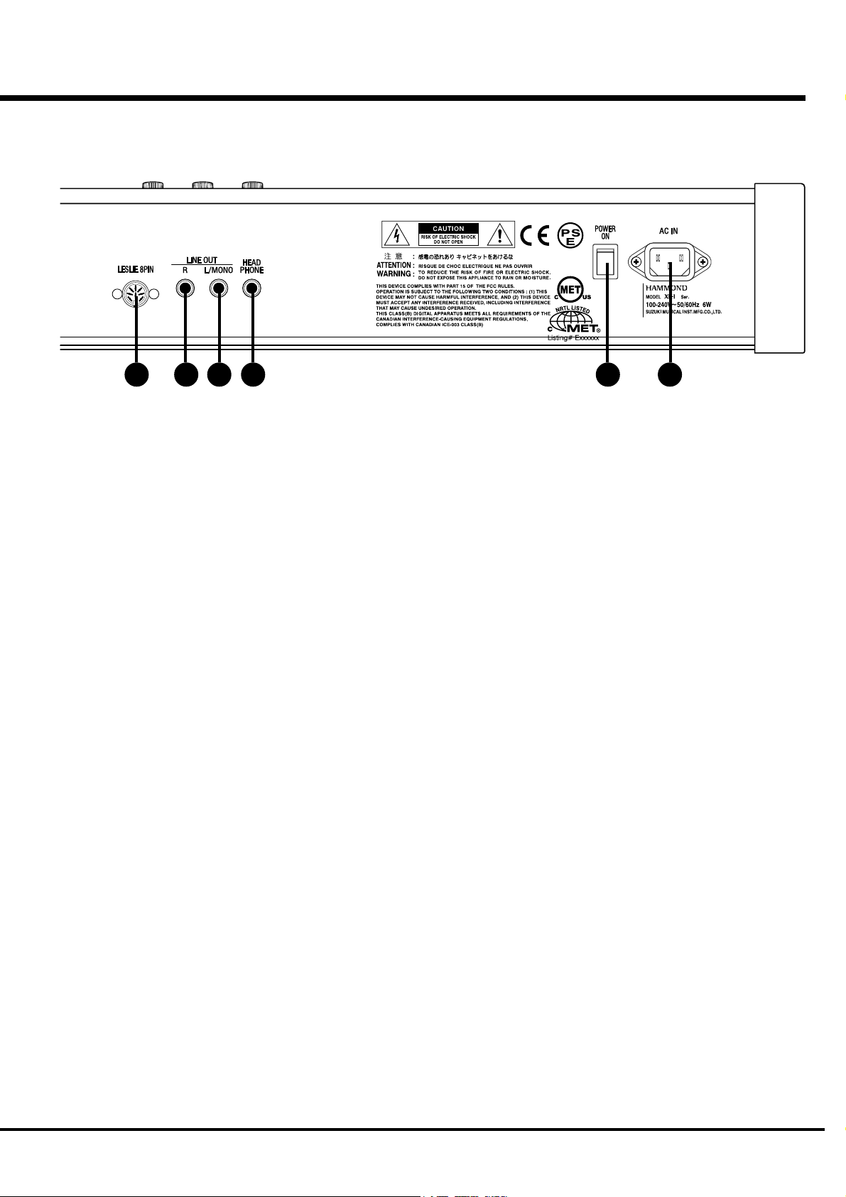
Rear Panel
13
37384142 3940
POWER SUPPLY
37. AC Inlet
Connects the A.C. Power Cable.
38. POWER Switch
This switches on and off the keyboard.
SOUND OUTPUT TERMINAL
39. LINE OUT L/MONO Jack
If your amplifier has only a single (1) female 1/4" audio
input connector (MONO input), use this Jack.
40. LINE OUT R Jack
This is the Right channel output of the XK-1.
Use the Left and Right output Jacks if your mixer or
amplifier has stereo input.
Use only the L/MONO terminal, if the input is monaural.
The built-in Leslie Effect is only on L (the left), when the
Leslie Speaker (42) is connected.
41. HEADPHONE Jack
This is for connecting a stereo headphones.
Sound is sent out from the LINE-OUTS (39, 40) and
LESLIE 8PIN (42), also when this terminal is used.
The built-in LESLIE is only on L (the left), when the
LESLIE SPEAKER (42) is connected.
42. LESLIE 8PIN Jack
This is for connecting the Leslie 21 System Speaker.
Read “CONNECTING THE LESLIE SPEAKER” for
more details.
Introduction
Page 14
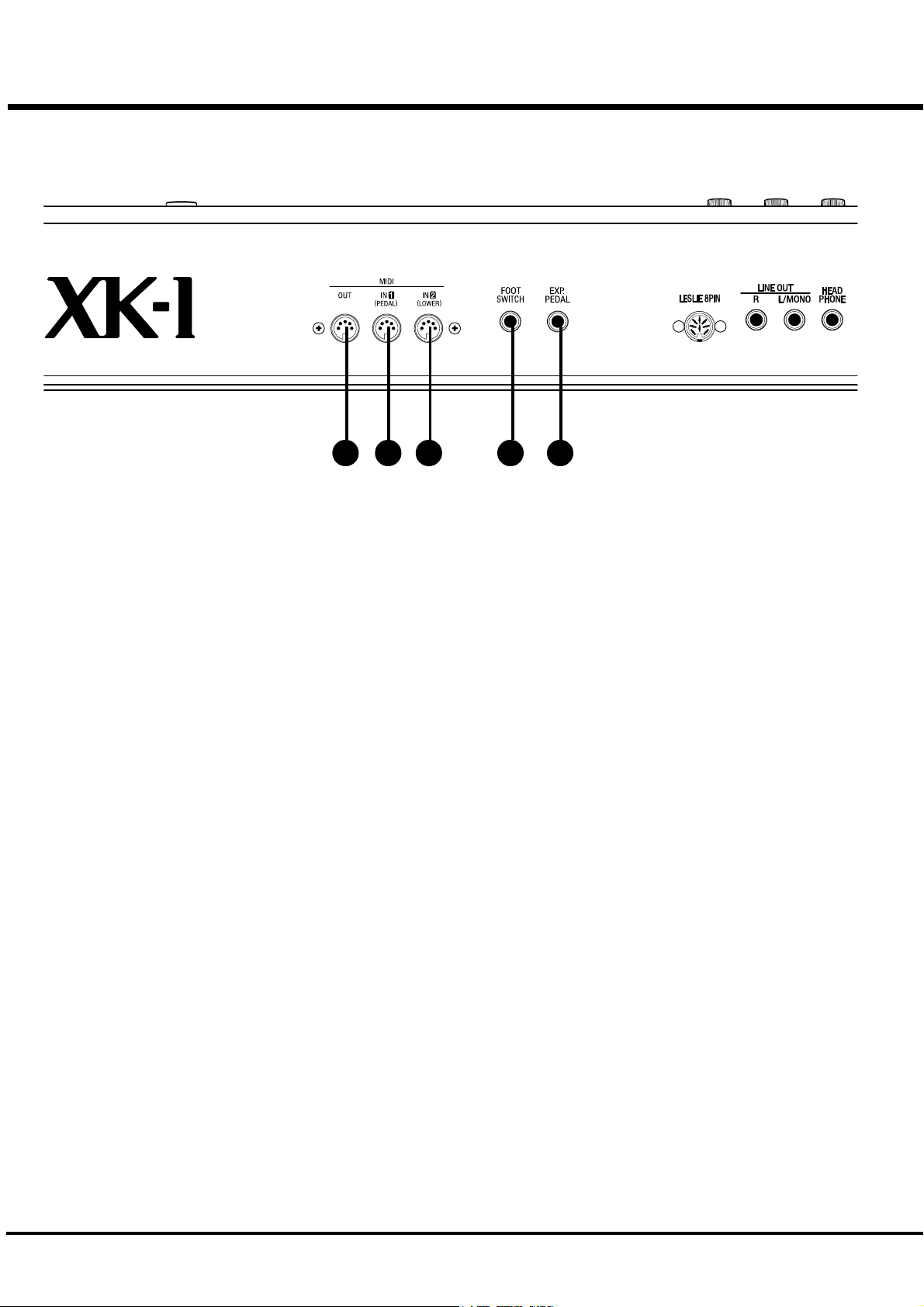
14
434445 46 47
MIDI TERMINAL
43. MIDI OUT Jack
Sends out the performance information of this keyboard.
44. MIDI IN 1(PEDAL) Jack
This is the MIDI IN Terminal used mainly for the Pedal
Keyboard.
[The factory setting] The MIDI information received by
channel. You can set that through this terminal functions
as PEDAL, regardless of the channel.
45. MIDI IN 2(LOWER) Jack
This is the MIDI IN Terminal used mainly for the Lower
Keyboard.
[The factory setting] The MIDI information received by
channel. You can set that through this terminal functions
as LOWER, regardless of the channel.
CONTROLLER TERMINAL
46. FOOT SWITCH Jack
This terminal is for the Foot Switch (FS-9H - optional).
You can switch the speed of the Leslie effect and the
Combination Preset, etc. while playing.
47. EXP. PEDAL Jack
This terminal is for the Expression Pedal (V-20R -
optional.)
You can control the volume while you play.
*#1 :-Owner’s Manual
Page 15

HOOK-UP
15
*#1 :-Owner’s Manual
Page 16
16
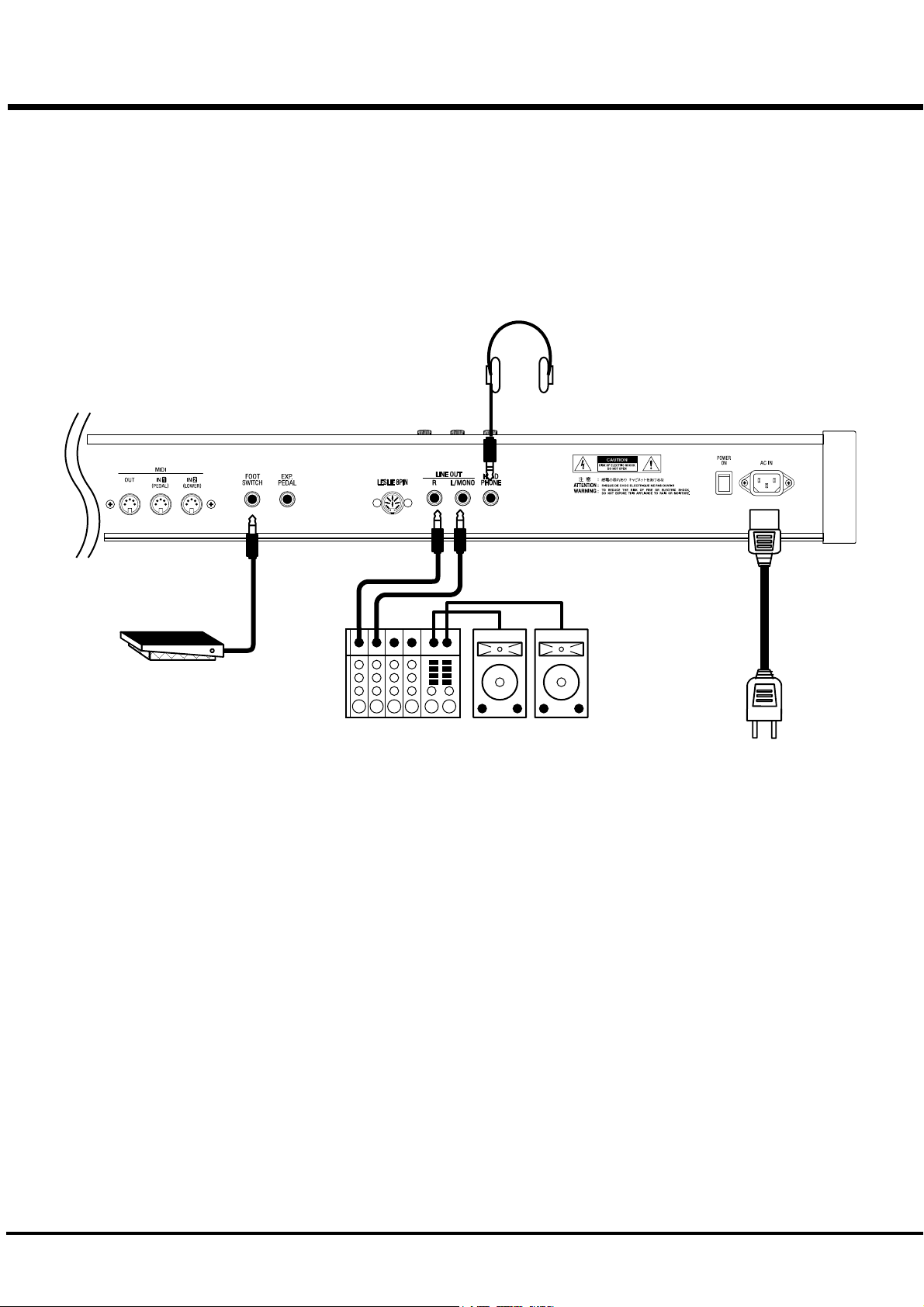
BASIC HOOK-UP
See the figure below for connection.
Amplifiers or speakers are not mounted in this keyboard.
You must connect an external amplifiers and speakers (or Powerd Speaker) in order
to hear the keyboard sounds.
You can also enjoy playing this keyboard by connecting Stereo Headphones to the
Headphone Jack.
Be sure to make the connection with the Power OFF on this keyboard and all con-
nected equipment.
Stereo
Headphones
Foot Switch FS-9H
(optional)
AC Power Cable
(provided)
Amplifier, Speakers etc.
*#1 :-Owner’s Manual
Page 17
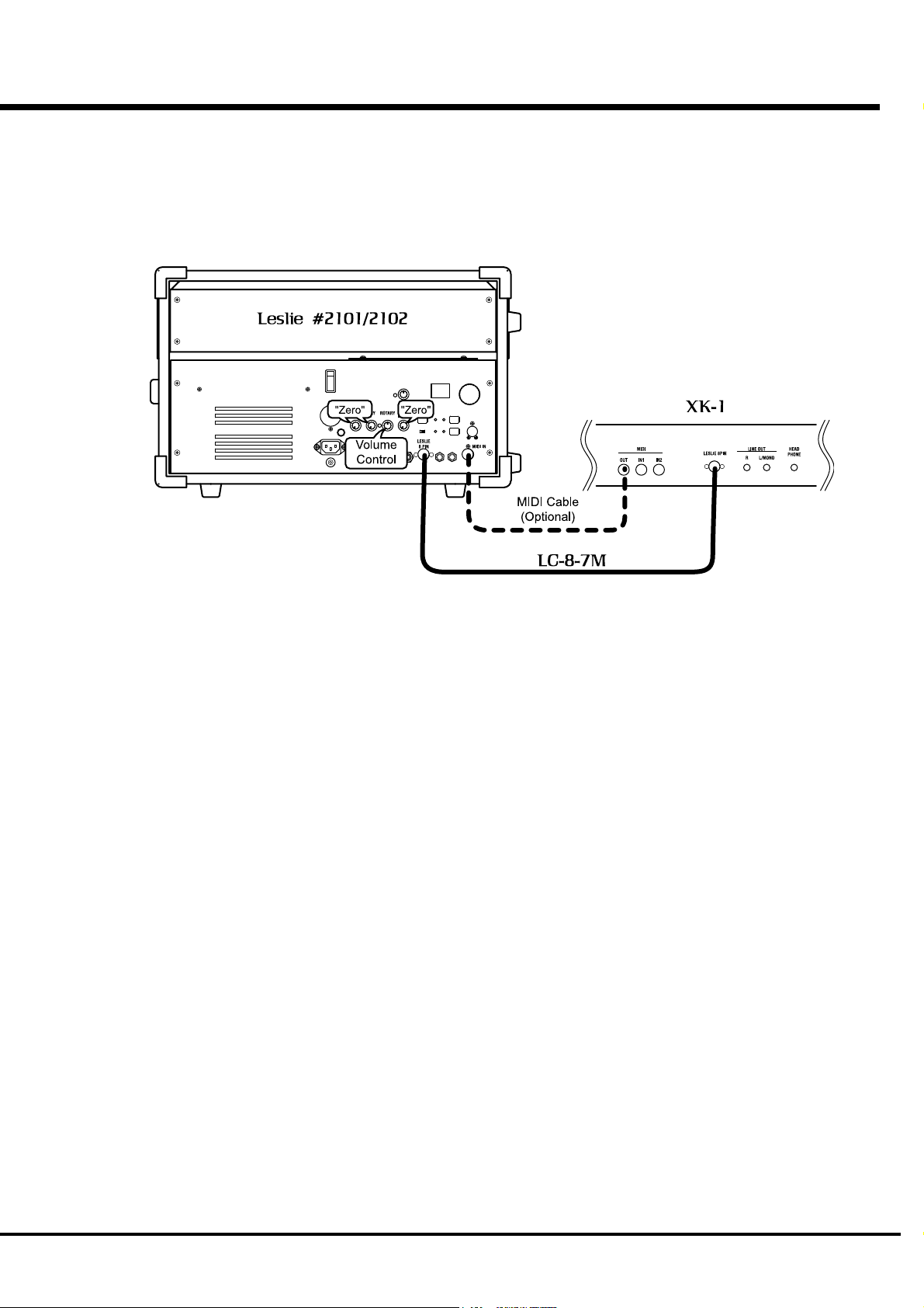
CONNECTING THE LESLIE SPEAKER
This keyboard is equipped with a 8-Pin Leslie Connector, so you can di-
rectly connect the Leslie 21 System Speaker.
Make this connection with switch power OFF on the equipment.
17
STANDARD HOOK-UP
Connect the Leslie Speaker to the 8-Pin Jack on the keyboard, with the
exclusive 8-Pin Leslie Cable (LC-8-7M - to be separately purchased - with the
other Leslie Speaker accessories).
Note: 8-Pin Jack is mouted. This keyboard can not use 11-pin Leslie speakers.
To control the volume of Leslie Speaker #2101/2102, use ROTARY Knob. Set
the STATIONARY konb for minimum. Because this keyboard has 1 channel
(rotary) audio circuit for the Leslie Speaker.
Please carefully read the User's Guide of the Leslie Speaker.
USING MIDI CONTROL
To control the parameters of the Leslie 21 System Speaker (i.e. finely adjust
the rotor, rise time etc.) using this keyboard, follow below instructions;
1. Connect the MIDI OUT of this keyboard and MIDI IN of the Leslie Speaker by
MIDI cable.
2. Set thc Keyboard Channel - Upper of this keyboard and MIDI Channel of the
Leslie Speaker to same channel. (P. 85)
3. Set the MIDI - Leslie Parameter to “21”. (P. 84)
Hook-Up
Page 18
18
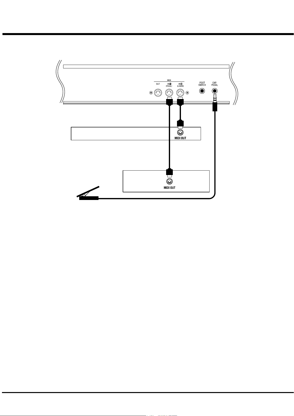
CONNECTING THE MIDI KEYBOARD
You can upgrade this keyboard to an organ by connecting an external MIDI Key-
board and pedal keyboard.
MIDI Keyboard
Expression Pedal
V-20R
1. Hook-up external MIDI keyboard and pedal keyboard per the figure above.
2. Use the MIDI Template “Seq. Record” of this keyboard. (P. 84)
3. To use Expression Pedal, set the parameter “EXPRESSION SOURCE” for the model of
expression pedal that you have connected. (P. 59)
The MIDI Keyboard connected to the PEDAL Terminal functions as the PEDAL
(part), and the one connected to the LOWER Terminal as the LOWER (part).
Please also read the User's Guide of the connected MIDI Keybaord.
MIDI Pedal
Keyboard
*#1 :-Owner’s Manual
Page 19

TURN ON AND PLAY
19
*#1 :-Owner’s Manual
Page 20
20
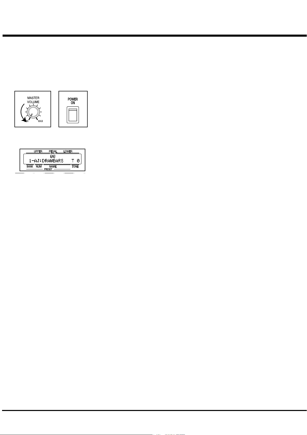
HOW TO POWER ON
After connecting your XK-1 to the power outlet, please perform the following steps before switch-
ing on the power. To avoid possible damages to speakers, please do not change the order of the
steps.
STEPS TO TAKE
1. Set the MASTER VOLUME Knob at 0 (minimum), before switching the power on.
2. Switch on the POWER on the rear panel. “PLAY” Mode appears, following the TITLE, in the
It takes a few seconds before the XK-1 gets ready, because of the circuit-protection
3. Switch on the power of the amplifiers etc. connected to the XK-1.
4. Holding down a key, adjust the MASTER VOLUME by turning the Knob.
5. Adjust the volume of the amplifiers etc.
Reverse the above steps when you switch off the power. (Switch off the power of
POWER ON
Display window.
devices.
the amplifiers etc. first.)
BACK-UP
Your XK-1 memorizes the setting of the keyboard immediately before it is switched off. So, The
keyboard will start with these settings when it is switched on again. This is called “Back-up”.
The XK-1 is initially shipped from the factory with the Preset Button [ADJUST] in “pressed”
status.
The Preset Button [ADJUST] does not produce sound when initially first turned on.
Draw the left Drawbar(s), or press either of the Preset Buttons [2] - [11] to start.
RESET TO THE FACTORY SETTINGS
Please perform the following steps to reset the XK-1 to the initial default setting.
STEPS TO TAKE
1. Switch off the power of the XK-1.
2. Hold the [REC/JUMP] Button, and switch on the power.
3. Continue to hold down / Keep pressing the [REC/JUMP] Button until “Loading Default...”
appears on the Display.
4. After 5 seconds if everything is in order, PLAY Mode appears on the Display. (Completed)
*#1 :-Owner’s Manual
Page 21
STEPS
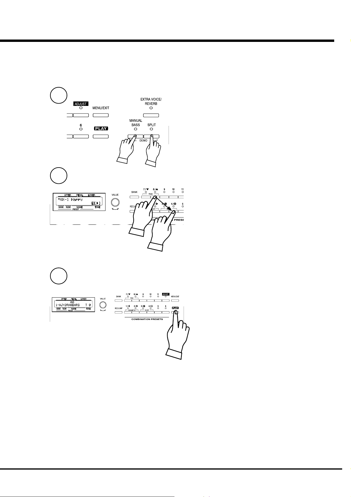
LISTEN TO THE DEMONSTRATION PERFORMANCE
In your XK-1, the demonstration performance is built in for introducing the
features and sound.
1
Touch and hold the [MANUAL BASS] and [SPLIT] Button for
2 seconds.
The Display will be as shown step 2.
NOTE: You can locate this mode another way. Touch the
[MENU] Button to display the MENU, touch the
[PAGE] Button and select page E, and touch the
[2]DEMO.
21
2
3
Press the [PAGE] Button and select a desired song.
The performance starts when the [4]“X” Button is pressed.
NOTE: After the song is over, the next one starts auto-
matically.
To select a new song while you are playing, touch the [4]“X”
Button again. The performance that is playing will stop.
NOTE: You can not operate the controllers while playing
the demonstration, except [MASTER VOLUME],
[LESLIE BRAKE], [LESLIE ON], [LESLIE FAST],
and [VIBRATO & CHORUS].
If you press the [MANUAL BASS] and [SPLIT](holding 2
seconds), [MENU/EXIT] or [PLAY] Button, the performance
stops.
Turn On and Play
Page 22
22
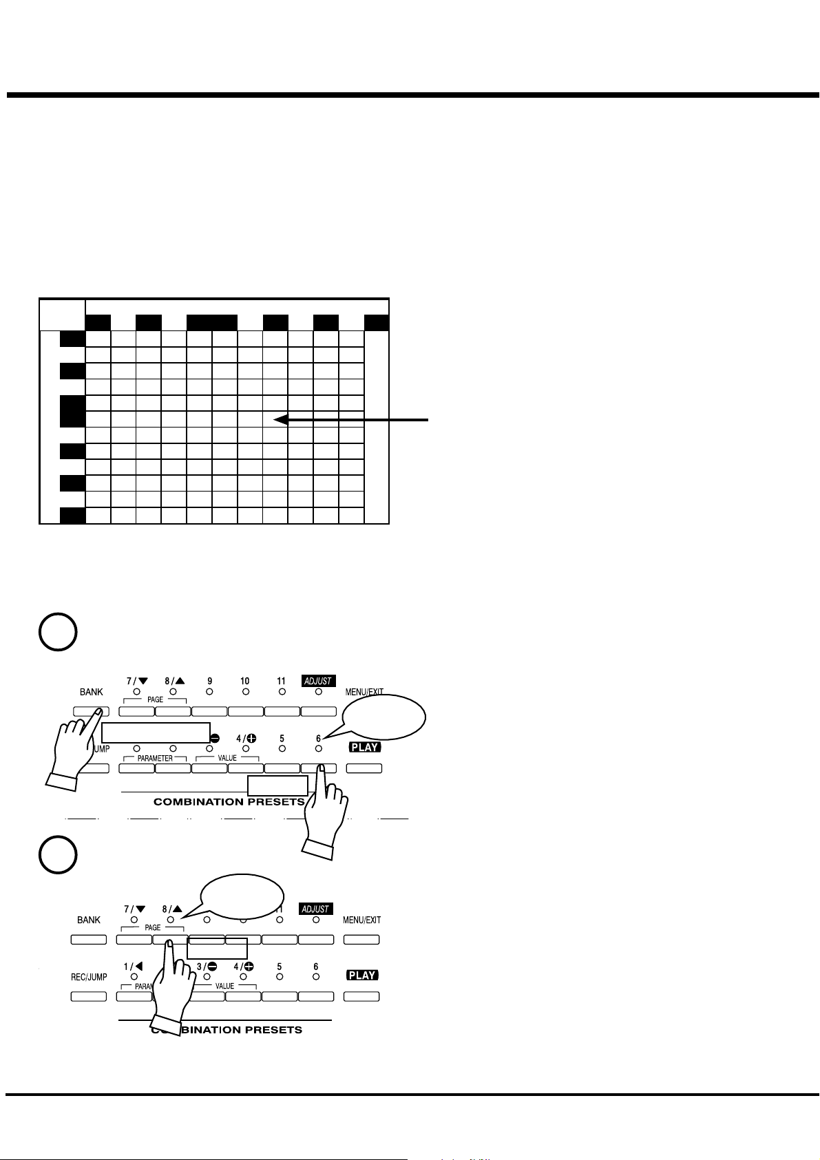
USING THE COMBINATION PRESETS
You can record various settings to the Preset Buttons
mounted on the right-hand side of the XK-1. This is
called “Combination Preset”.
The Combination Preset consists of the “BANK” and the
preset “NUMBER”, and Such as “1 - 3” appears for each
setting on the Display. The first letter is Bank and the
Combination Presets
Number
1 2 3 4 567 8 9 10 11 Ad
1
2
3
4
5
Bank
6
7
8
9
10
11
12
Adjust
second is Number.
The Preset data is recorded in the Banks 1 to 12 at the
factory. Thus you can start playing immediately.
The chart on the left is for the Combination Preset. The
“BANK” is shown vertically (line) and the “NUMBER”
horizontally (column). Select one combination from this chart
and play.
“1 - ADJUST” is initially selected at the factory.
The example below recalls this.
NOTE: The Preset Button “1” creates no sound (, if
combined) with any Bank in default. This is called
“Cancel”.
HOW TO RECALL THE PRESETS
EX. Select “6 - 8”
1
Light
Press and Hold
Touch
2
Light
Touch
1. Selecting preset BANK
While holding down the [BANK] Button, touch the Preset
Button [6].
NOTE: The LED for the Preset Button indicates the
“BANK”, while the [BANK] Button is pressed.
2. Selecting preset NUMBER
Touch the Preset Button [8].
At this time the Preset is selected and the setting changes.
NOTE: While the [BANK] Button is released, the LED
indicates the “NUMBER”.
“6 - 8” appears on the bottom left of the Display.
Recall various Combination Presets and play.
When you recall a Combination Preset, not only Drawbars but
also the Effects such as Leslie and Reverb change altogether.
However, the BANK 12 of the factory setting changes only the
Drawbars. This action is the same as on B-3 or C-3.
NOTE: You can set the types of the Parameter you recall.
(P. 56)
*#1 :-Owner’s Manual
Page 23

PLAY WITH THE CONTROLLERS
Your performance will be more expressive, if you play using the controllers.
You will see on this page how to use the controllers generally used with the
electronic musical instruments. (How to use the exclusive Hammond Organ
controllers is shown on the next page.)
PITCH BEND WHEEL
23
This is used to slide the pitch up or down while playing.
The frequency goes up when you move it back, and it goes down when you
move it forward.
When you release your hand from the PITCH BEND wheel, it returns auto-
matically to the center position.
NOTE: You can adjust the value of the wheel change. (P. 58)
The [MODULATION WHEEL] on the right is not usually used. It is used
when you transmit the modulation information to external MIDI equipment
(P.83), or to add effect to Extra Voice (P. 74).
EXPRESSION PEDAL
Fig.: V-20R (optional)
FOOT SWITCH
Generally, organs can not express dynamics or the velocity of the key touch.
However, if you connect the Expression Pedal to the organ, you can express
the velocity, corresponding to the degree of your foot-pressure on the pedal,
and add intonation to make your music more expressive. [The Expression
Pedal is to be separately purchased.]
The volume is loudest when you fully press down by means of your toe, and it
is quietest when you fully press down by means of your heel.
NOTE: Set the parameter at “Expression source” for the model of
expression pedal that you have conneted. (P. 59)
This switch is used to operate and control the organ by your foot instead of
pressing various switches by your hand while playing. [The Foot Switch is to
be separately purchased.]
The initial factory assignment is “LESLIE FAST”.
NOTE: You can change the Foot switch assignment. (P. 60)
Fig.: FS-9H (optional)
Turn On and Play
Page 24
24
MAKING YOUR OWN SOUNDS
You will be able to freely produce your own sound by using the exclusive features
of your HAMMOND ORGAN, such as Drawbars and Percussion sound, as well as
Vibrato and the Leslie effects. The steps to take are as follows:
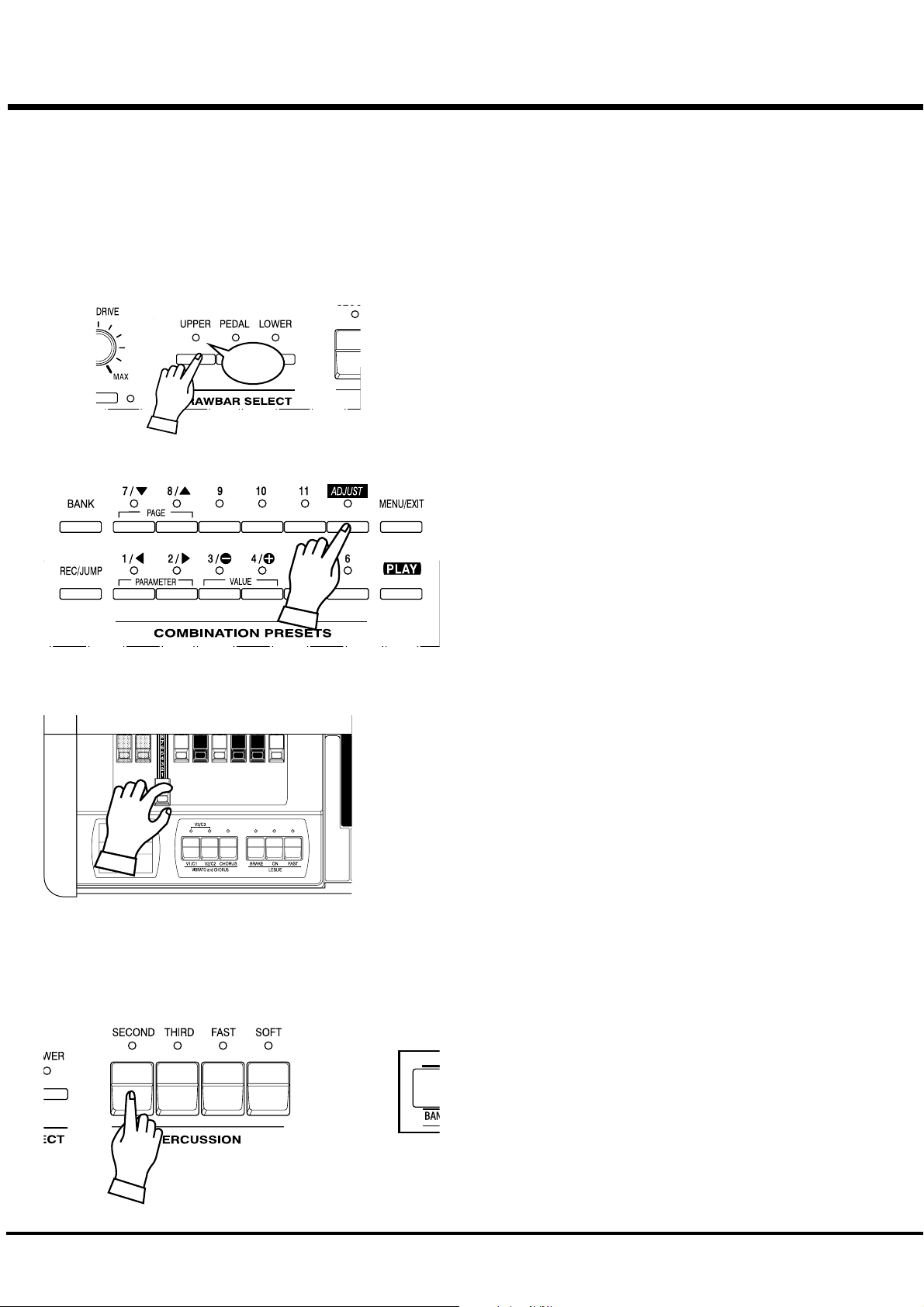
TOUCH THE DRAWBAR SELECT [UPPER]
Select the button [UPPER] of Drawbar Select.
These buttons allows to control the drawbar resistration each Part
Light
by drawbars which mouted on left side of the keyboard.
Note: What is “Part”? (P. 26)
Touch the [UPPER] this time, it is mostly used.
SELECT THE PRESET BUTTON [ADJUST]
Select the Preset Button [ADJUST].
This is a special button, also called “Adjust Preset”. While this
button is selected, your setting is always memorized, and the
Drawbar registration on the panel (= the length of the Drawbars)
always corresponds with the internal registration.
NOTE: You can initialize the contents to the default setting.
(P. 72)
PULL OUT THE DRAWBARS
Pull out the Left Drawbars on the left-hand side to your desired length, while
pressing a key on the keyboard.
The tone varies corresponding to the extent or the length of the Drawbar. So it is
the Drawbars that make the fundamental tones of this keyboard.
The volume gets loudest when each Drawbar is pulled out to the full length. The
XK-1 gets silent when it is totally pushed in. The tones of the Drawbars gradually
get higher in frequency from left to right.
The most popular patterns or registrations are (1) to pull out only all the three left
side Draw-bars to the full, (2) to pull the far-left and only the white bars to the full,
or (3) to pull out all the Drawbars.
NOTE: You can change the characteristics of the Draw-bars. (P. 54)
NOTE: The present registration is shown on the “Play” mode display. (P.
ADD PERCUSSION
*#1 :-Owner’s Manual
47)
The “Percussion” referred to here is not a percussion instrument
itself, but it is a “decay” to add a clear-cut “attack” to the organ
sound. You can add this "attack" to mix with the Drawbar sound
when you want.
If you turn on the [SECOND], [THIRD] Buttons, decays of the
harmonic overtones (= one octave higher “C” and “G”) are added.
If you turn on the [FAST] Button, the decay is quick. And, if you
press on the [SOFT] Button, the Percussion volume reduces.
NOTE: You can do fine volume setting etc. of the percussion.
(P. 65)
Page 25
ADD EFFECTS
25
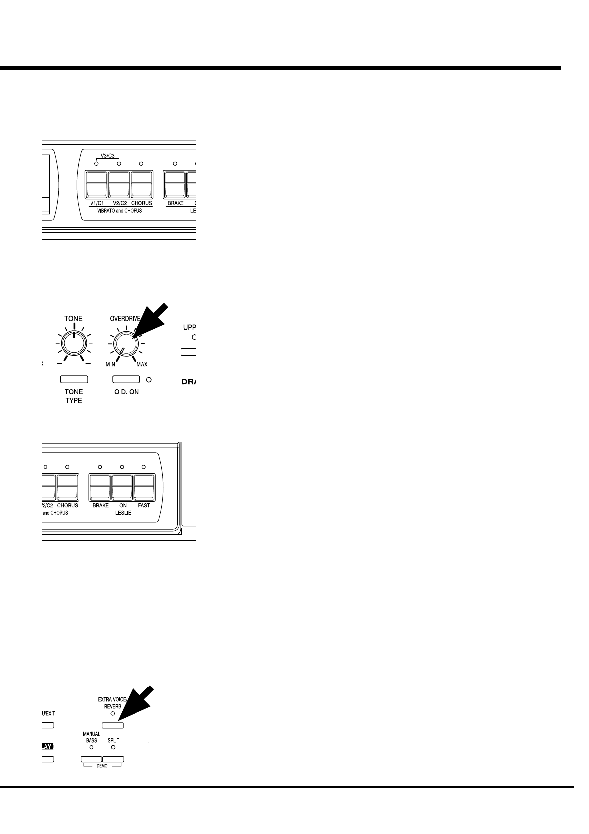
VIBRATO/CHORUS
OVERDRIVE
“Vibrato and Chorus” slightly changes the Drawbar pitch at a certain ratio and add warmth to
the sound.
[V1/C1], [V2/C2] Button
Controls the Vibrato Depth and Switches on and off the Vibrato effect. The LED turns on
when it is ON.
The Vibrato effect is OFF when the two LEDs are OFF and are at maximum Vibrato Depth
when the two LEDs are ON (V3).
[CHORUS] Button
It mixes Vibrato and original sound (= Chorus Effect) and adds richness to the sound.
NOTE: You can set the speed of Vibrato/Chorus. (P. 69)
The overdrive effect simulates the effect of applying an excessively high signal to the
amplifier input which causes distortion of the sound.
[O.D. ON] Button
Press this button to switch on the LED, and get the Overdrive Effect.
[OVERDRIVE] Knob
This knob controls the degree of distortion. The Overdrive effect is minimum when the knob
is turned fully counter clockwise “MIN”. The Overdrive effect gets maximum when it turned
to “MAX” clockwise.
LESLIE
The bass rotor and the rotating horns produce the effect of the spatial, dynamic and lively
theater stage performance.
[LESLIE ON] Button
Touch “ON” to switch on, the LED is lit.
[LESLIE FAST] Button
This button controls the two rotor speeds. When the LED is ON, it is FAST. When the LED is
OFF, it is SLOW. The most effective and popular way to use this is to mainly play SLOW
and lead to the climax by changing to FAST.
[LESLIE BRAKE] Button
This is to set the action when the LESLIE ON Button is OFF.
When the LED is ON, BRAKE is on. The rotation gradually slows down and stops finally).
When the light is OFF, it is THROUGH. The Leslie effect is by-passed.
NOTE: You can control the rotors by these buttons when you connect the LESLIE to
NOTE: You can finely adjust the rotation speed etc. of the internal LESLIE Effect. (P.
USING EXTRA VOICES
You can use Extra Voices (i.e. Electric Piano, Clav, etc.) instead of organ sounds.
the external equipment.
66)
[EXTRA VOICE / REVERB] Button
To use the Extra Voice, touch the button and switch on the LED.
NOTE: You can select the Extra Voice. (P. 74)
Turn On and Play
Page 26
26
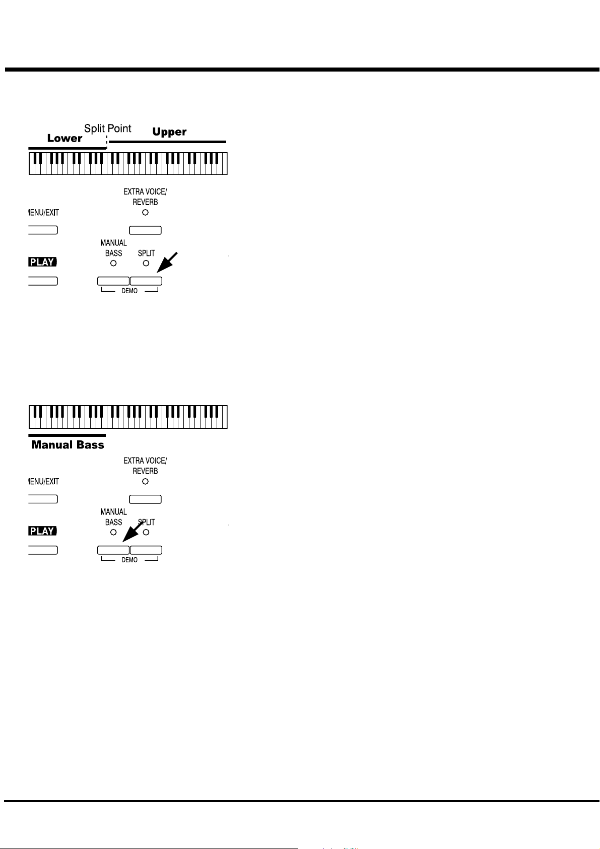
Divide the keyboard into two parts - left and right. [SPLIT]
This keyboard has only a single manual. But you can change the setting and play it
as it was a double keyboard organ, using this “SPLIT” function.
[SPLIT] Button
Switch on the LED by pressing the button, to “split” the manual.
The factory “SPLIT” setting is to divide it between B2 and C3 in the center.
NOTE: Split Point or Octave can be moved. (P. 82)
NOTE: The Split function does not work, when the MIDI IN jack is used for
“LOWER/PEDAL”. (P. 84)
The right-hand side of the split point is called UPPER to make sound by the
Drawbars (switch Drawbar Select [UPPER]) and Percussion. The left-hand side is
called LOWER and makes sound with the Drawbars (switch Drawbar Select
[LOWER]). Percussion does not sound with LOWER.
Add bass part on the manual keyboard. [MANUAL BASS]
You can play the Bass using the lowest keys.
This is called “Manual Bass”.
[MANUAL BASS] Button
To use the Manual Bass function, press the button and switch on the LED.
Not to interfere with the Melody performance, this function is limited only upto
B2 in the center when it leaves the factory.
NOTE: You can move the upper limit of the Manual Bass. (P. 82)
NOTE: The Manual Bass function is controlled by connected MIDI keyboard
when the purpose of the MIDI IN jack is at “LOWER/PEDAL”. (P. 84)
The bass part obtained by the Manual Bass is called the PEDAL, and makes sound
controlled by the Drawbars (switch Drawbar Select [PEDAL]). This is designed
so that the Bass is played by the pedal keyboard as on the three-keyboard organ.
NOTE: You can choose sounding polyphonic (POLY) or lowest note
(MONO). (P. 55)
You can use both the Manual Bass and the Split at the same time. So, you will be
able to play Bass, Chord and Melody all by yourself.
What is “Part”?
A “PART” plays like a “musician” in a band or an orchestra does.
Like the three-keyboard organs, this keyboard has three parts, UPPER, LOWER and PEDAL, and
so you can play three different parts.
This keyboard has only a single manual, but it is possible to play plural parts, using the SPLIT
and/or using MIDI keyboards to expand the keyboard.
NOTE: The function for plural tones is called “Multi-timbre”.
*#1 :-Owner’s Manual
Page 27
STORING REGISTRATIONS IN COMBINATION PRESET
All the afore-mentioned settings can be memorized to the Combination
Preset.
The data stored at the factory can also be freely re-written.
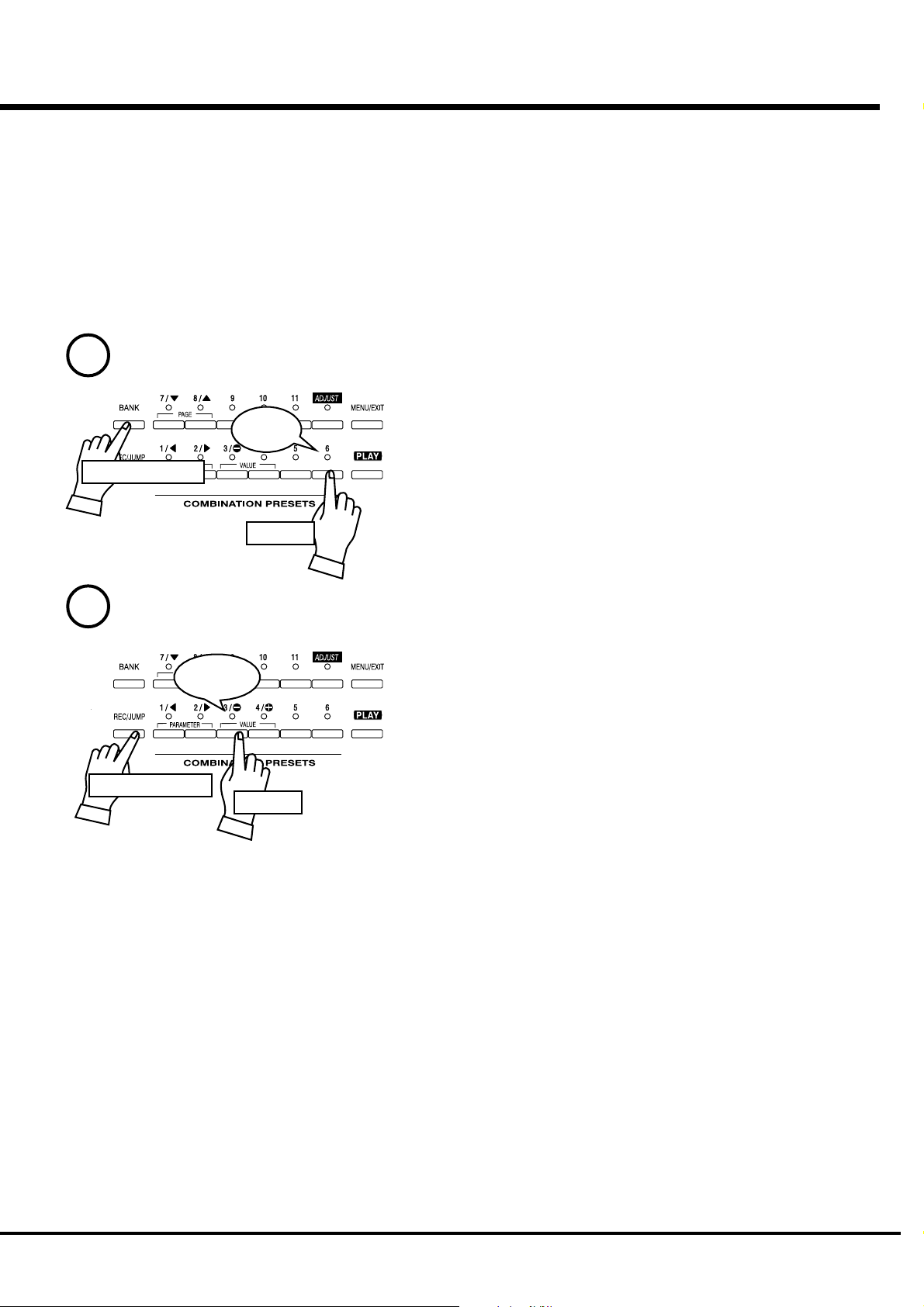
EX. Memorize to “6 - 3”.
27
1
Press and Hold
2
Press and Hold
Flash to
On
Light
Touch
Touch
1. While pressing the [BANK] Button, touch the Preset Button [6].
This turn on Preset BANK 6. The LED on the Preset Button indicates BANK
while the [BANK] Button is pressed.
NOTE: The LED goes out if you release the button. This means the
Preset NUMBER is not decided.
-Now that we are in Bank 6. Let’s record Number 3.
2. While pressing the [REC/JUMP] Button, touch the Preset Button [3].
The Preset is stored and Recording Preset appears on the display for a while.
When the recording is completed, the LED on the Preset Button [3] flashes for
a few seconds and then stays on. The Display returns to the previous mode.
The recorded Preset will be automatically selected.
The Preset Button [ADJUST] can not memorize registrations by this
operation.
NOTE: The recorded Preset data is retained in memory if the power is
switched off.
NOTE: See the “Preset Parameters” in Appendix section for detail of the
parameters will be saved.
Turn On and Play
Page 28

28
*#1 :-Owner’s Manual
Page 29

SETTING UP
29
*#1 :-Owner’s Manual
Page 30
30
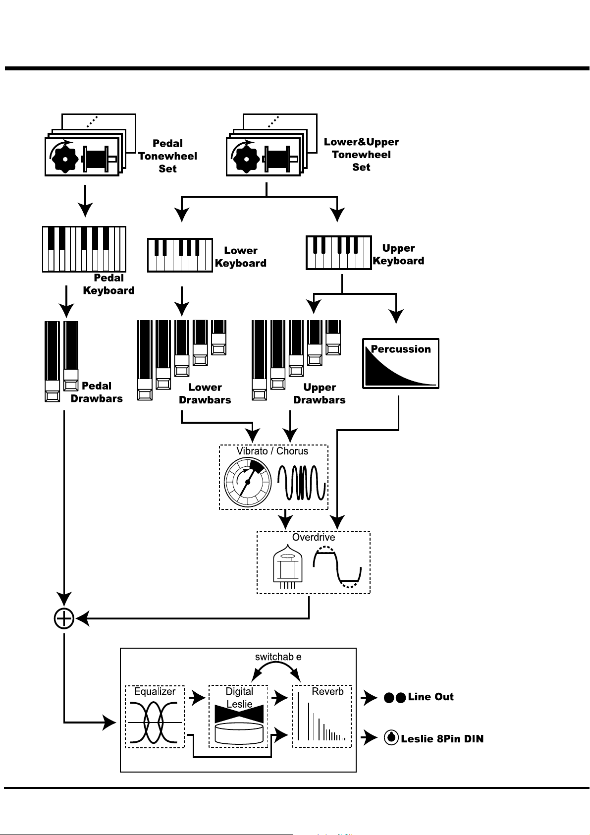
SOUND ENGINE STRUCTURE
SYSTEM STRUCTURE OF XK-1 KEYBOARD
*#1 :-Owner’s Manual
Page 31
To fully enjoy playing this keyboard, please read the following section
of this manual.
See the illustrated System Structure of your keyboard on the left page.
31
TONE-WHEELS
The sound source or “engine” of Hammond Organ is the Tone-wheels. They are
like the strings and pick-ups on the electric guitar. While running, each of the 96
digital Tone-wheels keeps oscillating at a different pitch/frequency.
KEYS
Each of the sound signals made by the 96 ditgital Tone-wheels is switched at
each key. Each signal corresponding with each pitch and harmonic is distributed
to each key (as an example, 9 signals for the manual keyboard). The keys are
switched on and off by depressing and releasing the keys.
DRAWBARS
The Draw-bars prepare the basic sounds. Each bar adjusts the value of a
harmonic (as an example, 9 harmonics for the manual keyboard).
PERCUSSION
The Percussion makes decay sound, synchronizing with the key touch of the
UPPER part.
VIBRATO/CHORUS
Vibrato gives vibration to the pitch. By mixing the vibrato sound with the
fundamental sound, Chorus effect is obtained.
NOTE: On this keyboard the scanner circuit of the B-3/C-3 is simulated, which
gives more effects than the changes of the pitch.
TONE-WHEEL SET
The Tone-wheel Sets are divided into the
Manual Keyboard and the Pedal Part. This is
to give the Pedal Part the Decay (= the sound
gradually fading out while pressing the key)
or Sustain Effect. (= the sound gradually
fading out after the key is released).
HARMONICS
Harmonic is a pitch of a different ratio to a
certain pitch; for example, the one octave
higher C to the middle C. The more Harmon-
ics, the brighter and richer the sound.
OVERDRIVE
Overdrive adds the fuzzy, raspy, “dirty” sound created by the vacuum tubes of a
tube-style Leslie Speaker when its volume is pushed past its sound limit.
The PEDAL Part, however, is designed not to pass through the Vibrato/Chorus
or the Overdrive, in order to obtain the clear Bass-line.
EQUALIZER, LESLIE and REVERB
The sound comes out of the output terminal, after passing the spatial effects: the
Equalizer (for tone regulation), the Leslie (for the rotating speaker effects) and
the Reverb (for resonance). (The built-in Leslie Effect does not work at the
Leslie 8-pin terminal.
NOTE: The built-in Leslie Effect is designed to smoothly simulate the rotations of
the two rotors.
Setting Up
Page 32

32
DRAWBARS™
The 9 Drawbars on this keyboard are used to make the basic sounds. Each Drawbar is marked
with the numbers 1 - 8. If you push back the Drawbar until you can not see any number at all,
the sound of the Drawbar is not heard. If you pull it out to the fullest position THE SOUND
LEVEL is maximum.
Except when the Preset Button is [ADJUST], the actual Drawbar Registration is the value
displayed in the (display-)window. The “Drawbar Registraion” shows the length of the
pulled-out Drawbar(s). The display shows only the Drawbar(s) you operate.
The pitch of each Drawbar is as shown above, when the middle C is depressed. The footage
marked (') on each Drawbar is originated from the length of the pipes of the pipe organ.
The numbers 1 - 8 on each Drawbar indicate the volume of the sound to be produced as well
as the guide to simply set the Drawbar.
For example, when you blow clarinet, the internal air vibrates, and the fundamental (8') and
the third harmonic (2 2/3') plus the fifth harmonic (1 3/5') come out at the same time. On this
keyboard, if you pull out 3 Drawbars, you can get the clarinet sound. If you pull out the right
hand side one of the 3 Drawbars a little longer and the left hand side one a little shorter, the
element/component of the high pitch increases and a hard sound comes out. If you pull out the
left hand one a little longer, on the contrary, the sound gets mellow.
Thus, you can make delicate changes to the sound, depending on the flow of the tune/music
or your choice/preference, by fully utilizing the Drawbars.
NOTE: You can change the characters of the Drawbars. (P. 54)
*#1 :-Owner’s Manual
Page 33

WHITE DRAWBARS
BLACK DRAWBARS
33
In each Drawbar set, the white Drawbar (8') on the left end makes the
basic/fundamental sound. The other white Drawbars get higher by the
octave to the right.
The sounds of the black Drawbars, too, play important roles in building
rich tones. Their pitches are fifth and third to the fundamental. They
contain the elements of all different harmonics of such as the sweet and
soft horn, mellow strings and so on.
BROWN DRAWBARS
PEDAL DRAWBARS
The two brown Drawbars on the far left have the role to give depth and
richness to the sound. The left 16' is one (1) octave lower than the 8,' and
5 1/3' is the third harmonic of the 16' fundamental.
Normally, the tones are built on the 8' fundamental, but, if you want to add
depth to the tone or to expand the playing range on the manual by one (1)
octave, the tones are built on the 16' fundamental.
The Pedal Part for playing the bass line usually, using the only two
Drawbars -16' and 8'. Others are not use.
The first Pedal Drawbar produces a tone at 16' pitch for a deep foundation
bass, while the second Pedal Drawbar produces a tone at 8' pitch, or one
octave higher.
The registration of the Pedal Part is displayed on the center of the display,
left one is 16', and the right one is 8'.
Setting Up
Page 34

34
DRAWBAR REGISTRATION PATTERNS
The Drawbar Registration is matched by the number value of each Drawbar as shown below on right
side of Drawbar settings name. However, it is rather reasonable to remember the typical combinations
of the 9 Drawbars by their forms/shapes.
Flute family (2 step pattern)
Accompaniment Flute 8' I
Accompaniment Flute 8' II
Accompaniment Flute 8' III
Chorus of Flutes 16'
Orchestral Flute 8'
Piccolo 2'
Stopped Flute 8'
Tibia 8'
Tibia 4'
Tibia (Theater) 16'
Wooden Open Flute 8'
00 8460 000
00 3220 000
00 8600 000
80 8605 002
00 3831 000
00 0006 003
00 5020 000
00 7030 000
00 0700 030
80 8605 004
00 8840 000
Reed family (triangle pattern)
Bassoon 16'
Clarinet 8'
English Horn 8'
Flugel Horn 8'
French Horn
Kinura 8'
Oboe 8'
Trombone 8'
Trumpet 8'
Tuba Sonora 8'
Vox Humana 8'
44 7000 000
00 6070 540
00 3682 210
00 5777 530
00 7654 321
00 0172 786
00 4764 210
01 8777 530
00 6788 650
02 7788 640
00 4720 123
*#1 :-Owner’s Manual
Page 35

Diapason family (check mark pattern)
Accomp. Diapason 8'
Chorus Diapason 8'
Diapason 8'
Echo Diapason 8'
Harmonic Diapason 16'
Harmonic Diapason 8'
Harmonic Diapason 4'
Horn Diapason 8'
Open Diapason 8'
Solo Diapason
Wood Diapason 8'
35
00 8874 210
00 8686 310
00 7785 321
00 4434 210
85 8524 100
00 8877 760
00 0606 045
00 8887 480
01 8866 430
01 8855 331
00 7754 321
String family (bow pattern)
Cello 8'
Dulciana 8'
Gamba 8' I
Gemshorn 8'
Orchestral String 8'
Salicional 8'
Solo Viola 8'
Solo Violin 8'
Viola da Gamba 8'
Violina 4'
Violone 16
00 3564 534
00 7770 000
00 3484 443
00 4741 321
00 1464 321
00 2453 321
00 2474 341
00 3654 324
00 2465 432
00 0103 064
26 3431 000
Setting Up
Page 36

36
DRAWBAR SELECT
ASSIGN THE DRAWBARS FOR EACH PART
Touch
On this keyboard, there are 3 Parts: UPPER, LOWER and
PEDAL, and each of them has the corresponding Drawbars.
The manual on the keyboard is usually assigned to the UPPER
position. If you want to play the LOWER or PEDAL Part, use
the Split or Manual Bass functions, or connect a MIDI key-
board and assign each part.
Touch again
The Drawbar Select Button can be turned off by re-touching,
and the no works to tell the controlling Drawbars. This means
that you can make the new resistration while playing and
There is one set of Drawbars on this keyboard, though this
keyboard has 3 Parts. Use Drawbar Select Buttons for assign-
ment of the Drawbars for each of the Parts.
The Drawbar Select Buttons [UPPER], [PEDAL], [LOWER]
are used for selecting “which Part the Drawbars will be
assigned to”.
change it.
To match the registration, use the function below.
MATCH THE REGISTRATION TO DRAWBARS
If you recall the Combination Preset, the Drawbar Registration
is not physical but is replaced with the recorded/memorized
one. If you move any Drawbar at this stage, only the Footage
moved is changed.
To match only the Registration to the Drawbars while using the
Press and
Hold
*#1 :-Owner’s Manual
content of the Combination Preset, keep depressing the Preset
Key for a while. The Combination Preset is recalled and then
the physical Drawbar Registration is reflected.
Release
Page 37

PERCUSSION
The Percussion attack sound is a Hammond exclusive.
Percussion is usually used with the Drawbar sound.
[SECOND] BUTTON
The second harmonic, or 4' Drawbar decay, is added to the UPPER Part.
To use this, press the [SECOND] button , and the LED will light.
[THIRD] BUTTON
The third harmonic, or 2 2/3' Drawbar decay, is added to the UPPER Part. By mixing it
with the Drawbars, a distinotive sound is obtained.
To use this, press the [THIRD] button , and the LED will light.
37
DECAY
The piano sound gradually goes out even
if you keep the key down. This is called
“decay”. The violin, on the contrary,
keeps sounding at a certain volume. This
is called “sustain”.
[FAST] BUTTON
This provides a short decay time for Percussion.
It is effective if you use this to play with a clear-cut rhythm in an up-tempo piece.
When the LED is OFF, it is SLOW. It goes “FAST” when you press the [FAST] button ,
and the LED will light.
[SOFT] BUTTON
This reduces the volume of Percussion.
When the LED is OFF, it is NORMAL. If you press the [SOFT] button, the percussion
level is soft, and the LED will light.
NOTE: You can fine-adjust Percussion. (P. 65)
NOTES
“Percussion does not sound!”
The factory default setting: Percussion does not produce sound except at the Preset
Key [ADJUST], if the Combination Preset is Bank 12. (See left.) This setting is the
same as on the B-3/C-3.
NOTE: You can set any Preset Key to sound Percussion. (P. 56)
DRAWBAR CANCEL
When either the [SECOND] or the [THIRD] button is ON, 1' in the Upper Part Draw-
bars does not produce sound. This is the same action as on the B-3/C-3.
NOTE: You can set to play 1' Drawbar, while Percussion is ON. (P. 65)
Setting Up
Page 38

38
VIBRATO/CHORUS
VIBRATO adds warmth to the tone, by slightly changing the Drawbar pitch at a
certain speed.
You can also add richness to the sound by mixing the Vibrato sound with the
fundamental (= Chorus Effect).
[V1/C1], [V2/C2] BUTTON
This switches ON/OFF Vibrato/Chorus Effects and sets the its depth.
It affects on the UPPER and LOWER Part.
To get this effect, touch the button and the LED will light.
V-1: Comparatively slight Vibrato (on only [V1/C1])
V-2: Standard depth Vibrato (on only [V2/C2]]
V-3: Deepest Vibrato (on both [V1/C1] and [V2/C2])
[CHORUS] BUTTON
This switchs Vibrato or Chorus Effects.
To get the Chorus Effect, touch the button and the LED will light.
NOTE: You can change the speed of the Vibrato Effect. (P. 69)
BUTTONS AND STATUS
Button
V1/C1 V2/C2 CHORUS Effect
Off Off Off
Off Off On
On Off Off
Off On Off
On On Off
On Off On
Off On On
On On On
State
Through
V-1
V-2
V-3
C-1
C-2
C-3
*#1 :-Owner’s Manual
Page 39

OVERDRIVE
The Overdrive produces the distorted sound like that of an over-driven amplifier.
By changing the amount of the Drive, various Tube Sounds are obtained, from the
unclipped clean to the hard-distorted fuzzy, raspy Overdrive sound.
39
[O.D. ON] BUTTON
This button switches on/off the Overdrive Effect.
Press this button to switch on the LED, and get the Overdrive Effct.
[OVERDRIVE] KNOB
This is for adjusting the distortion value of the Overdrive Effect.
It does not clip, if turned to the left all the way (by-passed the effects).
As you turn it to the right, the distortion value increases.
NOTE: You can fine-set the distortion degree. (P. 69)
Setting Up
Page 40

40
LESLIE
LESLIE EFFECT is the simulated sound of rotating speakers.
If you connect the real Leslie speakers to this keyboard, it controls those (speakers)
[ON] BUTTON
If you touch this button, the LED will light, and the rotor starts turning. Also the
voice is heard thru the rotary channel.
[FAST] BUTTON
This switches the speed of the rotor in two steps. It switches every time you touch
it. When the LED is ON, it is FAST, and when the LED is off, it is SLOW.
[BRAKE] BUTTON
This button sets the action when the [ON] button is OFF.
When the LED is ON, it is in BRAKE mode (= The speed gradually slows down
and stops.) and if the LED is OFF, it is THROUGH. (= The Leslie effect is by-
passed and the voice comes out of the stationary channel.)
NOTE: You can not to control the Break or Through on external Leslie Speakers.
NOTE: You can fine-set the LESLIE effect i.e. speeds. (P. 66)
In the Leslie speakers, generally, an amplifier and two rotors are
incorporated, i.e. the “Horn Rotor” responsible for the treble and
the “Bass Rotor” for the bass.
Each rotor has a speaker or speakers and a motor for controlling
speed to give the unique tremolo sound gained by the Doppler
effect.
There are also models as have not only the rotors but stationary
speakers - switchable.
The circuit to send the sound to the rotor is called “Rotary
Channel” and that to the stationary speaker is called “Stationary
Channel”.
The built-in Leslie Effect simulates them and you can get the best
effect when connected stereophonic.
BUTTONS AND LESLIE STATES
Button
BRAKE ON FAST
On On On
Off On On
On On Off
Off On Off
On Off On
On Off Off
Off Off On
Off Off Off
WHAT IS THE LESLIE EFFECT?
State
External
Leslie
Speaker
Fast Through
Slow Through
Internal
Leslie Effect
Fast
Slow
Brake
*#1 :-Owner’s Manual
Page 41

The Equalizer and the Reverb effects give the final touch to the tone.
The Equalizer regulates the tone, and the Reverb adds the resonance of the hall
performance.
You can control these functions with the panel buttons and knobs
EQUALIZER
EQUALIZER & REVERB
[TONE] KNOB
Can be setup to control any one of the three tone types.
When delivered from the factory, TREBLE is assigned, and, as you turn it to the right,
the treble is emphasized, and, to the left, the trebel is reduced.
[TONE TYPE] BUTTON
This assigns the settings to the [TONE] KNOB.
At every touch, the assignment changes in the order of TREBLE, BASS and
MIDDLE. The initial letter of the word is displayed in the PLAY mode.
NOTE: For further details, please read the section “EQUALIZER” (P. 70)
41
REVERB
The illustration indicates
TREBLE is at +9.
[EXTRA VOICE / REVERB] BUTTON
This is for switching ON and OFF the Reverb Effect when the assignment for this
button is REVERB (P. 61).
NOTE: You can change the time and the depth of the Reverb. (P. 71)
Setting Up
Page 42

42
The settings you have made can be recorded into the Combination Presets.
BANK AND NUMBER
Combination Presets
Number
1 2 3 4 567 8 9 10 11 Ad
1
2
3
4
5
Bank
6
7
8
9
10
11
12
COMBINATION PRESETS
The combination preset chart to the left, shows the [BANK]
and the [NUMBER], information.
Access is made by the Preset Buttons. To select the [BANK],
press the key, holding down the [BANK] button. To select the
[NUMBER], just press the Preset Button.
Adjust
Recording and recall is determined when the Number is
designated. Only selecting the Bank does not affect the
recording or recall.
Refer to the illustration on the left bottom for each Button and
Name.
The [ADJUST] button on the right end is a special Preset,
called “Adjust Preset”. Here the Drawbar Registration on the
panel always matches the internal registration.
NOTE: The setting of the Preset Buttons [C] to [A] on the B-3/C-
3 is fixed, and the [A#] and [B] are used to switch the
Drawbar Registration on the panel. However, on this
model, you can change the setting by moving the
Drawbars, even while using the buttons [1] to [11].
COMBINATION PRESETS
On the original B-3 organ, the preset keys only stored drawbar
registration information. On the XK-1 however, in addition to
drawbar registration, you can store many various parameters to a
preset. Thus the name “Combination Preset”.
NOTE: The parameters to be recalled by the Preset Keys can be
limited Bank by Bank. (P. 56)
*#1 :-Owner’s Manual
Page 43

NAME THE COMBINATION PRESETS
Go to the MENU.
1
Touch the [MENU/EXIT] button.
The MENU mode will be displayed.
Go to PAGE A.
2
If the PAGE A is not displayed, touch the [PAGE] button and
go to PAGE A.
43
Go to the PRESET FUNCTION mode.
3
Input THE NAME.
4
Touch the [2] PRESET button and go to the PRESET FUNC-
TION mode.
You can store names up to 10 letters.
[PARAMETER] Button: moves the cursor.
[VALUE] Button: selects letters.
You can use all the Alphabet letters large and small, signs/
symbols and digits.
To jump to the beginning of each list, hold down the [REC/
JUMP] button, and touch the [VALUE] button. You can select
letters etc. by the [VALUE] knob, as well.
The name put here is only temporary. Do the recording
operation to save it, as explained on the next page.
Setting Up
Page 44

44
RECORD A NEW THE COMBINATION PRESET
EXAMPLE: Record into “6-3”.
Go to the PLAY mode.
1
If the display is not in PLAY mode, touch the [PLAY] button to
back to the PLAY mode.
This operation is not necessary, if the display is in PLAY mode.
Select the Bank.
2
Select the Number.
2
Press and hold
Press and hold
Flash to
On
Touch
Lights
Touch
While holding down the [BANK] button, touch the Preset
Button [6].
The LED on the Preset Key indicates the BANK while you are
holding down the [BANK] button.
NOTE: The LED will be OFF, if you release the button. This
means the Preset is not stored.
This operation is not necessary, if you do not change the Bank.
Press the Preset Button [3], while holding down the [REC/
JUMP]. The Preset becomes final and the display shows as
follows for a few seconds.
Recording Preset...
When the recording is completed, the LED on the Preset Button
[D] flashes for a while. (The recorded Preset Number will be
automatically selected.)
The display will return to the previous screen.
You can not record to the Preset Button [ADJUST] by
using this procedure.
NOTE: The Preset data recorded will not be lost even after you
switch off the power.
*#1 :-Owner’s Manual
Page 45

USING THE
45
CONTROL PANEL
*#1 :-Owner’s Manual
Page 46

46
OPERATION CONTROL PANEL
You now know you can control many settings by using the buttons and
knobs on your keyboard. You can do even finer settings like the delicate
speed of the Leslie Effect or the MIDI equipment, using the display buttons
on the Control Panel.
There are PLAY, MENU and FUNCTION modes in the display.
The buttons and knobs in each mode is explained on the following pages.
PLAY mode
MENU mode
FUNCTION mode
*#1 :-Owner’s Manual
Page 47

PLAY MODE
The PLAY MODE is the basic display for all the operations. The necessary infor-
mations for the normal play will be displayed.
There are two types of PLAY MODE screens to display the Drawbar Registration.
One is by showing the length of the Drawbars and the other by digits.
How to show this display:
1. Immediately after powered ON and the start up process is complete, the PLAY mode is
displayed.
2. If a different mode is displayed, touch the [PLAY] button.
HOW TO READ THE DISPLAY
Drawbar registration
UPPER Part/ PEDAL Part/ LOWER Part
47
BAR display
DIGITAL display
Number on UPPER Part/
Number on LOWER Part
Preset Bank -
Number :
Name
Preset Bank -
[TONE] knob
Assignment:
Value
Value of
OVERDRIVE
These two PLAY mode displays (= the bar
display and the digital display) will be switched
every time you touch the [PLAY] button.
In the bar display, the Combination Preset name
is shown but another Preset Key, if assigned to
the LOWER Part is not shown.
Also, the function assigned to the [TONE] knob
and its value is displayed.
The Preset name is not shown in the digital
mode display, but you can see the Preset
Number of the LOWER Part.
Also, the value of the Overdrive and the MIDI
IN Note Information is displayed.
Sounding on MIDI Note
Message
Using the Control Panel
Page 48

48
The MENU mode is the path for each function.
MENU MODE
How to show this display:
Touch the [MENU] button.
There are several pages which contains many various FUNCTION displays. Move
from page to page and find the item where you want to go and touch the numbered
button to see the desired display.
HOW TO READ THE DISPLAY
FUNCTION ITEM
(If none, blank.)
PAGE
BUTTON OPERATION IN THIS MENU
Moves from a page to another.
You can jump to the top or bottom page
by touching these buttons with holding
down the [REC/JUMP] Button.
These are for entering each FUNCTION
MODE corresponding with the item
displayed.
*#1 :-Owner’s Manual
Returns to the PLAY mode.
Page 49

FUNCTION MODE
The FUNCTION MODE is for making each setting and adjustment.
There are many displays, but the basic operation is the same.
HOW TO READ THE DISPLAY
This shows there are PAGEs
above (or below).
PAGE
NAME
VALUE CURSOR
PARAMETER
(Flashing VALUE)
49
This shows there is a PAGE on the
right (or on the left).
CURSOR
In the display window of this keyboard,
the CURSOR is displayed in the flashing
style, while the most popular indicator-
cursor used on the PC, the mobo, etc. is
in the shape of an arrow, a square or an I-
shape.
BUTTON OPERATION IN THIS MODE
Moves from a page to another.
You can jump to the top or bottom page by touching these
buttons with holding down the [REC/JUMP] Button.
This button is used to move the CURSOR
right or left for selecting the PARAMETER to
change.
The CURSOR moves to the edge of the
display and on to the next page (on the right
or left), if there is one.
Touching this button while holding [REC/
JUMP] button, you can move to the right or
left page regardless where the cursor is.
Returns to the
PLAY mode.
The CURSOR increases or decreases
the value of the Parameter.
Holding it increases (or decreases) the
value continuously.
Touching it while holding the [REC/
JUMP] button increases (or decreases)
the value quickly.
The value can also be changed by the
[VALUE] knob on the left.
Using the Control Panel
Page 50

50
Example of operation:
Adjusting the DECAY TIME of the Percussion [FAST]
1
Go to the MENU Mode.
Touch the [MENU] button.
The [MENU] mode is displayed.
2
Select the PAGE.
Search for the PERCUS page, using the
[PAGE] button.
“PERCUS” is on PAGE B. So select PAGE
[B].
Touch the Number button.
3
Move the CURSOR to the Parameter you want to change.
4
Touch the [4] button for “PERCUS”.
Now you are on the (first page) of the
Percussion Function display.
DECAY TIME is on the “DECAY” PAGE.
Move to that page using the [PAGE] button.
“FAST” is on the right end. Move the
CURSOR (flashing value) to underneath
“FAST” using the [PARAMETER] button.
*#1 :-Owner’s Manual
Page 51

Change the value.
5
Back to PLAY mode.
6
51
Decrease the value, using the [VALUE]
button or the [VALUE] knob on the left.
NOTE: Repeat the operation 1 - 5, if you want
to change other parameters, too.
Touch the [PLAY] button to return to the
PLAY mode.
Record a new Combination Preset.
7
The “DECAY FAST” is a Preset Parameter. It will go back to the set value if you
call out the other (or current) Combination Preset.
If you want to continue to use the changed value hereafter, you must record the
value into the Combination Preset.
Touch and Hold
PRESET PARAMETERS
They are the Parameters to be recorded
into each Combination Preset.
They include the Parameters for setting
the status of the buttons/knobs on the
panel, “Decay Fast” and many others.
The overall/general common Parameters
(which are not included in the Combina-
tion Presets) are called “Global Param-
eters.”
Touch
Using the Control Panel
Page 52

52
Each button on the panel has a “SHORT-CUT” capability, so that you can easily
go to each Function mode. By holding down the button, you can easily go to the
desired mode display. The “SHORT-CUT” mode can save time by going directry
to the parmeters you want to change.
SHORT CUT TO THE FUNCTION MODE
Example of operation: Move to the Percussion Function Mode.
For example, if you want change the Percussion setting, you can go
to the PERCUSSION FUNCTION MODE display, by holding
down either [SECOND], [THIRD], [FAST], or [SOFT] for a few
Touch and Hold
seconds. This enables the “SHORT CUT” mode.
Short-cut buttons will be explained in the next Chapter “SETTING
THE PARAMETER”.
NOTE: You can change the time for holding down the button for “SHORT
CUT”. (P. 61)
STORING THE PAGE YOU FREQUENTLY USE
You can store the page which your usually use, and go to that page by only touch-
ing the [CONTROL] button.
Example of operation: Storing the Drawbar - Pedal Function
1
2
Touch with
Press and
Hold
Go to the page to be stored by using MENU etc.
Touch and hold the [REC/JUMP] , and touch the [CON-
TROL] button.
Next time, you can come to this page by only touching the
[CONTROL] button.
*#1 :-Owner’s Manual
Page 53

SETTING THE
53
PARAMETERS
*#1 :-Owner’s Manual
Page 54

54
DRAWBAR
In this mode, you can set the Parameter relating to the Drawbar sound of each part.
To locate the Drawbar mode:
Touch the [MENU/EXIT] button and display MENU, touch the [PAGE] button and select
PAGE A and choose [1] DRAWBAR.
9
10 11
131514
12
2 4 5 6
1
3
Setting the Manual (LOWER and UPPER)
1. TONE-WHEEL
Select the TONE-WHEEL SET (waveform) for the manual part.
B-type: The traditional Tonewheel Sound of B-3/C-3
Mellow: Sine wave
Brite: The analog sound represented by X-5
2. CLICK - ATTACK LEVEL
This allows you to set the Key-Click VOLUME of the ATTACK (= when you touch
the key). The larger the value, the louder it gets. No key-click at 0.
NOTE: When this parameter is changed, also 4. Envelope - Attack Rate will be changed
to its suitable value automatically.
3. CLICK - LPF
This allows you to set the tone of the Key-Click.
The setting range is 0 - 127. The larger the value, the brighter it gets.
7 8
TONE-WHEEL SET
Each Tone-wheel Set allows you to make finer
adjustment. (P. 64)
KEY-CLICK
The "Key Click" is the noise heard every time the key
is touched or released on the B-3/C-3, as the voice is
generated by mechanically switching ON and OFF on
these models. The function on this model simulates
the good old noise.
4. ENVELOPE - ATTACK RATE
This allows you to set the speed of the Drawbar at Attack (when you touch the key).
The more the value, the slower it gets. The volume will be maximum(= loudest) at 0 at
the time you touch the key.
5. CLICK - RELEASE LEVEL
This allows you to set the volume of the Key-Click at RELEASE (= when you release
the key). The larger the value, the louder it gets. No Key-Click at 0.
NOTE: When this parameter is changed, also 6. Envelope - Release Rate will be changed
to its suitable value automatically.
6. ENVELOPE - RELEASE RATE
This allows you to set the Decaying Speed of the Drawbar Sound at Release (when
you release the key). The higher the value, the slower the RELEASE gets. The sound
dies at 0 at the same time as you release the key.
7. FOLD-BACK - LOW
This allows you to set at which key the 16' Drawbar starts the FOLD-BACK. (Fold-
back: Repeating the same octave in a certain range on the keyboard.)
The first key (= the far left key on the manual, next to the Preset Keys) is displayed as
"1C". The setting range is 1C - 2C.
*#1 :-Owner’s Manual
FOLD-BACK
As the number of the tonewheels was limited on the
B-3/C-3, the organs were designed to repeat the
same octave in the upper-most or lower-most range.
The feature of this model is to simulate that.
Page 55

8. FOLD-BACK - HIGH
This allows you to set which key the 1' Drawbar starts to FOLD-BACK (= repeat the
same octave) in the upper-most range. The set range is 4G - 5C.
NOTE: The FOLD-BACK can be set not only on the 1' but also 1 1/3', 1 3/5', 2' and 2 2/3'
Drawbars.
Setting the PEDAL
9. TONE-WHEELS
This allows you to select the Tone-wheel waveform of the PEDAL.
Normal: The traditional B-3/C-3 Tone-wheel sound
Muted: Analog sound represented by the X-5.
Synth1: Sawtooth waveform with swept filter.
Synth2: Dull square waveform.
NOTE: You can come to this page by holding down the [MANUAL BASS] Button as well.
10. ATTACK
This allows you to set the Attack Rate and the Key-Click Volume at ATTACK and
RELEASE.
MAX CLK: Immediately attacks and the key-click is loud.
NORM CLK: Immediately attacks and the key-click is normal.
SOFT CLK: Immediately attacks and the key-click is soft.
NO CLK: A slightly slower attacks without key-click
SLOW ATK: Slow attack without key-click
55
11. DECAY RATE
This allows you to determine whether to keep voicing or to decay, or set the decay
time, while holding down the key.
The setting range is 1 - 5 and C. The longer the value gets, the longer gets the decay
time. No decay at C.
12. SUSTAIN - ON
This allows you to set whether or not to use the Sustain function.
13. SUSTAIN - LENGTH
This allows you to set the Release Rate (= the decay time after you release the key),
when the SUSTAIN - ON (item #12) is ON.
1 is the shortest. And 5 is the longest.
14. VELOCITY
This allows you to set the response to the Velocity. The setting range is OF and 1 - 4.
At OF, the volume does not change however hard you touch the key. As the value
increases from 1 - 4, the sound gets louder even if you touch the key softly.
15. KEY MODE
This allows you to set the Pedal polyphony.
POLY: Makes it possible to play chords (up to 3 notes)
MONO: Only the lowest note will sound, when you play a chord.
NOTE: The previously relased note will be cut when you touch the new one, even when
the PEDAL is in the POLY mode and SUSTAIN is ON.
NOTE: When the note-data of the Pedal are received from the MIDI IN terminal while the
value of the parameter [MIDI IN] (P. 84 #2) is “IN1/IN2”, the Pedal produces
polyphonic sound, regardless of the value.
SUSTAIN
This is the function that the volume slowly fades out
after the key is released, not like that of the
synthesizers.
VELOCITY
“Velocity” is the speed a key is depressed.
When you touch the piano hard, the hammer hits the
string hard and so the sound is loud.
The organ key is, on the other hand, generally only
the switch to open the valve, and so the sound does
not change however hard you may touch the key.
So this function is effective if you use when the
Decay Rate is other than C, or Decay.
NOTE: All the parameters in these modes are Preset Parameters. They are recorded into
the Combination Preset.
Setting the Parameters
Page 56

56
PRESET
In this mode, you can name the Combination Presets.
To locate this mode:
Touch the [MENU/EXIT] button and display MENU, then touch the [PAGE] button to
select PAGE A and touch the [2] PRESET button.
2 3
1
PRESET NAME
1. Preset Name (P)
This allows you to name the present Combination Presets using
up to 10 letters.
Move the cursor with the [PARAM] button, and choose the
letters with the [VALUE] button or the [VALUE] knob.
This change will be lost if you do not record it, same as the
other Preset Parameters.
NOTE: The parameters by the names with (P) on the tail are
Preset Parameters, and are recorded to each Combina-
tion Preset.
PRESET LOAD
This allows you to set the operation when you depress the
Preset Key.
2. PRESET LOAD - UPPER (B)
This allows you to set whether or not to recall the Drawbar
Registration of UPPER Part.
3. PRESET LOAD - LINK LOWER/PEDAL (G)
This allows you to determine whether or not to recall the
Drawbar Registration of the LOWER and PEDAL Part.
4. PRESET LOAD - DRAWBAR (B)
This allows you to determine whether or not to recall the
Parameters relating to the Drawbars of each Part, such as the
Tonewheel Set.
4 5 6 7
1098
6. PRESET LOAD - INTERNAL ZONE (B)
This allows you to determine whether or not to recall the
Parameters relating to the Internal Zone such as SPLIT or
MANUAL BASS.
7. PRESET LOAD - EXTERNAL ZONE (B)
This allows you to determine whether or not to recall the
Parameters relating to the External Zone to control the outside
MIDI equipment.
8. PRESET LOAD - EQ/RV (B)
This allows you to determine whether or not to recall the
Parameters relating to the EQUALIZER and REVERB.
9. PRESET LOAD - ANI/OD (B)
This allows you to determine whether or not to recall the
Parameters relating to VIBRATO, OVERDRIVE and LESLIE.
10. PRESET LOAD - EXTRA VOICE (B)
This allows you to determine whether or not to recall the
Parameters relating to EXTRA VOICE.
NOTE: Each Parameter (B) of Preset Load is a Bank Parameter
(except Link Lower/Pedal). It is set only for the BANK
currently selected. Link Lower/Pedal is a Global
Parameter. It is common on all the banks.
5. PRESET LOAD - PERCUSSION (B)
This allows you to determine whether or not to select PER-
CUSSION by the Preset buttons other than [ADJUST] key and
recall the Parameters relating to Percussion.
*#1 :-Owner’s Manual
Page 57

EFFECTIVE USE OF LINK-LOWER/PEDAL
This is the function to switch/record only from the connected MIDI equipment, and not to
operate the Preset for LOWER and PEDAL on this keyboard.
The Preset Keys on B-3/C-3 are independent, key by key, and so they were operated
independently. This function simulates that.
57
WHEN LINK LOWER/PEDAL IS ON:
When you recall the Combination Preset by the Preset Key, the
content of all UPPER/LOWER and PEDAL will change.
If you want to change the Lower to another Preset Key, send
the Program Change corresponding with the key by the MIDI
keyboard connected to MIDI IN (LOWER) (hereinafter “Lower
Keyboard”).
NOTE: Refer to the Appendix for the details on Program Change
and Keys.
The recording to the Combination Preset is made to all the
UPPER/ LOWER and PEDAL on this keyboard. It is made
only to the LOWER on the Lower Keyboard.
To record to the LOWER Preset, send the Program Change
from the Lower Keyboard, depressing the [REC/JUMP] button
of this keyboard.
If different Preset Keys are selected between the UPPER and the LOWER/PEDAL, the
display will be like this.
WHEN LINK LOWER/PEDAL IS OFF:
If you recall the Combination Preset by the Preset Key of this
keyboard, the content of only the UPPER Parts will be
switched.
To recall LOWER Part Preset, send the Program Change
corresponding to the key by the Lower Keyboard.
To the Combination Presets, on this keyboard, only the UPPER
is recorded by the Preset Keys, and only the LOWER is
recorded by the Lower Keyboard.
LOWER&PEDAL UPPER
Blink
Light
Setting the Parameters
Page 58

58
CONTROL
In this mode, you can do the setting relating to each
controller.
You may change the roles of several knobs and switches
mounted on this keyboard. Also, on the rear panel are
two terminals for connecting the Foot-switch and the
Expression Pedal. You must choose either of them in this
18
19
17
15
16
11109
8
1
2 3 4 5 6 7
mode.
To locate this mode:
1. Touch the [MENU/EXIT] button and display the MENU and
select PAGE A by the [PAGE] button, and then touch the
[4] CONTROL button.
2. Or, you may touch the [CONTROL] button (in default).
141312
10
PITCH BEND
1. BEND - L&U DOWN (P)
2. BEND - L&U UP (P)
3. BEND - PEDAL DOWN (P)
4. BEND - PEDAL UP (P)
These are for setting the changing range of the PITCH-BEND WHEEL by the semi-tone.
Both the LOWER and the UPPER PARTS change at the same time, as they use the same
Tone-Wheels.
The setting range is 0 - 12 for up, 0 - 24 for down.
5. BEND - MODE (P)
It switches the function of the PITCH BEND wheel.
BEND:
You can slide the pitch by rotating the PITCH BEND wheel.
MOTOR:
You can control the TONE-WHEEL motor. The motor turns on when it is in the
center or in the neutral position, stops when you rotate it forward (toward
yourself), and accelerates when you push it back.
6. BEND - TIME (P)
This sets the time for slowing down to stop or accelerating the motor when it [=
MODE(5)] is in the MOTOR mode.
The value ranges from 0.1[s] to 5.0[s].
7. BEND - AMPLIFIER (P)
This decides whether to turn off the amplifier or not by rotating the PITCH BEND wheel
forward (toward the player).
MOTOR
There is no pitch-bend function on the B-3/C-3.
So some musicians turned off the power while
playing in order to get that effect.
If the B-3/C-3 is turned off, the Tone-wheel
motor gradually slows down and stops, and the
amplifier does as well. This function is to
simulate that on this model.
HOW PITCH BEND MODE WORKS
BEND: The pitch immediately falls.
MOTOR: The pitch gradually falls down to the
set point.
*#1 :-Owner’s Manual
Page 59

When the value of this parameter is “OF”, the pitch goes down and the sound gradu-
ally fades out.
MODULATION
59
8. MODULATION - LESLIE (P)
Assigns the Modulation Wheel to Leslie Speed Function.
ON: If you push back and pull foward the Modulation Wheel, the speed of Leslie
effect changes fast to slow continuously.
OF: Does not function.
EXPRESSION
9. EXPRESSION - SOURCE (G)
Determines what to use for operating the Expression.
PED1(NORM):
Uses V-20R etc.
PED1(REV):
Uses KORG XVP-10 etc.
EXP-100:
Uses EXP-100F etc.
MIDI IN:
Uses the Expression Information received at the keyboard channnel UPPER.
10. EXPRESSION - MONITOR
Displays the present Expression Value. You can find the causes for such troubles as
“no sound”, “non-function” of the Expression Pedal, by checking if the Expression
Value changes normally. Also, this can be a guide when you want to play the “fade in”
from “quiet”.
11. EXPRESSION - MINIMUM LEVEL (G)
It sets the output level when the Expression is minimum.
The setting range is OFF, -60db to 0db. “OFF” makes no sound when the Expression
is minimum, “0dB” does not reduce volume level.
12. EXPRESSION - LIMIT LF (G)
13. EXPRESSION - LIMIT HF (G)
These are for setting the level to maintain for low and high frequencies when the
Expression is minimum.
The setting range is OFF, -60dB to 0dB. This function does not work at “OFF”.
Otherwise the level is maintained even if the Expression is minimum.
BRAKE ON MODULATION
If you want to “Brake” the Leslie effect by pull
forward the modulation wheel, set the Slow
Speed to “0” on Leslie Parameter (P. 66).
EXPRESSION LIMIT
One of the human ear’s characteristics is that,
when the volume falls, the sound of high or low
frequency becomes difficult to hear.
On this model, it is rectified. The volume is
maintained above a certain level even when the
volume goes down by using the Expression, in
order to keep the sound of high or low frequency
audible.
The similar function is adopted on most home
audio equipments. It is called the “loudness”
function.
14. EXPRESSION - GAIN (S)
This is for adjusting the gain (=range of the change) of the connected expression
pedal.
It sometimes occurs that, even if you press the expression pedal all the way down, the
expression value does not reach the maximum value (127), due to the difference of
each expression pedal model from model. In such a case, adjust this parameter for
getting the maximum range of the change.
NOTE: This parameter is a System Parameter. This parameter will be recorded when set.
It is common in each Combination Preset.
NOTE: The parameters by the names with (P) on the tail are Preset Parameters, and are
recorded to each Combination Preset. (G) is for “Global”. These parameters will
be recorded when set, and are common in each Combinsation Preset.
Setting the Parameters
Page 60

60
18
19
17
15
16
11109
8
1
2 3 4 5 6 7
FOOT SWITCH
15. FOOT-SWITCH - TIP (G)
This is for setting the function for the Foot Switch 1 terminal.
If you are using the Foot Switch with the stereo plug, this sets the function on the tip
side.
OFF:
Does not work.
LESLIE S/F ALT:
LESLIE S/F MOM:
These are for switching SLOW/FAST of the Leslie Effect.
At ALT, it switches at each press and, at MOM, the Leslie effect gets Fast, as
long as you keep pressing the foot switch, and it gets Slow if you release it.
DAMPER UPPER:
DAMPER LOWER:
DAMPER PEDAL:
They sustain the Notes of the UPPER, LOWER and PEDAL Parts, respectively,
as long as you keep depressing the footswitch.
PRESET FWD:
PRESET REV:
They are for switching one Combination Preset to the right (FWD) or the left
(REV).
SPRING:
This is for producing a sound of the old Spring Reverb.
DELAY TIME:
It sets the delay time of the reverb effect (P. 71) along the kicked intervals.
16. FOOT-SWITCH - RING (G)
This is for setting the function on the RING side, if you use the FOOT SWITCH
equipped with the Stereo plug.
141312
DAMPER
The word “Damper” comes from the damper pedal of
the piano.
The piano stops sounding when you release your
finger from the key. This is because of the damper
system. While you hold the damper pedal, the
system does not work and so it keeps sounding even
after you release the key.
SPRING REVERB
The Spring Reverb is a reverb effect to obtain the
reverberation using the spring resilience. It was
easily affected by a shock and it used to give a big
“clang” if it was bumped.
However, this drawback has come to be used as an
effect in the genre of progressive rock. This keyboard
gives the simulated sound.
TIP AND RING
When you look at the plug of the stereo headphones,
there are 3 metal parts. The head por tion is called
“Tip” and the middle portion is the “Ring”. And the
part on the cord side is called “Sleeve”.
The ordinary foot-switch has only the Tip and the
Sleeve, but the footswitch with two switches in one
plug or two footswitches using the L/R converting
cable can be connected.
10
*#1 :-Owner’s Manual
Page 61

EXTRA VOICE / REVERB
17. EXTRA VOICE / REVERB (G)
This is for setting the function for the [EXTRA VOICE / REVERB] BUTTON.
EXVOICE: Switches the Organ sound and Extra Voice.
REVERB: Switches On/Off the Reverb Effect.
PEDAL SUS: Switches On/Off Sustain of the PEDAL.
EX. ZONE: Switches On/Off the External Zone transmission.
LOWER OCT: Switches 0/+1 of the LOWER Octave.
LES. BRAKE: Means the [LESLIE BRAKE] Button.
LES. ON: Means the [LESLIE ON] Button.
LES. FAST: Means the [LESLIE FAST] Button.
LESONREV: Switches On/Off the Leslie On Reverb.
DISPLAY
18. DISPLAY - SHORT CUT (G)
It sets the time limit in seconds for the short cut function.
The range is 0s to 2s and NO short cut. The short cut function does not work when the
value is in “NO”.
61
19. DISPLAY - TIME OUT (G)
It sets the time limit to return to the previous screen from the one displayed by using the
short cut operation.
The range is 4s to 16s and NO time out. The time out function does not work when the
value is in “NO”.
NOTE: The parameters by the names
with (P) on the tail are Preset
Parameters, and are recorded to
each Combination Preset. (G) is
for “Global”. These parameters
will be recorded when set, and
are common in each Combina-
tion Preset.
Setting the Parameters
Page 62

62
ADJUSTING THE EXPRESSION PEDAL
When you use the expression pedal V-20R, we suggest you follow the adjust procedure as below.
1 2
Set to “0”
Plug-in the Expression Pedal V-20R to the this keyboard, set
the Minimum Volume to Zero.
3
4
5
Adjust the
Maximum Level
Step on the Expression Pedal to the toe side maximum.
Set the 9. Expression - Source to “PED (NORM)”.
Adjust the 14. Expression - Gain to the minimum value that the
10. Monitor displays “127”.
Adjust the
Minimum Level
Set the Master Volume knob for maximum
level that step on the Expression Pedal to
the toe side, and set the 11. Expression -
Minimum Level for minimum level that
step on the Expression Pedal to the heel
side.
6
*#1 :-Owner’s Manual
Adjust the
Minimum Level
Another way to setting the minimum level:
Set the 11. Expression - Minimum Level
to “OFF”, adjusting it using Minimum
Volume of the Expression Pedal V-20R.
Page 63

TUNE
In this mode, you can tune and transpose for playing in ensemble with the other
instruments.
To locate to this mode:
Touch the [MENU/EXIT] button (MENU will displayed), select PAGE A by the [PAGE]
button and touch the [3] TUNE button.
1 2
1. TRANSPOSE
You can transpose the entire keyboard in semi-tone increments.
The setting range is -6 to +6.
Transpose effects:
between the manual keyboard and the built-in sound engine, and
between MIDI IN and the built-in sound engine.
The Master Course Tune of RPN is sent to the External Zone.
If you connect the MIDI Pedalboard XPK-100, the parameter will be changed by
the transpose operation, too.
63
2. MASTER TUNE
This is for changing the PITCH of this entire keyboard.
The setting range is A = 430 - 450 Hz.
NOTE: The parameters in this mode are the Global Parameters. They are recorded when
the value is set. Also, they are common at each Combination Preset.
Setting the Parameters
Page 64

64
CUSTOM TONEWHEELS
In this mode, you can select and regulate each the Tone-Wheel Set for the
Manual Keyboard.
We call this “CUSTOM TONEWHEELS”.
The typical 3 (or 4) types of settings are recorded when delivered from the
factory.
To locate this mode:
Touch the [MENU/EXIT] button and display MENU, select PAGE B by the [PAGE]
button, and then touch either [1] B-type, [2] Mellow, or [3] Brite button for the
desired Tonewheel Set.
Also, the Temporary (= the present setting) automatically switches to the
1
1. CUSTOM NUMBER
This is for selecting the “CUSTOM NUMBER” to use.
Each Custom Number has parameters that wheel-by-wheel “Level”, “Cut Off Fre-
quency” etc.
For example, to the B-type, “Real B-3” simulating the well-preserved B-3/C-3 and
“80's Clean” with less leakage noise, rough sound “Noisy”, and “Noisy 60” louder
leakage noise is stored.
NOTE: This parameter is a Global Parameter. It is common for the same Tone-wheel Set
(= “B-type” here) of each Combination Preset.
NOTE: You can not edit the wheel-by-wheel parameters on this model.
LEAKAGE NOISE
On the B-3/C-3, the signal leakes in the route from
the pick-up mounted for the Topnewheels to the
output terminal, thus noise (= mixed Tone-wheel
sound) was also heard, This is called “Leakage
Noise”.
The “Leakage Noise” is an obstacle in making pure
tones, but it is recognized as a character now.
“Mellow” and “Brite” does not include the “Leakage
Noise”.
*#1 :-Owner’s Manual
Page 65

PERCUSS (PERCUSSion)
In this mode, you can set the parameter of the PERCUSSION sound.
To locate this mode:
1. Touch the [MENU/EXIT] button and display MENU, then select PAGE B by the [PAGE]
button and touch [4] PERCUSS button.
2. Or, hold down either [SECOND],[THIRD],[FAST],or [SOFT] button for a certain length of
time.
8 9
5 6 7
3 4
1 2
65
1. LEVEL - SOFT
2. LEVEL - NORMAL
These are for setting the Volume of Percussion. SOFT is the
volume when the [SOFT] button is ON, and NORMAL is the
volume when the [SOFT] button is OFF.
3. DECAY - SLOW
4. DECAY - FAST
These are for setting the Speed of the Decay of the Percussion.
SLOW is the speed when the [FAST] button is OFF, and FAST
is the speed when the [FAST] button is ON.
The setting range is 1 - 9 and C. The more the value gets, the
longer gets the Decay Time. At C, no decay (= continuous).
5. KEYBOARD - TOUCH
This is for setting the method of sound production of Percus-
sion.
ON: If you play legato, the notes including and after the
second note do not sound. (The envelope will not be
reset.)
OF: Even if you play legato, all the notes produce sound,
like the piano.
6. KEYBOARD - VELOCITY
Controls the Volume of Percussion with key Velocity.
ON: The faster a key is pressed, the louder the sound.
OF: It sounds at a certain volume regardless of how fast a
key is pressed.
7. KEYBOARD - KEY TRACK
Changes the Percussion Volume by the note.
ON: The higher notes reduce the volume.
OF: It sounds at a certain volume regardless of notes.
8. DRAWBAR - 1' CANCEL
This mutes the 1' of the UPPER PART while using PERCUS-
SION.
ON: Mute
OF: Does not mute.
9. DRAWBAR - LEVEL
Decreases the volume of UPPER DRAWBARS while using
PERCUSSION.
-3dB:Decreases the volume
0dB:Does not decrease the volume
NOTE: This parameter works only when the [SOFT] is OFF.
NOTE: The parameters in those modes are all Preset Param-
eters. They are recorded to each Combination Preset.
TOUCH
The B-3/C-3 had only one built-in Envelope Generator, and was not
recharged until all the UPPER Manuals were released. This looks
like a drawback, but it had the advantage that the sound did not get
loose when chords were roughly played.
1' CANCEL
The B-3/C-3 had no key contact exclusive for percussion but uses
the 1' contact for percussion. On this keyboard, this is simulated.
DRAWBAR LEVEL
On the B-3/C-3, the Drawbar Volume got slightly smaller, if
percussion works This is simulated on this keyboard.
Setting the Parameters
Page 66

66
LESLIE
In this mode, you can create your own setting for the
built-in Leslie Effect.
There are many parameters for the built-in Leslie Effect,
and so you create various settings, but not per each
Combination Preset independently.
The parameters are treated by the group called "CABI-
NET". You can select the CABINET NUMBER in the
16 17
10 11 12 13 14 15
3 4 5 6 7 8
2
Combination Presets.
To locate this mode:
1. Touch the [MENU/EXIT] button to display the MENU.
Then select PAGE C by the [PAGE] button and touch [3]
LESLIE.
2. Or, hold down either [LESLIE BREAK], [LESLIE ON] or
[LESLIE FAST].
9
1
CABINET NUMBERS
1. LESLIE CABINETS
Here you select the CABINET NUMBER to use in the Combination Presets.
The setting range is 1 - 8. The “*” will displayed when the Leslie Parameters are
changed from this Cabinet Number.
LESLIE PARAMETERS
2. CABINET NAME
This is for putting the Cabinet Names.
Move the cursor by the [PARAMETER] button and select letters by the [VALUE].
In this mode, only the present value “Temporary” changes and there is no determining
operation. You must record the name by doing “Recording the Cabinet” as explained
in the next paragraph. Otherwise the data will be lost.
3. SLOW SPEED - HORN
10. SLOW SPEED - BASS
Here the Speed of the Rotor is set for Slow Speed.
The setting range is 0, 24 - 318 rpm. It does not rotate at 0.
CONCEPT OF THE CABINET NUMBERS
Each Cabinet represents one imaginary Leslie
Speaker prepared by the Leslie Parameter.
This parameter is the only Preset Parameter in this
mode.
4. FAST SPEED - HORN
11. FAST SPEED - BASS
Here the Speed of the Rotor is set for Fast mode.
The setting range is 0, 375 - 453 rpm. It does not rotate at 0.
*#1 :-Owner’s Manual
Page 67

5. HORN LEVEL
12. BASS LEVEL
The Volume of each Rotor is set. The setting range is 0 to -12dB.
6. RISE TIME - HORN
13. RISE TIME - BASS
Here the Time is set for the Rotor to reach the Fast Speed, when you go from
Slow or Break to Fast. The setting range for the Horn Rotor is 0.2 - 5.0s, and
that for the Bass Rotor is 0.5 - 12.5s.
7. FALL TIME - HORN
14. FALL TIME - BASS
Here the Time is set for the Rotor to reach the Slow speed, when you go from
Fast to Slow Speed. The setting range for the Horn Rotor is 0.2 - 5.0s, and that
for the Bass Rotor is 0.5 - 12.5s.
8. BREAK TIME - HORN
15. BREAK TIME - BASS
Here the Time is set for the Rotor to stop, when you go from Fast state to
Break. The setting range for the Horn Rotor is 0.2 - 5.0s, and that for the Bass
Rotor is 0.5 - 12.5s.
67
9. HORN CHARACTER
Here the Tone of the Horn Rotor is set.
"FLAT" is a flat tone, and the others are the tones with each "peaky" character-
istic.
16. MIC - ANGLE
This is the parameter to set the LOCATIONS of the two Microphones for the
imaginary Leslie Speaker.
The ANGLE decides the distance between the two mikes.
The setting range is 0 - 180 degrees. The farther, the more stereophonic feeling
it gives.
17. MIC - DISTANCE
This is the parameter to set the DISTANCE between the imaginary Leslie
Speaker and the Microphones.
The setting range is 0.3 - 2.7m. The more the value increases, the less effective
it gets.
NOTE: When you operate the parameters 2 - 17, the setting range will be lost
after the power is switched off, if you do not do the recording operation
of the next page.
Setting the Parameters
Page 68

68
RECORD THE CABINETS
The Leslie parameters (2 - 17 of the previous paragraph)
can be recorded with the Cabinet Numbers, and you can
choose and use them in each Combination Preset.
1
2
3
Enter the name for the Cabinet as you want.
Touch the [REC/JUMP] button in the setting
mode of the Leslie Parameter.
The Cabinet Selection mode is displayed.
4
*#1 :-Owner’s Manual
Select the Cabinet Number to record by the
[PAGE] button.
Touch [4] OK, and it is recorded.
The display during the recording treatment
shows as illustrated.
NOTE: If you do not want to record, just
touch the [MENU/EXIT].
Page 69

OD/VIB (OverDrive / VIBrato)
In this mode, you can change the setting relating to each Effect for Overdrive and
Vibrato/Chorus.
To locate this mode:
1. Touch the [MENU/EXIT] button to display the MENU, select PAGE C by the [PAGE]
button, and then touch the [1] OD/VIB button.
2. Or, hold down the [O.D. ON] button for a while (OVERDRIVE page), [V1/C1], [V2/C2] or
[CHORUS] button for a while (VIBRATO/CHORUS page).
69
876
3 4
1 2
OVERDRIVE
1. DRIVE
This is for adjusting the Overdrive Value.
The higher value gets, the more distortion you can get.
This is linked with the [OVERDRIVE] knob on the front panel.
The setting range is 0 to 63.
2. EXPRESSION
This is for varying the amount of Overdrive by changing the
Expression value.
EXJOD:
If you operate the Expression pedal, not only the
volume but also the distortion will be changed.
ODJEX:
The Expression pedal affects only the volume and not
the distortion value.
OD ONLY:
The Expression pedal affects only the distortion value
and not the volume.
11109
5
6. VIBRATO - DEPTH V1
7. VIBRATO - DEPTH V2
8. VIBRATO - DEPTH V3
9. VIBRATO - DEPTH C1
10. VIBRATO - DEPTH C2
11. VIBRATO - DEPTH C3
These are for setting the Depth of the each Vibrato/Chorus
Effect mode.
The setting range is 0 - 15.
NOTE: The parameters in these modes are Preset Parameters
and are recorded to each Combination Preset.
VIBRATO/CHORUS
3. VIBRATO - RATE
This is for setting the Speed of the Vibrato/Chorus Effect.
The setting range is 6.10 - 7.25 Hz.
4. VIBRATO - TREMOLO
This is for setting the Tremolo (amplitude modulation) of the
Vibrato/Chorus Effect.
The setting range is 0 - 15.
5. VIBRATO - EMPHASIS
This is for setting the Emphasis (boost the high frequency) of
the Chorus Effect (C1/C2/C3).
The setting range is 0 - 9dB.
Setting the Parameters
Page 70

70
EQUALIZ (EQUALIZer)
In this mode, you can change the setting for the Equalizer.
Equalizer is an effect to adjust the tonal quality. The built-in Equalizer consists of
3 bands. With the 3 bands from bass to treble, you can boost or cut them.
To locate this mode:
1. Touch the [MENU/EXIT] button for the MENU, select PAGE C by the [PAGE] button, and
then touch the [2] EQUALIZE button.
2. Touch and hold the [TONE TYPE] button.
5
1
2
3 4
1. EQ BOOST/CUT - BASS
2. EQ BOOST/CUT - MIDDLE
4. EQ BOOST/CUT - TREBLE
This is for changing the Boost/Cut of Bass, Mid-range and Treble respectively.
The setting range is -9 to +9. The gain is flat at 0.
3. EQ FREQUENCY - MIDDLE
This is for changing the center frequency range - Middle (item #2).
The frequency center range is 480Hz - 2.9kHz.
5. TONE - ASSIGN
This function allows you to assign any of the EQ bands, Bass, Middle or Treble, to the
[TONE] knob. You can change this while playing.
NOTE: These parameters are Preset Parameters and are recorded to each Combination
Preset.
THE EFFECTIVE USE OF THE MIDDLE
FREQUENCY
The frequency response of the horn rotor in the
Leslie speaker is not flat. It has a peak from
1kHz to 3kHz that sensitive range for human
ears.
When you use this keyboard on line out, without
Leslie speaker, you can get the similar effect by
setting the FREQUENCY - MIDDLE to about
2kHz, and the GAIN - MIDDLE to "+".
*#1 :-Owner’s Manual
PRESET PARAMETERS
Equalizer is a Preset Parameter, designed to
actively use as one of the tone-making
parameters.
However, it is not practical to use Equalizer as a
tonal complementary tool to match the location.
In such a case, if you switch OFF the P.LOAD RV/
EQ in the PRESET function mode, the Equalizer
value does not change when the preset is
recalled. (P. 56)
Page 71

REVERB
In this mode, you can change the setting for the REVERB EFFECT.
To locate this mode:
1. Touch the [MENU/EXIT] button for the MENU display, select PAGE C by the [PAGE]
button, and then touch the [4] REVERB button.
2. Or, hold down the [EXTRA VOICE / REVERB] button for a while .
7
71
4
1. REVERB ON
This parameter switches on/off the Reverb Effect.
You can link this parameter with the [EXTRA VOICE /
REVERB] button on the front panel. (P.61)
2. DEPTH
This sets the Depth (= Volume) of the Reverb Effect.
The setting range is 0 - 15. If you increase the value, it will
give the audience the impression that the player is performing
in a larger room.
3. TYPE
This sets the Types of Reverb Effect.
Room 1: Inside the room (short)
Room 2: Inside the room (long)
Live: Live house
Hall 1: Concert Hall (long)
Hall 2: Concert Hall (short)
Church: Church
Plate: Iron-plate Reverb
Delay: Delay
PanDly: Panning Delay
RevDly: Reverb + Delay
65
21
3
6. DELAY FEEDBACK
When the Type (3) is at Delay, PanDly, RevDly, it sets the
amount of the Feedback. (The delaying sound repeats.)
The setting range is 0 - 96%. The more value, the higher
Feedbacks you get.
6. LESLIE ON REVERB
This sets the route of the Reverb and Leslie Effect.
OF: Leslie to Reverb
ON: Reverb to Leslie
NOTE: These parameters are Preset Parameters and are
recorded to each Combination Preset.
4. REVERB TIME
When the Type (3) is set at Room 1 to Plate, it sets the Time for
Reverb to fade out.
The setting range is 0 - 31. The higher the value, the greater
the impression of large building.
5. DELAY TIME
When the Type (3) is set at Delay, PanDly, RevDly, it sets the
delaying time.
The setting range is 4.7 - 1000 ms. The higher the, the longer
the delay gets.
PRESET PARAMETERS
Reverb is a Preset Parameter, designed to be actively
used as one of the tone-making parameters.
However, it is not practical to use Reverb as a tonal
complementary tool to match the room/stage/hall. In
such a case, if you switch off the PLOAD RV/EQ in
the Preset function mode, the Reverb On/Off value
does not change when the preset is recalled. (P. 56)
Setting the Parameters
Page 72

72
DEFAULT
In this mode, you can return entirely or partially to the default setting as set at the
factory.
To locate this mode:
Touch the [MENU/EXIT] button for the MENU display, select PAGE D by the [PAGE]
button, and then touch the [3] DEFAULT button.
1 2 3
To initialize each parameter, touch the [PARAM] button and then [4] OK.
54
1. ADJUST PRESET
Initializes the content of the Preset Key [B].
If the Drawbar Control mode is at “UPPER A#/B”, the content of [A#] is also initialized.
If you do this operation before you start a new setting, you can start from the factory
setting.
2. PRESET
Initializes the content of all Combination Presets.
3. GLOBAL
Initializes the Global Parameters such as Master tune or assignment of the Foot Switch.
4. LESLIE
Initializes the content of all Cabinets.
5. ALL
Initializes all parameters of this keyboard.
If anything caused an unstable trouble on this keyboard system, the trouble would be
cleared.
NOTE: You can also totally initialize your keyboard by switching the Power ON while
touching the [REC/JUMP] button.
*#1 :-Owner’s Manual
Page 73

SYSTEM
In this mode, display information of this keyboard.
To locate this mode:
Touch the [MENU/EXIT] button to display the MENU, select PAGE D by the [PAGE]
button, and then touch the [4] SYSTEM button.
73
1
1. VERSION - MAIN PROGRAM
2. VERSION - TONE INFORMATION
3. VERSION - DEMO SONG
4. VERSION - KEY SCAN PROGRAM
5. VERSION - BOOT PROGRAM
These are the versions of each software built in this keyboard.
These are only for displaying, and not items to set.
2
3
4
5
Setting the Parameters
Page 74

74
In this mode, you can set the EXTRA VOICE.
Your keyboard has built-in tones such as Electric Piano and Clavi., to which you
can switch from Drawbar or Percussion voice.
To locate this mode:
1 3
1. INSTRUMENT
Selects the Extra Voice instrument.
EPf60's: Narrow range Old style Electric Piano.
EPf70's: Electric Piano of the 70's, very popular in Jazz and Fusion.
EPf80's: Electric Piano in the 80's with brilliant tones suitable for ballades.
Clav 1: Vintage sound Clavi.
Clav 2: Bright Clavi.
Vibes: Vibraphone suited for Leslie effect.
Saw Lead: Synth Lead using Sawtooth waveform.
Funny Ld: Synth Lead with sweep filter.
EXVOICE (EXtra VOICE)
Touch the [MENU/EXIT] button to display the MENU, select PAGE F by the [PAGE]
button, and then touch the [1] EXVOICE button.
2 4 5 6
EXCLUSIVE USAGE
While using the EXTRA VOICE, the Drawbars for
the UPPER and LOWER Parts or Percussion do
not sound.
EFFECTS AVAILABLE
The Effects to be added to the Extra Voice are
OVERDRIVE, EQUALIZER, LESLIE and REVERB.
VIBRATO/CHORUS is not available.
2. SWITCH
Switches ON/OFF the Extra Voice. This is linked with the [EXTRA VOICE / REVERB]
button on the front panel in default.
If switched ON, the Drawbars of UPPER / LOWER and Percussion do not sound, and,
instead, the Extra Voice sounds.
3. OCTAVE
Sets the Pitch of the Extra Voice.
The setting range is -2 - +2 Octave.
4. MODULATION - EXTRA VOICE
Assigns the Modulation Wheel to Extra Voice.
ON: By moving back the Modulation Wheel, Tremolo, Wah or Vibrato effect is added to
the Extra Voice.
OF: Does not function.
5. VOLUME
Sets the Volume of the Extra Voice.
6. VELOCITY
Sets the Response to the Velocity of the Extra Voice.
The setting range is OF, 1 - 4. At OF, the sound comes out at a certain volume regardless
of the key pressure, and at 1 - 4, the higher the value, the louder the sound, even if the key
is hit lightly.
PLAY MODE
The Play mode when the Extra Voice is “On”, the
Extra Voice instrument is displayed instead of
Upper Drawbar registration. And you can choose
the Extra Voice instrument by [VALUE] knob.
NOTE: The presets in these modes are the Preset Parameters, and are recorded to the
Combination Presets.
*#1 :-Owner’s Manual
Page 75

MIDI
75
*#1 :-Owner’s Manual
Page 76

76
MIDI
What is “MIDI”?
MIDI stands for Musical Instrument Digital Interface. (The capital letters of these four
words.)
MIDI is for exchanging the performance information between an electronic musical
instrument and a sequencer etc.
MIDI is an international standard, by which instruments made by different manufacturers
can be connected to communitate with each other.
The control information is exchanged, such as the performance information. of a key
being touched/released and the tone being switched, the damper pedal being pressed/
released.
MIDI TERMINALS ON THIS KEYBOARD
MIDI OUT
Sends Performance Informations.
MIDI IN 1 (PEDAL)
MIDI IN 2 (LOWER)
These receives the MIDI Signal. Each MIDI terminal is set to do the same function, when
this keyboard is delivered from the factory.
NOTE: Each MIDI IN terminal can be set for exclusively receiving the LOWER and PEDAL
PART. (P. 84)
WHAT THE MIDI CAN DO ON YOUR KEYBOARD
On this keyboard, the MIDI terminals are intended to do the following:
expand the keyboard and use this as an organ.
record or playback your performance to external computer or sequencer.
control the external sound source such as a synthesizer and a sampler.
Also, to do the setting simply, a “MIDI Template” function is available.
*#1 :-Owner’s Manual
Page 77

MIDI CHANNEL
MIDI has the “MIDI CHANNELS” 1 - 16. Thus, you can send your playing information
divided into 16 channels through one MIDI cable.
However, the channel must match between the sender and the receiver. Otherwise, you can
not “hear” what the other “says”.
MAJOR MIDI MESSAGE
The MIDI infomation is grouped into the channel message for each of the 16 channels and
the system message for the total channels. The main MIDI message is as follows: See for
details in the MIDI IMPLEMENTATION CHART.
CHANNEL MESSAGE
NOTE ON
This is for the 3 datafunctions: which key (Note Number), at what Speed (Velocity) and
Play (Note ON).
The sound engine of this keyboard receives velocity only for Percussion and Pedal.
Manual Drawbars play at a certain volume, regardless of the velocity.
PROGRAM CHANGE
KEYBOARD CHANNEL:
Switches the Combination Presets.
EXTERNAL ZONE:
Switches the program of the External Sound Modules.
CONTROL CHANGE
Data will be sent/received corresponding to the action of the Expression Pedal, Foot
Switch, Modulation, etc.
77
SYSTEM MESSAGE
SYSTEM EXCLUSIVE MESSAGE
These messages are for sending and receiving the characteristic data between the same
models or the products made by the same manufacturer.
This keyboard has the Memory Dump (transmit the all of setup) and can record the data to
the External Sequencer.
MIDI
Page 78

78
MIDI STRUCTURE OF THIS KEYBOARD
The XK-1 has only a single keyboard but the sound engine has the three parts:
UPPER, LOWER and PEDAL.
Also this has three “EXTERNAL ZONES” to control the external MIDI equip-
ment.
For these reasons, there are 6 MIDI CHANNELS on this keyboard.
KEYBOARD CHANNEL
UPPER
This is for sending and controlling the UPPER Part performance informaion, switching the
Combination Presets and sending/receiving Expression.
LOWER
This is for the LOWER Part performance informaiton not only for controlling but switching
data of the Preset for the LOWER Part independently.
PEDAL
This is for sending and receiving the PEDAL Part performance information and controlling.
EXTERNAL ZONE CHANNEL
EX. ZONE 1, EX. ZONE 2, EX. ZONE 3
You can use your XK-1 as a simple Master Keyboard, by assigning the range of the full scale
keyboard through the channel to control each External MIDI equipment. You can have
different settings for each Combination Preset.
*#1 :-Owner’s Manual
Page 79

EXPANDING THE KEYBOARD
This is the method how to connect the XK-1 to the MIDI keyboard and play on the
full manual (3 keyboard) instrument.
MIDI Keyboard
79
Expression Pedal
1. Hook up as shown above.
2. Recall “Seq. Record” by using a MIDI template.
3. If you use the Expression Pedal, set the “Expression Source” corresponding to the connected Expression Pedal. (P. 59)
MIDI Pedal
Keyboard
When you play the MIDI keyboard connected to the MIDI IN (LOWER) terminal of the XK-1
(LOWER keyboard), the LOWER Part will sound, and when you play the MIDI pedal
keyboard connected to the MIDI IN (PEDAL) terminal, the PEDAL Part will sound.
Also, if you send the Program Change by the LOWER Keyboard, the Preset of the LOWER
Part will be switched.
The Manual Bass Function is effective on the Lower Keyboard instead of the XK-1 Manual.
MIDI
Page 80

80
RECORDING AND PLAYING
This is the method to record and playback your performance, by connecting the
Sequencer or Computer to your XK-1.
Recording to the Sequencer or the Computer
1. Hook up as illustrated.
Connect the MIDI OUT to the MIDI IN of the Sequenser.
2. Recall “Seq. Record” by using a MIDI template.
By this, the output of the XK-1 is sent to MIDI channels 1, 2 and 3.
3. Set the Keyboard Channel if you want.
4. Start the Sequencer recording.
5. Send the Memory Dump if you want.
6. Start playing.
NOTE: If the MIDI Keyboard is connected to the MIDI IN terminal of this keyboard, these perfor-
mance information will be transmitted to each MIDI channel and sent out of the MIDI OUT
terminal.
Playback from the Sequencer or the Computer
MIDI Keyboard
MIDI Pedal
Keyboard
1. Hook up as illustrated above.
If a MIDI keyboard is connected, unplug it and connect the MIDI OUT of the Sequencer to
the MIDI IN of this keyboard.
2. Recall “Seq. Play” by using a MIDI Template.
By this, the messages received at the MIDI Channels 1,2 and 3 are distributed to each Part.
3. Setup the Keyboard Channel if necesary.
4. Start Playback on the Sequencer.
Only the built-in sound source can be recorded. The control of the Exter-
nal Zone is not played back.
*#1 :-Owner’s Manual
MIDI Keyboard
MIDI Pedal
Keyboard
Page 81

CONTROLLING THE EXTERNAL MIDI EQUIPMENTS
You can control External MIDI Equipment such as a Sound Modules, upto 3 Zones
by your XK-1.
1. Hook up as illustrated above.
Connect the MIDI OUT to the MIDI IN of the Equipment you want to control.
2. Recall the MIDI template “Use EX Zone”.
By this, the transmission of the Keyboard Channel stops and the infos. of the External Zone is
sent from MIDI OUT.
3. Set the Zone, and the data is recorded to the Combination Preset, if necessary.
See "ZONES" on the next page for how to set the Zone.
81
MIDI
Page 82

82
ZONES
To control the external sound module, a certain range of
the manual keyboard of this keyboard is used for that.
Each of them is called the “EXTERNAL ZONE”. At
the same time, you can set the playing range (= “IN-
TERNAL ZONE”) of the built-in sound engine and play
on the same single keyboard.
6 7 8 9 10 11 12 13 14 15
1
2
3 4 5
INTERNAL ZONE
To locate this mode:
Touch the [MENU/EXIT] button to display the MENU,
select PAGE D by the [PAGE] button, and then touch [1]
ZONES.
EXTERNAL ZONE
1. PEDAL
2. LOWER & UPPER - LOW
3. LOWER & UPPER - HIGH
This is for setting the playing range of each part of the built-in
sound engine by the keyboard.
Set the lowest note at LO and the upper most note at HI. The
upper most function of the manual bass is set at PED.
4. SPLIT POINT
If you use the Split function, set the KEY on where to split the
LOWER and the UPPER Parts on the keyboard.
The setting value is the highest note used in the LOWER Part.
NOTE: You can jump to this mode by holding down the [SPLIT]
button as well.
NOTE: For 1 to 4, you can set the value by touching the [REC/
JUMP] button, while holding down a note on the
keyboard.
5. LOWER OCTAVE
This is for setting the pitch of the split LOWER Part by the
octave.
If you use the SPLIT function, the pitch of the LOWER Part
may go down too low for the harmony play. In that case, you
can move up the Lower octave upto the pitch suitable for
harmony play.
6. MIDI CHANNEL
This is for choosing the MIDI channel to send to the External
Zone.
The range is 1 - 16 and OF. At 0, no sending to this Zone.
7. MAP - LOW
8. MAP - HIGH
This is for setting the playing range of this zone on the
keyboard.
NOTE: For 7 and 8, you can set the value by touching the [REC/
JUMP] button, while holding down a note on the
keyboard.
9. PROGRAM - BANK MSB
10. PROGRAM - BANK LSB
11. PROGRAM - BANK PROGRAM CHANGE
This is for setting the Bank Select and Program Change to send
to this Zone.
Generally, the tone of the synthesizer or the Sampler is
switched by the Bank Select and the Program Change. There
are such models as do not receive the Bank Select. The
receiving range is different from equipment to equipment.
You can choose 0 - 127 in the Bank MSB and the Bank LSB,
and 1 - 128 in the Program Change.
*#1 :-Owner’s Manual
12. NOTE - OCTAVE
This is for moving the octave to send to this zone. You can set
the pitch to be sent to the key by the octave, if the desired
range is different from that prepared by MAP LO/HI.
Page 83

16 17 18 19 20 21
83
13. NOTE - VOLUME
This is for setting the volume (= Control Change #7) of this
zone. However, the set value will be null, if the CC# (item #18)
is at “7.VOL”.
14. NOTE - PAN
This is for setting the Pan (= Control Change #10) of this Zone.
15. NOTE - VELOCITY
This is for setting the Velocity Curve to send to this zone.
The setting range is OF, 1 - 4. The velocity of OF is fixed at
100. At 1 - 4, the more the value increases, the intense velocity
is sent regardless how light the key is touched.
16. EXPRESSION - MINIMUM
17. EXPRESSION - MAXIMUM
This is for setting the range of the expression to “compress” to
send to this Zone.
If the expression pedal is connected to this keyboard, generally,
the electronic organ will sound, even when the expression pedal
is at minimum, or at 0.
With the GM sound engine, the sound does not come out at the
same setting. This parameter is needed to balance it.
You can select 0 - 63 by MIN, and 64 - 127 by MAX.
19. MESSAGE - PITCH BEND
20. MESSAGE - DAMPER
21. MESSAGE - MODULATION
This is for determining whether or not to send the control
information to this zone.
For example, by using two zones, suppose you have set to
sound the piano and sax by touching one key. The damper is
effective on the piano but strange on sax. On the other hand,
Pitch Bend is suitable for sax but not necessary for the piano.
Now, you need to limit the message to send to each zone.
ON sends the message, but OF does not.
You can also select which footswitch to use for sending the
damper.
OFF:
does not send the damper information.
TIP, RNG:
each sends the damper information by the tip and ring of
the footswitch.
NOTE: All the parameters in these modes are Preset Param-
eters. They can be recorded to the Combination Preset.
See the Appendix for details of the Preset Parameters.
18. EXPRESSION - CONTROL NUMBER
This is for setting the Control Number of the Expression Pedal.
There are various methods for controlling volume, depending
on the connected equipment. you can here set the number to
control the volume of the connected equipment by this param-
eter.
MIDI
Page 84

84
MIDI
This is the mode to do the basic setting of MIDI.
To locate this mode:
Touch the [MENU] button to display the MENU, select PAGE D by the [PAGE] button, and
then touch the [2] MIDI button.
11 12 13
2 3 4 6 7 8
1
MIDI TEMPLATE
1. MIDI TEMPLATE
This is the mode for setting each function simply.
Typical settings can be recalled, by touching the [PARAM]
button to select the usage and touching [4] RECL.
MASTER
2. MIDI IN
This is for setting the behavior of the two MIDI IN terminals.
UPPER / PEDAL:
Each MIDI IN terminal acts as a receiving terminal for the
LOWER and PEDAL Parts, regardless of the channel.
This assigns the Manual Bass Function to the MIDI IN
(LOWER) terminal.
The Split function will be disabled. (Disregard the [SPLIT]
Button.)
The input from each MIDI IN terminal will be resent by
each Keyboard Channel of 12 and 13.
IN 1/IN 2:
Each acts in accordance with each designated channel.
Assigns the Manual Bass Function to the Manual Key-
board of this keyboard.
The Pedal Part produces polyphonic sound, regardless of
the value of the Key Mode (POLY/MONO).
3. LOCAL
This is for switching ON/OFF the LOCAL CONTROL
(internal).
If ON, the keyboard of this module and the sound engine are
connected.
If OFF, the keyboard and the sound engine are cut off. The
keyboard does not sound, if touched.
You can treat this module as if it is a two different equipment: a
MIDI keyboad and a Sound Module.
5
4. NRPN
This is for switching ON/OFF the transmission of (= send
and return) of NRPN (Non-Registered Parameter Number).
On this keyboard, it switches ON/OFF whether to send/
receive the message of Drawbar Fold-Back, Leslie ON, etc.
At ON, the message is sent/received. At OFF, the message
is not sent.
5. LESLIE
This is for controlling how to send Leslie Parameters.
XK:
The Leslie Parameters will be sent out on XK-1 original
NRPN address and data.
21:
The Leslie Parameters will be sent out for Leslie 21
series NRPN address and data.
When the Combination Preset is selected, the
parameters are sent out also.
6. PROGRAM CHANGE
This is for switching the sending and receiving of the
Program Change/Bank Select by the Keyboard Channel.
On this keyboard, this is for switching the Combination
Preset using the Program Change and the Bank Select.
When ON, this does send/receive. When OFF, no data is
sent.
7. REGISTRATION
This is for switching ON/OFF the Drawbar Registration
send/receive at the Keyboard Channel.
This is to select whether or not to send/return the informa-
tion of the movement of each footage of the Drawbars.
When ON, it transmits/receives. When OFF, it does not.
8. WHEEL
This switches ON/OFF the Send/Receive of the Pitch Bend
and Modulation information at the Keyboard Channel.
When ON, it transmits/receives. When OFF, it does not.
*#1 :-Owner’s Manual
Page 85

9 10
85
9. RECEIVE DUMP
This is for determining whether or not to receive the
MEMORY DUMP.
On this module, you can transmit/receive the current
settings by the System Exclusive Message as the
MEMORY DUMP, but you must switch this OFF, if you
do not want the settings of this keyboard to be changed.
When ON, it receives. But, at OFF, it does not.
10. SEND DUMP
This is for sending the MEMORY DUMP.
If you touch [4] SEND in this mode, the whole setup
data is sent from the MIDI OUT terminal.
KEYBOARD CHANNEL
11. UPPER
12. LOWER
13. PEDAL
This is for setting which MIDI CHANNEL you use to
send/receive each Part.
You can choose 1 - 16 and OFF. If OFF, nothing is sent/
received.
To avoid confusion of the MIDI signals, be
careful not to duplicate each MIDI channel,
including the External Zone.
NOTE: The settings in this MENU are not recorded in to
the Combination Presets. This is common with
all Presets.
DETAILS OF THE MIDI TEMPLATES
For the details at each Template's call
out, refer to the Appendix.
CONTENT OF MEMORY DUMP
The PRESET Parameters, GLOBAL Parameters
and SYSTEM Parameters of TEMPORARY (=
the current status) are sent and received.
The content of each Combination Preset and
that of each Leslie Cabinet are sent or received
also.
THE “PANIC” FUNCTION
When any trouble happens in the MIDI system, it
sometimes causes sticking notes(cyphers). In
such a case, you can send the command
messages “All Notes Off” and “Reset All
Controllers” by touching the [BANK] button and
the [REC/JUMP] button at the same time. This is
called “Panic” function.
MIDI
Page 86

86
*#1 :-Owner’s Manual
Page 87

TROUBLE SHOOTING
87
*#1 :-Owner’s Manual
Page 88

88
TROUBLE SHOOTING
Malfunction of the buttons, the keys, etc.
Turn off the POWER switch once, then turn it on again. If this procedure is not
successful, turn off the POWER switch once. Then, while pressing [REC/JUMP]
button, turn the POWER switch on again. (Note that, in this case, all parameters
return to their factory-preset status.)
Malfunction of the Combination Presets.
The Display is in MENU or any FUNCTION modes.
Go back to PLAY mode by touching the [PLAY] button.
No sound is produced when the keys are pressed.
The MASTER VOLUME is at the minimum setting. Adjust the volume with
the MASTER VOLUME control. (P. 10)
The LOCAL CONTROL is set to OFF. Set the local control to ON. (P. 84)
Expression does not change.
The EXPRESSION - SOURCE is not the correctly set. Set the EXPRESSION -
SOURCE in the “CONTROL” screen correctly. (P. 59)
The sound is distorted.
The sound is distorted not as the [OVERDRIVE] knob screen shows.
If you are playing this keyboard using the Combination Preset, the actual value
of the drive is different from the position of the knob.
Turn the [OVERDRIVE] knob to the left, to the point where it is not distorted.
The sound does not come out immediately after switched
on.
The [TUBE AMP] button is ON. A Vacuum Tube circuit is mounted in this
keyboard. It takes approximately 10 to 20 seconds after the [TUBE AMP] but-
ton is switched ON. Before you will hear the sound.
The sound is not distorted if the [OVERDRIVE] knob is
turned.
When the Overdrive Expression is at “EXJOD” or “OD ONLY”, it does not
distort if the value if the Expression is low. In such a case, increase the Expression value, or, set the Overdrive Expression at “ODJEX”, if you want to distort
regardless of the Expression value. (P. 69)
The sound stops upon changing the Combination Preset
during playing.
This keyboard stops the sound when the some parameter has changed that listed
below;
Internal Zone - Key Range, Ocatave
Tone-Wheel set
Reverb Type (reverb sound only)
*#1 :-Owner’s Manual
Page 89

APPENDIX
Page 90

Appendix90
Custom Tone-wheel
B-Type
Real B-3
This template faithfully simulates the classic model, B-3. It contains low motor
hum and some leakage noise.
80's Clean
This template simulates the B-3 sounds in the 80’s. It contains reduced leakage
noise.
Noisy
This template is for passing all sounds of picked-up signal. It contains full motor
hum and leakage noise.
Noisy 60
This template boosts noise sounds. It contains full motor hum and leakage noise.
Mellow
Full Flats
This template simulates the most ideal tone-wheel set. Their values are same at
each wheel.
Husky
This template has the characteristic of dropped middle range.
Flute Lead
This template has the characteristic of dropped bass and treble, contrasting
“Husky”.
Brite
Classic X-5
This template faithfully simulates the classic model, X-5. It contains dull triangle
waveform and flat output levels on every wheel.
Voxy Full
This template has the most bright sounds. It is suitable for surfin' music.
Cheap Tr.s
This template simulates junk transistor organ. It contains insufficient bass and
treble.
*#1 :-Owner’s Manual
Page 91

MIDI Templates
Appendix
91
Template
MIDI In
Messages
Transmit
Channel
Receive
Channel
Seq. Record Seq. Play Use Ex.Zone Data Range
Lower / Pedal In1 / In2 Lower / Pedal
Local Control On Off On Off/On
NRPN On On Off Off/On
Program Chg. On On Off Off/On
Registration On On Off Off/On
Wheel On On Off Off/On
Upper Kbd. 1 1 Off Off, 1 - 16
Lower Kbd. 2 2 Off Off, 1 - 16
Pedal Kbd. 3 3 Off Off, 1 - 16
Upper Kbd. 1 1 Off Off, 1 - 16
Lower Kbd. 2 2 Off Off, 1 - 16
Pedal Kbd. 3 3 Off Off, 1 - 16
Use this template for
connecting the organ
to an external MIDI
sequencer without
the "Echo Back"
function, and
recording songs.
Use this template for
connecting the organ
to an external MIDI
sequencer for playing
back songs.
Use this template for
connecting the organ
to an external MIDI
sound generator,
such as a synthesizer
or sound module,
and playing it from
the organ.
Lower / Pedal ,
In1 / In2
*#1 :-Owner’s Manual
Page 92

Appendix92
[Hammond Combo Organ]
Model: XK-1
Function
Basic
Channel
Default
Changed
Default
Mode
Messages
Altered
Note
Number
Velocity
After
Touch
: True Voice
Note ON
Note OFF
Key's
Ch's
Pitch Bender
0,32
6,38
Control
Change
80,81,82
98,99
100, 101
Program
Change
: True #
System Exclusive
System
Common
System
Real Time
: Song Position
: Song Select
: Tune
: Clock
: Commands
: Local On/Off
Aux
Messages
: All Notes Off
: Active Sense
: Reset
MIDI Implementation Chart
Transmitted Recognized Remarks
1 1 Upper Channel *1
1 - 16 1 - 16
33
XX
***** X
12 - 120 36 - 96
***** 36 - 96
OO
XX
XX
XX
OO
O O Bank Select MSB, LSB
1
O O Modulation
O O Data Entry MSB, LSB
7
OXVolume
10
OXPan
11
O O Expression
16
O O Spring Shock
64
OOHold 1
O O Drawbar Reg. U, L, P
OONRPN LSB, MSB
OXRPN LSB, MSB
120
X O All Sound Off
121
O O Reset All Controllers
O 0 - 127 O 0 - 127
***** O 0 - 127
OO
XX
XX
XX
XX
XX
XX
OO
OO
XX
Date: 15-Oct-2005
Version: 1.0
Mode 1: OMNI ON, POLY Mode 2: OMNI ON, MONO O: Yes
Mode 3: OMNI OFF, POLY Mode 4: OMNI OFF, MONO X: No
*1: Lower Channel = 2, Pedal Channel = 3
*#1 :-Owner’s Manual
Page 93

Part and MIDI Messages
(
y)
Appendix
93
External
Zone
Tx. Onl
Note OOOO
Pitch Bend OO *1XO
Modulation (1) OOXX
Volume, Pan (7, 10) OXXX
Expression (11) O *2 O *3 X X
Hold 1 (64) OOOO
Drawbar Reg. X CC#80 CC#81 CC#82
Spring Shock (16) XOXX
RPN (100, 101) O *4 X X X
NRPN (98, 99) XOXX
All Notes Off (123) OOOO
All Sounds Off (120) X O *5 O *5 O *5
Reset All Ctrl. (121) OOOO
After Touch XXXX
Bank Select (0, 32) X
Program Change
Change voice
each zone.
*1: It works for both Upper and Lower.
*2: It works for each zone.
*3: It work for all parts (audio controlled).
*4: Coarse Tune (for transpose)
*5: For Rx. only.
Upper
Keyboard
Combination
Presets
Lower
Keyboard
Lower
Presets
Pedal
Keyboard
Combination
Presets
*#1 :-Owner’s Manual
Page 94

Appendix94
MIDI Information
[Channel Voice Message]
Note Off
Status 2nd Byte 3rd Byte
8n kk vv or
9n kk 00
n=MIDI Channel Number: 0 - F(Ch.1 - 16)
kk=Note Number: 00 - 7F(0 - 127)
vv=Velocity(disregard): 00 - 7F(0 - 127)
Note On
Status 2nd Byte 3rd Byte
9n kk vv
n=MIDI Channel Number: 0 - F(Ch.1 - 16)
kk=Note Number: 00 - 7F(0 - 127)
vv=Velocity: 00 - 7F(0 - 127)
Control Change
The value set by the Control Change is not reset even when
Program Change messages etc. are received.
Bank Select
Status 2nd Byte 3rd Byte
Bn 00 mm
Bn 20 ll
n=MIDI Channel Number: 0 - F(Ch.1 - 16)
mm,ll=Bank Number: 00 00 - 7F 7F
This device process the Lower Byte (ll) of the Bank Number as 00.
However, when you send the Bank Select, be sure to send
both Upper Byte(mm) and Lower Byte(ll).
Until you send the Program Change, the Bank Select process is
reserved.
Default Value = 00 00
Spring Shock
Status 2nd Byte 3rd Byte
Bn 10 vv
n=MIDI Channel Number: 0 - F(Ch.1 - 16)
vv=Any:
Hold 1
Status 2nd Byte 3rd Byte
Bn 40 vv
n=MIDI Channel Number: 0 - F(Ch.1 - 16)
vv=Control Value: 00 - 7F(0 - 127) 0-63 = Off, 64-127 = On
Program Change
Status 2nd Byte
Cn pp
n=MIDI Channel Number: 0 - F(Ch.1 - 16)
pp=Program Number
Upper Channel: Change Combination Preset.
Lower Channel: Change Lower Preset only.
Pitch Bend Change
Status 2nd Byte 3rd Byte
En ll mm
n=MIDI Channel Number: 0 - F(Ch.1 - 16)
mm=Upper Byte
ll=Lower Byte
00 00(-8192) - 40 00(0) - 7F 7F(8191)
Modulation
Status 2nd Byte 3rd Byte
Bn 01 vv
n=MIDI Channel Number: 0 - F(Ch.1 - 16)
vv=Modulation Depth: 00 - 7F
Volume
Status 2nd Byte 3rd Byte
Bn 07 vv
n=MIDI Channel Number: 0 - F(Ch.1 - 16)
vv=Volume: 00 - 7F(0 - 127)
It controls the volume of the Part corresponding to the MIDI Channel of
the received message.
The volume message is used to set the volume balance of each Ex. zone.
Pan
Status 2nd Byte 3rd Byte
Bn 0A vv
n=MIDI Channel Number: 0 - F(Ch.1 - 16)
vv=Pan: 00(Left) - 40(Center) - 7F(Right)
Expression
Status 2nd Byte 3rd Byte
Bn 0B vv
n=MIDI Channel Number: 0 - F(Ch.1 - 16)
vv=Expression: 00 - 7F(0 - 127)
Default Value = 64(100)
Default Value = 40(64)
Default Value = 7F(127)
[Channel Mode messages]
All Sounds Off
Status 2nd Byte 3rd Byte
Bn 78 00
n=MIDI Channel Number: 0 - F(Ch.1 - 16)
When this message is received, all currently-sounding notes on the
corresponding channel will be turned off immediately.
Reset All Controllers
Status 2nd Byte 3rd Byte
Bn 79 00
n=MIDI Channel Number: 0 - F(Ch.1 - 16)
When this message is received, the following controllers will be set to
their reset values.
Controller Reset Value
Pitch Bend Change ±0 (Center)
Modulation 0 (off)
Expression 127 (Maximum)
Hold 1 0 (off)
RPN unset; previously set data will not change
NRPN unset; previously set data will not change
All Notes Off
Status 2nd Byte 3rd Byte
Bn 7B 00
n=MIDI Channel Number: 0 - F(Ch.1 - 16)
When All Notes Off is received, all notes on the corresponding channel
will be turned off. However if Hold 1 is On, the sound will be continued
until these are turned off.
*#1 :-Owner’s Manual
Page 95

Appendix
NRPN MSB/LSB RPN MSB/LSB
Status 2nd Byte 3rd Byte Status 2nd Byte 3rd Byte
Bn 63 mm (MSB) Bn 65 mm (MSB)
Bn 62 ll (LSB) Bn 64 ll (LSB)
n=MIDI Channel Number: 0 - F(Ch.1 - 16) n=MIDI Channel Number: 0 - F(Ch.1 - 16)
mm=Upper Byte of the Parameter Number designated by NRPN[MSB]. mm=Upper Byte of the Parameter Number designated by RPN[MSB].
ll=Lower Byte of same[MSB]. ll=Lower Byte of same[MSB].
The value set by NRPN is not reset even if "Program Change",
"Reset All controllers", etc. are received. "Reset All Controllers", etc.
NRPN- "Non Registered Parameter Number" RPN- "Registered Parameter Number"
The expansive range named NRPN is provided in the Control Change, The expansive range named RPN is provided in the Control Change,
which function is specific on each equipment and not defined in the which function is specific on each equipment and not defined in the
MIDI Standard. MIDI Standard.
When you use it, designate the parameter to control, by giving NRPN MSB When you use it, designate the parameter to control, by giving RPN MSB
and NRPN LSB (cc#98 and 99), and the set the value of the designated
parameter by the Data Entry MSB(cc#6). parameter by the Data Entry MSB(cc#6).
Once the NRPN parameter is designated, all the data entry received into Once the RPN parameter is designated, all the data entry received into
the same channel after that is regarded as the change of the value of the
parameter. To avoid any mis-operation, we suggest you to set RPN Null parameter. To avoide any mis-operation, we suggest you to set RPN Null,
(RPN = 7F 7F), after setting the necessary parameter value. after setting the necessary parameter value.
On this sound module you can change the voice parameter by using
NRPN.
Data Entry
Status 2nd Byte 3rd Byte
Bn 06 mm (MSB)
Bn 26 ll (LSB)
n=MIDI Channel Number: 0 - F(Ch.1 - 16)
mm,ll=Value for the Parameter designated by RPN/NRPN.
The Value set by RPN is not reset by receiving the "Program Change",
and RRN LSB(cc#101 and 100), and then set the value of the desgnated
the same channel after that is regarded as the change of the value of the
Master Coarse Tuning
RPN MSB RPN LSB
00 02 3A - 40 - 46 (-6 - 0 - +6 semitones)
This message will sent as Transpose for external zones.
DATA MSB
95
Drawbar Data List
Control number: Upper
Lower
Pedal
Data Map:
Level 16' 5 1/3' 8' 4' 2 2/3' 2' 1 3/5' 1 1/3' 1' 16' 8'
0
1
2
3
4
5
6
7
8
ex: Set Lower 8' to level 7 via MIDI... Bx 51 19 (x=Lower Channel)
00h(0) 09h(9) 12h(18) 1Bh(27) 24h(36) 2Dh(45) 36h(54) 3Fh(63) 48h(72) 00h(0) 09h(9)
01h(1) 0Ah(10) 13h(19) 1Ch(28) 25h(37) 2Eh(46) 37h(55) 40h(64) 49h(73) 01h(1) 0Ah(10)
02h(2) 0Bh(11) 14h(20) 1Dh(29) 26h(38) 2Fh(47) 38h(56) 41h(65) 4Ah(74) 02h(2) 0Bh(11)
03h(3) 0Ch(12) 15h(21) 1Eh(30) 27h(39) 30h(48) 39h(57) 42h(66) 4Bh(75) 03h(3) 0Ch(12)
04h(4) 0Dh(13) 16h(22) 1Fh(31) 28h(40) 31h(49) 3Ah(58) 43h(67) 4Ch(76) 04h(4) 0Dh(13)
05h(5) 0Eh(14) 17h(23) 20h(32) 29h(41) 32h(50) 3Bh(59) 44h(68) 4Dh(77) 05h(5) 0Eh(14)
06h(6) 0Fh(15) 18h(24) 21h(33) 2Ah(42) 33h(51) 3Ch(60) 45h(69) 4Eh(78) 06h(6) 0Fh(15)
07h(7) 10h(16) 19h(25) 22h(34) 2Bh(43) 34h(52) 3Dh(61) 46h(70) 4Fh(79) 07h(7) 10h(16)
08h(8) 11h(17) 1Ah(26) 23h(35) 2Ch(44) 35h(53) 3Eh(62) 47h(71) 50h(80) 08h(8) 11h(17)
50h(80)
51h(81)
52h(82)
PedalUpper/Lower
*#1 :-Owner’s Manual
Page 96

Appendix96
System Exclusive Message
Memory Dump Mode Setting Exclusive Message
1.Each Packet Full Parameters Reset
F0
55 SUZUKI ID 55 SUZUKI ID
00
10
15 Model ID LSB 12 Command: DT1
11
[TYPE]
[PNH]
[PNL] Packet Number LSB 42 Check Sum
[DATA]
[CHD] Check Digit for receiving
F7
2.Acknowledge
F0
55 SUZUKI ID
00
10
15 Model ID LSB
14
[AK] Result: 00h=OK
[PNH] Packet Number MSB
[PNL]
F7 End of Exclusive
System Exclusive
Device ID
Model ID MSB
Command: Data Packet
Data Type
02h= Setup Dump 7F Address LSB
Packet Number MSB
64 Bytes Data
128 Bytes nibblized ASCII When this device receives this message, it is reset to
ex: 7Eh = 37h, 45h the initial status of Full Parameter, and gets ready
Lower 7 bits of XOR [DATA] the music data for the this device correctly.
End of Exclusive It takes about 50ms to process this message.
System Exclusive
Device ID
Model ID MSB
Command: Acknowledge
05h=Check Digit Error
06h=Receive Protected
Packet Number LSB
F0
10
42
40
00
7F
F7
Take an interval before the next message.
System Exclusive
Device ID for DT1
Model ID for DT1
Address MSB
Address
Reset
End of Exclusive
3.Hand shake communication
Master Slave
Packet 0 ->
Packet 1 ->
This device will wait for 20ms if no acknowledges
is received and transmit the next data of the
packet number. (One Way Transfer)
NRPN Switch
F0
55 SUZUKI ID
00 Device ID
10
15 Model ID LSB
02
[DATA]
F7
When this device receives this message, switch
Tx&Rx NRPN in Control channel.
<- Acknowledge 0
<- Acknowledge 1
.....
System Exclusive
Model ID MSB
Command: NRPN Sw.
00h=Off, 7Fh=On
End Of Exclusive
*#1 :-Owner’s Manual
Page 97

Global Parameters
y
Appendix
97
Categor
Tune
Expression
Foot
Switch
Parameter
Transpose
Master Tune
Source
Min. Level
Min. Limit LF
Min. Limit HF
Mode FS1 Tip
Mode FS1 Ring
NRPN
LSB
(62)
01 00
01 02
02 00
02 08
02 09
02 0A
02 02
02 03
Global Parameters
MSB
(63)
3A - 40 - 46
(-6 - 0 - 6)
032E - 0338 - 0342
(430 - 440 - 450)
00 - 02
00: Exp. Pedal (Normal)
01: Exp. Pedal (Reverse)
02: MIDI IN
00 - 0D
(Off, -60dB - -0dB)
00 - 09
00: Off
01: Leslie Fast(alternate)
02: Leslie Fast(momentaly)
03: Damper Upper
04: Damper Lower
05: Damper Pedal
06: Preset Fwd.
07: Preset Rev.
08: Spring Shock
09: Delay Time
DATA
MSB
(06)
Default Description
40 0
0338 440
00 Exp. Pedal (Normal)
06 -35dB
09 -20dB
07 -30dB
01 Leslie Fast (alternate)
01 Leslie Fast (alternate)
Tone
Mode
Knob
Ex.Voice/
Mode
Reverb
Button
ToneWheel
set
B-Type
Mellow
Brite
Bank Parameters
Category
Parameter
Combi.
Preset
Load
Link Lower/Pedal(Link L/P)
Upper Regist. (UK)
Split, ManBs (INT)
External Zone (EXT)
Reverb, Equalizer (RV/EQ)
Leslie, Vibrato (ANI/OD)
Drawbar (DRAWB)
Percussion (PERCUS)
Extra Voice (EXV)
NRPN
LSB
(62)
50 00
6b 00
6b 01
6b 02
6b 03
6b 04
6b 05
6b 06
6b 07
02 05
02 07
03 00
03 01
03 02
00 - 02
(Bass / Mid / Treble)
00 - 08
00: Extra Voice
01: Reverb
02: Pedal Sustain
03: External Zone
04: Lower Octave
05: Leslie Brake
06: Leslie On
07: Leslie Fast
08: Leslie On Reverb
00 - 03 00 Real B-3
00 - 02 00 Full Flats
00 - 02 00 Classic X-5
Bank Parameters
DATA
MSB
(63)
00, 01 (Off/On) 01 On
00, 01 (Off/On) 01 On
00, 01 (Off/On) 01 On
00, 01 (Off/On) 01 On
00, 01 (Off/On) 01 On
00, 01 (Off/On) 01 On
00, 01 (Off/On) 01 On
00, 01 (Off/On) 01 On
00, 01 (Off/On) 01 On
MSB
(06)
02 Treble
00 Extra Voice
Default Description
b: Bank Number
00 - 0B (C - B)
*#1 :-Owner’s Manual
Page 98

Appendix98
y
(
)
(
)
(
y)
(
)
(
)
(
g)
)
(
)
(
)
(
)
(
)
(
)
Preset Parameters
Category
Name 10 Characters
Drawbar
Effect
Combination Preset Parameters
NRPN
LSB
Parameter
Leslie On
Leslie Fast 09 01 00, 01 (Slow/Fast)
Leslie Brake
Leslie Cabinet 09 07 00 - 07 (1 - 8)
Leslie Mod. Ctrl 09 08 00, 01 (Off/On)
Vibrato Mode
Vibrato / Chorus 09 03 00 - 01
Vibrato Rate
Vibrato Tremolo 09 15 00 - 0F (0 - 15)
Vibrato Cho. Emphasis
Vibrato Depth V1 09 0F 00 - 0F (0 - 15)
Vibrato Depth V2
Vibrato Depth V3 09 11 00 - 0F (0 - 15)
Vibrato Depth C1
Vibrato Depth C2 09 13 00 - 0F (0 - 15)
Vibrato Depth C3 09 14 00 - 0F (0 - 15)
OD On
OD Drive Level Master 09 05 00 - 3F (0 - 63)
OD Exp. Ctrl
EQ Bass Gain
EQ Mid Gain 0A 01 00 - 09 - 12
EQ Treble Gain 0A 02 00 - 09 - 12
EQ Mid Freq
Reverb On
Reberb Type 0A 05 00 - 09
Reverb Depth 0A 06 00 - 0F (0 - 15)
Reverb Time 0A 07 00 - 1F (0 - 31)
Reverb Delay Feedback
Reverb Delay Time 0A 09 00 - 3F (4.7 - 1000ms)
Leslie On Reverb
(62)
09 00
09 06
09 02
09 04
09 16
09 10
09 12
09 09
09 0C
0A 00
0A 03
0A 04
0A 08
0A 0A
MSB
(63)
DATA
MSB
(06)
00, 01 (Off/On)
00, 01 (Through / Brake
00 - 03 (Off, 1 - 3)
00 - 04
6.1 - 7.25Hz
00 - 09 (0 - 9)
00 - 0F (0 - 15)
00 - 0F (0 - 15)
00, 01 (Off/On)
00 - 02
00: OD to Exp
01: Exp to OD
02: OD Only
00 - 09 - 12
-9 - 0 - +9 dB
-9 - 0 - +9 dB
-9 - 0 - +9 dB
00 - 0A
480 - 2.9kHz
00, 01 (Off/On)
00: Room 1
01: Room 2
02: Live House
03: Hall 1
04: Hall 2
05: Church
06: Plate
07: Delay
08: Pannning Delay
09: Reverb + Delay
00 - 1F (0 - 96%)
00, 01 (Off/On)
P. load
always
ANI/OD
ANI/OD
ANI/OD
EQ/REV
EQ/REV
Categor
Internal
Zone
External
Zone
Extra
Voice
Combination Preset Parameters
NRPN
LSB
Parameter
Split On 07 00 00, 01 (Off/On)
Manual Bass On 07 01 00, 01 (Off/On)
L&U Key Range Low
L&U Key Range High 07 03 25 - 60
Pedal Key Range High
Split Point 07 05 24 - 5F
Split Lower Octave
Channel
Bank MSB 4p 01 00 - 7F
Bank LSB
Program Change 4p 03 00 - 7F
Octave Shift
Volume
Pan 4p 05 00 - 40 - 7F
Vel. Curve 4p 06 00 - 04
Exp. Min 4p 08 00 - 3F (0 - 63)
Exp. Max
Exp. CC# 4p 07 00 , 01 (7, 11)
Tx. Bend On
Tx. Modulation On 4p 0C 00, 01 (Off/On)
Tx. Damper Source
Key Range Low 4p 0E 24 - 5F
Key Range High 4p 0F 25 - 60
ExV On 30 00 00, 01 (Off/On)
ExV Instrument Number
ExV Octave 30 02 3E - 40 - 42
ExV Volume
ExV Vel. Curve 30 04 00 - 04
ExV Mod Wheel 30 05 00, 01 (Off/On)
(62)
07 02
07 04
07 06
4p 00
4p 02
4p 0A
4p 04
4p 09
4p 0B
4p 0D
30 01
30 03
MSB
(63)
DATA
MSB
(06)
24 - 5F
24 - 60
00, 01 (0, +1)
00 - 10 (1 - 16 , Off)
00 - 7F
3E - 40 - 42
-2 - 0 - +2
00 - 7F
Left - Center - Right
Off, Normal - Eas
40 - 7F (64 - 127)
00, 01 (Off/On)
00 - 02 (Off, Tip, Ring)
p: Zone Number
Zone 1 - 3
00 - 02
00 - 07
00: E. Pf 60's
01: E. Pf 70's
02: E. Pf 80's
03: Clavi. 1
04: Clavi. 2
05: Vibes
06: Saw Lead
07: Funny Lead
-2 - 0 - +2
00 - 7F
Off, Normal - Strin
P. load
INT
EXT
EXV
*#1 :-Owner’s Manual
Page 99

Appendix
ce
99
Category
Upper/
Lower
Drawbar
Voi
Percussion
Voice
Upper
Drawbars
Combination Preset Parameters
NRPN
LSB
Parameter
Voice Type
Drawbar Click Attack 20 01 00 - 0F (0 - 15)
Drawbar Click Release
Drawbar Env. Attack 20 03 00 - 0F (0 - 15)
Drawbar Env. Release
Fold Back Low 20 05 00 - 0C (C1 - C2)
Fold Back High 20 06 2B - 30 (G4 - C5)
Bend Range Down
Bend Range Up 20 08 00 - 0C (0 - 12)
Bend Mode 20 0A 00 - 01 (Bend / Motor)
Bend Time
Bend Amplitude 20 0C 00 - 01 (Off/On)
Drawbar Click LPF
Second On 08 00 00, 01 (Off/On)
Third On
Decay Fast 08 02 00, 01 (Off/On)
Soft
Level Soft 08 04 00 - 0F (1 - 16)
Level Normal 08 05 00 - 0F (1 - 16)
Decay Fast
Decay Slow 08 07 00 - 09 (1 - 9, C)
Touch
Velocity 08 09 00, 01 (Off/On)
Key Track 08 0A 00, 01 (Off/On)
Drawbar 1' Cancel
Drawbar Level 08 0C 00, 01 (0, -3dB)
16'
5 1/3'
8'
4'
2 2/3'
2'
1 3/5'
1 1/3'
1'
MSB
(62)
(63)
20 00
20 02
20 04
20 07
20 0B
20 09
08 01
08 03
08 06
08 08
08 0B
see Drawbar Data List
DATA
MSB
(06)
00 - 02
00: B-Type
01: Mellow
02: Brite
00 - 0F (0 - 15)
00 - 0F (0 - 15)
00 - 18 (0 - 24)
00 - 31 (0.1 - 5.0s)
00 - 7F (0 - 127)
00, 01 (Off/On)
00, 01 (Off/On)
00 - 09 (1 - 9, C)
00, 01 (Off/On)
00, 01 (Off/On)
for details
P. load
DRAWB
PERCUS
UPPER
Category
Lower
Drawbars
Pedal
Drawbar
Voice
Pedal
Drawbars
Lower Preset Parameters
NRPN
LSB
Parameter
16'
5 1/3'
8'
4'
2 2/3'
2'
1 3/5'
1 1/3'
1'
Voice Type 22 00 00 - 03
Drawbar Attack
Bend Range Down
Bend Range Up 22 03 00 - 0C (0 - 12)
Sustain On 22 04 00, 01 (Off/On)
Sustain Length
Pedal Key Mode 22 06 00, 01 (Mono/Poly)
Decay Length
Velocity 22 08 00 - 04 (Off, 1 - 4)
16'
8'
MSB
(62)
(63)
see Drawbar Data List
22 01
22 02
22 05
22 07
see Drawbar Data List
DATA
MSB
(06)
for details
00: Normal
01: Muted
02: Synth 1
03: Synth 2
00 - 04
00: Slow Attack
01: No Click
02: Soft Click
03: Normal Click
04: Max Click
00 - 18 (0 - 24)
00 - 04 (1 - 5)
00 - 05 (1 - 5, Cont.)
for details
P. load
Link L/P
Link L/P
Link L/P
*#1 :-Owner’s Manual
Page 100

Appendix100
Leslie Parameters
Category
Cabinet
#1 - 8
Parameter
Name
Slow Speed Horn
Slow Speed Bass
Fast Speed Horn
Fast Speed Bass
Rise Time Horn
Rise Time Bass
Fall Time Horn
Fall Time Bass
Brake Time Horn
Brake Time Bass
Volume Horn
Volume Bass
Mic. Angle
Mic. Distance
Horn Character
Leslie Parameters
NRPN on XK
LSB
(62)
06 00 7F 00
06 01 7F 01
06 02 7F 02
06 03 7F 03
06 04 7F 04
06 05 7F 05
06 06 7F 06
06 07 7F 07
06 08 7F 08
06 09 7F 09
06 0A -- -06 0B -- -06 0C 7F 0A
06 0D 7F 0B
06 0E -- --
MSB
(63)
NRPN on 21
LSB
(62)
DATA
MSB
(63)
00 - 63(0, 24 - 318rpm) 05 (36rpm)
00 - 63(0, 24 - 318rpm) 05 (36rpm)
00 - 1A(0, 375 - 453rpm) 07 (393rpm)
00 - 1A(0, 375 - 453rpm) 07 (393rpm)
00 - 18(0.2 - 5.0s) 0A (2.2s)
00 - 18(0.5 - 12.5s) 0D (7.0s)
00 - 18(0.2 - 5.0s) 04 (1.0s)
00 - 18(0.5 - 12.5s) 09 (5.0s)
00 - 18(0.2 - 5.0s) 05 (1.2s)
00 - 18(0.5 - 12.5s) 13 (10s)
00 - 0C(-12 - 0dB) 0C (0dB)
00 - 0C(-12 - 0dB) 0C (0dB)
00 - 06(0 - 180deg) 04 (120deg)
00 - 08(0.3 - 2.7m) 02 (0.9m)
00 - 02(Flat, Mid, Deep) 00 (Flat)
MSB
(06)
(10 Characters)
Default
System Parameters
Category
MIDI
Display
Key
Drawbars
Expression
Parameter
MIDI In Port Lower/Pedal , In1/In2 In1/In2
Local Off / On On
TRx. NRPN Off / On On
Tx. Leslie Param. XK / 21 XK
TRx. Prog. Change Off / On On
TRx. Drawbar Regi. Off / On On
TRx. Wheel Control Off / On On
Rx. Dump Off / On On
TRx. Channel Upper 1 - 16, Off 1
TRx. Channel Lower 1 - 16, Off 2
TRx. Channel Pedal 1 - 16, Off 3
To Shortcut 0, 1, 2s, No 1s
Time Out 4, 8, 16, No No
Depth Normal / Deep Normal
Drawbar Select Upper, Pedal, Lower Upper
Gain 70 - 130% 110%
System Parameters
Data Range
Default
*#1 :-Owner’s Manual
 Loading...