

Page 1
Model:
PLAYER
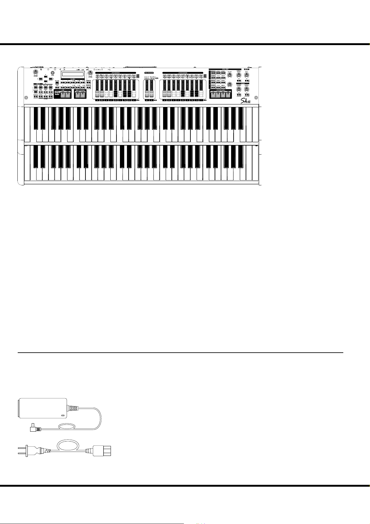
Skx
STAGE KEYBOARD
ank you, and congratulations on your choice of the Hammond SKX
Stage Keyboard.
e Hammond SKX features authentic Hammond Organ Sound along
with high-quality keyboard and orchestral voices to make it the perfect
instrument for all musical occasions.
Please take the time to read this Manual completely in order to full advantage of the many features of your SKX, and please retain it for future
reference.
MIX
BALANCE
EXV1 EXV2
Owner’s Manual
Page 2
2
IMPORTANT SAFETY INSTRUCTIONS
Before using this unit, please read the following Safety instructions, and adhere to them.
Keep this manual close by for easy reference.
In this manual, the degrees of danger are classi ed and explained as follows:
is sign shows there is a risk of death or severe injury if this unit is not properly used
WARNING
CAUTION
as instructed.
is sign shows there is a risk of injury or material damage if this unit is not properly
used as instructed.
*Material damage here means a damage to the room, furniture or animals or pets.
WARNING
Do not open (or modify in any way) the unit or its AC
adaptor.
Do not attempt to repair the unit, or replace parts in
it. Refer all servicing to your retailer, the nearest Hammond Dealer, or an authorized Hammond distributor,
as listed on the “Service” page.
Never use or store the unit in places that are:
Subject to temperature extremes (e.g., direct sun-
light in an enclosed vehicle, near a heating duct,
on top of heat generating equipment)
Damp (e.g., baths, washrooms, on wet oors)
Humid
Exposed to rain
Dusty
Subject to high levels of vibration.
Be sure to use only the AC adaptor supplied with the
unit. And, make sure the line voltage at the installation
matches the input voltage speci ed on the AC adaptor’s case. Other AC adaptors may use a di erent polarity, or be designed for a di erent voltage, their use
could result in damage, malfunction, or electric shock.
Do not excessively twist or bend the power cord, or
place heavy objects on it. Doing so can damage the
cord, producing severed elements and short circuits.
Damaged cords are re and shock hazards!
is unit, either alone or in combination with an am-
pli er and headphones or speakers, may be capable of
producing sound levels that could cause permanent
hearing loss. Do not operate for a extended periods of
time at a high volume level, or at a level that is uncomfortable. If you experience any hearing loss or ringing in the ears, you should immediately stop using the
unit, and consult a physician.
Do not allow any objects (e.g., ammable material,
coins, pins); or liquids of any kind (water, so drinks,
etc.) to penetrate the unit.
Immediately turn the power o , remove the AC adap-
tor from the outlet, and request servicing by your retailer, the nearest Hammond Dealer, or an authorized
Hammond distributor, as listed on the “Service” page
when:
e AC adaptor, the power-supply cord, or the
plug has been damaged; or
If smoke or unusual odor occurs
Objects have fallen into, or liquid has been spilled
onto the unit; or
e unit has been exposed to rain (or otherwise
has become wet); or
e unit does not appear to operate normally or
exhibits a marked change in performance.
In households with small children, an adult should
provide supervision until the child is capable of following all the rules essential for the safe operation of
the unit.
Protect the unit from strong impact. (Do not drop it!)
Do not force the unit’s power-supply cord to share an
outlet with an unreasonable number of other devices.
Be especially careful when using extension cords - the
total power used by all devices you have connected
to the extension cord’s outlet must never exceed the
power rating (watts/amperes) for the extension cord.
Excessive loads can cause the insulation on the cord to
heat up and eventually melt through.
Before using the unit in a foreign country, consult
with your retailer, the nearest Hammond Dealer, or
an authorized Hammond distributor, as listed on the
“Service” page.
Do not put anything that contains water (e.g., ower
vases) on this unit. Also, avoid the use of insecticides,
perfumes, alcohol, nail polish, spray cans, etc., near
the unit. Swi ly wipe away any liquid that spills on the
unit using a dry, so cloth.
Skx
Owner’s Manual
Page 3
CAUTION
3
e unit and the AC adaptor should be located so
their location or position does not interfere with their
proper ventilation.
Always handle the AC adaptor by the plug when plug-
ging into, or unplugging from, an outlet or this unit.
At regular intervals, you should unplug the AC adap-
tor and clean it by using a dry cloth to wipe all dust
and other accumulations away from its prongs. Also,
disconnect the power plug from the power outlet
whenever the unit is to remain unused for an extended
period of time. Any accumulation of dust between the
power plug and the power outlet can result in poor
insulation and lead to re.
Try to prevent cords and cables from becoming en-
tangled. Also, all cords and cables should be placed so
they are out of the reach of children.
FOR UNITED KINGDOM:
FOR YOUR SAFETY, PLEASE READ THE FOLLOWING
TEXT CAREFULLY
is appliance is supplied with a molded 3-pin mains plug for
your safety and convenience.
e plug contains a 13 amp fuse.
Should the fuse need to be replaced, please ensure that the re-
placement fuse has a rating of 13 amps and that it is approved
by ASTA or BSI to BSI1362.
Check for the ASTA mark or the BSI mark on the
body of the fuse.
If the fuse cover is lost, the plug must not be used until a replacement cover is obtained.
A replacement fuse cover can be obtained from your local
Hammond Dealer.
If the tted moulded plug is unsuitable for the socket outlet in
your home, then the fuse should be removed and the plug cut
o and disposed of safely.
ere is a danger of severe electrical shock if the cut-o plug is
inserted into any 13 amp socket.
To replace the fuse, open the fuse compartment with a screwdriver and replace the fuse and fuse cover.
Never climb on top of or place heavy objects on the
unit.
Never handle the AC adaptor or its plugs with wet
hands when plugging into, or unplugging from, an
outlet of this unit.
Before moving the unit, disconnect the AC adaptor
and all cords coming from external devices.
Before cleaning the unit, turn o the power and un-
plug the AC adaptor from the outlet.
Whenever you suspect the possibility of lightning in
your area, disconnect the AC adaptor from the outlet.
Note: is equipment has been tested and found to comply
with the limits for a Class B digital device, pursuant to part 15
of the FCC Rules. ese limits are designed to provide reasonable protection against harmful interference in a residential
installation.
is equipment generates, uses and can radiate radio frequency
energy and, if not installed and used in accordance with the
instructions, may cause harmful interference to radio communications.
However, there is no guarantee that interference will not occur
in a particular installation.
If this equipment does cause harmful interference to radio or
television reception, which can be determined by turning the
equipment o and on, the user is encouraged to try to correct
the interference by one or more of the following measures:
Reorient or relocate the receiving antenna.
Increase the separation between the equipment and re-
ceiver.
Connect the equipment into an outlet on a circuit di erent
from that to which the receiver is connected.
Consult the dealer or an experienced radio/TV technician
for help.
In the unlikely event that you need to dispose of
this unit, be sure to contact your dealer or your
nearest town or municipal office for its proper
disposal.
Introduction
Page 4

4
IMPORTANT - PLEASE READ
Power Supply
Do not use this unit on the same power circuit with any
device that will generate line noise (such as an electric motor or light dimming system).
e AC adaptor will begin to generate heat after long hours
of consecutive use. is is normal, and is not a cause for
concern.
Before connecting this unit to other devices, turn o the
power to all units. is will help prevent malfunctions and/
or damage to speakers or other devices.
Placement
Using the unit near power ampli ers (or other equipment
containing large power transformers) may induce hum. To
alleviate the problem, change the orientation of this unit, or
move it farther away from the source of interference.
is device may interfere with radio and television recep-
tion. Do not use this device in the vicinity of such receivers.
Noise may be produced if wireless communications devices,
such as cell phones, are operated in the vicinity of this unit.
Such noise could occur when receiving or initiating a call,
or while conversing. Should you experience such problems,
you should relocate such wireless devices so they are at a
greater distance from this unit, or switch them o .
Do not expose the unit to direct sunlight, place it near
devices that radiate heat, leave it inside an enclosed vehicle,
or otherwise subject it to temperature extremes. Also, do
not allow lighting devices that normally are used while
their light source is very close to the unit (such as a piano
light), or powerful spotlights to shine upon the same area
of the unit for extended periods of time. Excessive heat can
deform or discolor the unit.
When moved from one location to another where the tem-
perature and/or humidity is very di erent, water droplets
(condensation) may form inside the unit. Damage or malfunction may result if you attempt to use the unit in this
condition. erefore, before using the unit, you must allow
it to stand for several hours, until the condensation has
completely evaporated.
Do not allow rubber, vinyl, or similar materials to remain
on the unit for long periods of time. Such objects can discolor or otherwise harmfully a ect the nish.
Do not paste stickers, decals, or the like on the SKX. Peel-
ing such matter o the SKX may damage the exterior nish.
Additional Precautions
Please be aware that the contents of memory can be irre-
trievably lost as a result of a malfunction, or the improper
operation of the unit. To protect yourself against the risk of
losing important data, we recommend that you periodically
save a backup copy of important data you have stored in the
unit’s memory in another MIDI device (to another storage
medium (such as a USB Flash Drive or an external hard
drive).
Unfortunately, it may be impossible to restore the contents
of data once it has been lost. Hammond assumes no liability concerning such loss of data.
Use a reasonable amount of care when using the unit’s but-
tons, sliders, or other controls, and when using its jacks and
connectors. Rough handling can lead to malfunctions.
When connecting / disconnecting all cables, grasp the con-
nector itself - never pull on the cable. is will avoid causing short circuits, or damage to the cable’s internal elements.
To avoid disturbing your neighbors, try to keep the unit's
volume at reasonable levels. You may prefer to use headphones, so you do not need to be concerned about those
around you (especially when it is late at night).
When you need to transport the unit, package it in the box
(including padding) that it came in, if possible. Otherwise,
you will need to use equivalent packaging materials.
Disclaimer
All trademarks and brand names mentioned in this manual are
the property of their respective owners and not in any way af liated or associated with Hammond Suzuki. e trademarks
are only mentioned for explanation purposes.
Maintenance
To clean the unit, use a dry, soft cloth; or one that is slightly
dampened.
To remove stubborn dirt o plastic parts, use a cloth im-
pregnated with a mild, non-abrasive detergent. Afterwards,
be sure to wipe the unit thoroughly with a soft, dry cloth.
Try to wipe the entire surface using an equal amount of
strength, moving the cloth along with the grain of the
wood. Rubbing too hard in the same area can damage the
nish.
Never use benzine, thinners, alcohol or solvents of any
kind, to avoid the possibility of discoloration and/or deformation.
Skx
Owner’s Manual
Page 5

5
INTRODUCTION
Introduction
Page 6

6
TableOfContents
IMPORTANT SAFETY INSTRUCTIONS ................................................ 2
IMPORTANT - PLEASE READ ................................................................. 4
INTRODUCTION ........................5
MAIN FEATURES ....................................................................................... 9
NAMES AND FUNCTIONS ...................................................................10
TOP PANEL ......................................................................................................10
REAR PANEL ...................................................................................................13
KEYBOARD ......................................................................................................14
ACCESSORIES .................................................................................................14
MULTI-EFFECTS ....................................................................................................29
ALLOCATING THE EXTRA VOICES............................................................30
SELECT AN INSTRUMENT ..........................................................................30
ADJUST THE VOLUME BALANCE .............................................................30
Column: To select the other group (e.g.“Wind”) .......................................30
ADD EFFECTS TO THE EXTRA VOICE SECTION ...................................31
MULTI-EFFECTS ....................................................................................................31
ADD REVERB TO BOTH SECTIONS ..........................................................31
REVERB ....................................................................................................................31
WHAT IS A “PART”? .......................................................................................32
MANUAL BASS ..............................................................................................32
LOWER TO PEDAL .........................................................................................33
PEDAL SUSTAIN ............................................................................................33
RECORD THE PATCH TO MEMORY ..........................................................34
Example: RECORD TO U032 .............................................................................34
HOOK-UP .................................15
BASIC HOOK-UP .....................................................................................16
CONNECTING THE LESLIE SPEAKER ................................................17
BASIC CONNECTION ...................................................................................17
USING 3 CHANNEL TYPE (SUCH AS 2101/mk2) ........................................17
USING SINGLE CHANNEL TYPE (SUCH AS 122XB, 3300/W) ..................17
MIDI CONTROL OF THE LESLIE SPEAKER .............................................17
EXPAND THE KEYBOARD ..................................................................... 18
PEDALBOARD (13 OR 20 KEYS) ...............................................................18
PEDALBOARD (25 KEYS) ............................................................................19
GETTING READY TO PLAY .......21
SWITCH ON ..............................................................................................22
HOW TO POWER ON ...................................................................................22
BACK UP ..........................................................................................................22
AUTO POWER OFF .......................................................................................22
RESET TO THE FACTORY SETTINGS ........................................................22
PLAY WITH THE PATCHES ....................................................................23
“USER” AND “PRESET” .................................................................................23
HOW TO CALL A PATCH ..............................................................................23
Example: Select U041. .......................................................................................23
REGISTER FAVORITE PATCHES (FAVORITES) ..................................24
Register PATCHES to FAVORITES .............................................................24
Ex. Register U041 to “3-2” ..................................................................................24
How to recall FAVORITES ...........................................................................24
Ex. Call the “3-2” ....................................................................................................24
BANK and NUMBER .....................................................................................24
Column: RECORD FAVORITES LIKE PRESET BUTTONS .....................25
USE THE FOOT CONTROLLERS ..........................................................26
EXPRESSION PEDAL ....................................................................................26
FOOT SWITCH ................................................................................................26
DAMPER PEDAL ............................................................................................26
TRY CREATING YOUR OWN SOUND .................................................27
SELECT [MANUAL] .......................................................................................27
Column: INITIALIZE THE INTERNAL SETTINGS [MANUAL] .............27
SWITCH THE ORGAN SECTION ON .........................................................28
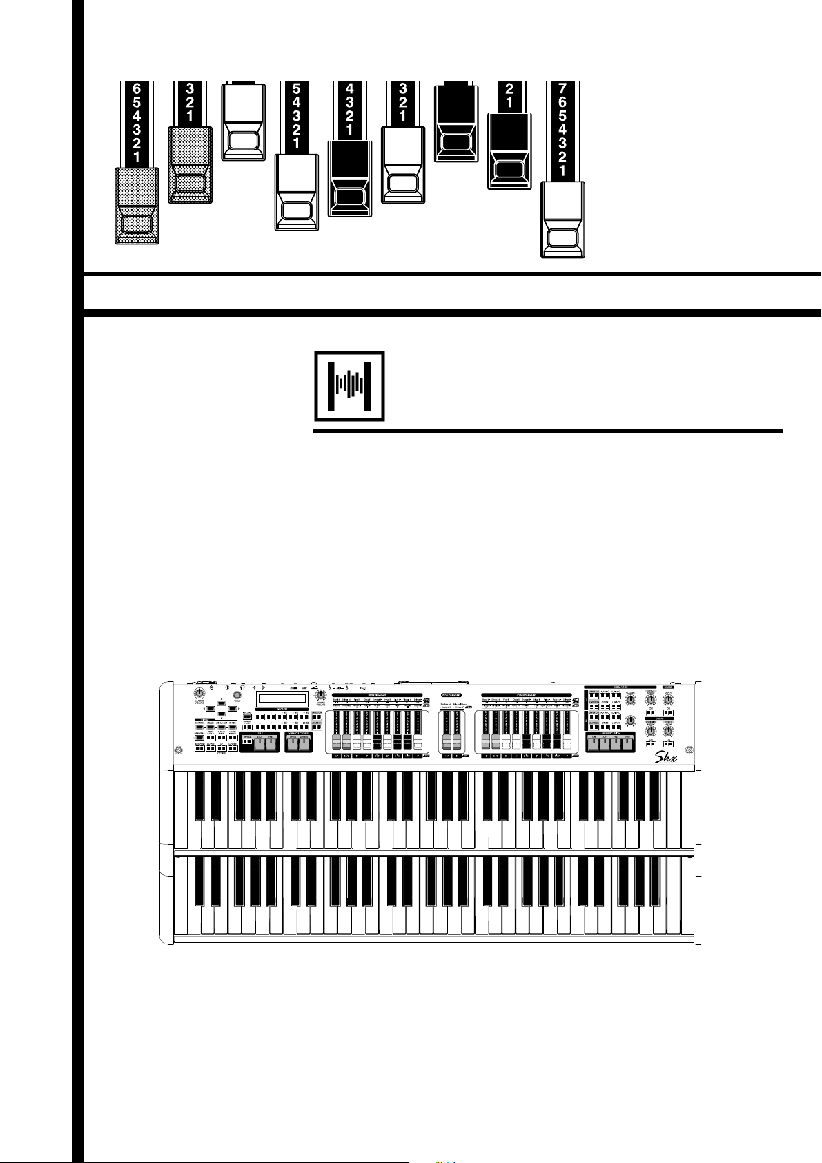
PULL OUT DRAWBARS ................................................................................28
ADD THE TOUCH-RESPONSE PERCUSSION .........................................28
ADD EFFECTS TO THE ORGAN SECTION ..............................................29
VIBRATO & CHORUS ............................................................................................29
LESLIE .......................................................................................................................29
OVERDRIVE ............................................................................................................29
SETTING UP .............................35
SOUND ENGINE STRUCTURE .............................................................36
ORGAN SECTION ..........................................................................................37
EXTRA VOICE SECTION ...............................................................................37
MASTER EQUALIZER ....................................................................................37
ORGAN SECTION ....................................................................................38
ORGAN TYPE ..................................................................................................38
TONE-WHEELS (BType1, BType2, Mellow) ..................................................38
TRANSISTOR (Vx, Farf) .......................................................................................38
PIPE ...........................................................................................................................38
Column: SELECTING THE ORGAN TYPES..............................................39
Example: Switching the Organ Type to “Pipe” ...........................................39
HARMONIC DRAWBARS™ ...................................................................40
DRAWBARS (ON TONE-WHEEL: BType1, BType2, Mellow) .............40
DRAWBARS FOR THE UPPER AND LOWER PARTS .............................41
DRAWBARS TO USE ON THE PEDAL .......................................................41
DRAWBAR REGISTRATION PATTERNS....................................................42
MODERN DRAWBAR REGISTRATIONS ...................................................43
DRAWBARS (Vx) ............................................................................................44
DRAWBARS (Farf) .........................................................................................45
DRAWBARS (PIPE) ........................................................................................46
OPERATING ORGAN SECTION ...........................................................47
ON / OFF AND VOLUME CONTROL ........................................................47
MATCH THE REGISTRATION TO DRAWBARS ........................................47
PERCUSSION ............................................................................................48
1´ DRAWBAR CANCEL ........................................................................................48
VIBRATO & CHORUS ..............................................................................49
TO SELECT THE VIBRATO & CHORUS MODE ...............................................49
OVERDRIVE...............................................................................................50
LESLIE .........................................................................................................51
MULTI-EFFECTS, REVERB .....................................................................52
PEDAL SUSTAIN, COUPLER .................................................................53
OCTAVE SHIFT .........................................................................................54
TRANSPOSE .............................................................................................55
EXTRA VOICE SECTION ........................................................................56
ALLOCATE .......................................................................................................56
BUILT IN SOUNDS AND LIBRARY .............................................................56
MULTI-EFFECTS, REVERB .....................................................................57
PATCH .........................................................................................................58
“USER” AND “PRESET” .................................................................................58
NAME THE PATCH .........................................................................................59
Skx
Owner’s Manual
Page 7
7
RECORD TO THE PATCH ..............................................................................60
Example: RECORD TO “U032” ...........................................................................60
USING THE CONTROL PANEL ..61
WHAT YOU CAN DO ON THE CONTROL PANEL ...........................62
PLAY MODE ..............................................................................................63
HOW TO READ THE DISPLAY ....................................................................63
OPERATION IN THIS MODE .......................................................................63
MENU MODE ...........................................................................................64
HOW TO READ THE DISPLAY ....................................................................64
OPERATION IN THIS MODE .......................................................................64
MENU AND THE CONTENTS .....................................................................65
FUNCTION MODE ..................................................................................66
HOW TO READ THE DISPLAY ....................................................................66
OPERATION IN THIS MODE .......................................................................66
PARAMETER OPERATION EXAMPLE: ......................................................67
SHORT CUT TO FUNCTION MODE ...................................................69
OPERATION EXAMPLE: ...............................................................................69
REGISTER THE PAGES YOU FREQUENTLY USE ..............................69
OPERATION EXAMPLE: ...............................................................................69
DISPLAY LOCK MODE ...........................................................................70
SETTING THE PARAMETERS ...71
DRAWBAR .................................................................................................72
SETTING FOR MANUAL (LOWER & UPPER) DRAWBARS ....................72
SETTING THE PEDAL PART ...........................................................................73
PATCH .........................................................................................................74
PATCH NAME ....................................................................................................74
PATCH LOAD .....................................................................................................74
FAVORITES ......................................................................................................... 74
EXVOICE (Extra Voices) ........................................................................75
CONTROL ..................................................................................................76
FOOT SWITCH...................................................................................................76
EXPRESSION ......................................................................................................77
GLIDE...................................................................................................................78
DAMPER .............................................................................................................78
ASSIGN................................................................................................................78
DISPLAY ..............................................................................................................79
KEYBOARD ........................................................................................................79
PART.....................................................................................................................79
PERCUSS (Percussion) ..........................................................................80
VIB&CHO (Vibrato & Chorus) .............................................................81
LESLIE .........................................................................................................82
CABINET NUMBER ..........................................................................................82
LESLIE PARAMETERS ......................................................................................82
EXTERNAL LESLIE SPEAKER .........................................................................84
RECORD THE CABINET ................................................................................84
CUST. TW (Custom Tone-Wheels) ....................................................85
Record the CUSTOM virtual Tone Wheels ...........................................87
PIPE .............................................................................................................88
OD / EFF (Overdrive / Effects) ............................................................90
ORGAN SECTION EFFECTS ...................................................................90
OVERDRIVE ............................................................................................................90
MULTI-EFFECTS ....................................................................................................91
EFFECTS FOR THE EXTRA VOICE SECTION ......................................97
OVERDRIVE ............................................................................................................97
MULTI-EFFECTS ....................................................................................................97
EQUALIZ (Equalizer) ..............................................................................98
ORGAN SECTION .............................................................................................98
ORGAN SECTION, EXTRA VOICE SECTION, MASTER ...........................98
REVERB ......................................................................................................99
TUNE ....................................................................................................... 100
MASTER TUNE ...............................................................................................100
DEFAULT ................................................................................................. 101
SYSTEM ................................................................................................... 102
MIDI .......................................103
ABOUT MIDI .......................................................................................... 104
WHAT IS “MIDI”? ........................................................................................104
MIDI JACKS ON THE SKX .........................................................................104
WHAT THE MIDI CAN DO ON THE SKX ............................................... 104
WHAT IS A “MIDI TEMPLATE?” ...............................................................104
MIDI CHANNEL ...........................................................................................105
MAIN MIDI MESSAGE ...............................................................................105
CHANNEL MESSAGE ........................................................................................ 105
SYSTEM MESSAGE ............................................................................................ 105
MIDI STRUCTURE ................................................................................106
KEYBOARD CHANNELS .............................................................................. 107
EXTERNAL ZONE CHANNELS ................................................................... 107
EXPANDED KEYBOARDS ............................................................................ 107
USING AN EXTERNAL SEQUENCER ............................................... 108
Recording a performance to an external sequencer ...................... 108
Sequencer playback ...................................................................................108
USING A MIDI SOUND MODULE .................................................... 109
ZONES ..................................................................................................... 110
WHAT IS DISPLAYED ON THE UPPER LEFT? .........................................110
INTERNAL ZONE ........................................................................................... 110
EXTERNAL ZONE .......................................................................................... 110
PANIC FUNCTION AND PARAMETER RE-LOAD ....................................... 111
MIDI ......................................................................................................... 112
MIDI TEMPLATE ............................................................................................. 112
MASTER ........................................................................................................... 112
KEYBOARD CHANNELS .............................................................................. 113
SAVE THE SETUP ...................115
SAVE YOUR SETUP .............................................................................. 116
WHAT YOU CAN DO WITH THE USB FLASH DRIVE .........................116
ABOUT USB FLASH DRIVE ......................................................................116
USABLE USB FLASH DRIVE ............................................................................116
USB FLASH DRIVE CONNECTOR ..................................................................116
FOLDER STRUCTURE .......................................................................................116
INITIALIZE THE USB FLASH DRIVE ................................................. 117
WORKING WITH SETUPS .................................................................. 118
HOW TO READ THE DISPLAY .................................................................118
SAVING THE SETUP ................................................................................... 118
CHANGING THE SETUP NAME .............................................................. 119
LOADING THE SETUP ...............................................................................120
DELETING THE SETUP .............................................................................. 120
WORKING WITH PATCHES ................................................................121
HOW TO READ THE DISPLAY .................................................................121
SAVING THE PATCH ................................................................................... 121
LOADING A PATCH ....................................................................................122
DELETING THE PATCH ..............................................................................122
Introduction
Page 8

8
WORKING WITH CUSTOM TONE WHEEL ..................................... 123
HOW TO READ THE DISPLAY .................................................................123
SAVE THE CUSTOM TONE WHEEL FILE ............................................... 123
LOADING A CUSTOM TONE WHEEL ....................................................124
DELETING A CUSTOM TONE WHEEL ...................................................124
MUSIC PLAYER ......................125
BEFORE PLAYING BACK ....................................................................126
FILE TYPE AND PLACING FOLDER .......................................................126
HOW TO READ THE DISPLAY .................................................................126
WORKING WITH THE MUSIC PLAYER ............................................ 127
MUSIC PLAYER MODES ...........................................................................128
VOICE LIBRARY .....................129
WHAT IS VOICE LIBRARY? ................................................................. 130
FILE TYPE AND THE PLACING FOLDER ...............................................130
VOICE LIBRARY AND SETUPS ................................................................130
WORKING WITH VOICE LIBRARY .................................................... 131
LOADING THE VOICE LIBRARY ..............................................................131
DELETE A VOICE LIBRARY .......................................................................132
CLEAR ALL VOICE LIBRARIES ................................................................. 132
Troubleshooting ...................133
TROUBLESHOOTING .......................................................................... 134
APPENDIX ..............................135
EXTRA VOICE INSTRUMENT LIST ................................................... 136
PRESET PATCH LIST............................................................................. 138
MIDI TEMPLATES ................................................................................. 139
MIDI TEMPLATES ....................................................................................... 139
MIDI INFORMATION ........................................................................... 140
MIDI Implementation .............................................................................. 140
Channel Voice Message ................................................................................ 140
Channel Mode Message ................................................................................140
Drawbar Data List 1 ..................................................................................141
Control Number ................................................................................................ 141
Drawbar Data List 2 ..................................................................................141
System Exclusive Message.....................................................................142
Mode Setting Exclusive Message ...............................................................142
NRPN Switch ......................................................................................................142
Data Set (Rx. only) ............................................................................................142
Identity Request (Rx. only) ............................................................................142
Identity Reply (Tx. only) .................................................................................142
Global Parameters .................................................................................... 143
Patch Parameters ......................................................................................144
Leslie Parameters ...................................................................................... 148
System Parameters ...................................................................................148
Tone Wheel Parameters .......................................................................... 148
Pipe Parameters.........................................................................................148
CUSTOM TONE-WHEELS LIST ......................................................... 149
MIDI IMPLEMENTATION CHART ..................................................... 150
MIDI CHANNELS AND MESSAGES ................................................. 151
SPECIFICATIONS .................................................................................. 152
SERVICE .................................................................................................. 155
Skx
Owner’s Manual
Page 9

MAIN FEATURES
AUTHENTIC HAMMOND DRAWBAR ORGAN
e SKX is rst and foremost a genuine Hammond Organ with “Virtual Tone Wheels”
to provide the classic Hammond sound. Also available are the tones of vintage “combo”
organs, and a variety of pipe organ ranks to provide church and classical organ voices.
EXTRA VOICE SECTION
e EXTRA VOICE section provides high quality Acoustic and Electric Pianos, as well as
other Keyboard and Orchestral voices. Additional Voice Libraries can be downloaded and
installed using a USB Flash Drive.
e Organ and Extra Voice can be used together, and their outputs can be individually
accessed, using the Leslie Speaker for the Organ section, and the LINE OUT jack(s) for
the Extra Voice section.
DIGITAL LESLIE/VIBRATO
A digital and programmable Leslie is available for the Drawbar voices, as well as the traditional “Vibrato/Chorus” as used on the legendary B-3/C-3. e Vibrato/Chorus may be
selected for the Upper and Lower parts, independently.
A WIDE VARIETY OF EFFECTS
Digital Multi-e ects are available for the Organ and Extra Voice sections independently. A
Master Equalizer allows you to tailor the total tonal response of the SKX.
MUSIC PLAYER
e SKX is equipped to play MP3/WAV type audio les. is makes it very convenient
for accompanying solo performances or practicing.
9
MIDI MASTER KEYBOARD
External Zones are available to enable the SKX to be used as a master keyboard.
PATCHES AND FAVORITES
In addition to the 100 available user-de ned Patches, 10×10 “Favorite” quick-call Patches
are available for on-stage ease.
BUILT-IN USB PORT
is allows you to use a USB Flash Drive to save Patches, Setups, etc. as well as to use the
built-in Music Player, install additional Voice Libraries and update the system software of
the instrument.
LESLIE SOCKET
An 11-pin Leslie receptacle is provided which allows you to use the SKX with a Leslie
Speaker having an 11-pin interface.
SMALL AND LIGHT WEIGHT
e SKX is small and light weight, making transport and setup easy.
Introduction
Page 10
10
❶
❷
❸
❹❹❺❺❻
❼
❽❽❾❾❿
⓫⓫⓬
⓭
⓲
⓳
⓴
⓮
⓯
⓰
⓱
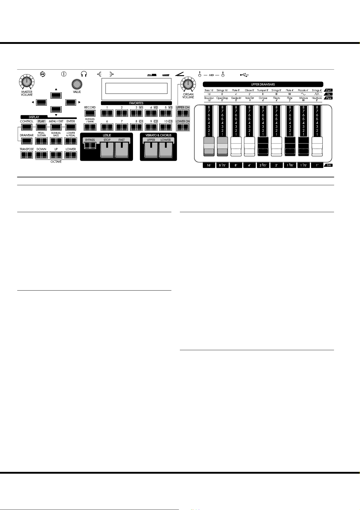
TOP PANEL
❶
⓮
❷
⓬
⓯
⓭
⓱
⓲
NAMES AND FUNCTIONS
⓰
⓴
⓳
❸
❼
❿
❻
UPPER LEFT
❶ MASTER VOLUME knob
Allows you to control the volume of the entire instrument. (P. 22)
❷ CONTROL button
Allows you to access a feature from the CONTROL Function
mode. (P. 76)
❸ DRAWBAR button
Allows you to access the DRAWBAR Function mode to set the
Organ Type etc. (P. 39)
KEYBOARD CONTROL
❹ PEDAL SUSTAIN button
Allows you to add a smooth decay to the PEDAL tones similar
to a string bass. (P. 33)
❺ MANUAL BASS button
Allows you to play the PEDAL tones from the LOWER keyboard. (P. 32)
❻ LOWER to PEDAL button
Allows you to play the tones from the LOWER part from a
connected MIDI Pedalboard. (P. 33)
❼ TRANSPOSE button
Allows you to shift the musical key of the entire instrument.
(P. 55)
❽ OCTAVE DOWN button
❾ OCTAVE UP button
ese two buttons allow you to move the pitch of the UPPER
part “UP” or “DOWN” by one octave. (P. 54)
❿ OCTAVE LOWER button
Allows you to move the pitch of the LOWER part “UP” or
“DOWN” by octaves when used in conjunction with the OCTAVE DOWN/UP buttons. (P. 54)
CONTROL PANEL
⓫ PLAY button
Allows you to return to the Play, or basic mode. (P. 63)
⓬ MENU/EXIT button
Allows you to access Menu mode in the display and return to
the Menu mode from other Function modes. (P. 64)
⓭ VALUE knob
Allows you to increases/decrease Patch numbers while performing or adjusts values during editing.
⓮ DIRECTION buttons
Allows you to move the cursor in the display or locate other
pages.
⓯ ENTER button
Allows you to con rm the current entry or procedure when
editing sounds or features.
⓰ DISPLAY
FAVORITES
⓱ RECORD button
Allows you to record user-de nable features such as Patches,
Favorites, etc. (P. 34)
⓲ MANUAL/BANK button
Allows you to override the current Patch setting in favor of the
current Panel settings. (P. 27)
Also, allows you to selects Favorite Banks by pressing this button with one of the numbered FAVORITE buttons. (P. 24)
⓳ NUMBER buttons
Allows you to recall Patches you frequently use quickly. (P. 24)
Skx
Owner’s Manual
Page 11
BALANCE
EXV1 EXV2
11
MIX
ORGAN SECTION
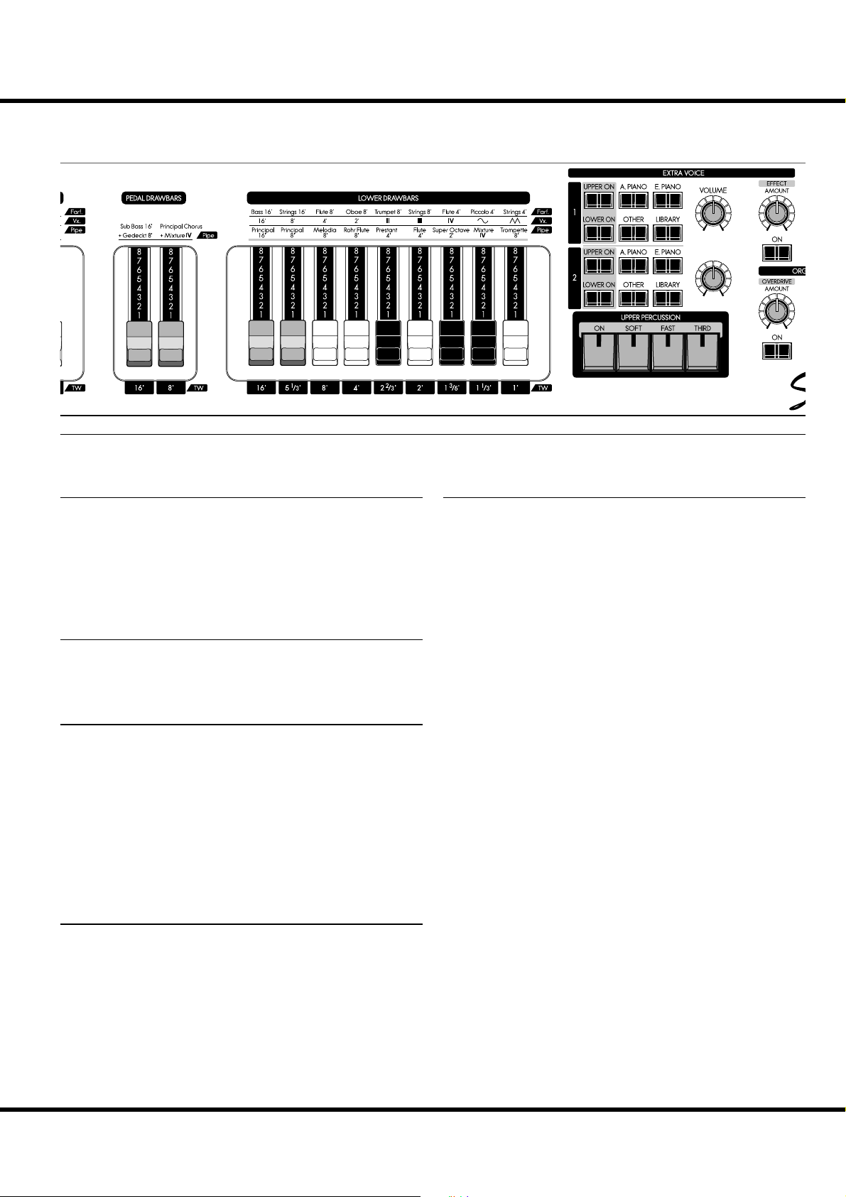
⓴ UPPER ON, LOWER ON buttons
Allows you to “sound” or “mute” each part of the Organ section.
ORGAN VOLUME knob
Allows you to controls the volume of the entire Organ section.
(P. 47)
VIBRATO & CHORUS
UPPER, LOWER buttons
Allows you to select which part receives the Vibrato & Chorus
E ect. (P. 49)
LESLIE
BYPASS button
Allows you to direct the sounds produced by the Organ section
from the Rotary channel to the Stationary channel. (P. 51)
STOP button
Allows you to stop the Leslie Rotors from turning when the
[FAST] button is “OFF”. (P. 51)
FAST button
Toggles the modes of the Rotors FAST or not. When the light
is ON, it is FAST. (P. 51)
PERCUSSION
ON button
Allows you to add the Percussion e ect to the UPPER part.
(P. 48)
SOFT button
Allows you to select “NORMAL” or “SOFT” Percussion volume. (P. 48)
FAST button
Allows you to select “SLOW” or “FAST” Percussion decay
time. (P. 48)
THIRD button
Allows you to select “SECOND” (4´) or “THIRD” (2 ⅔ ´)
Percussion harmonic. (P. 48)
DRAWBARS
ese are for adjusting the basic harmonics of the Organ section. e function of each drawbar is di erent depending on
the type of Organ (Tone Wheel/Transistor/Pipe). (P. 40)
UPPER Drawbars
Allows you to adjust the UPPER part.
PEDAL Drawbars
Allows you to adjust the PEDAL part.
LOWER Drawbars
Allows you to adjust the LOWER part.
Introduction
Page 12
NAMES AND FUNCTIONS - continued
12
BALANCE
MIX
EXTRA VOICES
ALLOCATE UPPER, LOWER button
Allows you to assign the Extra Voice sections to either the UPPER, and LOWER parts. (P. 56)
VOICE GROUP buttons
Allows you to select the Voice Group of the Extra Voice sections. (P. 30)
VOLUME knob
Allows you to adjust the entire volume of the Extra Voice sections. (P. 30)
BALANCE knob
Allows you to adjust the balance between Extra Voice sections
1 and 2. (P. 30)
EXV1 EXV2
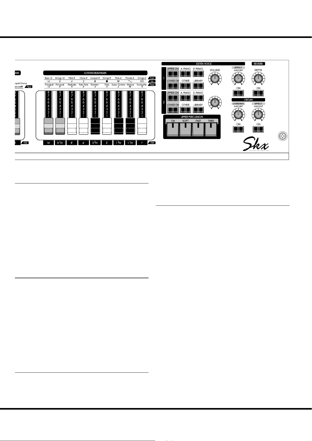
EXTRA VOICE EFFECT AMOUNT knob
Allows you to adjust the amount of the selected Extra Voice
Multi-E ects. (P. 57)
EFFECTS FOR ALL PARTS
REVERB ON button
Allows you to turn the Reverb e ect “ON” or “OFF”. (P. 52)
REVERB DEPTH knob
Allows you to adjust the depth of the Reverb. (P. 52)
EFFECTS FOR THE ORGAN SECTION
DRAWBARS OVERDRIVE ON button
Allows you to turn the Organ Overdrive effect “ON” or
“OFF”. (P. 50)
DRAWBARS OVERDRIVE AMOUNT knob
Allows you to adjust the amount of the Organ Overdrive effect. (P. 50)
DRAWBARS EFFECT ON button
Allows you to turn the selected Organ Multi-E ect “ON” or
“OFF”. (P. 52)
DRAWBARS EFFECT AMOUNT knob
Allows you to adjust the amount of the Organ Multi-E ects.
(P. 52)
EFFECTS FOR THE EXTRA VOICE SECTION
EXTRA VOICE EFFECT ON button
Allows you to turn the selected Extra Voice Multi-E ect “ON”
or “OFF”. (P. 57)
Skx
Owner’s Manual
Page 13
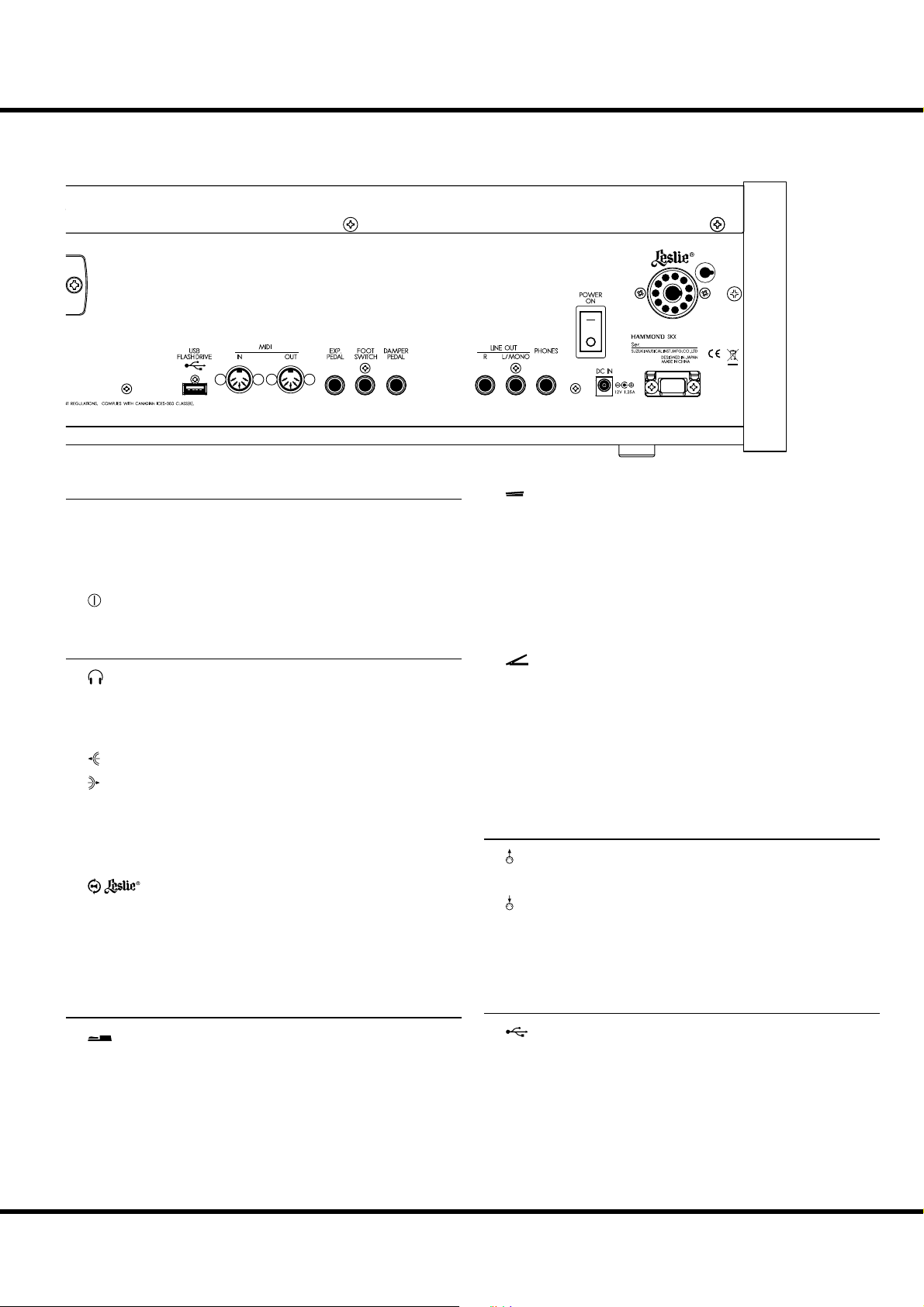
REAR PANEL
❿
⓬
⓫
❾❾❽
❼
❻
❺❺❹❹❸
❷
❶
⓬
⓫
❿
❽
❼
❸
❷
❶
❻
13
11 P I N
POWER
❶ DC IN jack
Connect the AC adaptor AD3-1250-2P to this jack.
Use with strain relief to avoid accidentally disconnecting the
power during performance. (P. 16)
❷ POWER switch
Turns the power to the SKX “ON” or “OFF.” (P. 22)
AUDIO OUTPUT TERMINALS
❸ PHONES jack
Connect a set of stereo headphones to this jack.
NOTE: Connecting Headphones does NOT mute the LINE OUT or
LESLIE audio outputs.
❹ LINE OUT L/MONO jack
LINE OUT R jack
❺
Use these jacks to connect an external audio equipment.
If the connected mixer or monitor speaker is stereophonic,
connect both L and R. If monaural, connect only to the L/
MONO jack (P. 16) and set the Audio Mode at “MONO” (P. 102).
❻
LESLIE 11 PIN socket
Connect a Leslie Speaker equipped with an 11-pin interface
here.
When the connection of a physical Leslie Speaker is detected, the on-board digital Leslie Simulator is disabled at the
PHONES jack and the LINE OUT jacks. (P. 17)
CONTROLLER TERMINALS
❼ DAMPER PEDAL jack
Connect an optional Damper Pedal (optional VFP1 etc.) here.
If you press the connected Damper Pedal while holding down
keys, the sound is sustained even after you release the key(s)
similar to the damper pedal on an acoustic piano. (P. 78)
NOTE: Use ONLY a Damper Pedal equipped with a Monaural con-
necting plug. DO NOT use a pedal having a Stereo or “TRScompatible” plug, as it will not function.
❽ FOOT SWITCH jack
Connect the Foot Switch here.
Please see (P. 76) for information about the di erent functions
available for the Foot Switch.
e following Foot Switches / Damper Pedals can be used with
SKX:
HAMMOND VFP1, FS-9H
BOSS FS-5U
YAMAHA FC4A, FC5
❾ EXP. PEDAL jack
Connect an optional Expression Pedal here.
is allows you to control the volume while playing. (P. 77)
e following Expression/Volume Pedals can be used with the
SKX:
HAMMOND EXP-50J, EXP-20, V-20H, V-20R; NORM
KORG XVP-10, XVP-20; REV
Roland EV-5; NORM
YAMAHA FC7; REV
MIDI TERMINALS
❿ MIDI OUT jack
MIDI data is transmitted from this jack. (P. 104)
⓫ MIDI IN jack
MIDI data is received via this jack.
NOTE: The SKX is factory-programmed to receive incoming MIDI
data from a connected MIDI Pedalboard regardless of the current MIDI Channel setting. (P. 104)
USB TERMINAL
⓬ USB FLASH DRIVE port
Use this port to connect a USB Flash drive. (P. 116)
Introduction
Page 14
NAMES AND FUNCTIONS - continued
❶
❷
❶
❷
14
KEYBOARD
PLAYER
❶
❷
MIX
BALANCE
EXV1 EXV2
❶ UPPER keyboard
61 Square-front (“waterfall”-style) keys, velocity sensitive.
is is for playing the UPPER part.
❷ LOWER keyboard
61 Square-front (“waterfall”-style) keys, velocity sensitive.
is is for playing the LOWER part.
ACCESSORIES
❶
❷
Skx
Owner’s Manual
❶ AC adaptor
Supplies power to the SKX.
NOTE: Use only a Hammond-approved AC adaptor AD3-1250-2P,
DO NOT substitute another similar-looking AC adaptor.
❷ AC cord set
Plug one end into AC adaptor and the other end into an AC
wall outlet.
Page 15

15
HOOK-UP
Page 16
16
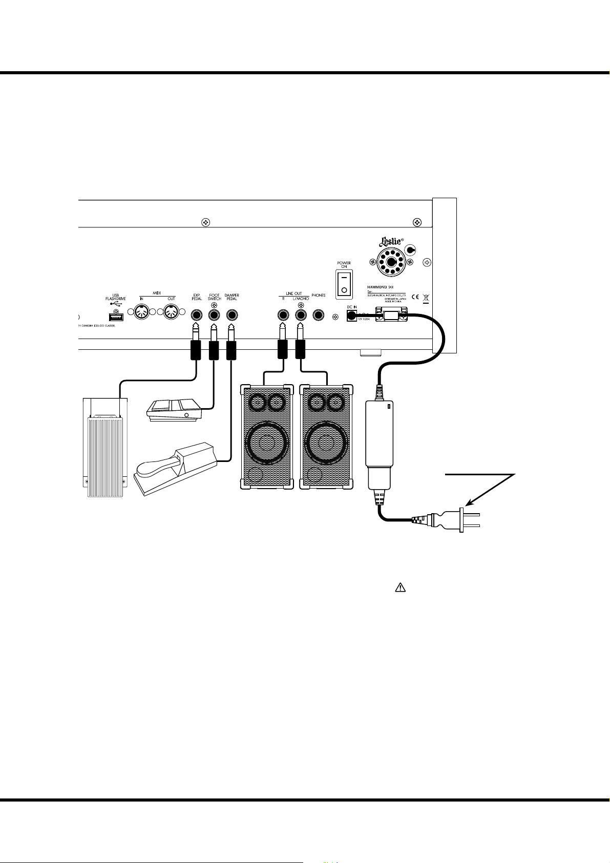
BASIC HOOK-UP
Connect audio cables and accessories as shown below.
e SKX is not self-contained - an external ampli er/speaker system is required in
order to hear the sound. However, if you connect a set of stereo headphones to the
PHONES jack, you can hear the sound through the headphones even if an external
ampli er is not connected.
NOTE: Make sure both the instrument and ampli er are “OFF” before connecting ampli ers
or headphones.
11 P I N
Foot Switch
FS-9H (optional)
Damper Pedal
Expression Pedal
EXP-50J (optional)
e Expression Pedal and Foot Switch parameters must be set properly. For details
see [CONTROL]. (P. 76)
Set Audio Mode either stereo or mono connection. (P. 102)
VFP1 (optional)
Powered Speakers
(optional)
AC adaptor
AD3-1250-2P (included)
to AC outlet
CAUTION
Do not place this unit in direct sun
light, near heat sources, or in a hot
location.
Skx
Owner’s Manual
Page 17
11 PI N
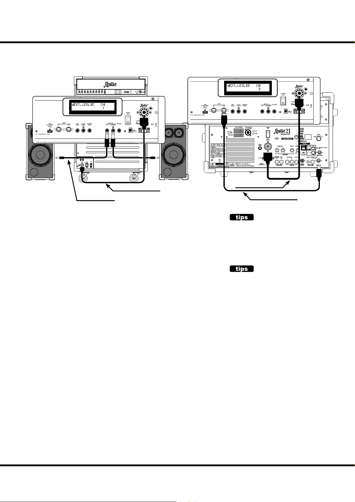
CONNECTING THE LESLIE SPEAKER
11 PI N
An 11-pin type Leslie speaker can be directly connected to SKX.
NOTE: Switch OFF before connecting the Leslie speaker.
Connecting with single channel type Connecting with 3 channel type
17
11-pin Leslie Cable
Phone Cable
BASIC CONNECTION
USING 3 CHANNEL TYPE (SUCH AS 2101/mk2)
1. Connect the Leslie Speaker and the Leslie 11-PIN socket on the SKX with the
exclusive 11-pin Leslie cable (optional LC-11-7M, not included).
2. Turn on the power, and set the EXT. LESLIE CH parameter at “3”. (P. 84)
3. Make the setting of Tone Wheel organ.
4. Switch “ON” the [BYPASS] button, set the [STATIONARY VOLUME] of the
Leslie Speaker at desired volume.
5. Repeat “ON/OFF” the [BYPASS] button with playing the keyboard, set the
[ROTARY VOLUME] of the Leslie Speaker at same volume which you can hear.
USING SINGLE CHANNEL TYPE (SUCH AS 122XB, 3300/W)
1. Connect the Leslie Speaker and the Leslie 11-PIN socket on the SKX with the
exclusive 11-pin Leslie cable (optional LC-11-7M, not included).
2. Connect the audio equipment such as powered speakers and Line Out of the
SKX with audio cable.
3. Turn on the power, and set the EXT. LESLIE CH parameter at “1”. (P. 84)
4. Make the setting of Tone Wheel organ.
5. Switch “ON” the [BYPASS] button, set the audio equipment at desired volume.
6. Repeat “ON/OFF” the [BYPASS] button with playing the keyboard, set the
[VOLUME] of the Leslie Speaker at same volume which you can hear.
11-pin Leslie Cable
MIDI Cable (Optional)
LESLIE SPEAKERS TO BE CON-
NECTED
The SKX is designed to connect with 3 channel Leslie speakers such as 2101/mk2. However, it is also
possible to connect 1 channel type Leslie speakers such as 122XB, 3300/W sending the stationary
channels to the LINE OUT jacks independently. (P. 84)
LESLIE CHANNEL
3 channel type Leslie speakers are equipped with
a stereo speaker system, independent of the Rotor,
to provide stereo sound for the Extra Voices and
direct organ sounds.
A traditional single-channel Leslie speakers, such
as a #122 or #147 has no stationary speaker system, thus requiring a separate ampli er/speaker
for the Extra Voices or direct organ sounds.
MIDI CONTROL OF THE LESLIE SPEAKER
To control the parameters of the Leslie Speaker 2101/mk2 ( ne adjustment of the
Rotor speed or the rise time, etc.):
1. Connect the MIDI OUT of the SKX with the MIDI IN of the Leslie Speaker
with a MIDI cable.
2. Set the Keyboard channel - TX UPPER and the Leslie MIDI channel to the same
channel. (P. 113)
When the SKX detects that the Leslie Speaker is connected, the Leslie parameters
sent through MIDI from the SKX are switched from the SKX original to those for
the Leslie Speaker.
Hook-Up
Page 18
18
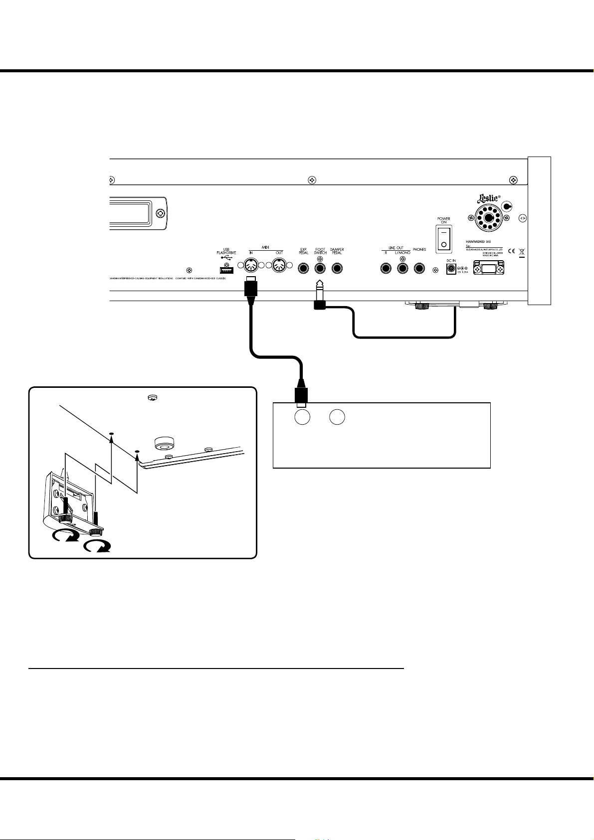
EXPAND THE KEYBOARD
e SKX can be upgraded to dual keyboards by connecting an external MIDI Pedalboard.
PEDALBOARD (13 OR 20 KEYS)
11 P I N
INOUT
MOUNTING THE CU-1(optional)
1. Connect the MIDI OUT of the MIDI pedalboard to the MIDI IN of the SKX with a
MIDI cable.
2. When using a Leslie Switch CU-1, connect the CU-1 to the FOOT SWITCH jack.
NOTE: This illustration shows only the Pedalboard expansion. See P.16 for the basic hook up of the power
source, audio, etc.
3. Switch ON the power of the SKX and call the MIDI template “Pedal KBD”. (P. 112)
4. When using the CU-1, set the CONTROL - FOOT DEVICE” at “CU-1”. (P. 76)
RECOMMENDED MIDI PEDALBOARDS
e following MIDI pedalboards are recommended for use with SKX:
MIDI sound pedalboard XPK-130G (13 keys)
MIDI sound pedalboard XPK-200G (20 keys)
MIDI sound pedalboard XPK-200GL (20 long keys)
XPK-100, -200, -200L also can be used.
MIDI Pedalboard
Skx
Owner’s Manual
Page 19

PEDALBOARD (25 KEYS)
MIDI Cable
Stereo Phone Cable LIS-200
Mono Phone Cable
19
11 P I N
AC Adaptor:
AD1-1210 (100-120V region)
AD3-1210 (220-240V region)
Separately purchased
The cables which lined
are separately purchased.
FOOT SW
EXPRESSION
MIDI OUT
DC IN
If using with Leslie Switch CU-1 together, the foot switch on the
XPK-250W can be used as a Damper Pedal.
MIDI PEDALBOARD
:2-9
1. Hook up as illustrated above.
2. When using a Leslie Switch CU-1, connect the CU-1 to the FOOT SWITCH
jack.
NOTE: This illustration shows only the Pedalboard expansion. See P.16 for the basic hook up of
the power source, audio, etc.
3. Switch ON the power of SKX and call the MIDI template “Pedal KBD”. (P. 112)
4. If you are using the CU-1, set the CONTROL - FOOT DEVICE” at “CU-1”.
(P. 76)
Hook-Up
Page 20

20
Skx
Owner’s Manual
Page 21

21
GETTING READY
TO PLAY
Page 22
22
VA
HOW TO POWER ON
UPPER
PEDAL
LOWER
SWITCH ON
After making the necessary connections, follow the procedures below for powering on
your SKX. Please be sure to adhere to the procedure, to prevent malfunction or damage.
PROCEDURES
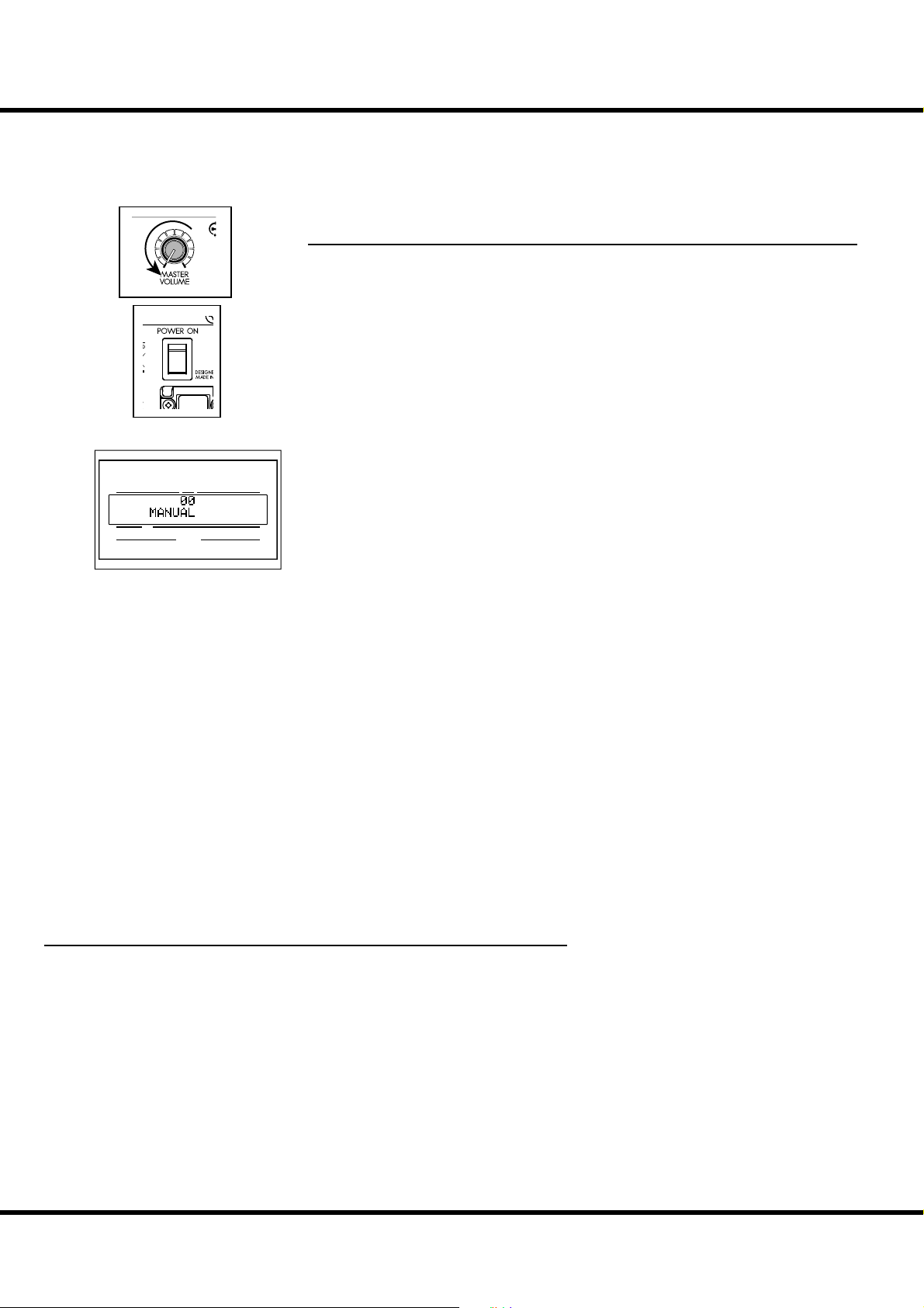
1. Before turning the power ON, con rm the [MASTER VOLUME] knob is set to
minimum.
2. Turn the [POWER] (on the rear of SKX) to the “ON”. e Title mode and then the
Play mode are displayed (as illustrated).
NOTE: For protecting the circuits, the SKX is designed not to play immediately at the power on
(about 6 seconds).
3. Turn the power to the connected ampli er etc. “ON”.
4. Play a bit, raising the [MASTER VOLUME] knob to adjust the volume to your
needs.
NOTE: The [MANUAL] button does not sound in the default settings. Pull out the Drawbars or
select any of the FAVORITE [1] to [10] buttons to get sound.
5. Adjust the volume of ampli er etc.
NOTE: To turn “OFF” the power, do the above steps in reverse. (Turn “OFF” the ampli er etc. rst.)
NUMBER NAME
PATC H
BACK UP
e SKX “remembers” the unit’s status immediately before the power is turned o ,
returning the unit to that status upon the next power-on.
e status of the default settings are the same as when the Favorite button [1] is
depressed.
AUTO POWER OFF
e SKX has an “AUTO POWER OFF” feature which will automatically turn the
power on the SKX “OFF” if no keys or buttons are pressed for 30 minutes.
To enable or disable the AUTO POWER OFF function, see “SYSTEM” P. 102.
NOTE: Depending on the status of SKX, while editing, for example, the power may not
turn o , even if the set time of AUTO POWER OFF elapses. So make sure to turn the
“POWER” switch OFF manually, after every use.
RESET TO THE FACTORY SETTINGS
To reset all parameters of SKX to its default settings, do the following:
OPERATION PROCEDURES
1. Switch the [POWER] of SKX o .
2. Holding down the [RECORD] button, switch the [POWER] ON.
3. Keep holding down the button until “Loading Default...” is displayed.
4. When the Play mode is displayed, this operation is completed.
Skx
Owner’s Manual
Page 23
PLAY WITH THE PATCHES
ere are 100 Patches loaded in memory from the factory, allowing you to immediately
start playing. You can also create 100 Patches of your own.
“USER” AND “ PRESET”
Patches
First
refer
refer
refer
U001
U002
U003
U004
U005
P098
P099
P100
Second
ird
Fourth
Fih
Mezzo Forte
Forte
Fotissimo
Manual
“FAVORITE”
buttons
23
1
MANUAL
exclusive
“VALUE”
knob
in PLAY mode
sequential
select
“P” are not rewritable
23
There are two domains: “USER” and “PRESET” in SKX’s
Patch memory. You can freely overwrite in the “USER” domain, but you can not do so in the “PRESET” domain as it
contains the factory settings.
“USER” and “PRESET” are indicated by “U” and “P” respectively.
HOW TO CALL A PATCH
Example: Select U041.
2
PLAYER
1
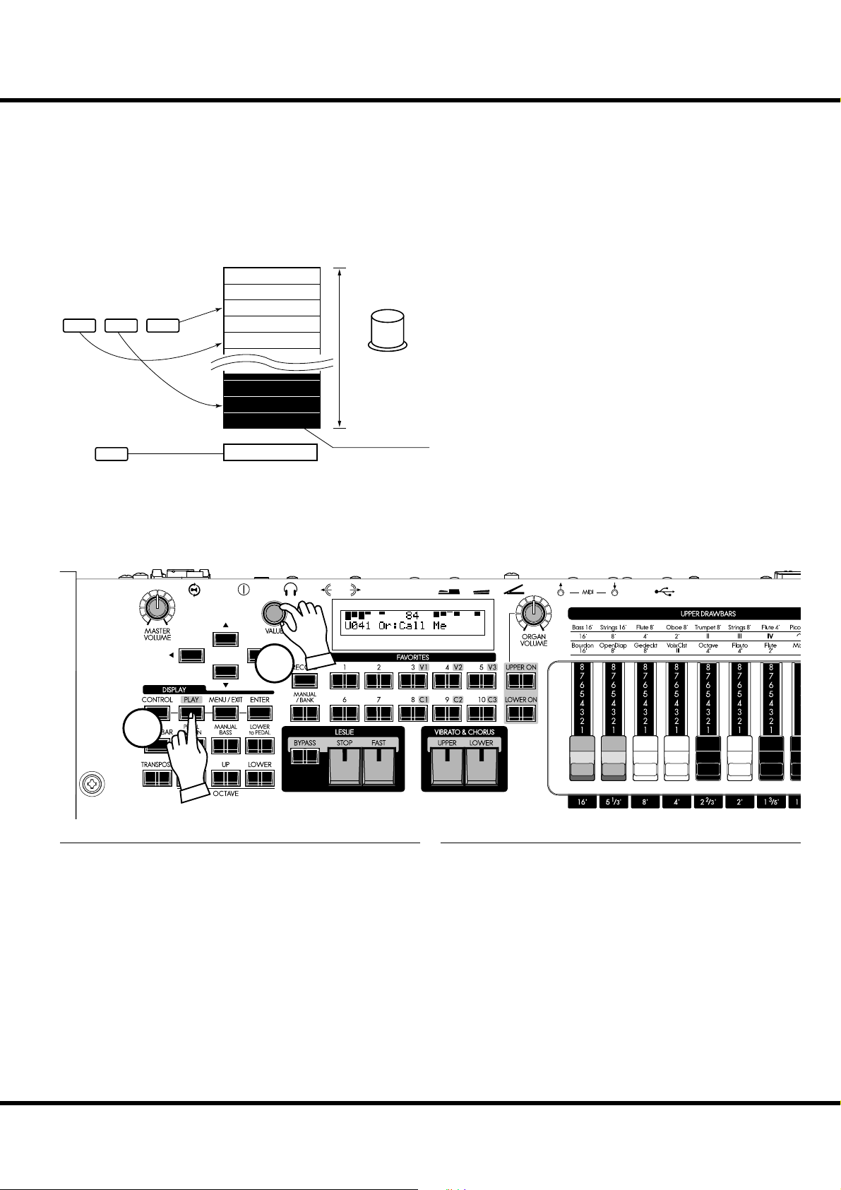
① GO TO THE PLAY MODE
Select the PLAY button, to enter PLAY mode.
② SELECT THE PATCH NUMBER
Select the Patch number U041 with the [VALUE] knob. Read
the [PRESET PATCH LIST] (P. 138) in the Appendix for the
Preset Patch details.
Call various Patches to play. When you call Patches, not only
the Drawbar registrations but the e ects such as Leslie, reverb ,
and Extra Voices also change.
NOTE: You can set the types of parameters to call (P. 74 #2 to 10).
NOTE: You can set the FAVORITE buttons to select a Patch with direct
key-in (P. 74 #11)
Getting Ready To Play
Page 24
24
REGISTER FAVORITE PATCHES ( FAVORITES)
Patches are selected with the [VALUE] knob. On stage, it is convenient to have your favorite Patches available immediately. Here’s how:
Register PATCHES to FAVORITES
Ex. Register U041 to “3-2”
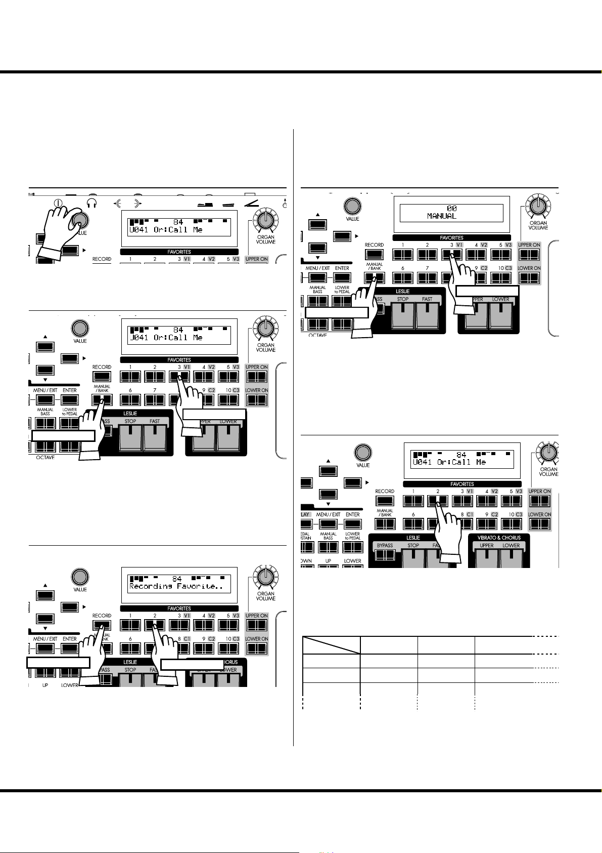
① SELECT THE PATCH
Select the Patch you want to register (in this example, U041) to
a favorite button as shown on the previous page.
② SELECT THE BANK TO REGISTER
Press
With holding
How to recall FAVORITES
Ex. Call the “3-2”
① SELECT THE BANK
Press
With holding
Press and hold the [MANUAL/BANK] button and select one
of the numbered Favorite buttons corresponds to “BANK” (for
this example, [3]).
NOTE: The Favorite button displays the Bank while the [MANUAL/
BANK] button is holding.
NOTE: It is not necessary if you do not change the Bank.
② SELECT THE NUMBER
Press the Favorite button corresponds to “ BANK” (in this example, [3]) with holding the [MANUAL/BANK] button.
NOTE: The Favorite button displays the Bank while the [MANUAL/
BANK] button is held down.
NOTE: It is not necessary if you do not change the Bank.
③ SELECT THE NUMBER TO REGISTER
With holding
Finally, press the desired Favorite button corresponds to
“NUMBER” (in this example, [2]), holding down the [RECORD] button.
e display will show “Recording Favorite..” for
approximately ½ second, and the selected Favorite button will
blinks momentarily. Your Favorite is stored.
Press
Press the Favorite button “NUMBER” (in this example, 2) you
wish to recall. e Favorite button lights and the corresponding
Patch is called.
BANK and NUMBER
Number
Bank
1
2
3
e “BANK” and “NUMBER” are method of managing number of Favorites e cient. ey are used to be registered like the
above chart according to song or show advance.
1
U011 Born Verse U012 Born Solo U011 Born Verse
U024 MyLife Pf U045 Lucy Org U023 GetBack EP
P061 Classic P062 Slow P063 Contemp.
23
Skx
Owner’s Manual
Page 25
Column: RECORD FAVORITES LIKE PRESET BUTTONS
You can record a Favorite Patch with a procedure similar to the Hammond XB/XK
series organs, by holding the [RECORD] button, and pressing the selected favorite
button - after doing the following procedure.
25
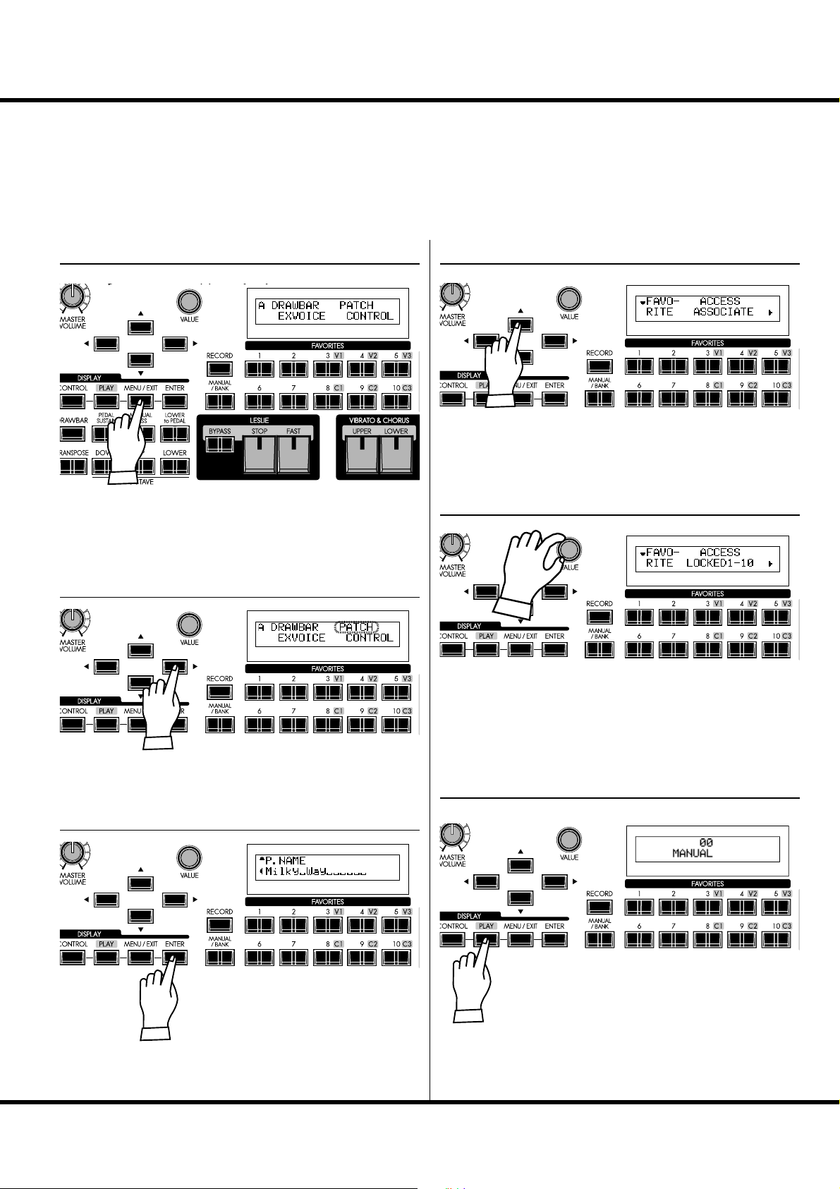
① LOCATE THE MENU MODE
Press the [MENU/EXIT] button. e Menu mode appears.
Repeat-press the menu button until the “A” menu appears (if
necessary).
② SELECT THE PATCH
④ GO TO THE FAVORITE PAGE
Press the [] button twice. e Favorite page appears.
⑤ SET VALUE TO LOCKED1-10
③ ENTER
Press the [
PATCH option (it will blink).
Press the [ENTER] button to select the
Patch Function mode.
] buttons to select the
Turn the [VALUE] knob and set the value of the item ACCESS
to “LOCKED1-10”.
⑥ RETURN TO THE PLAY MODE
Press the [PLAY] button to Return to the
Play mode.
Getting Ready To Play
Page 26
26
USE THE FOOT CONTROLLERS
Expression and sustain are important elements in any performance. Here you’ll learn how
to connect these controllers.
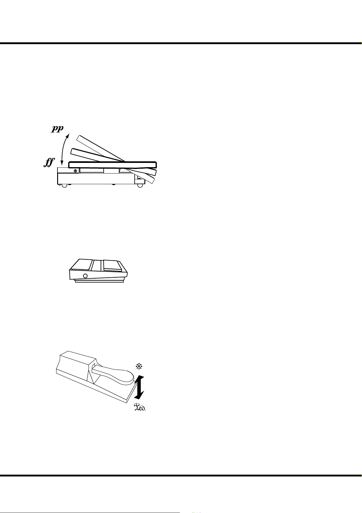
EXPRESSION PEDAL
EXP-50J (optional)
e Expression Pedal controls the overall volume or loudness of
the SKX. Press forward with the front of your foot to increase the
volume and back with your heel to decrease the volume.
NOTE: The performance of the Expression pedal can be tailored in vari-
ous ways. (P. 77)
NOTE: You can control whether or not you want the Extra Voice sections
to receive Expression. (P. 75)
FOOT SWITCH
FS-9H (optional)
DAMPER PEDAL
e Foot Switch can be programmed to various functions. e
default setting is [LESLIE S/F ALTERNATE]. Every press toggles,
the speed of the Leslie e ect to fast or not.
NOTE: For information about how to set the Foot Switch function as-
signment. (P. 76)
The Damper Pedal holds the played notes as same as acoustic
piano.
You can hold the notes during change the chord without interrupt
sound.
NOTE: You can change the part assignment of the Damper Pedal. (P. 76)
VFP1 (optional)
Skx
Owner’s Manual
Page 27
TRY CREATING YOUR OWN SOUND
In this section you’ll learn how to create your own sound. In this example, the Organ and
Extra Voices are combined (Jazz Organ and Electric Piano).
SELECT [ MANUAL]
First, select the [MANUAL] button (LED lit).
e [MANUAL] button makes all the current top panel set-
tings active, allowing for real-time registration, and the creation
of new Patches.
NOTE: To return to the Patch, press the [MANUAL] button again (LED
o ).
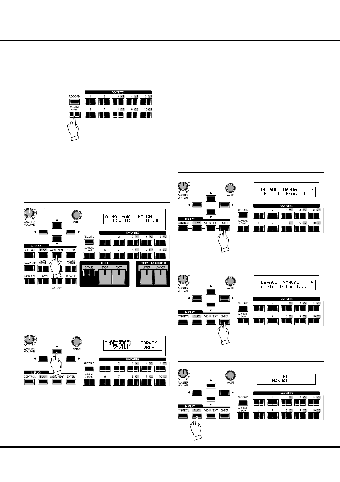
Column: INITIALIZE THE INTERNAL SETTINGS [MANUAL]
27
When the [MANUAL] button is “ON”, some parameters
which does not on the panel (e.g. Organ Type) may set at
undesired value. is is the procedure to return them to the
DEFAULT status.
① GO TO THE MENU MODE
Press the [MENU/EXIT] button. e Menu mode appears.
If the display is di erent from the above illustration, select the
[MENU/EXIT] button again.
② LOCATE PAGE E
③ ENTER
Press the [ENTER] button. is brings
up the MANUAL page of the DEFAULT
Function mode.
④ ENTER AGAIN
Press the [ENTER] button. e contents
of MANUAL are initialized.
Press the [] button 4 times reaching Page E. e DEFAULT
entry is blinking.
⑤ RETURN TO THE PLAY MODE
Press the [PLAY] button to return to the Play mode.
Getting Ready To Play
Page 28

TRY CREATING YOUR OWN SOUND - continued
28
SWITCH THE ORGAN SECTION ON
PULL OUT DRAWBARS
In this example, make sounds to begin with the Organ Section.
e ON buttons switches sounds or does not at each part for
the Organ Section.
NOTE: What is a “PART”? (P. 32)
Switch the [UPPER ON] button “ON”. e UPPER part of
the Organ Section will sound.
NOTE: You can set that the Extra Voice Section turns o automati-
cally by the Organ Section is switched on. (P. 79)
Next, set the [ORGAN VOLUME] knob. It adjusts the overall
volume for the Organ Section. Set this knob in the center position at this time.
Pull out Upper Drawbars to your taste. You can monitor your
selections easily while playing the keyboard.
e Drawbars make the fundamental organ sound of SKX. e
tone changes depending on how far the Drawbars are pulled
out.
e volume of each sound becomes maximum when the Drawbar is fully pulled out, and null when fully pushed back. e
drawbars are arranged so that the pitch grows higher from left
to right.
For this example, pull the rst three Drawbars out all the way as
shown in the illustrated on the left 16´, 5 ⅓ ´ and 8´.
NOTE: You can change the sound character of the Drawbars. (P. 72)
NOTE: The present registration is displayed in the Play mode. (P. 63)
ADD THE TOUCH-RESPONSE PERCUSSION
Hammond’s Touch-Response Percussion adds a distinctive attack to the Tone Wheel/Drawbar tones. is Percussion is not
like a drum or cymbal, but closer to an xylophone or marimba.
[PERCUSSION] is available only on the UPPER part.
To enable the Percussion, turn the [ON] button “ON”.
e [SOFT] button reduces the volume of the Percussion voice
and [FAST] button quickens the decay of the Percussion voice.
ere are two choices of pitch for Percussion. One sounds an
octave above the note played (“Second”), and another sounds
a “twelfth” above. (“ ird”) - When the [THIRD] light is o
“Second” is selected.
For this example turn all of the Percussion buttons “ON”
([ON], [SOFT], [FAST], [THIRD]).
NOTE: You can ne-tune the Percussion parameters to your taste. (P.
80)
Skx
Owner’s Manual
Page 29
ADD EFFECTS TO THE ORGAN SECTION
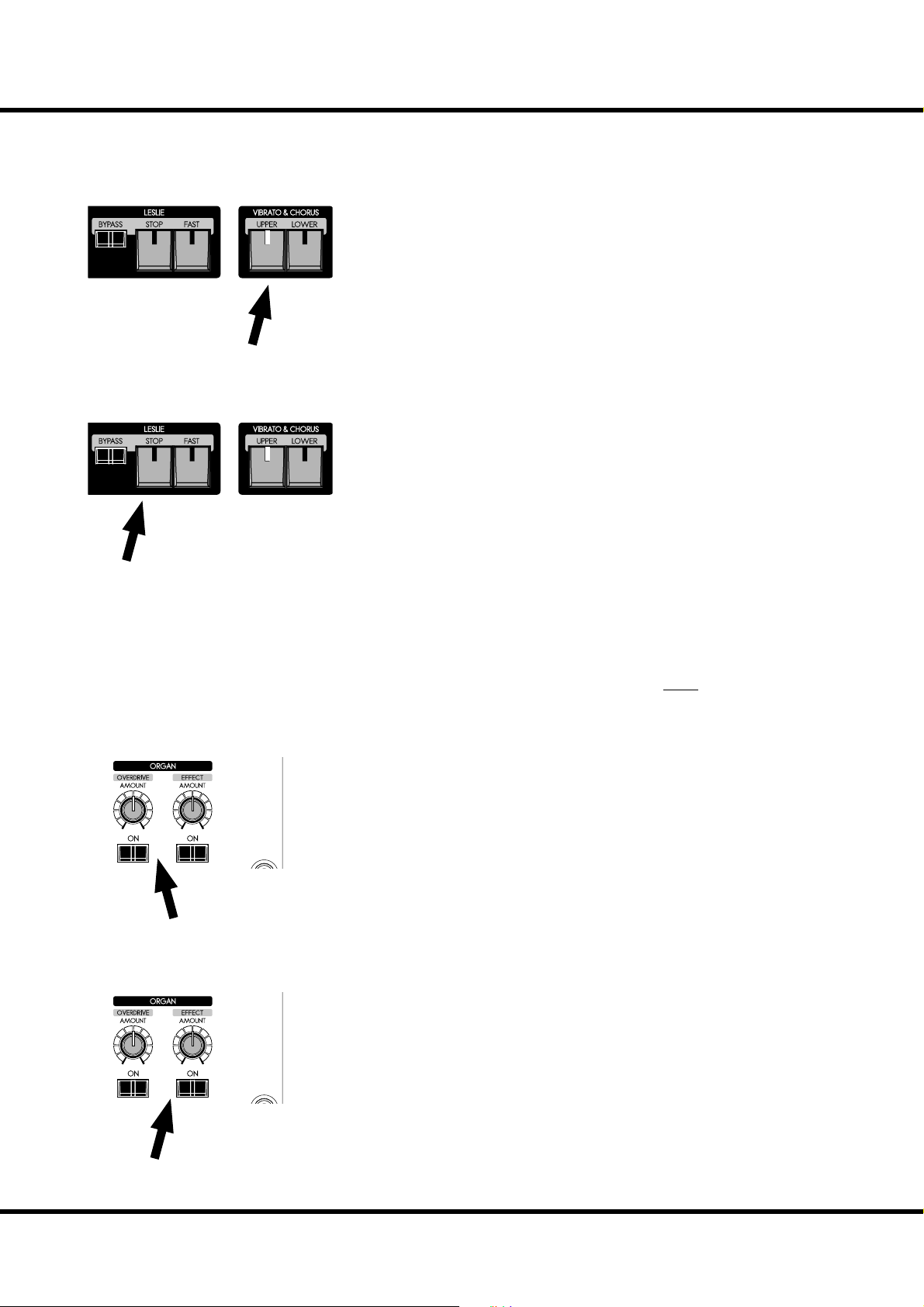
VIBRATO & CHORUS
Adding a richness to the sound by changing pitch slightly with periodically.
[UPPER], [LOWER] buttons
Switches the Vibrato & Chorus e ect ON/OFF. When “ON” the light illuminates.
NOTE: You can adjust the Vibrato & Chorus e ect to your liking. (P. 81)
For this example, switch ON the [UPPER] button.
LESLIE
e LESLIE e ect is the famous “Moving and Swirling” sound provided by rotating
horns and speakers, but executed here in the Digital realm.
[FAST] button
is button toggles the mode of the Rotor to fast or not. When the light is “ON”, it
is FAST, and when “OFF”, not.
[STOP] button
is button sets the mode when the [FAST] button is o . When the light is “ON”, it
is STOP, and when “OFF”, it is SLOW.
[BYPASS] button
To engage the Leslie e ect, press the [BYPASS] button turning the light “OFF”.
NOTE: These controls perform the same functions when a Physical Leslie is connected via the
11 pin socket.
NOTE: You can ne-tune the parameters of the Digital Leslie e ect etc. (P. 82)
For this example, let’s set the status of all lights “OFF”.
29
OVERDRIVE
MULTI-EFFECTS
e Overdrive section adds warmth at low settings, and “grit” or distortion at higher.
[ON] button
Toggles the Overdrive “OFF” and “ON” (when on the light is illuminated).
[AMOUNT] knob
Adjusts the amount of Overdrive. e amount increases as you rotate the knob clockwise.
In this example, the Overdrive is not used. e Button light should be “OFF”.
Adjusts the amount of the selected Multi-e ect to be applied to the Organ section.
e default settings: at “Tremolo”.
[ON] button
Toggles the Multi-E ects “OFF” and “ON” (when on the light is illuminated).
[AMOUNT] knob
Adjusts the amount of Multi-E ect to be applied. e amount increases as you rotate
the knob clockwise.
In this example, the Multi-E ects are not used. e Button light should be “OFF”.
Getting Ready To Play
Page 30
TRY CREATING YOUR OWN SOUND - continued
30
ALLOCATING THE EXTRA VOICES
Choose which parts will play the Extra Voices.
[UPPER ON] button
e Extra Voices play on the UPPER part.
MIX
BALANCE
EXV1 EXV2
[LOWER ON] button
e Extra Voices play on the LOWER part.
ere are two Extra Voice sections. You can assign these either for Upper or Lower
parts.
For this example, switch the [UPPER ON] button for EXTRA VOICE 1 at “ON”.
NOTE: You can set that the Organ Voice Section turns “OFF” automatically by the Extra Voice
Section is switched “ON”. (P. 79)
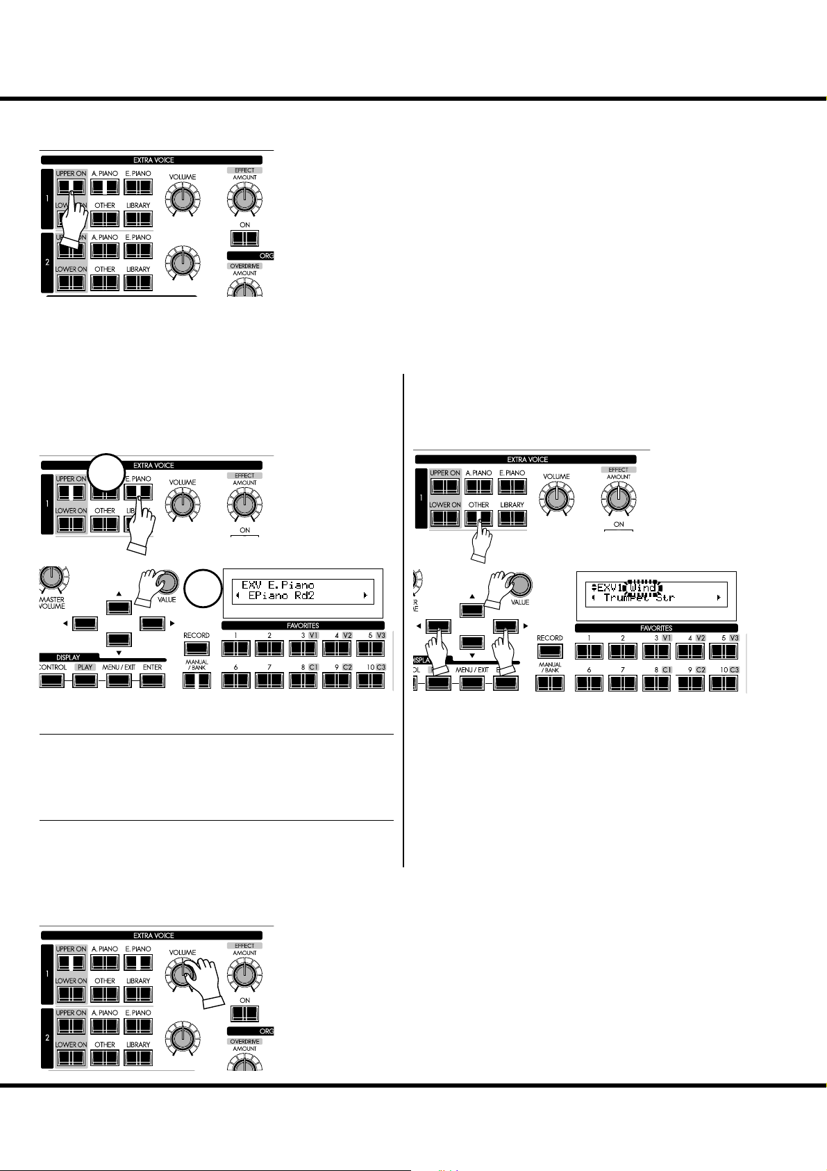
SELECT AN INSTRUMENT
To choose the Extra Voice instruments, press the desired Voice
Group button on the top panel, then select your speci c instrument in the display.
Select the “EPiano Rd2” as follows.
1
2
① SELECT A VOICE GROUP
Press the [E.PIANO] button.
An instrument what used previously in the selected voice group
will selected automatically.
② SELECT AN INSTRUMENT
Select “EPiano Rd2” with the [VALUE] knob.
Now the “EPiano Rd2” is ready to play.
Column: To select the other group (e.g.“Wind”)
e voice group “Wind” is hidden behind the [OTHER] button. To select this;
1
3
2
1. Press the [OTHER] button.
2. Locate the cursor at voice group with the [] button.
3. Select the “Wind” with the [VALUE] knob.
4. Locate the cursor at instrument with the [] button.
or, Press the [OTHER] button several times after step 1.
4
ADJUST THE VOLUME BALANCE
To achieve your desired blend of Organ and Extra Voice (In this example the E.
Piano), adjust the Extra Voice volume knob accordingly.
e [VOLUME] knob adjusts entire volume of the Extra Voice sections.
e [BALANCE] knob adjusts the volume balance between Extra Voice sections 1
and 2.
MIX
BALANCE
EXV1 EXV2
Skx
Owner’s Manual
Page 31

ADD EFFECTS TO THE EXTRA VOICE SECTION
MULTI-EFFECTS
e most suitable e ects for each Extra Voice are automatically
called when selecting that voice.
[ON] button
Adds e ects to the Extra Voices. When “ON” the light is il-
MIX
BALANCE
EXV1 EXV2
luminated.
[AMOUNT] knob
Adjusts the amount of e ect added. Turning the knob clockwise increases the amount.
ADD REVERB TO BOTH SECTIONS
REVERB
e SKX’s Digital Reverberation is common to both Organ
and Extra Voice sections.
[ON] button
Turns the Reverb e ect ON.
MIX
BALANCE
EXV1 EXV2
[DEPTH] knob
Adjusts the amount of Reverb added. Turning the knob clockwise increases the amount.
31
Getting Ready To Play
Page 32

TRY CREATING YOUR OWN SOUND - continued
32
WHAT IS A “ PART”?
Each “PART” is equivalent to a player in a band or an orchestra. e 3 Parts here are
expressed in Organ terms: UPPER. LOWER, and PEDAL. ese parts can be individually played with di erent sounds.
e SKX has 2 keyboards. All parts are available simultaneously, by expanding the MIDI
Pedalboard.
MANUAL BASS
You can play the PEDAL voices using the lowest notes of the
LOWER keyboard.
ER
Manual Bass
[MANUAL BASS] button
To use the Manual Bass function, press the [MANUAL BASS]
button and the light will go ON. e PEDAL/Bass sound is heard
in conjunction with the lowest note being played, on the manual
keyboard till that time.
In order to interface with the melody performance, the default
Manual Bass upper limit point is set to sound up to, and including
middle “B”.
NOTE: The Manual Bass can be set to play in Lowest, Polyphonic, and
Chord (P. 110). You can change the playing range of the Manual Bass
(the upper limit) (P. 110).
e part obtained when the Manual Bass is selected is called PEDAL part and its sound is controlled by the Drawbars ([PEDAL]
when selected in Drawbar Select). is is originated from the style
of playing bass on the pedal keyboard of a 3 keyboard type organ.
You can use both the manual bass and the split at the same time.
is makes it possible to play the bass + chord + melody only by
yourself.
NOTE: You can triggering the Manual Bass by foot switch (P. 76).
Upper
or, Swell
Lower
or, Great
Pedal
Skx
Owner’s Manual
Page 33
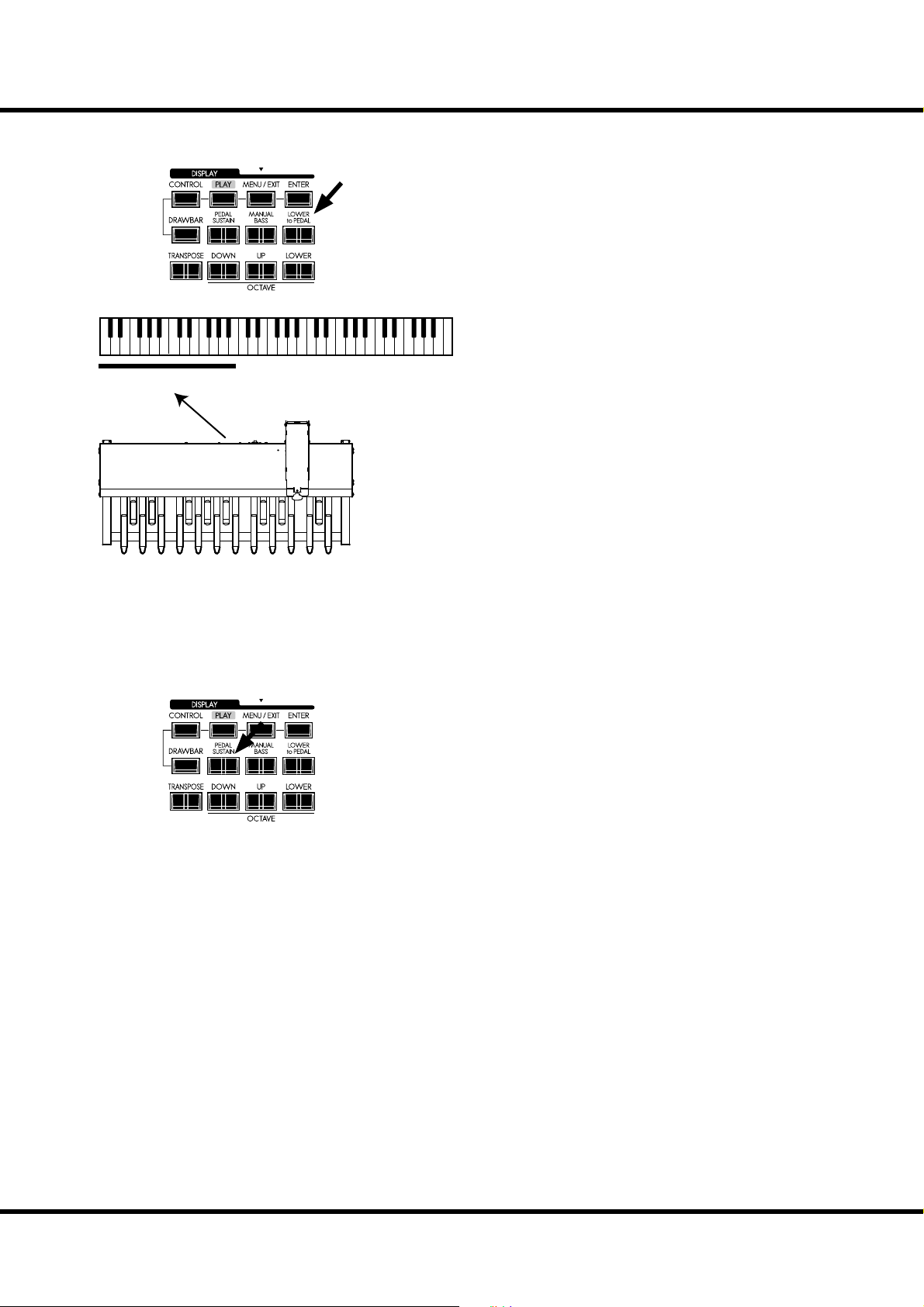
LOWER TO PEDAL
ER
Lower to Pedal
33
When a MIDI Pedalboard is connected to the SKX, you can play
the LOWER part sound (or “registration”) with the Pedalboard using the “LOWER TO PEDAL”.
[LOWER to PEDAL] BUTTON
Turns the Lower To Pedal function “ON” (LED lit) and “OFF”
(LED not lit).
e default upper limit for Lower to Pedal is below Middle “B”.
NOTE: You can change the playing range (the upper limit) of the ‘Lower
to Pedal’. (P. 110 )
PEDAL SUSTAIN
ER
When the [PEDAL SUSTAIN] button is “ON”, the PEDAL tones
will smoothly decay upon release, much in the manner of a string
bass. is is a popular option for playing the PEDAL tones.
[PEDAL SUSTAIN]
Turns Pedal Sustain “ON” (LED lit) and “OFF” (LED not lit).
After releasing your foot from a Pedal note (or releasing your nger
from the LOWER key when you are using Manual Bass, the sound
will slowly fade, or decay.
NOTE: You can adjust the Pedal Sustain. (P. 73 )
Getting Ready To Play
Page 34

TRY CREATING YOUR OWN SOUND - continued
34
RECORD THE PATCH TO MEMORY
All the previous settings can be recorded to any Patch within the range of U001 to U100.
Example: RECORD TO U032
① PRESS THE [RECORD] BUTTON
Press the [RECORD] button.
A prompt will appear in the display allowing you to select the
Patch you want to record.
② SELECT THE PATCH TO RECORD
③ PRESS THE [ENTER] TO DECIDE
Select the Patch number, this time U032, to record, using the
[VALUE] knob or type the buttons such as [3] [2].
Press the [ENTER] button.
e Patch Number is decided and the display will show, “Re-
cording Patch” for approximately ½ second, after which
the previous mode will return.
e recorded Patch is automatically selected.
NOTE: The user created Patch data is not lost when the power is
turned o and/or disconnected.
Skx
Owner’s Manual
Page 35

35
SETTING UP
Page 36
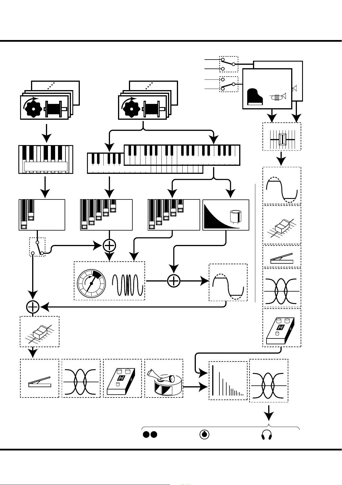
36
Pedal
Virtual
Tone Wheel Set
Pedalboard
SOUND ENGINE STRUCTURE
from keyboards
Lower&Upper
Virtual
Tone Wheel Set
Upper Keyboard
Lower Keyboard
Upper
Lower
Upper
Lower
Allocate
Extra Voice
Extra Voice
Generator #2
Generator #1
EXV Balance
12
Overdrive
Pedal
Drawbars
Pedal
V&C
Organ Volume
Expression
Vibrato & Chorus
TC & Equalizer
Lower
Drawbars
Multi Effect
Drawbars
Leslie
Simulator
Upper
Percussion
Overdrive
Reverb
EXV Volume
Expression
Equalizer
Multi Effect
Master
Equalizer
Skx
Owner’s Manual
Line Out,
Leslie 11Pin,
without Leslie simulator
Phones
Page 37

To fully utilizing SKX, read the following detailed explanations about the various functions
for creating music.
ORGAN SECTION
TONE-WHEELS
e sound source or “engine” of the classic Hammond Organ are the electro-magnetic
Tone Wheel Generators. On the SKX, the Tone Wheel engine is replicated digitally.
While the power is on, each of the 96 virtual Tone Wheels keeps oscillating as they did
in the vintage Hammond Organs.
KEYS
e tone signals created with the 96 virtual Tone Wheels are “switched” at the keys.
To each key the signals corresponding to the pitch and harmonics (for example, 9 sets on
the manual keyboard) are distributed, and when you touch or release a key, the switch
connects or cuts the tone signals.
DRAWBARS
Each Drawbar represents a fundamental harmonic. Each bar adjusts the value of each
harmonic. ere are 9 drawbars corresponding to 9 di erent harmonics.
TOUCH-RESPONSE PERCUSSION
e Percussion creates a decaying sound on the UPPER manual.
VIBRATO & CHORUS
e Vibrato & Chorus gives depth and richness to the organ sound by slightly varying
the pitch (Vibrato), or doubling the voice by mixing the original sound, with a duplicate,
slightly detuned one (Chorus).
37
TONE-WHEEL SETS
The Tone Wheel Sets are divided into the
Manuals and the Pedal Part. This is to give the
Pedal Part the Decay (= the sound gradually
fading out while pressing the key) or Sustain
E ect. (= the sound gradually fading out after
the key is released).
HARMONICS
Harmonic is a pitch of a di erent ratio to a certain pitch; for example, the one octave higher
C to the middle C. The more Harmonics, the
brighter and richer sound is obtained.
OVERDRIVE
e Overdrive creates distortion as if an ampli er was being driven beyond its limits.
MULTI-EFFECTS
e Multi-E ects create various e ects such as tremolo and Wah.
EQUALIZER, LESLIE, REVERB
e built-in E ects are as follows: an Equalizer for sculpting the tonal response, a Leslie
E ect for rotary speaker e ects, and Reverb.
( e built-in Leslie E ect is disengaged when a physical Leslie is connected to the 11-pin
terminal.)
EXTRA VOICE SECTION
SOUND ENGINE
e Extra Voice section is the sound engine for playing piano and other musical instruments. It is independent of the Organ Section.
EFFECTS
You can add Overdrive, Multi-E ects, Equalizer and Reverb to the Extra Voice Section.
MASTER EQUALIZER
e combined signal of Organ and Extra Voice is routed through the Master Equalizer.
Allowing you to tailor your sound for the provided venue, amp, sound system or recording. e settings are not saved in Patch memory.
Setting Up
Page 38

38
ORGAN SECTION
ORGAN TYPE
ere are various “Organ” types: the Hammond Tone Wheel organs used in everywhere rock, jazz, and Gospel, the transistor organ frequently heard in pop music of
1960’s. Classical pipe organ used in classical music or church services. All organs have
characteristic sounds.
e SKX will sound like the types of organ you choose.
TONE-WHEELS (BType1, BType2, Mellow)
These are various types of Hammond Organs’ characteristic Tone Wheels. The
Hammond Organ’s original purpose was to duplicate the pipe organ, however, they
became famous for producing a unique sound of their own.
e BType1 and BType2 have the B-3/C-3’s traditional Tone Wheel sounds. e
BType2 has more wow- utter and leakage noise.
e Mellow is not a Tone Wheel, if strictly speaking. It replicates the rst-generation
non-mechanical Transistor Hammond Tone Generators like the GT-7 and Concord.
TRANSISTOR ( Vx, Farf)
After the transistor became generally used, the light weight organs were introduced
(such as Ace Tone TOP-6 etc.) using the transistor circuit instead of the Tone Wheels
or tubes. e circuit system is di erent from maker to maker or model by model. We
have replicated 2 representative types here.
e Vx is a type to combine the triangle wave and square wave with several footages.
e Farf is one to combine the sound wave forms coming through plural lters with
the tablet switch.
PIPE
e pipe organ produces sounds by oscillating the air sent through the pipe. e
name of Stops tells you which wind instruments that you are duplication.
You can create other sounds by combining di erent organ Stops, in the same way
Drawbars are used on the SKX.
Skx
Owner’s Manual
Page 39

Column: SELECTING THE ORGAN TYPES
Use the control panel for switching the Organ Types.
Example: Switching the Organ Type to “Pipe”
① PRESS THE [DRAWBAR]
Press the [DRAWBAR] button. The DRAWBAR Function
mode is displayed and the presently selected Organ Type
(“BType1” etc.) of the manual keyboard will blink.
39
② SELECT THE ORGAN TYPE
③ RETURN TO THE PLAY MODE
Select “Pipe” with the [VALUE] knob. e pipe organ sounds
when you play the notes from the Organ section.
NOTE: Though this page is for Lower and Upper part, the Organ Type
“Pipe” switches Pedal part also from other types to “Pipe”
type.
To return to the Play mode, press the [PLAY] button.
Setting Up
Page 40
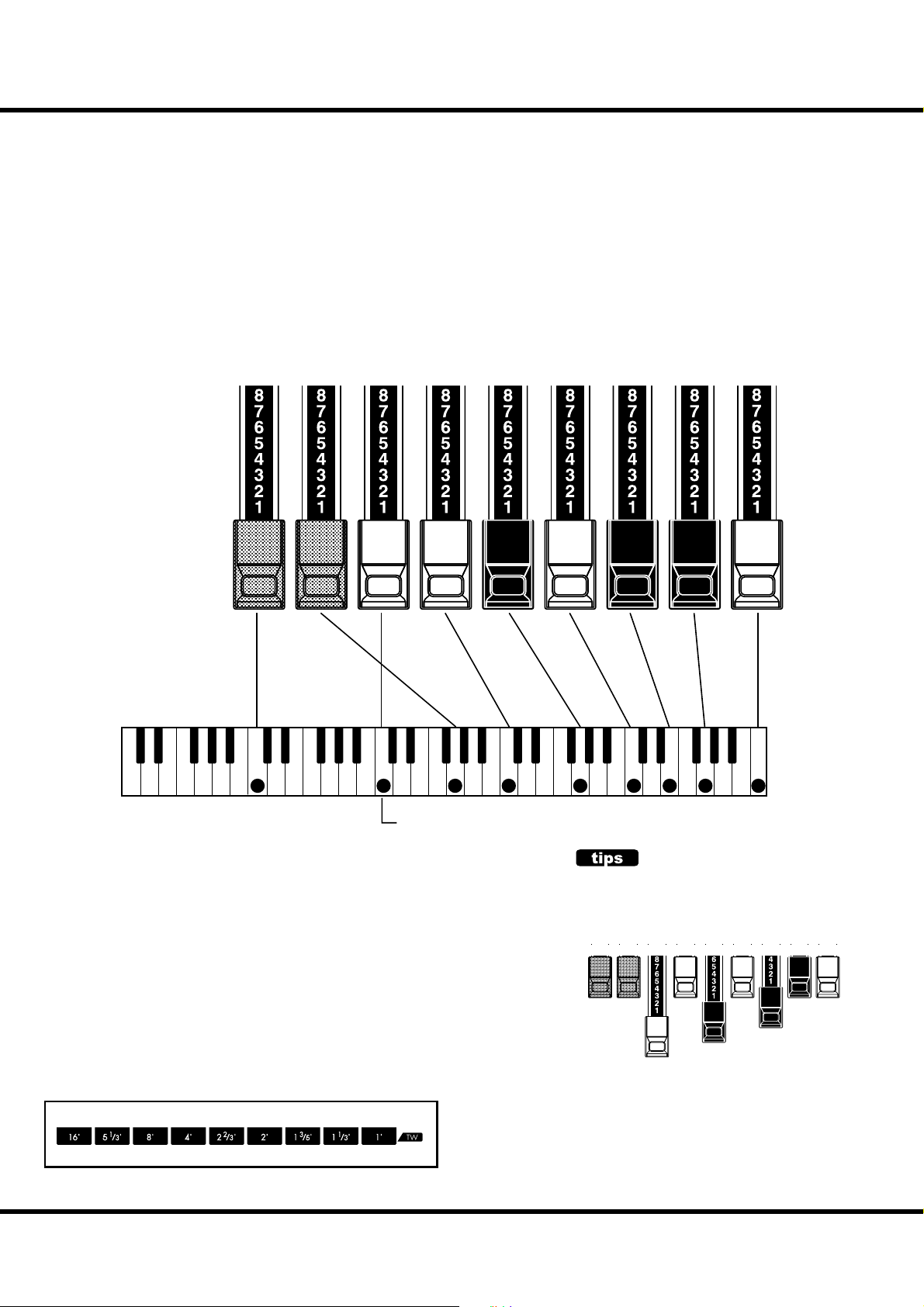
40
HARMONIC DRAWBARS™
e 9 Drawbars on the SKX are used to create the basic “Hammond” sounds. Each
Drawbar is marked with the register numbers 1 - 8 along the at part of the Drawbar.
If you push back a Drawbar until you cannot see any number at all, the sound of
the Drawbar is not heard. If you pull it out to the fullest position the sound level is
maximum.
When recalling a Patch, the drawbars’ “positions” will change internally, but not
physically. However, if you move a drawbar, the setting will “snap” to that drawbars
current position. e [MANUAL] or [PRIO] keeps matched Drawbar registration.
DRAWBARS (ON TONE-WHEEL: BType1, BType2, Mellow)
Harmonic:
Footage:
Sub
Fund.
16'
Sub
3
51/3'
Funda-
mental
8' 4'
2 3 4 5 6 8
2
/3'
2
2'
13/5'11/3'
1'
Middle “C”
e pitch of each Drawbar is as shown above, when the middle C is depressed. e
footage marked (´) on the handle end of each Drawbar is derived from the corresponding length of pipes of a pipe organ.
e numbers 1 - 8 on the “bar” portion of each Drawbar indicate the volume of the
sound to be produced as well as the guide to remember Drawbar settings.
Pull the fundamental (8´), the third harmonic (2⅔ ´) plus the fth harmonic (1´)
Drawbars out completely and play the keyboard. Notice how the sound resembles
a clarinet.
If you push the 8´ Drawbar half-way, you’ll notice the sound becomes more highpitched and a bit “harder”. Now pull the 8´ Drawbar back out fully and push the
2⅔ ´ and 1´ in halfway. Notice how the sound becomes mellower.
Experiment with the Drawbars to obtain your own personal favorite sounds.
In the case of the Tone Wheel Organ, refer the correspondence
between each bar and the footage to the “TW” row in front of
the Drawbars.
Skx
Owner’s Manual
DRAWBAR REGISTRATION
The lengths of the pulled out Drawbars.
16' 8' 4'
51/3'
Example of “Clarinet”
22/3'
2'
13/5'11/3'
1'
Page 41

DRAWBARS FOR THE UPPER AND LOWER PARTS
e Colors of the Drawbars are traditional to Hammond, and were established to
provide a quick visual guide to the harmonics generated by the Drawbars.
WHITE DRAWBARS
16' 8' 4'
51/3'
BLACK DRAWBARS
16' 8' 4'
51/3'
22/3'
22/3'
2'
2'
13/5'11/3'
13/5'11/3'
1'
e left white Drawbar represents the “fundamental” or “8´
base” tone. All of the other white Drawbars are octave intervals
or harmonics of the fundamental tone. e tonal brilliance is
greatly increased by adding white Drawbars, but the harmonics
added are always in “consonance” or harmony.
1'
e black Drawbars represent the “dissonant” harmonics which
are also necessary in building rich tone colors. e mellowness
of a horn, the pungency of strings, and the brilliance of reed
voices owe much of their character to the presence of these
harmonics in di erent degrees.
41
BROWN DRAWBARS
16' 8' 4'
51/3'
22/3'
2'
13/5'11/3'
1'
DRAWBARS TO USE ON THE PEDAL
16'
8'
e two brown Drawbars on the far left give depth and richness
to the sound. e left 16´ is one octave lower than the 8´, and
5⅓ ´ is the third harmonic of the 16´ fundamental. Normally,
the tones are built on the 8’ fundamental, but, if you want to
add depth to the tone or to expand the playing range by one
octave lower, build your tones on the 16´ fundamental.
e two brown Drawbars located between the Drawbars for
the Upper and Lower parts control the sounds produced by the
Pedal part. e left Pedal Drawbar produces a composite tone
at 16´ pitch for a deep foundation bass, while the right Pedal
Drawbar produces a composite tone at 8´ pitch, or one octave
higher.
Setting Up
Page 42

HARMONIC DRAWBARS™ - continued
42
DRAWBAR REGISTRATION PATTERNS
Regardless of the size of a pipe organ or its number of stops, all of its voices are related to four basic families of tone. e four basic families - Flute, Reed, String and
Diapason - can be quickly set up on the Drawbars by relating a pattern or shape to
each family.
Flute family (2 step pattern) Diapason family (check mark pattern)
16' 8' 4'
51/3'
22/3'
2'
13/5'11/3'
16' 8' 4'
1'
51/3'
22/3'
2'
13/5'11/3'
1'
Accompaniment Flute 8´ I .............. 00 8460 000
Accompaniment Flute 8´ II ............. 00 3220 000
Accompaniment Flute 8´ III ........... 00 8600 000
Chorus of Flutes 16´ ....................... 80 8605 002
Orchestral Flute 8´ .......................... 00 3831 000
Piccolo 2´ ........................................ 00 0006 003
Stopped Flute 8´ .............................00 5020 000
Tibia 8´ ........................................... 00 7030 000
Tibia 4´ ........................................... 00 0700 030
Tibia ( eater) 16´ .......................... 80 8605 004
Wooden Open Flute 8´ ................... 00 8840 000
Accomp. Diapason 8´ ...................... 00 8874 210
Chorus Diapason 8´ ........................ 00 8686 310
Diapason 8´ ....................................00 7785 321
Echo Diapason 8´ ........................... 00 4434 210
Harmonic Diapason 16´ .................85 8524 100
Harmonic Diapason 8´ ...................00 8877 760
Harmonic Diapason 4´ ...................00 0606 045
Horn Diapason 8´ ........................... 00 8887 480
Open Diapason 8´ .......................... 01 8866 430
Solo Diapason ................................. 01 8855 331
Wood Diapason 8´ .......................... 00 7754 321
Reed family (triangle pattern) String family (bow pattern)
2
16' 8' 4'
51/3'
22/3'
2'
13/5'11/3'
Bassoon 16´ .................................... 44 7000 000
Clarinet 8´ ...................................... 00 6070 540
English Horn 8´ .............................. 00 3682 210
Flugel Horn 8´ ................................ 00 5777 530
French Horn ................................... 00 7654 321
Kinura 8´ ........................................ 00 0172 786
Oboe 8´ .......................................... 00 4764 210
Trombone 8´ ................................... 01 8777 530
Trumpet 8´...................................... 00 6788 650
Tuba Sonora 8´ ............................... 02 7788 640
Vox Humana 8´ ..............................00 4720 123
16' 8' 4'
1'
51/3'
Cello 8´ ........................................... 00 3564 534
Dulciana 8´ ..................................... 00 7770 000
Gamba 8´ I ..................................... 00 3484 443
Gemshorn 8´ ................................... 00 4741 321
Orchestral String 8´......................... 00 1464 321
Salicional 8´ .................................... 00 2453 321
Solo Viola 8´ ................................... 00 2474 341
Solo Violin 8´.................................. 00 3654 324
Viola da Gamba 8´ .......................... 00 2465 432
Violina 4´ ........................................ 00 0103 064
Violone 16´ ..................................... 26 3431 000
/
2'
2
3'
13/5'11/3'
1'
Notice that Drawbar registrations are expressed in number groups of 2, 4 and 3. is
“2-4-3” number formula for Drawbar Registration has been a Hammond convention since the beginning. It has been found to be the easiest way to convey a speci c
setting. e rst two numbers correspond to the two brown Drawbars of either
manual. e middle four numbers designate the 8´, 4´, 2⅔ ´, 2´ Drawbars, and the
remaining three numbers refer to the last three Drawbars.
Skx
Owner’s Manual
Page 43

MODERN DRAWBAR REGISTRATIONS
e Drawbar registrations introduced on the previous page are typically for classical
music.
ey were created at the dawn of the Hammond Organ, when it was intended
to sound like a pipe or church organ. Later on, as the Hammond Organ spread
throughout Jazz, Pop, Rock and (especially) Gospel music, Some timeless registrations become common.
Jazz Bluesy
16' 8' 4'
51/3'
22/3'
2'
13/5'11/3'
ON SOFT FAST THIRD
All buttons at ON
1'
16' 8' 4'
51/3'
22/3'
2'
13/5'11/3'
43
1'
Groovy & Funky Max Power
16' 8' 4'
16' 8' 4'
51/3'
22/3'
2'
13/5'11/3'
1'
51/3'
Squabble
16' 8' 4'
51/3'
22/3'
2'
13/5'11/3'
1'
22/3'
2'
13/5'11/3'
1'
APPLICATION OF PERCUSSION
When Percussion is used, the sound of the 1´ Drawbar is cancelled. As it was on the Vintage B-3/C-3. A
trick is to keep the 1’ drawbar fully out, and then
turn the Percussion on and off as you play for a
instant change in sound. Try it!
Setting Up
Page 44
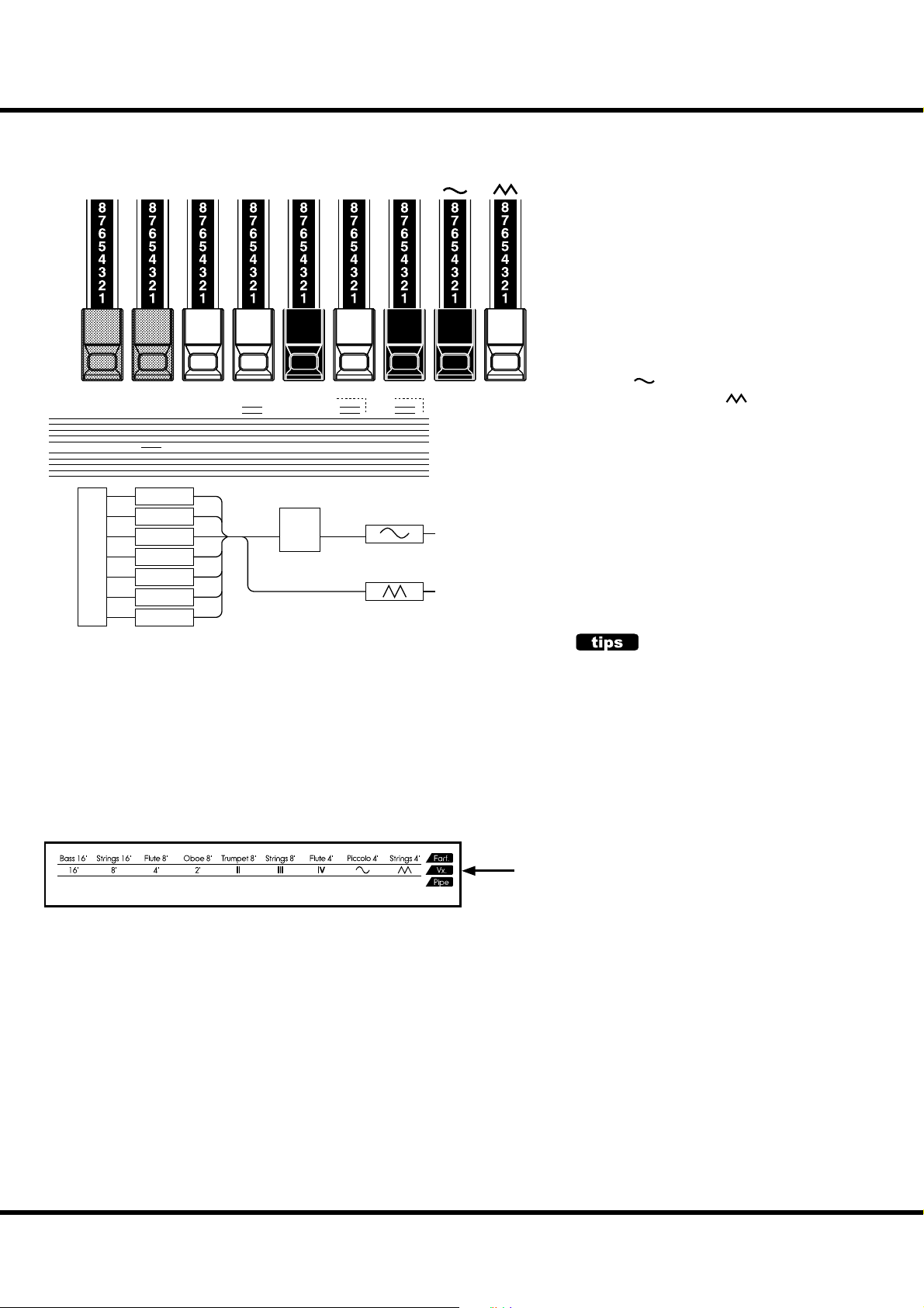
HARMONIC DRAWBARS™ - continued
44
DRAWBARS ( Vx)
16´ 4´ 2´
"
X
Oscillators
8´
X
16´
8´
4´
2´
II
III
IV
II
X
XXX
X
X
Filter
III
IV
e type of combo organ replicated by British “Vx” mode had Drawbar-type controls,
but they functioned di erently from Hammond Harmonic Drawbars Organ. e left
four Drawbars control individual pitches,
while the next three are “Mixture” Drawbars
which cause multiple pitches to sound. “II,”
“III” and “IV” refer to the number of pitches
represented by that Drawbar.
e right two Drawbars control the type of
tone produced by the rst seven Drawbars.
The “ ” Drawbar causes mellow tones
X
X
X
X
X
at Middle “C”
to output
to sound while the “ ” Drawbar causes
brighter and more harmonically complex
tones to sound.
NOTE: The left seven Drawbars WILL NOT sound
unless one or both of the right two Drawbars are also “out.” These two Drawbars
regulate the overall volume as well as
timbre of the total Drawbar registration,
and can be used separately or together.
Bourdon
OpenDiap8'Gedeckt8'VoixClst
16'
Octave4'Flute Dolce
II
Flute
4'
2'
Mixture
III
Hautbois
8'
If the Organ Type is set to Vx, refer to the “Vx” row on the other side of the Drawbars
for the correspondence between each bar and the footage.
FOOTAGE
“Footage” is a term inherited from the pipe organ.
It is used to designate the pitch at which a particu-
lar organ stop will sound. The number refers to the
length of pipe necessary to produce the lowest
note of that particular stop.
For example, if a stop is marked 8’ it means that
the lowest note on a standard 5-octave organ keyboard “C” will require a pipe 8 feet long.
Skx
Owner’s Manual
Page 45
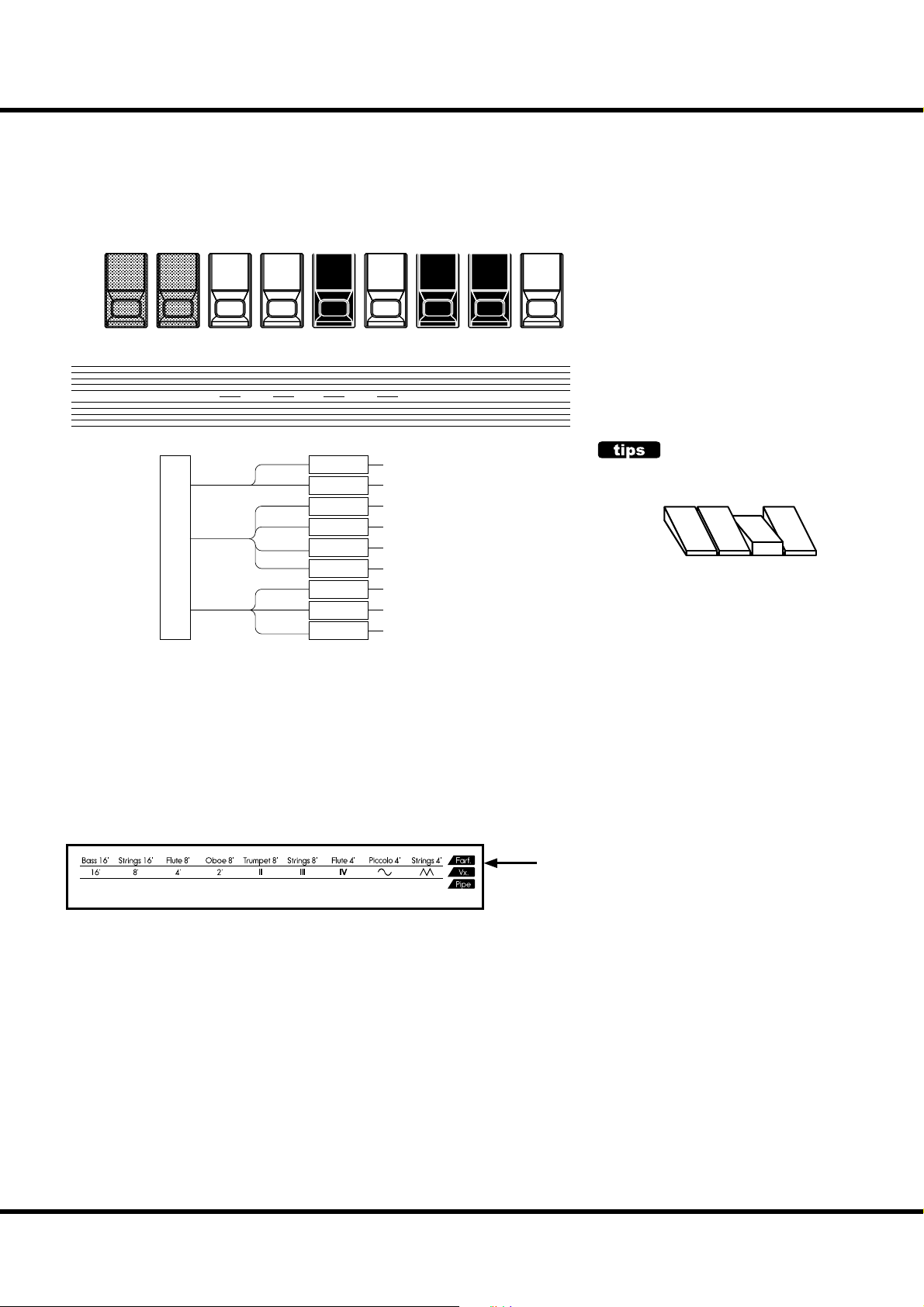
DRAWBARS ( Farf)
45
Bass 16´
"
Strings 16´
Flute 8´
XX
Oscillators
16
8
4
X
Trumpet 8´
Oboe 8´
X X X
Filters
Bass 16´
Strings 16´
Flute 8´
Oboe 8´
Trumpet 8´
Strings 8´
Flute 4´
Piccolo 4´
Strings 4´
Strings 8´
to output
Strings 4´
Piccolo 4´
Flute 4´
XXX
at Middle “C”
e original Italian “Farf” type organ was
tablet-equipped with different sounds at
various footages. On the SKX, the operation is made with Drawbars instead of tablets.
At the same footage, the tablets gives grow
brighter in sound as you progress to the
right. e names “Flute”, “Strings”, etc. are
general descriptions and do not re ect the
tonalities or characteristics of the real instruments.
TABLET
The “tablet” means a rocker-type tilt tablets of the
vintage organs.
Bourdon
OpenDiap8'Gedeckt8'VoixClst
16'
Octave4'Flute Dolce
II
Flute
4'
2'
Mixture
III
Hautbois
8'
When using the Farf Organ Type, refer to the “Farf” row on the other side of the
Drawbars for the correspondence between each bar and the footage.
Setting Up
Page 46

HARMONIC DRAWBARS™ - continued
46
DRAWBARS ( PIPE)
UPPER:
LOWER:
PEDAL:
Bourdon
16´
Principal
16´
Sub Bass 16´
+
Gedeckt 8´
Open
Diapason
8´
Principal
8´
Principal Chorus
Gedeckt
8´
Melodia
8´
+
Mixture IV
Viole
CelesteIIOctave
Flauto
Dolce4´Flute2´Mixture
4´
Rohr
Flute8´Prestant4´Flute
4´
When using the Pipe Organ Type, the stops are registered through the Drawbars,
and follow the classic organ layout left to right as follows: Flue, Mixture and Reed.
On the UPPER and LOWER parts, each Drawbar corresponds with a stop of the
pipe organ.
On the PEDAL part, two stops sound with one Drawbar.
NOTE: When “Pipe” type is activated, the Drawbars will function similar to drawstops on a
traditional pipe organ - pulling a Drawbar “out” will turn the associated Pipe Voice
“ON” while pushing the Drawbar “in” will turn the Pipe Voice “OFF.” The Pipe Voices
do not have gradations of volume - they are either “ON” or “OFF.”
NOTE: The e ects - Vibrato & Chorus, Leslie, Overdrive - are not available on the Pipe type
voices.
Hautbois
8´
Trom-
pette
8´
Super
Octave
2´
III
Mixture
IV
STOP
A single voice or sound on a pipe organ is referred to as a “Stop” due to the fact that air ow
is “stopped” (or started) by manipulating the individual knobs or tablets which turn sounds “ON”
or “OFF”.
Bourdon
OpenDiap8'Gedeckt8'VoixClst
16'
Octave4'Flute Dolce
II
Flute
4'
2'
Mixture
III
Hautbois
8'
If the Organ Type is Pipe, refer to the “Pipe” row on the other side of the Drawbars
for the correspondence between each bar and the footage.
Skx
Owner’s Manual
Page 47

OPERATING ORGAN SECTION
ON / OFF AND VOLUME CONTROL
47
e UPPER and LOWER part of the Organ section can be sounding “ON” or
“OFF” by using [UPPER ON] and [LOWER ON] buttons.
NOTE: You can set that the Extra Voice Section turns “OFF” automatically by the Organ Sec-
tion is switched “ON”. (P. 79)
To adjust volume of the entire Organ section, use [ ORGAN VOLUME] knob.
MATCH THE REGISTRATION TO DRAWBARS
Physical Drawbars
not equal
Upper Registration Upper Registration
Blink “On”
Press and hold
PEDAL PART IS ALWAYS ON
The PEDAL part has no switch and always “ON”.
Because the Extra Voice Section has no PEDAL part,
and it does not necessary to mute.
Physical Drawbars
equal
When you recall a Patch, the Drawbar registration of the recorded Patch is heard,
instead of the physical Drawbar setting. If you move any Drawbar, its position takes
precedence over the recorded registration, although the Patch is not changed.
If you want to switch to the physical Drawbar setting immediately, Press and hold
either the [UPPER ON] or the [LOWER ON] button in the Organ section until
the light blinks then release it. e physical registration now becomes “current” for
the selected part.
NOTE: This function does not update the PEDAL registration.
NOTE: You can temporarily substitute the UPPER Drawbar registration with Upper or Lower
Drawbar settings instead of the Patch content (P. 78).
Setting Up
Page 48

48
PERCUSSION
Organ tones are normally heard as long as the playing key is held down. e word
“Percussion” refers to a tone that is not steady and fades away, such as a piano or
chimes. e SKX has Percussion tones which enhance the sounds produced by the
Drawbars.
“Touch-Response Percussion” is very useful for highlighting single notes, full chords,
even entire songs.
[ON] button
Switches the Percussion “ON”(LED lit) and “OFF”.
[SOFT] button
is reduces the volume of the Percussion tone.
When the LED is OFF, it is “NORMAL”. If you press the [SOFT] button (LED is
lit on), the Percussion volume is “SOFT”.
[FAST] button
When this button is OFF (LED not lit) the Percussion tone will decay slowly like
a bell. When it is “ON” (LED is lit) the Percussion tone will decay rapidly like a
xylophone.
[THIRD] button
Switches the Percussion harmonic.
When this button is OFF, the second harmonic speaks at the same pitch as the 4´
Drawbar.
e third harmonic tone speaks at the same pitch as the 2 ⅔ ´ Drawbar. To select,
press the [THIRD] button (light on).
NOTE: Percussion is available on 3 Organ Types; BType1, BType2 and Mellow.
NOTE: You can ne-tune the parameters of the Percussion (P. 80).
DECAY
On the piano, the sound gradually fades out even
if you keep touching the key. It is called Decay. The
violin sound, on the contrary, keeps sounding at a
certain volume. It is called Sustain.
1´ DRAWBAR CANCEL
As on the Vintage Hammond B-3/C-3, the 1´ Tone Wheel Drawbar is inoperative
when the Percussion is engaged.
NOTE: If you wish the 1´ Drawbar to remain operative, you can change the parameter. (P. 80)
Skx
Owner’s Manual
Page 49

VIBRATO & CHORUS
e Hammond Vibrato & Chorus is another hallmark of the Classic Hammond
sound. Vibrato alters the pitch slightly, as a violinist, singer, or guitarist may do. And
Chorus combines a detuned signal with the original for a lush tone.
49
[UPPER] button
Pressing [UPPER] button “ON” (red LED lit) will turn the Vibrato & Chorus e ect
on for the UPPER Drawbars.
[LOWER] button
Pressing [UPPER] button “ON” (red LED lit) will turn the Vibrato & Chorus e ect
on for the LOWER and PEDAL Drawbars.
NOTE: Vibrato & Chorus is available on 5 Organ Types; BType1, BType2, Mellow, Vx and Farf.
NOTE: The mode, speed etc. of the Vibrato & Chorus e ects can be ne-tuned. (P. 81)
TO SELECT THE VIBRATO & CHORUS MODE
To select the Vibrato & Chorus Mode instantly, press and hold either the VIBRATO
& CHORUS [UPPER] or [LOWER] button, and press any of the six buttons shown
above ([V1] to [C3]) to select the Vibrato or Chorus Mode you want.
VIBRATO AND CHORUS OF HAM-
MOND ORGANS
On string instruments, the vibrato e ect is created
by changing the string tension by one’s fingers.
On wind instruments, by changing the strength
of breath. On electronic instruments with analog
circuitry, by modulating the oscillator. As the rotation of the Tone Wheels of the original B-3/C-3 was
stabilized by the synchronous motor, it was not
possible to provide a vibrato e ect. On these models, the vibrato e ect was obtained by modulating
the signal post-generator.
The vibrato & chorus system of the original B-3/C-3
consisted of a 9 stage delay line using LC phase
shift circuits. This produced a very short delay
of about 1 ms. Tones were passed through coils,
delaying the phase. Several coils were connected in tandem and when the output of each tap
was passed from the top to the last by turns, the
pitches gradually lowered. By taking the output
of each tap from the last to the top by turns on
the contrary, the pitch would gradually rise. These
operations were automatically made by turning
the scanner with a motor.
The scanner was used to select one of multiple
input terminals by the static connection. As each
terminal was selected by the “blades” which approached each other, a popping noise like that of
a switch did not occur and the signals of neighboring terminals cross-faded and switched themselves.
The mode-selection of vibrato e ects was made by
changing the range of the connecting tap.
As this system modulated the produced tonal signals and not the oscillator, the original sound could
be heard without the vibrato e ect. By mixing the
sound with the vibrato effect and the original
sound, the chorus e ect was obtained.
On this model, the chorus and vibrato e ects are
simulated and modelled in the original fashion
digitally, by the DSP, without using moving parts.
Vibrato & Chorus diagram of
Setting Up
Page 50

50
OVERDRIVE
Overdrive simulates the e ect of pushing an ampli er beyond its normal limits to
achieve a more aggressive sound.
By changing the drive amount, various sounds are obtained from an unclipped
warmth to a hard distortion.
[OVERDRIVE ON] button
Turns the Overdrive e ect “ON” (LED lit) or “OFF” (LED not lit) for the Organ
section.
[OVERDRIVE AMOUNT] knob
Adjusts the amount of the Overdrive e ect.
Rotating the knob clockwise increases the depth of the e ect.
NOTE: Overdrive for Organ section is available on 5 Organ Types; BType1, BType2, Mellow,
Vx and Farf.
NOTE: You can ne-tune the Overdrive sound. (P. 90)
NOTE: The button and knob are for the Organ section. The Overdrive e ect for the Extra
Voice section is operated by the parameter in the control panel. (P. 97)
Skx
Owner’s Manual
Page 51

LESLIE
e rotating sound of the LESLIE Speaker is the natural partner of the Hammond Organ. A Digital version is built-in to the SKX; and the controls will
also function with a connected physical Leslie.
51
[FAST] button
Toggles the mode of the Rotor by two steps. Every press switches
the status. When the LED is lit, the mode is “FAST”, and when it
is not lit, it is “SLOW” or “STOP”.
[STOP] button
To toggle the “FAST” and “SLOW” when you pressed the [FAST]
button, turn this button “OFF” (LED not lit).
To toggle the “FAST” and “STOP” when you pressed the [FAST]
button, turn this button “ON” (LED lit).
[BYPASS] button
When the LED for this button is “OFF”, the Organ section sound
is output from the rotary channel (Leslie e ect).
To bypass the Leslie e ect, press this button and the light will go
ON. Regardless of the status of the [FAST], [STOP] buttons, the
Organ section sound is output from the stationary channel.
NOTE: Leslie E ect is available on Organ section except Pipe type.
NOTE: You can ne-tune the parameters of the Leslie e ect. (P. 82)
Diagram of 3 channel Leslie Speaker
Horn
Rotor
Stationary
Speaker
Amplifier
800Hz
Bass
Rotor
Horn
Driver
Woofer
STATUS CHART OF EACH BUTTON
BUTTON MODE
BYPASS STOP FAST CH=1
O O On Fast
O O O Slow
O On On Fast
O On O Stop
On On On Fast
On On
On
On O O Slow
O Stop
O On Fast
WHAT IS THE LESLIE EFFECT?
The Leslie Speaker was invented by Donald Leslie in
1941 to make the Hammond Organ sound like a Theatre Pipe Organ. Using motor-driven rotating horns
and ba es, Leslie’s invention gave the organ a rich and
moving tone, which quickly became it’s own unforgettable sound.
In its basic form, the Leslie Speaker has an built-in
ampli er and two Rotors; the “Horn Rotor” for treble
and the “Bass Rotor” for bass which are each fed by a
custom-designed driver/speaker. The combination of
the two utilizes the “Doppler E ect” to give the unique
Leslie “swirling” sound..
Some models have not only Rotors but also a fixed
speaker. The circuit for sending the sound to the Rotor
is called the “Rotary Channel”, and that for the fixed
speaker is called the “Stationary Channel”.
The Digital Leslie on-board the SKX employs all the
proprietary concepts used in the physical speakers, but
realizes them in the digital realm. It is recommended
that you run the Main Outputs “in stereo” to get the
fullest e ect.
CH=3,
on-board
Leslie effect
Bypass
Setting Up
Page 52
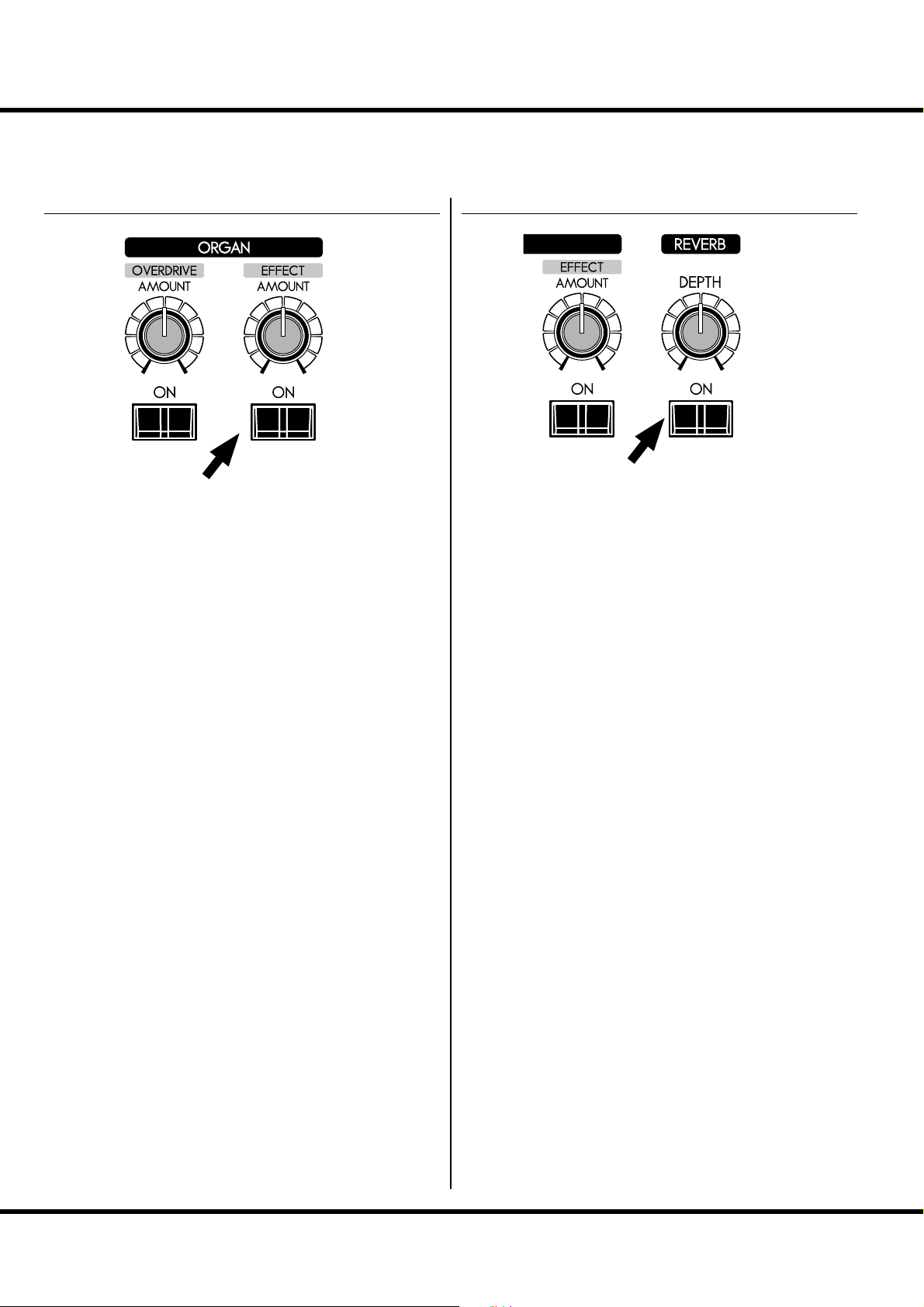
52
MULTI-EFFECTS, REVERB
e SKX has on-board Digital Multi-E ects and Reverb to enhance the Organ section.
MULTI-EFFECTS
[EFFECT ON] button
To engage the Muti-E ects. Press this button and the light will
go ON.
[EFFECT AMOUNT] knob
Adjusts the amount of the Multi-E ects.
NOTE: There are numerous parameters in the Multi-E ects. The de-
tailed settings of the parameters are adjusted on the control
panel. (P. 91)
REVERB
e Digital Reverb is common to both Organ and Extra Voice
sections.
[REVERB ON] button
To engage the Reverb, press this button and the light will go
ON.
[REVERB DEPTH] knob
Adjusts the depth of the Reverb.
NOTE: You can ne-tune the time etc. of the Reverb. (P.99)
Skx
Owner’s Manual
Page 53

PEDAL SUSTAIN, COUPLER
A popular option for playing the Pedals or Manual Bass is Pedal Sustain, which allows
the Pedal voice to smoothly decay upon release, much in the manner of a string bass.
Using the Lower keyboard, you can play the Pedal part together (Manual Bass).
e Pedal part can be played by Lower keyboard, or the Lower part can be played by
the extended Pedalboard (Lower To Pedal).
R
53
[PEDAL SUSTAIN] button
Touching this button will turn Pedal Sustain “ON” (LED lit) and “OFF” (LED not
lit).
After releasing your foot from the Pedalboard (or pressing and releasing a bass note
on the Lower keyboard when using Manual Bass, the sound will slowly fade, or decay.
NOTE: You can control the decay time of the Pedal Sustain (P. 73).
[MANUAL BASS] button
Touching this button will turn Manual Bass “ON” (LED lit) and “OFF” (LED not
lit).
If you played the Lower keyboard, the Pedal part will sounds together.
e default range of the Manual Bass is up to the middle “B”.
NOTE: You can change the upper note limit of the Manual Bass (P. 110 ).
NOTE: You can set the Manual Bass either to play the lowest note if multiple notes are
played or, if a chord is played on the Lower keyboard, to sound the root note of the
chord (P. 110).
[LOWER to PEDAL] button
is feature allows a connected MIDI Pedalboard to play the sounds registered for
the LOWER part in addition to whatever PEDAL registration may be selected.
Touching this button will turn Lower to Pedal “ON” (LED lit) and “OFF” (LED
not lit).
NOTE: You can change the upper limit playing range of Lower to Pedal (P. 110).
COUPLER
In the organ terminology, a “Coupler” is a device
which allows sounds from one part to be played on
another. Examples are Lower to Pedal and Manual
Bass.
Setting Up
Page 54
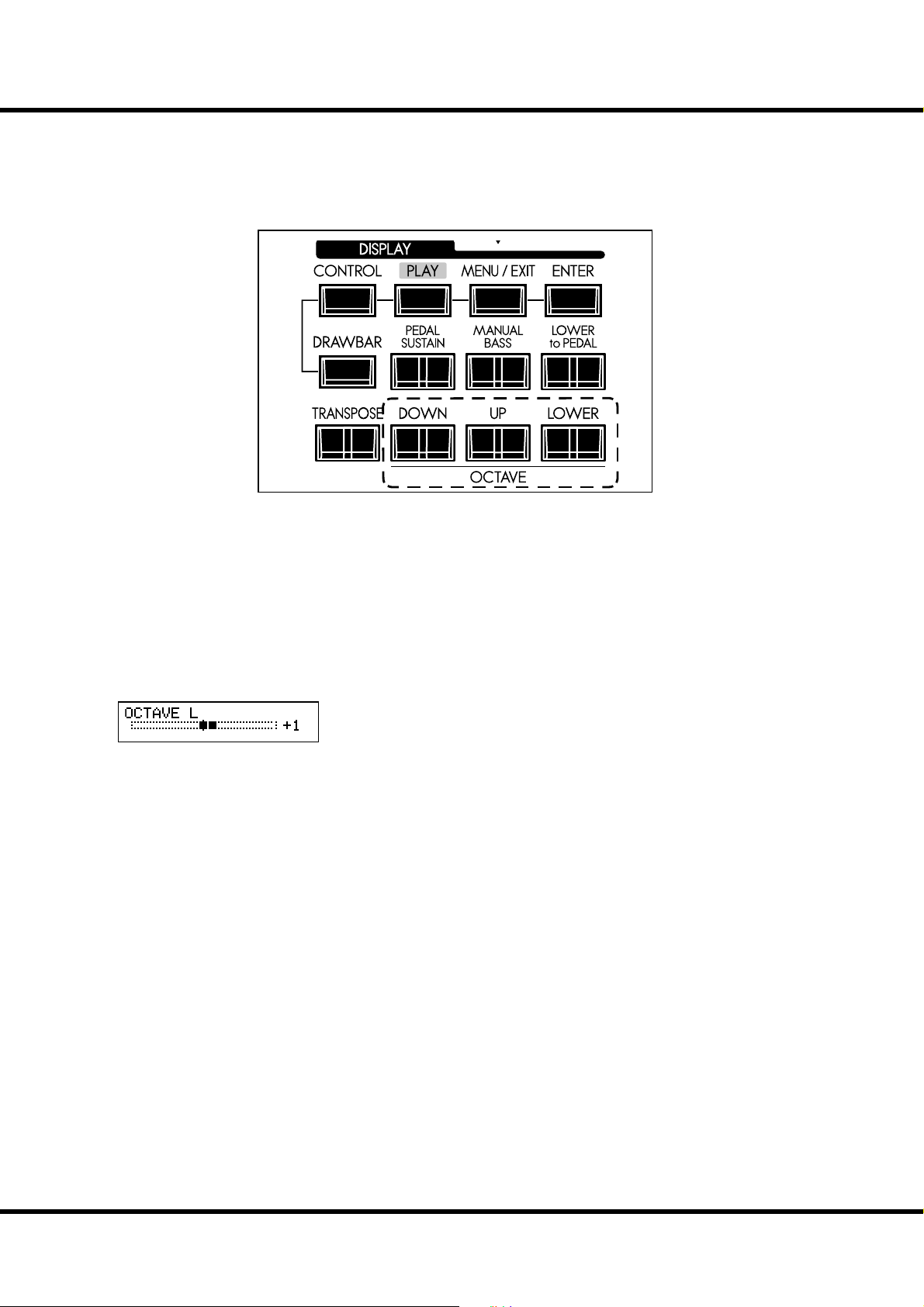
54
OCTAVE SHIFT
e keyboard can be shifted up or down in one-octave units to facilitate easier play.
R
[OCTAVE] buttons
Raises or Lowers each part by one-octave units within a range of ±2 octaves.
To raise the octave of the UPPER keyboard, press the [UP] button.
To lower the octave of the UPPER keyboard, press the [DOWN] button.
To raise the octave of the LOWER keyboard, press and hold the [LOWER] but-
ton and press the [UP] button.
To lower the octave of the LOWER keyboard, press and hold the [LOWER] but-
ton and press the [DOWN] button.
Octave of LOWER is at “+1”.
When changing octaves here, the status of the Octave is brie y shown on the display.
NOTE: OCTAVE buttons can be assigned various functions instead of the octave shift (P. 78).
NOTE: You can select whether the Octave setting changes while notes are being held or
when the next note is pressed after releasing the notes being held (P. 79).
Skx
Owner’s Manual
Page 55

TRANSPOSE
e Transpose function allows you to match the same key of other instruments or vocalists without changing the key that you are playing in.
For example, if you set Transpose at [+5], the note “F” sounds when you
play the “C” key. (By playing in the key of C the SKX sounds in the key
of F.)
R
55
[TRANSPOSE] button
To raise the pitch by semitone, press the [UP] button, while holding down the
[TRANSPOSE] button.
To lower the pitch by semitone, press the [DOWN] button, while holding down
the [TRANSPOSE] button.
You can set Transpose in the range from -6 to +6 semitone.
Transpose is at “+5”.
When performing this operation, the status of the transposition is shown in the
display.
Transpose is mapped to the following points:
i) Between the internal keyboards and the built-in sound engines.
ii) Between the MIDI IN and the built-in sound engines.
iii) To the External Zone.
iv) When the MIDI Pedalboard XPK-100 is connected, Transpose value will syn-
chronize with it.
NOTE: The Transpose is a temporary parameter, and is not recorded to any Patch. When the
power is switched OFF, it returns to 0.
NOTE: You can select whether Transpose changes while notes are being held or when the
next note is pressed after releasing the notes being held (P. 79).
Setting Up
Page 56
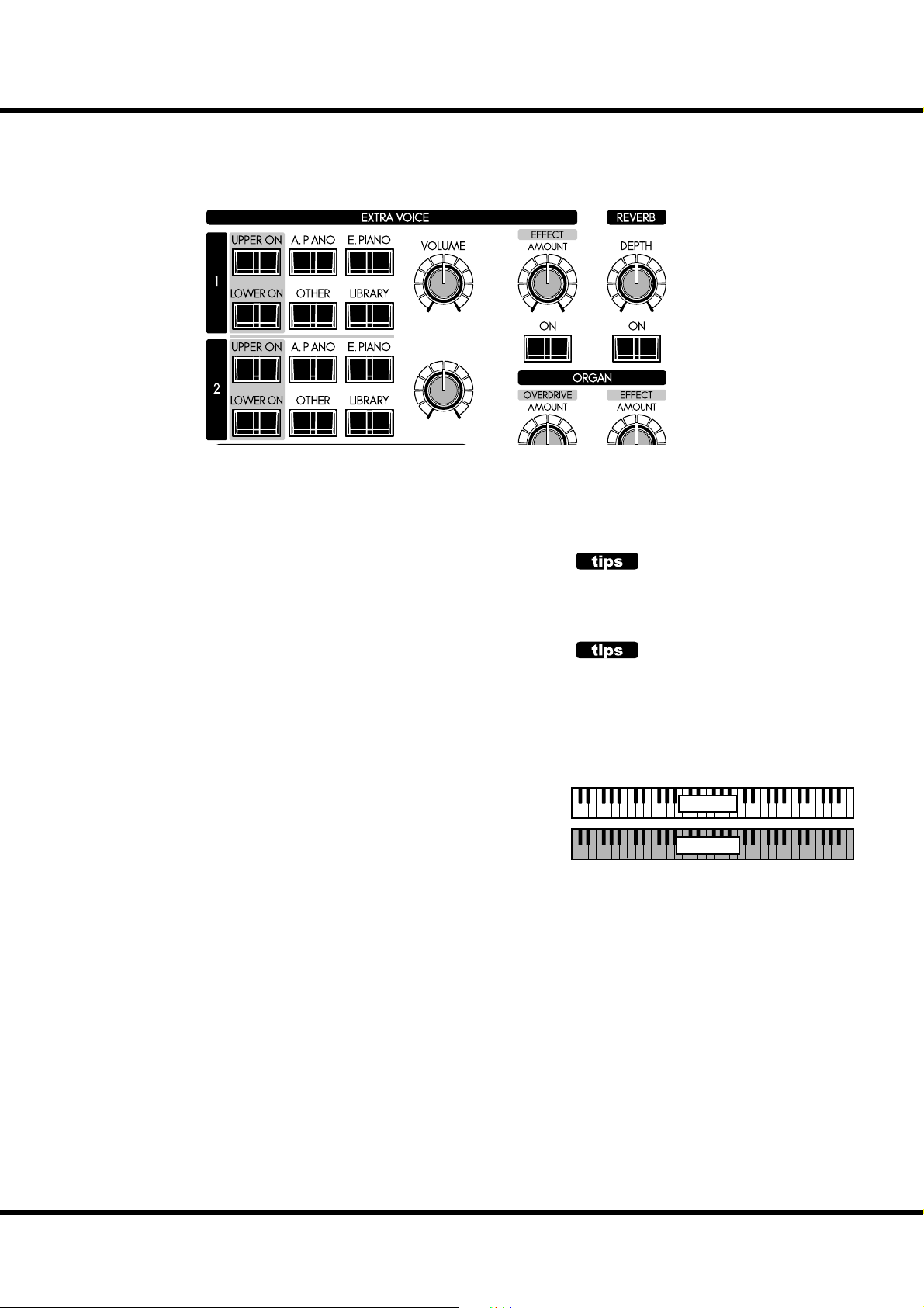
56
EXTRA VOICE SECTION
e EXTRA VOICE section contains the sounds other than Organ which comprise the SKX. As a system, you select which voice
ere are two sections of the Extra Voice on the SKX. e Organ
and Extra Voice sections can be played simultaneously.
to allocate to what part.
MIX
BALANCE
EXV1 EXV2
ALLOCATE
To play the Extra Voices, you must allocate them to either the UPPER or LOWER
parts. e Extra Voices can play alongside the Organ.
[UPPER ON], [LOWER ON] buttons
Selects either the UPPER/LOWER part to allocate Extra Voices. To play the Extra
Voices, press either button and (LED ON).
To CANCEL the Extra Voice allocation, press the desired button again (LED OFF).
NOTE: You can set that the Organ section turns “OFF” when an Extra Voice section is switched
“ON”. (P. 79)
BUILT IN SOUNDS AND LIBRARY
ere are 4 groups of resident sounds, corresponding to the Voice Groups. ese core
sounds may not be overwritten. You may expand this core with Voice Libraries which
can be download from the Hammond website.
To select instruments, see “SELECT INSTRUMENTS” on (P. 30), and the “INSTRUMENT LIST” (P. 136) for the built-in sounds.
EXTRA VOICE
The Extra Voice section on your SKX is not related
to, and does not replicate the sounds of F-100 “Extravoice” (1960’s).
PROCHORD™ FEATURE
Some of the Extra Voice instruments contain the
Prochord™ feature. These will have “Pcd” as a su x
added to their names.
If you allocate this instrument to the Upper part,
play a chord on the Lower keyboard and play a
single note on the Upper keyboard, you will hear
harmony added to the single-note melody.
MELODY
CHORD
Skx
Owner’s Manual
ProChord is a unique feature which allows you to
play professional right-hand harmony while playing a single-note melody. The harmonization applied to the melody is determined by the chord
played by the left hand.
When notes or chords are played on a Lower
keyboard and a note is played on an Upper keyboard, the note represented by the key played on
the Upper keyboard is heard along with a scored
harmony pattern which sounds according to the
Chord Root and Chord Type selected by the notes
played on the Lower keyboard. The Chord Root is
the letter name of the chord (F, A, B=, etc) while
the Chord Type is the denomination of the chord
(Major, Minor, etc.)
Page 57

MULTI-EFFECTS, REVERB
e SKX is equipped with Multi-E ects capable of adding various e ects to the Extra
Voices, and Reverb capable of adding the e ects of playing in a concert hall.
57
MULTI-EFFECTS
[EFFECT ON] button
To engage the Multi-E ects, press this button and the light
will go ON.
[EFFECT AMOUNT] knob
Adjusts the amount of the Multi-E ects.
NOTE: There are numerous parameters in the Multi-E ects. Detailed
settings are made with the parameters in the control panel.
(P. 97)
REVERB
TWO EXTRA VOICES AND MULTI-EFFECTS
Extra Voice
Extra Voice
Generator #2
Generator #1
llocate
oard
ussion
erdrive
EXV Balance
12
Overdrive
EXV Volume
Expression
Equalizer
There are two Extra Voice sections.
Each one can play a di erent instrument.
These e ects are set automatically
when the instrument is selected.
They are common to both Extra
Voice sections.
Reverb is common for both the Organ and the Extra Voice
sections.
[REVERB ON] button
To engage the Reverb, press this button and the light will go
ON.
[REVERB DEPTH] knob
Adjusts the depth of the Reverb.
NOTE: You can ne-tune the time etc. of the Reverb e ect. (P. 99)
Multi Effect
ere are two Extra Voice sections as shown as above, but the
e ects following are only one section such as Overdrive, Equalizer, and Multi-E ects.
e e ects are automatically set when the instrument on the
Extra Voice. If the Extra Voice 1 and 2 are used simultaneously,
the e ects are set by instrument which selected at last.
Setting Up
Page 58

58
e settings you have prepared can be recorded to User Patches.
“USER” AND “PRESET”
P A T C H
“FAVORITE”
buttons
1
23
MANUAL
exclusive
refer
refer
refer
Patches
First
U001
Second
U002
ird
U003
Fourth
U004
Fih
U005
November
U098
December
U099
“User” ends
U100
Preset begins
P001
Monday
P002
Tuesday
P003
Mezzo Forte
P098
Forte
P099
Fotissimo
P100
Manual
“VALUE”
knob
in PLAY mode
sequential
select
“P” are not rewritable
There are 100 USER and 100 PRESET
Patches as illustrated. e “User” Patch are
over-write capable. e “Preset” Patches are
not.
To call the Patch, select the Patch Number
with the [VALUE] knob in the Play mode
(P. 23).
To record the present setting to the Patch,
first give a name to it and designate the
Patch number before recording the Patch
(next page).
The [MANUAL] button on the left side
of the top panel shifts the focus to all the
current settings of the top panel, and the
current internal settings. It is used as a starting point for writing your own Patches, or
for the musician who prefers to register “by
hand” instead of using Patches.
P100
U003
U002
U001
Patch Name (ex: “First”)
F
Drawbars
Registraion
Percussion
Organ
Eects
and, Drawbar Parameters for Swell and Great
Extra Voice
Internal / External Zone
Extra
Voice
Eects
PATCH LOAD
Only the Drawbar registrations of each keyboard
were recorded to the preset of the B-3/C-3. But
many more parameters than the Drawbar registrations are recorded to the Patches on the SKX.
If you wish to keep the “traditional” style of registration (Drawbars only), Select the proper parameters in “Patch Load”. (P. 74)
Skx
Owner’s Manual
Page 59

NAME THE PATCH
59
① GO TO THE MENU MODE
Press the [MENU/EXIT] button.
Menu mode will be displayed.
② GO TO PAGE A
④ GO TO PATCH FUNCTION MODE
Press [ENTER] and go to PATCH Function mode.
⑤ INPUT NAME
If Page A is not displayed, go to Page A by pressing [] button.
③ SELECT THE “PATCH”
Press [] button twice and move the cursor to “PATCH”.
You can enter a name using up to 15 letters.
[],[] buttons: Moves the cursor.
[VALUE] knob: Selects letters.
e available characters include: Punctuation Marks (space - .
’ &), Numeric Characters (0 - 9), Upper-case Letters (“A - Z”),
and Lower-case Letters (“a - z”).
You must save the Patch in order for the Patch Name to be
remembered (as explained on the next page).
Setting Up
Page 60

PATCH - continued
60
RECORD TO THE PATCH
Example: RECORD TO “U032”
① ENTER THE NAME
② PRESS THE [RECORD] BUTTON
Enter the name of the Patch. (P. 59)
Press the [RECORD] button. A prompt will appear in the display allowing you to select the Patch you want to record.
③ SELECT THE PATCH NUMBER
④ PRESS [ENTER]
Select the Patch number you wish to record with the [VALUE]
knob ( is time select U032) or type the buttons such as [3]
[2].
Press the [ENTER] button. e Patch is con rmed and the
display will show the following for approximately ½ second:
Recording Patch...
When the recording is completed, the display returns to the
previous one.
NOTE: The recorded Patch data is retained if the power is switched
o or disconnected.
Skx
Owner’s Manual
Page 61

61
USING THE
CONTROL PANEL
Page 62

62
WHAT YOU CAN DO ON THE CONTROL PANEL
Your access to deep-editing the SKX. All of the parameters and all of the controls not covered
by the top panel knobs and switches are here.
e modes displayed are, basically “PLAY”, “MENU” and “FUNCTION”. See how to
read them and how to use the buttons on the next pages.
PLAY mode
MENU mode
FUNCTION mode
Skx
Owner’s Manual
Page 63

PLAY MODE
e Play mode is basic for all operations. All information necessary for ordinary performance
is displayed here.
To locate this mode
1. Play mode is normally displayed when the instrument is fi rst powered “ON.”
2. However, if you need to locate this mode from another display mode, touch the
[PLAY] button.
HOW TO READ THE DISPLAY
Drawbar Registration
UPPER / PEDAL / LOWER
Display of Registration
(Bars)
63
Display of Extra Voices
Display of Registration
(Digits)
OPERATION IN THIS MODE
There are three Play modes: 1. Graphic
Drawbar Display, 2. Numeric Drawbar
Display, and 3. Extra Voice Display. e
[PLAY] button allows you to are toggle
among these modes each time you touch it.
Patch
Select the Patch
Display the Menu mode.
Switch the three Play mode types.
Using the Control Panel
Page 64
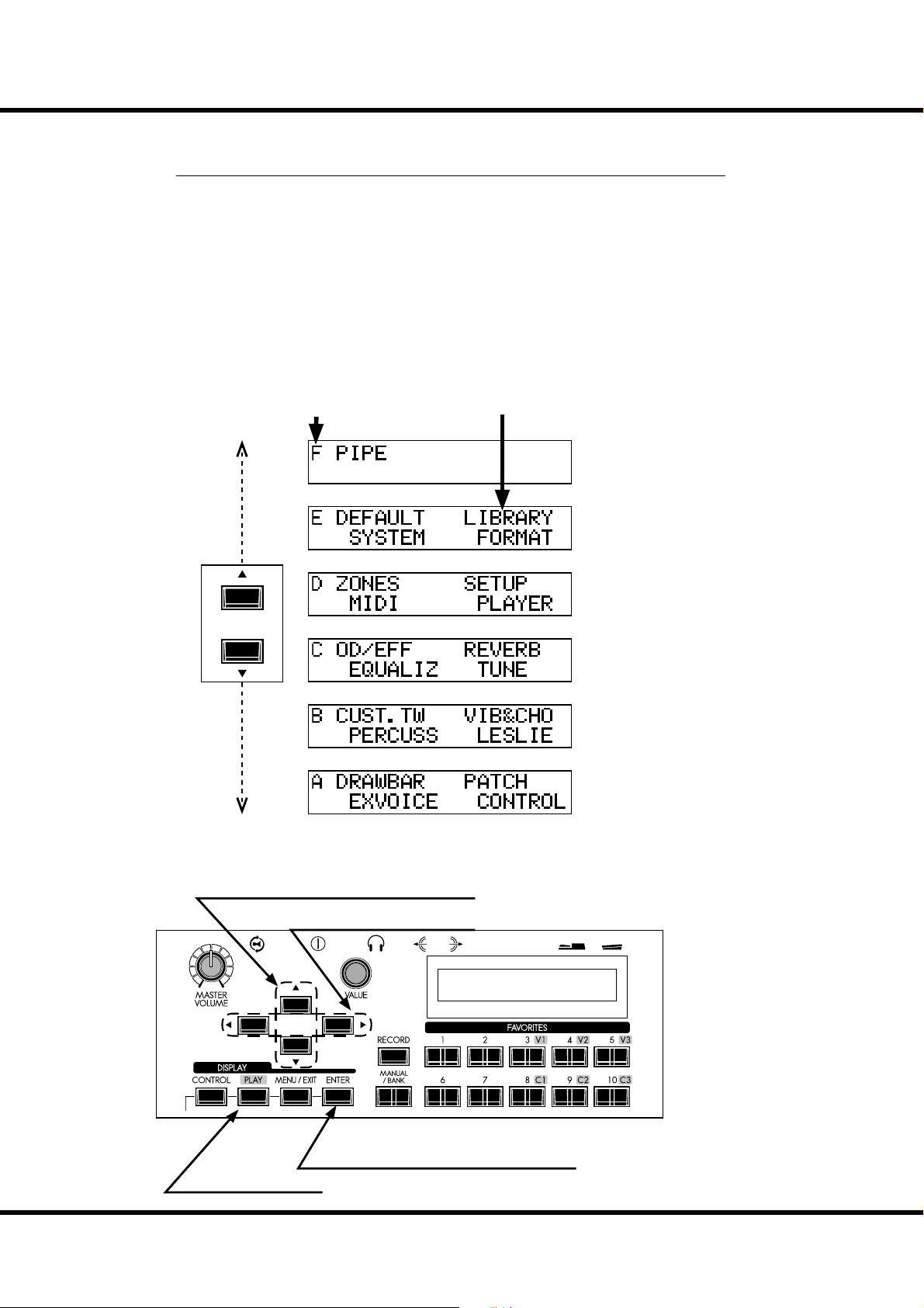
64
MENU MODE
e Menu mode provides a directory of all the various functions.
To locate this mode:
Press the [MENU/EXIT] button.
Use the [] and [] buttons to access the di erent Pages of the Menu mode.
ere are 6 pages in the Menu mode, labeled “A” through “F.” Each page has up to four
items.
Notice that one of the Menu items is ashing. Use the [] and [] buttons, or turn the
[VALUE] Rotary Knob to select the item you wish to edit.
When the item you want is ashing, touch the [ENTER] button. e Function mode
for the selected item will display.
HOW TO READ THE DISPLAY
Page Items
OPERATION IN THIS MODE
Move the page.
Select the item in the page.
Enter the selected Function mode.
Return to the Play mode.
Skx
Owner’s Manual
Page 65

65
MENU AND THE CONTENTS
PAGE A
1. DRAWBAR
Allows you to modify the characteristics of the Organ section
(sounds produced by the Drawbars.) (P. 72)
2. EXVOICE
Allows you to modify the characteristics (Volume, Note Range,
Velocity, etc.) of the Extra Voices. (P. 75)
3. PATCH
Allows you to name a Patch, select which parameters will load
and set assignment of Favorites. (P. 74)
4. CONTROL
Allows you to change how the various controls, such as Foot
Switch, Expression Pedal, etc., will function. (P. 76)
PAGE B
1. CUST. TW
Allows you to customize the Tone Wheel settings of the Lower
and Upper part for Organ section. (P. 85)
2. PERCUSS
Allows you to adjust the characteristics (Volume, Decay time,
Key Tracking, etc.) of the Percussion voices of the Organ section. (P. 80)
3. VIB & CHO
Allows you to adjust the characteristics of the Vibrato & Chorus. (P. 81)
4. LESLIE
Allows you to adjust the characteristics of the built-in Leslie effect and to adjust external Leslie speaker settings. (P. 82)
4. PLAYER
Allows you to utilize the Music Player to play audio les. (P. 127)
PAGE E
1. DEFAULT
Allows you to reset the SKX to various factory default settings.
(P. 101)
2. SYSTEM
Allows you to customize the System Parameter and display the
System information. (P. 102)
3. LIBRARY
Allows you to manage Voice Library of the Extra Voices. (P. 131)
4. FORMAT
Allows you to format a USB Flash Drive for use with the SKX.
(P. 117)
PAGE F
1. PIPE
Allows you to adjust the characteristics of the Pipe voices of the
Organ section. (P. 88)
PAGE C
1. O. D./EFF
Allows you to adjust the characteristics of the Overdrive and
Multi-E ects for both the Organ and Extra Voice sections. (P. 90)
2. EQUALIZ
Allows you to adjust the characteristics of Patch Equalizer and
Master Equalizer. (P. 98)
3. REVERB
Allows you to adjust the Reverb parameters. (P. 99)
4. TUNE
Allows you to set the tuning of the entire keyboard. (P. 100)
PAGE D
1. ZONE
Allows you to control the Internal and External Zones. (P. 110)
2. MIDI
Allows you to set the basic MIDI parameters for the instrument, and allows you to perform a MIDI Data Dump to a
MIDI data recorder or to another SKX. (P. 112)
3. SETUP
Allows you to Save or Load a Setup to or from a USB Flash
Drive. (P. 116)
Using the Control Panel
Page 66
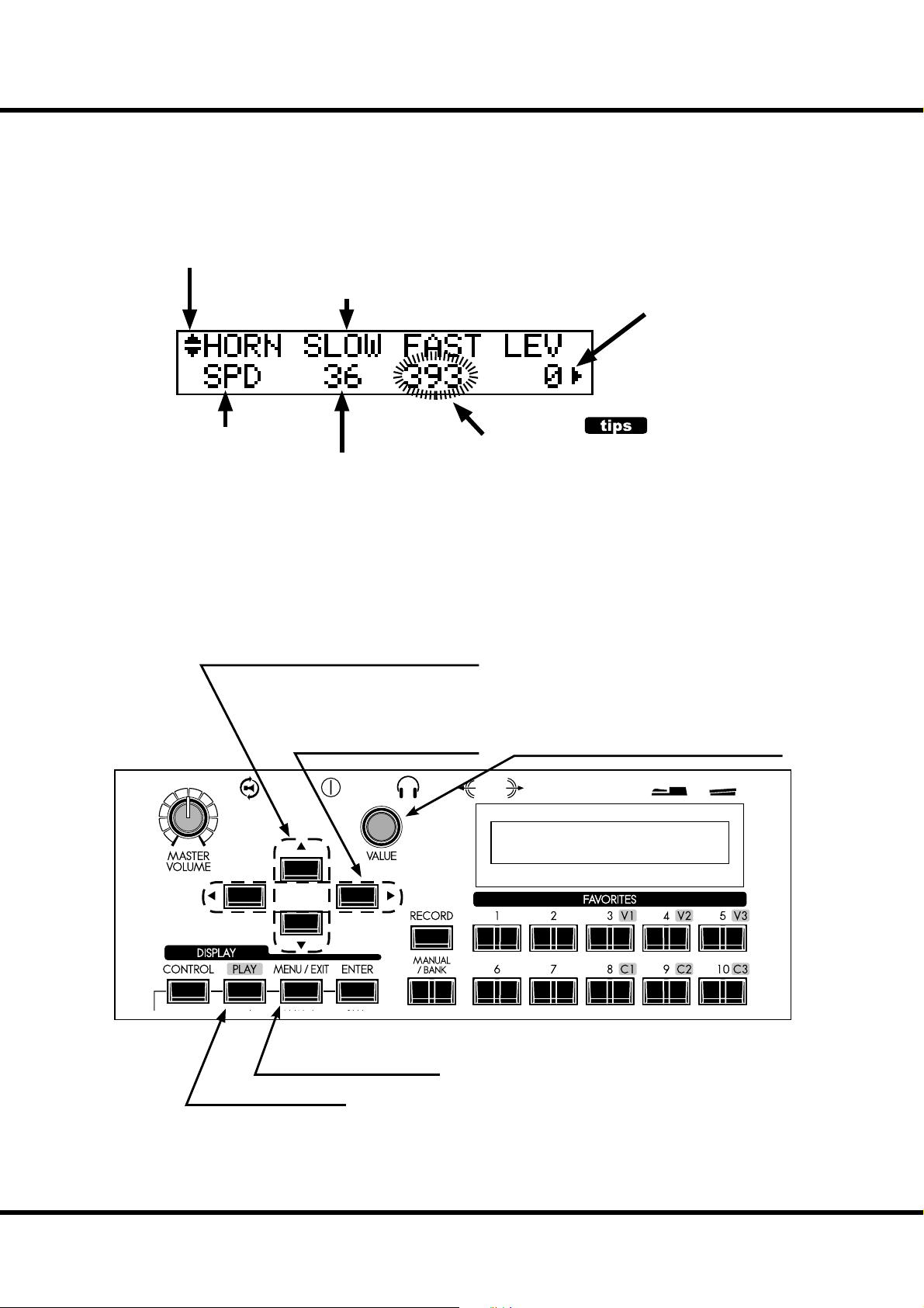
66
FUNCTION MODE
ese modes are for selecting and controlling the function.
All modes can be navigated the same way.
HOW TO READ THE DISPLAY
There is another page above (or below)
this page.
PARAMETER
(ITEM) name
Shows there is another page on the right (or the
left) of this page.
PAGE name
VALUE
OPERATION IN THIS MODE
Move the page up or down.
Moves the cursor left or right. The
cursor goes to the edge of the
screen, and, if there is another page
to the right or left, moves to that
page.
CURSOR
( ashing VALUE)
Adjust the value of the cursor location.
CURSOR
On the SKX, the cursor style is to Flash the entry.
Return to the Play mode.
Skx
Owner’s Manual
Jump to the Menu mode.
Page 67

PARAMETER OPERATION EXAMPLE:
ADJUST THE [FAST] PERCUSSION DECAY TIME “FASTER”
① LOCATE THE MENU MODE
ER
② SELECT THE MENU PAGE
67
Press the [MENU/EXIT] button.
e Menu mode is displayed.
ER
③ MOVE THE CURSOR TO THE FUNCTION MODE YOU WISH TO LOCATE
ER
③ PRESS [ENTER]
Find the “PERCUSS” using the [],[]
buttons.
“PERCUSS” is on Page B.
Move the cursor to “PERCUSS” using the
[],[] buttons.
Press the [ENTER] button. The display
shows the rst page of the Percussion Function mode.
ER
Using the Control Panel
Page 68
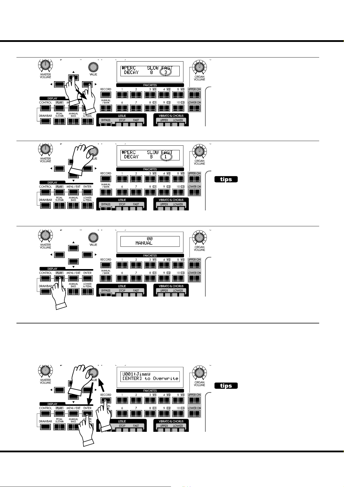
68
⑤ MOVE THE CURSOR TO THE PARAMETER YOU WANT TO CHANGE
ER
Decay time is on the “DECAY” page. Locate the “DECAY” page using the [][]
buttons.
“FAST” is on the right side of the page
move the cursor (blinking value) to the
right using the [][] buttons.
⑥ CHANGE THE VALUE
there must be
must be
ER
⑦ RETURN TO THE PLAY MODE
ER
Decrease the value using the [VALUE]
knob.
CONTINUE EDITING
If you want to change other items, repeat the process 1 to 6.
Press the [PLAY] button to return to the
Play mode.
⑧ RECORD TO THE PATCH IF NECESSARY
e parameter “DECAY FAST” is a Patch Parameter. If you select a di erent
Patch, the setting for the [DECAY FAST] button may change also.
However, you can make changes to any of the User Patches and record your
changes. Please see the PATCHES section of this Manual for more information about Patches.
ER
Skx
Owner’s Manual
PATCH PARAMETERS
A “Patch Parameter” is a parameter which is unique
to each Patch and can have a different value or
setting for each Patch. The settings of many of the
top panel controls such as Rotary Knobs, buttons,
etc. can be saved as Patch Parameters. A parameter
which is common to all Patches is called a Global
Parameter. For a complete listing of all Patch and
Global Parameters, please consult the APPENDIX
at the back of this manual.
Page 69
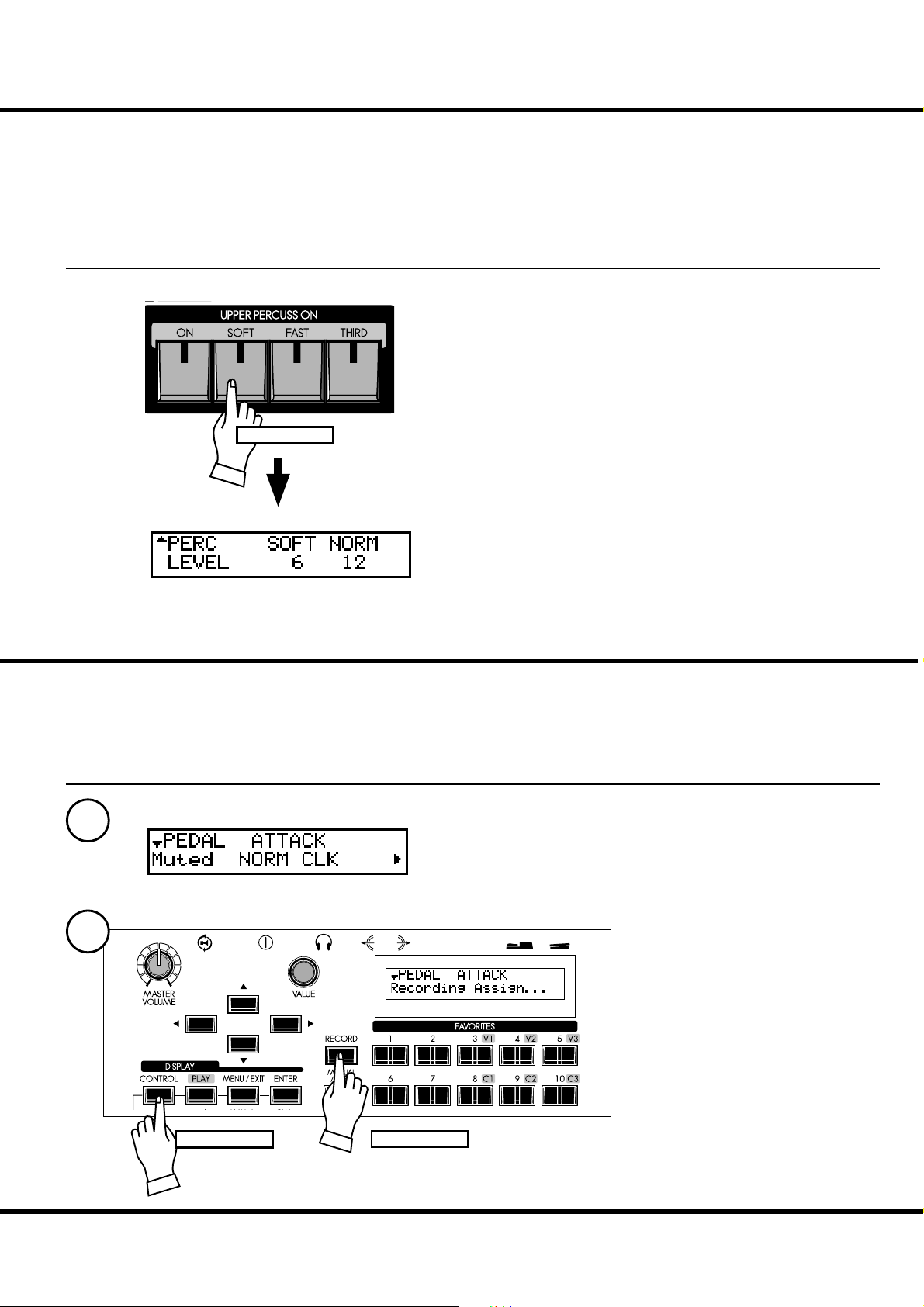
SHORT CUT TO FUNCTION MODE
To make programming quicker and easier, each button on the top panel can be used
to access the Function mode page associated with that button instantaneously.
Pressing and holding any of the buttons on the top panel automatically “shortcuts”
the display to the related Function mode item.
OPERATION EXAMPLE:
LOCATE THE PERCUSSION FUNCTION MODE
Press and hold
69
If you wish to edit the Percussion settings, Press and Hold any
of the four Percussion buttons ([ON], [SOFT], [FAST], or
[THIRD]) and the display will immediately show the Percussion Function Mode.
To see which buttons are associated with particular Shortcuts,
please consult the next chapter.
NOTE: You can change the Display Shortcut time. (P. 79)
REGISTER THE PAGES YOU FREQUENTLY USE
You can assign a frequently-used Function Mode page to the [CONTROL] button
for immediate access, even if that particular Function Mode is not normally accessible
via a Shortcut.
OPERATION EXAMPLE:
REGISTER THE “DRAWBAR - PEDAL” PAGE
1
2
Press with...
Press and hold
Display the page you want to register using the MENU etc.
Here, as an example, let’s display the “Drawbar - Pedal” page.
Press and Hold the red [RECORD]
button.
While holding the [RECORD] button,
press the [CONTROL] Touch Button.
e display will show, “Recording
Assign” for about 2 seconds.
You will be able to access the desired
page immediately by pressing the
[CONTROL] button.
Using the Control Panel
Page 70

70
DISPLAY LOCK MODE
You can lock the display to avoid accidentally changing something in the midst of playing. To do this, follow the instructions below.
To lock the display, turn the [POWER] to the instrument
“ON” with press and hold the [RECORD] and [MANUAL/
BANK] buttons until “Display LOCKED” is displayed.
To unlock this, repeat the operation above until “Display
UNLOCKED” is displayed.
is function works listed below;
[MENU/EXIT] button (P. 64) is disabled
[RECORD] button (P. 34) is disabled normally, but you can
record the Patch by using “LOCKED 1-10” (P. 70), or you
can associate the favorite buttons by using “ASSOCIATE”
(P. 74) before locking the display.
“Short-Cut” function (P. 69) is disabled
[UPPER / LOWER ON] buttons (P. 47) are still enabled.
[EXTRA VOICE] buttons (P. 30) are enabled, but the page
or cursor is locked on the instrument name.
NOTE: This feature will not released by Default-All or power on with
pressing [RECORD] button.
11 P I N
USING REGISTERED PAGE
You can still use the [CONTROL] button to access
a frequently-used Function mode page in Display
Lock mode.
However, you cannot move the cursor if the page
has two or more parameters.
Skx
Owner’s Manual
Page 71
71
SETTING THE
PARAMETERS
Page 72
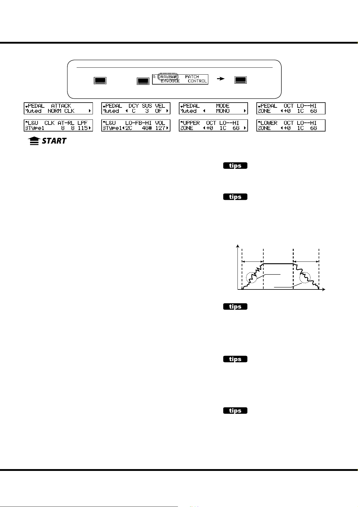
72
❶
❷❷❸❸❹
❺
❻❻❼
❽❽❾❾❿
⓫⓫⓬⓬⓭
⓮
⓯
⓰⓰⓱⓱⓲
⓳
⓴⓴
⓮
❶
Drawbar sound parameters for each keyboard are set in this mode.
To locate this mode:
⓯
❹
DRAWBAR
DRAWBAR
or,
See the “Function mode” (P. 66) for operational details.
MENU/
EXIT
❺
⓲
❼
⓳
❿
ENTER
⓭
SETTING FOR MANUAL (LOWER & UPPER) DRAWBARS
❶ ORGAN TYPE
Select the manual keyboard Organ Type.
BType1: Traditional B-3/C-3 Tone Wheel sound
BType2: Sound with more leakage noise and wow- utter
Mellow: With transparent sine waves
Vx: Transistor Organ, Vx type
Far t: Transistor Organ, Farf type
Pipe: Pipe Organ
When the Organ Type is set at Vx, Farf, or Pipe, the parameters (2) to (6) are unavailable.
❷ CLICK - ATTACK LEVEL
Sets the key-on click volume.
e higher the value, the louder the click gets. No key-click at 4. As the value goes
lower than 4, the attack rate becomes slower.
❸ CLICK - RELEASE LEVEL
Sets the key-o click volume.
e higher the value, the louder the click gets. No key-click at 4. As the value goes
lower than 4, the release rate becomes slower.
❹ CLICK - LOW PASS FILTER
Sets the key-click tone.
e setting range is 0 to 127. e higher the value, the brighter the sound.
❺ FOLDBACK - LOW
Sets the key-point from which the 16´ Drawbar folds back (= repeat the same octave
on the lower octaves of the keyboard).
e bottom key on the keyboard is displayed as “1C”. e setting range is 1C to 2C.
❻ FOLDBACK - HIGH
Sets the key from which the 1´ Drawbar folds back (= repeat the same octave on the
higher octaves).
e setting range is 4G to 5C.
NOTE: The Fold-back is possible not only with 1´ but also with 1⁄´, 1⁄´, 2´, 2⁄´ Drawbars.
❼ ORGAN VOLUME
Set the volume for the entire Organ section. It is related with [ORGAN VOLUME]
knob on the top panel. e setting range is 0 to 127.
❽ UPPER ZONE OCTAVE
Set the octave shift for the UPPER part. e setting range is -2 to +2.
❾❿ UPPER ZONE LOW / HIGH
Set the sounding range of the UPPER part with these two parameters.
TONE-WHEEL SET
There are variations available for each virtual
Tone Wheel set of BType1, BType2 and M ellow. (P. 85)
KEY CLICK
On the traditional models such as B-3/C-3, a noise
occurred when keys were pressed and released,
due to the mechanical keying system employed on
the classic organs. That characteristic is replicated
here.
Loudness
Attack
Rate
Attack
Click
Release
Click
Note On Note Off
Release
Rate
Time
EXAMPLES OF KEY-CLICK SET-
TINGS
Simulation of classic multi-contact keyboard
B-3/C-3: AT = 8, RL = 8
Simulation of a PCM synthesizer to produce the
key-click only at ‘attack’: AT = 8, RL = 4
Slow envelope like a pipe-organ: AT = 0, RL = 0
FOLD-BACK
As the number of the Tone Wheels was limited on
the B-3/C-3, the very highest and lowest pitches
“folded back” on the keyboards, sounding the
same octave twice in a row. This function reproduces this characteristic.
HOW DOES THE ORGAN VOLUME
WORK?
The organ volume adjusts just the volume after
multi-e ects unlike the Expression. It is useful for
set the volume of each Patch, or set the level balance between organ and extra voice section.
Skx
Owner’s Manual
Page 73

⓫ LOWER ZONE - OCTAVE
Set the octave shift for the LOWER part. e setting range is -2 to +2.
⓬⓭ LOWER ZONE - LOW / HIGH
Set the sounding range of the LOWER part with these two parameters.
SETTING THE PEDAL PART
⓮ ORGAN TYPE
Set the Organ Type for the Pedal part.
Normal: The traditional Tone Wheel sound of the B-3/C-3.
Muted: Analog oscillating sound as heard on the Classic X-5.
Synth1: Saw-tooth waveform with the lter-sweep.
Synth2: Dull square wave.
Finger: Electric bass, played by fore nger.
Pick: Electric bass, played by the pick with muted.
Slap: Electric bass, played with slap style.
When the “Pipe” Organ Type is selected by (1), only Pipe Organ pedal sounds are
heard, regardless of this parameter. Also, parameters (15) to (18) are unavailable.
⓯ ATTAC K
is allows you to set the Pedal Attack Rate and the Key-Click Volume at ‘attack’
and ‘release’.
MAX CLK: Immediate attack and the key-click is loud.
NORM CLK: Immediate attack and the key-click is normal.
SOFT CLK: Immediate attack and the key-click is soft.
NO CLK: A slightly slower attack without key-click.
SLOW: Slow attack without key-click.
⓰ DECAY RATE
is allows you to determine whether the Pedal voice remains at the same volume as
a note is held, or if the voice decays, as like a plucked string.
e setting range is 1(short) - 5(long) and C(continuous).
⓱ SUSTAIN LENGTH
is allows you to set the Release Rate (= the decay time after key release), when the
[PEDAL SUSTAIN] button is ON.
e setting range is 1(short) - 5(long).
NOTE: You can locate this page by holding down the [PEDAL SUSTAIN] button as well.
⓲ VELOCITY
is allows you to set the response to the Velocity. e setting range is OF and 1 -
4. At OF, the volume does not change however hard you play the key. As the value
increases from 1 - 4, the sounds gets louder even if the key is played softly.
⓳ KEY MODE
is allows you to set the Pedal polyphony.
MONO: If multiple notes are played, only the lowest note will sound.
POLY: Up to 8 notes will play simultaneously.
LAST: The last note you played will sound.
When using Manual Bass (P. 32), the PEDAL part sounds its own mode (P. 110 ) regardless of the setting of this parameter.
⓴ PEDAL ZONE - OCTAVE
Set the octave shift for the Pedal part. e setting range is -2 to +2.
PEDAL ZONE - LOW / HIGH
Set the sounding range for the PEDAL part with these two parameters.
73
Loudness
Note On Note Off
SUSTAIN
Unlike synthesizer nomenclature, on the SKX “Sustain” refers to note decay after note release. On a
synth envelope generator this setting would be
called “T4” or “Release”.
Played as
Attack
Decay = "C"
Decay =
"1" - "5"
Sustain =
"On"
It sounds
Time
"
2
1
3
Key Mode and sounding
ZONE
The “ZONE” in these pages sets sounding range
for each part of the Organ section which from -2C
to 8G. It comes from range of MIDI note numbers.
The internal sound engine of the SKX receives all
the MIDI note number against internal keyboards
which has 5 octave, 1C to 6C.
There are more “ZONE”, Internal Zones and External
Zones. See page 106 for details.
J
MONO LAST
(Lowest)
NOTE: All the parameters in these pages are
Patch Parameters. They are recorded
into the Patch.
Setting the Parameters
Page 74

74
❶
❷❷❸
❺
❻
❼
❽
❾❾❿❿⓫
⓬
⓭
⓮
⓯
❹
In this mode you a name your Patch, set which parameters load, and how to link to
the Favorite buttons.
To locate this mode:
MENU/
EXIT
See the “Function mode” (P. 66) for operational details.
⓮
⓯
⓭
❶
❸
❹
❺
PATCH NAME
❶ Patch Name (P)
Name the present Patch using up to 15 letters.
Move the cursor by the [][] buttons. en select letters
with the [VALUE] knob.
e Patch name is lost, unless you save the Patch.
NOTE: This parameter (P) is a Patch parameter. It is recorded in each
Patch.
PATCH LOAD
ese are for setting which parameters are loaded when a Patch
is called. Sets whether or not to load:
❷❸❹ PATCH LOAD - DRAWBAR REGISTRATION (G)
Drawbar registration of the UPPER, LOWER and PEDAL
part.
❺ PATCH LOAD - DRAWBAR (G)
e parameters speci c to the Organ Section such as Organ
Type or Percussion.
❻ PATCH LOAD - EXTRA VOICES (G)
Extra Voice parameters.
❼ PATCH LOAD - INTERNAL ZONE (G)
e parameters relating with Internal Zone or Coupler (Pedal
to Lower and Manual Bass).
❽ PATCH LOAD - EXTERNAL ZONE (G)
e parameters speci c to the External Zone to control external MIDI equipment.
❾ PATCH LOAD - DRAWBAR EFFECT (G)
e parameters speci c to the Organ Section E ects (Overdrive, Multi-E ects, Equalizer).
❿ PATCH LOAD - ANIMATION (G)
e parameters speci c to the Leslie, Vibrato & Chorus e ects.
⓫ PATCH LOAD - EXTRA VOICE EFFECTS (G)
The parameters specific to the Extra Voice Section Effects
(Overdrive, Multi-E ects and Equalizer).
P A T C H
❻
⓬ PATCH LOAD - REVERB (G)
FAVORITES
⓭ FAVORITE ACCESS (G)
⓮ FAVORITE - BANK / NUMBER (G)
⓯ FAVORITE - PATCH (G)
ENTER
⓬
❼
❽
⓫
e Reverb parameters.
NOTE: Each Patch Load parameter is a Grobal parameter. It is re-
corded when the value is set. Common for each Patch.
Allows you to select how the Favorite buttons function.
ASSOCIATE:
Each number button usually calls the related Patch.
If you touch each number button holding down the [RECORD]
button, it relates the number button to the currently selected
Patch.
OVERWRITE:
In addition to above, if you touch each number button holding
down the [RECORD] button, it records the current setting to the
selected Patch.
LOCKED 1-10:
The Favorites and Patches made xed linkage. Each number but-
ton usually calls the corresponding Patch, U001 ... U100 by with
using [ BANK] button together.
If you touch each number button holding down the [RECORD]
button, it records the current setting to the corresponding Patch,
U001 ... U100.
DIRECT:
This is for directly calling the Patch, using each number button.
To call the Patch, rst put in the 3 digit Patch number and then
touch the [ENTER] button.
U001 ... [1], [ENTER]
U010 ... [1], [10], [ENTER]
U100 ... [1], [10], [10], [ENTER]
P001 ... [1], [10], [1], [ENTER]
P010 ... [1], [1], [10], [ENTER]
P100 ... [2], [10], [10], [ENTER]
You can not relate the Patch to each number button.
Displays and changing the Patches related with each Number
button [1] - [10].
You can enter the these page by pressing and hold the Number
button [1] - [10] also.
NOTE: “G” means “Global”. These parameters will be recorded when
set, and are common in each Patch.
Skx
Owner’s Manual
Page 75

MENU/
❶❶❷❷❸
❼
❽
❾
❹❹❺❺❻
EXIT
❻
EXVOICE ( Extra Voices)
In this mode the basic Extra Voice settings are made such as the Extra Voice
instrument and volume.
To locate this mode:
or, touch either button in the voice group.
See “Function mode” (P. 66) for operation details.
❼
❽
❾
75
ENTER
❶ VOLUME
❸
Adjust the volume of the entire Extra Voice sections here. It is
linked with the [VOLUME] knob on the top panel.
e setting range is 0 to 127.
❷ BALANCE
Adjust the volume balance between Extra Voice section 1 and
2. It is linked with the [BALANCE] knob on the top panel.
e setting range is 64:0 - EVEN - 0:63. It makes same volume
balance at EVEN.
❸ EXPRESSION
Sets the ON (enable) or OFF (disable) the Expression control
of the entire Extra Voice sections.
NOTE: This parameter cannot set for each Extra Voice section.
❹ ZONE - OCTAVE
Sets the playing octave for the Extra Voice section.
e setting range is -2 to +2.
❺ ZONE - LOW
❻ ZONE - HIGH
Sets the sounding range in the Extra Voice section with these
two parameters.
❼ VOICE GROUP
Sets the Voice Group. Choices are in the range of “A. Piano”
to “Library”, same as the [VOICE GROUP] buttons on the
top panel.
e operation of this parameter is di erent with which [VOICE
GROUP] button is selected.
A. PIANO, E. PIANO:
According with each [VOICE GROUP] button, not selectable.
OTHER:
Selects “Keyboard”, “Wind” or “Others”.
LIBRARY:
Selects the loaded Voice Libraries. “Tr. Organ VxJ” is pre-loaded.
❽ INSTRUMENT
Selects the instrument in the Voice Group.
Consult the instrument list at the back of this manual (P. 136) for
details.
❾ VELOCITY
Sets the response to the velocity (strength of the key touch) of
the Extra Voice section.
e setting range is OF, 1 to 4. At OF keys sound at a certain
volume, regardless of the key touch strength (like an organ’s
touch). “1” is the most exaggerated velocity curve while “4” is a
gentler curve. “2” and “3” are curves in between.
NOTE: All the parameters in this mode are Patch parameters, and are
recorded to each Patch.
OPERATING THE OTHER AND LI-
BRARY
The [OTHER] and [LIBRARY] button contains the 2
or more Voice groups. You can select this by pressing the each [OTHER] or [LIBRARY] button again instead of the turning the [VALUE] knob at the VOICE
GROUP parameter.
LINK BETWEEN INSTRUMENTS
AND OTHER PARAMETERS
When an instrument is selected, each parameter of
the Octave, the Multi-E ects, the Equalizer, Expression and the ProChord (although not displayed), is
automatically set at the recommended value.
Setting the Parameters
Page 76
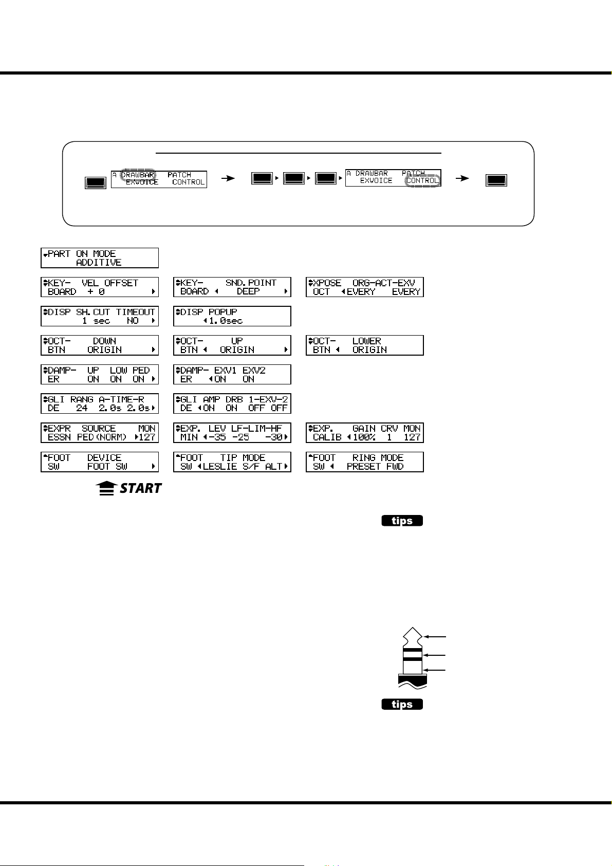
76
❶
❷
❸
❹
❺
❻❻❼
❽
❾❾❿
⓬⓬⓭
⓲⓲⓳⓳⓴
⓫
⓮⓮⓯⓯⓰⓰⓱
❺
CONTROL
is mode is for setting the various controls.
e Foot Switch and Expression Pedal requires setting before using if
connected. It is possible to assign the [OCTAVE] buttons to other functions.
To locate this mode:
MENU/
EXIT
⓫
❹
⓭
or, touch the [CONTROL] button.
See “Function mode” (P. 66) for operation details.
⓴
❺
❼
❽
⓱
❿
❺
ENTER
❶
❷
FOOT SWITCH
❶ FOOT SWITCH - DEVICE (G)
is is for selecting the equipment connected to the FOOT SWITCH jack.
FOOT SW: Foot Switch connected.
CU-1: Optional Leslie Mode Switch (CU-1) connected.
❷ FOOT SWITCH - TIP MODE (G)
is sets the Foot Switch function.
OFF: ...................................... Does not function.
LESLIE S/F ALT, MOM, TRI:
Switches the Leslie E ect Slow/Fast/Stop.
At ALT, Fast / Slow or Stop (as set by the [STOP] button) is toggled every time the foot
switch is pressed. At TRI, it is switched to Stop when the foot switch is further held down
for longer than a second.
At MOM, it is switched to Fast only while the foot switch is held down. When released it
switches to Slow or Stop (as set by the [STOP] button).
GLIDE: ................................. The pitch bends while the foot switch is pressed. The glide interval and
PATCH FWD, REV: ........... Switches the Patch Forward or Reverse.
FAVORITE FWD, REV: ... Switches the Favorite Forward or Reverse.
SPRING: .............................. This generates the sound of the spring reverb being shaken.
DELAY TIME: ..................... This is for setting the delay time (P. 99) of the Reverb, at the interval of tap-
MUSIC START: .................. Controls the Start/Stop of the Music Player.
MANUAL BASS: ............... Triggers the Manual Bass (P. 32) note of Pedal part.
glide speed is determined by the GLIDE - RANGE and GLIDE - TIME settings.
ping the foot switch. The delay sound goes out, while the foot switch is
held down.
❸
TIP AND RING
The typical stereo plug, there are 3 metal parts.
The end is called the “Tip”, the middle portion is
the “Ring”. The part on the cord side is called the
“Sleeve”.
The SKX requires a foot switch that uses a Stereo
Jack. Two Mono-Jack foot switches may be used,
and can have discrete functions, if a Left/Right
stereo splitter is used.
Tip
Ring
Sleeve
SPRING REVERB
The Hammond Organ company actually invented
the spring reverb for its organs in the 1940’s. The
e ect was obtained with a length of spring and a
few pickups. If the spring was disturbed, it would
make a large crashing noise that was usually considered a nuisance, but sometimes was used as a
program sound e ect. The Reverb here is digital,
but the “crash” e ect is re-created here.
Skx
Owner’s Manual
Page 77

77
BASS 1C - BASS 3C: ....... Triggers the speci c Pedal part note.
PROCHORD CLOSE, OPEN:
Triggers the ProChord note for the Organ section with speci ed voicing (close or open).
❸ FOOT SWITCH - RING MODE (G)
is sets the Ring side function, when the foot switch connected to the foot switch
jack is of the TRS speci cations.
NOTE: The “ProChord” function cannot be chosen via the “ring”.
EXPRESSION
❹ EXPRESSION - SOURCE (G)
Sets the source of Expression control.
PED (NORM):
For the (Optional) Hammond-Suzuki EXP-50J pedal etc.
PED (REV):
For using a Korg XVP-20 type of Expression Pedal etc.
MIDI: For using Expression information received at the UPPER Keyboard channel.
BOTH (NORM), BOTH (REV):
Expression value will controlled by both pedal and MIDI in.
❺ EXPRESSION - MONITOR
Displays the current value of Expression. In case of no sound or no change when
the Expression pedal is pressed, this monitor shows whether the Expression value
changes or not, so you may discover the cause of trouble (if any). is can also be an
indicator when playing from low volume to fade in.
❻ EXPRESSION - MINIMUM LEVEL (G)
Sets the volume at minimum Expression.
e setting range is OFF, -40dB to 0dB. At OFF the keyboard is silent when Pedal is
at Minimum (all the way back). e other value points represent the lowest volume
that will be present at the Pedal’s minimum position.
❼ EXPRESSION - LIMIT LOW FREQUENCY (G)
❽ EXPRESSION - LIMIT HIGH FREQUENCY (G)
Sets the amount of Low or High Frequency to remain, when the Expression is set at
minimum.
e setting range is OFF, -40dB to 0dB. At OFF the sound totally disappears, but
at other value points the set volume is kept, even if the Expression is at minimum.
❾ EXPRESSION - GAIN (S)
Sets the gain (range) of the connected Expression pedal.
e setting range is 70 to 130%.
Depending on the type of the connected Expression pedals, the Expression value
may not change enough. In such case, adjust this parameter to obtain the desired
response.
❿ EXPRESSION - CURVE (S)
Adjusts change of Expression value corresponding to the angle of the depressed Expression pedal.
e setting range is 1 to 3. Refer each curve to the bottom right illustration or try
playing live to discern which curve is correct for you.
NOTE: The parameters indicated by (S) are system parameters. They are recorded when set,
and are common in each Patch.
PROCHORD
“ProChord” function which adds complex harmonic voicing to single notes played on the UPPER
manual based on chord structures played on the
LOWER manual.
The ProChord by the foot switch a ects only for
the Organ section.
Played as
LOWER UPPER
It sounds
CLOSE OPEN
EXPRESSION LIMIT
One of the human ear’s characteristics is that when
the volume falls, the sound of the high or low frequencies becomes di cult to hear. Using Expression limit, you can hear the revised frequency response.
Vintage B-3/C-3 preamps age in di erent ways-one
symptom is the organ’s timbre may change with
Expression pedal travel. This is a desirable characteristic for some.
Loudness
Expression = Maximum
LF
Limit
120Hz 4kHz
Loudness
Expression = Minimum
LF
Limit
120Hz 4kHz
Value
127
0
Output
Min. Level
Output
Min. Level
HF
Limit
Frequency
HF
Limit
Frequency
3
2
1
Degree
NOTE: The parameter with (P) indicated is
a Patch parameter, and is recorded to
each Patch. (G) indicates “Grobal parameter”, which is recorded upon being set,
and is common with each Patch.
Setting the Parameters
Page 78

CONTROL - continued
❶
❷
❸
❹
❺
❻❻❼
❽
❾❾❿
⓬⓬⓭
⓲⓲⓳⓳⓴
⓫
⓮⓮⓯⓯⓰⓰⓱
❺
78
⓫
❹
❶
⓭
⓴
❺
❼
❷
❽
⓱
GLIDE
⓫ GLIDE - RANGE (P)
Sets the pitch-bend range by semitone. Setting range is -24 to +12.
⓬ GLIDE - ATTACK TIME (P)
Sets the amount of time for the Glide e ect to reach the pitch set at (11). e setting
range is 0.1 to 5.0 seconds.
⓭ GLIDE - RELEASE TIME (P)
Sets the amount of time to return to normal pitch when the Glide is released.
⓮ GLIDE - AMP (P)
Engages a “fade” along with the Glide, where the volume drops in tandem with the
pitch to total silence.
⓯ GLIDE - DRAWBARS (P)
⓰ GLIDE - EXTRA VOICE 1 (P)
⓱ GLIDE - EXTRA VOICE 2 (P)
Assigns the Glide to the various sections of SKX. (15) is for Organ section, and (16)
and (17) are for the Extra Voice section.
❿
❸
❺
GLIDE
Since there is no pitch-bend function on the
B-3/C-3, some musicians would get a pitch-bend
e ect by quickly turning the power to the organ
“OFF” then “ON”.
If the RUN switch on a B-3/C-3 is turned o , the
Tone Wheel motor gradually slows down and
stops, and the ampli er turns o as well. You can
replicate this e ect using this function.
The SKX has added some parameters for Extra
Voice section to use as a simple pitch bend.
When Glide range is set at “-1”.
DAMPER
⓲ DAMPER - UPPER (G)
⓳ DAMPER - LOWER (G)
⓴ DAMPER - PEDAL (G)
DAMPER - EXTRA VOICE 1 (G)
DAMPER - EXTRA VOICE 2 (G)
Assigns the Damper function to the various divisions of the SKX.
(18), (19) and (20) are for setting each part of the Organ section, and (21) and (22)
are for the Extra Voice section.
ASSIGN
OCTAVE BUTTON - DOWN (G)
OCTAVE BUTTON - UP (G)
OCTAVE BUTTON - LOWER (G)
Used to assign extra functions other than the original ones to the [OCTAVE] but-
Skx
Owner’s Manual
DAMPER
Or “Sustain” pedal-analogous to the RIGHT pedal
on a piano. Sounds are held when this pedal is
depressed. Called “Damper” due to the fact that
when the pedal was depressed on a piano, the
mechanism that muted or “damped” the strings
was raised, allowing the piano strings to ring free.
Page 79

79
tons.
ORIGIN:............................... Works according to the buttons’ original function.
LES STOP, LES FAST:......Similar to the [LESLIE STOP], [LESLIE FAST] buttons.
VIB UPPER, VIB LOWER:
............................................... Similar to the [VIBRATO UPPER], [VIBRATO LOWER] buttons.
GLIDE: ................................. This is for activating the Glide function.
SPRING: .............................. This is for producing the shock noise of the Spring Reverb.
DELAY TIME: ..................... Sets the Delay Time (P. 99) by tapping the button at the interval you wish
the delay to be set. If you keep pressing the button, the Delay sound
disappears.
PRIO UPPER, PRIO LOWER:
Priority on Drawbars - Temporarily substitutes the Upper registration with Upper or
Lower Drawbar settings instead of the Patch content.
DISPLAY
DISPLAY - SHORTCUT (G)
Sets the shortcut waiting time.
e setting range is 0 to 2 seconds. At NO the shortcut feature is disabled.
DISPLAY - TIME OUT (G)
Sets the time for returning to the previous mode from the mode displayed by the
shortcut operation.
e setting range is 4 to 16 seconds. At NO the screen will not return to the previous mode.
DISPLAY - POP UP (G)
Sets the interval at which the Pop Up is displayed when you move the [OVERDRIVE] or [EFFECT AMOUNT] knob.
e setting range is 0.5 to 2 seconds. At NO no Pop Up is displayed.
KEYBOARD
VELOCITY OFFSET (S)
Fine-adjusts the keyboard velocity to personal taste. e setting range is -32 to +32.
If your touch is heavy, set this parameter to a negative value, if your touch is light, set
the parameter to a positive value.
SOUNDING POINT (S)
Set the sounding point if the internal keyboard is played.
DEEP: All the section sounds on the deep point in the stroke.
AUTO: The Organ section sounds on the shallow point if the [UPPER ON] / [LOWER ON] of the
Extra Voice section are “OFF”.
NOTE: The External Zone sends notes on at shallow point, and the velocity value is xed at
100 when the Sounding Point is set at AUTO, and the [UPPER ON] [LOWER ON] of the
Extra Voices are “OFF”.
TRANSPOSE/OCTAVE ACT - ORGAN (S)
TRANSPOSE/OCTAVE ACT - EXTRA VOICE (S)
Set the whether Transpose instantly or not by pressing the [TRANSPOSE] and
[OCTAVE] buttons.
EVERY: The transposed notes sounds at every pressed the buttons.
NEXT: The transposed notes sounds at next note on.
PART
PART ON - MODE (G)
Sets how performs [ON] buttons of the Organ Section and Extra Voice Section.
ADDITIVE: Each [ON] button turns its respective section “ON” and “OFF” independently.
ALTERNATE: Each [ON] button cancels the other on the same part. For example, the Organ [UP-
PER ON] button, when switched “ON”, will turn the Extra Voice [UPPER ON] button
“OFF”. To turn both sections “ON”, press the two buttons simultaneously.
DRAWBAR PRIORITY
PRIO UPPER and PRIO LOWER allows to make playing style which using Adjust Preset keys [A] or [B]
of the B-3/C-3 (below gure).
Patch’s Registration
UPPER Drawbars
with Percussion
PRIO. UPPER
LOWER Drawbars
as [B]
Preset key
PRIO. LOWER
as [A]
normal
UPPER Registration
For example, during the button for PRIO LOWER
(right side in the gure) is “ON”, the UPPER registration can be controlled only via LOWER Drawbars.
UPPER Drawbars (center in the figure) does not
a ect any parts.
By using this manners, you can preparing the
“next” registration on the UPPER Drawbars during
playing, and switch on the button for PRIO UPPER
to use the registration on the UPPER Drawbars immediately.
NOTE: The Percussion does not sound during
the PRIO LOWER is ON.
Preset key
AUTO DEEP
EXV Allocate is OFF.
EXV Allocate is ON.
EXV Allocate is OFF.
EXV Allocate is ON.
Sounding Point and keystroke.
NOTE: The parameter with (P) indicated is
a Patch parameter, and is recorded to
each Patch. (G) indicates “Grobal parameter”, (S) indicates “system parameter”,
which is recorded upon being set, and is
common with each Patch.
Setting the Parameters
Page 80

80
❶❶❷
❸❸❹
❺❺❻❻❼
❽
❾
MENU/
EXIT
PERCUSS ( Percussion)
is mode is for setting the parameters of the Percussion sounds.
To locate this mode:
or, keep pressing either of the [ON], [SOFT], [FAST], [THIRD] buttons for a
moment.
See “Function mode” (P. 66) for operation details.
❽
❾
ENTER
❶ LEVEL SOFT
❷ LEVEL - NORMAL
Controls the Percussion volume levels. e Normal level is
set by the NORM setting, and SOFT is the level when the
[SOFT] button is ON.
❸ DECAY - SLOW
❹ DECAY - FAST
Controls the Percussion decay time. e Slow rate is set by
SLOW setting, and Fast is the time when the [FAST] button
is ON.
e setting range is 1 to 9 and C. As the value is raised, the
decay time grows longer. At C (continuous) there is no decay,
and the Percussion sound is sustained while keys are pressed.
❺ KEYBOARD - TOUCH
Sets the touch response of the Percussion.
ON: Legato playing will result in the First note hit engaging the Per-
cussion, and none after.
OFF: The envelopes reset with each key hit and Percussion sounds on
every note.
❻ KEYBOARD - VELOCITY
Links the Percussion volume to velocity.
ON: A harder strike produces a louder Percussion sound.
OFF: Regardless how hard you play, the volume remains the same.
❼ KEYBOARD - KEY TRACK
Attenuates the Percussion volume by position of the key.
ON: The higher the note is, the lesser the volume.
OFF: no change in volume.
❼
❹
❷
❽ DRAWBAR - 1´ CANCEL
Mutes the UPPER 1´ Drawbar while using the Percussion.
ON: Mute active
OFF: No mute.
❾ DRAWBAR - LEVEL
Reduces the UPPER Drawbar volume while using the Percussion (except [SOFT] button is ON).
-5dB: Reduces the volume in similar response to the classic B-3/C-3.
-3dB: Slight reduction in volume.
0dB: Does not reduce the volume.
NOTE: All the parameters of these modes are Patch parameters, and
are recorded to the respective Patches.
TOUCH-RESPONSE
The Percussion generator on the vintage B-3/C-3
had a single envelope, which would not recycle
until all keys were raised. Originally thought to be
a defect, the resulting response became a desired
trait.
1´ CANCEL
The B-3/C-3 had no exclusive key contact for the
Percussion, but, used the 1´ contact. This is simulated on the SKX.
DRAWBAR LEVEL
When the Percussion was activated on the B-3/C-3,
the volume of the Drawbars became slightly softer
in volume. This is simulated on the SKX.
Skx
Owner’s Manual
Page 81
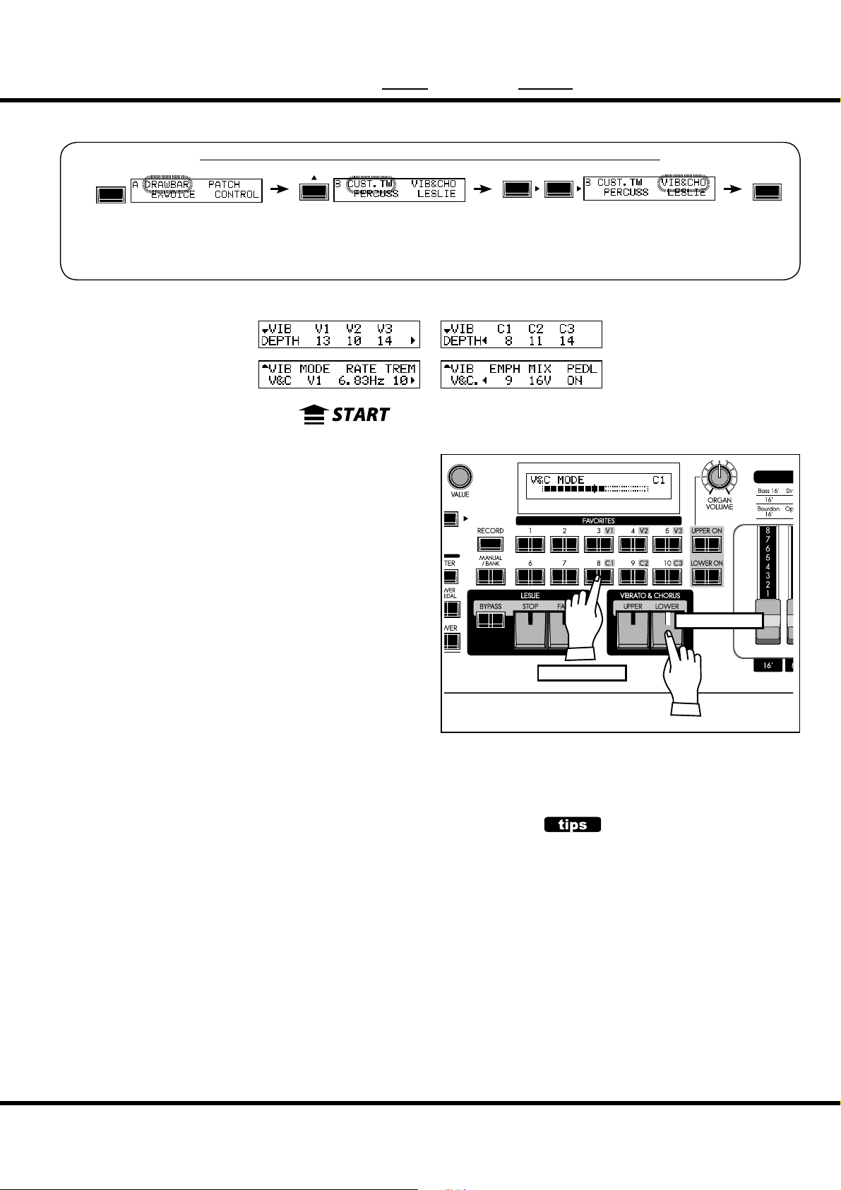
MENU/
❶
❷
❸
❹❹❺❺❻
❼❼❽❽❾
❿❿⓫⓫⓬
EXIT
VIB&CHO ( Vibrato & Chorus)
81
In this mode, the settings speci c to Vibrato and Chorus are adjusted.
To locate this mode:
ENTER
or, keep pressing either of the VIBRATO & CHORUS [UPPER], [LOWER]
buttons for a few seconds.
See “Function mode” (P. 66) for operation details.
❶ MODE
❶
❷
❾
❸
Sets the Mode of the Vibrato and Chorus e ect.
V1 (C1): light vibrato (chorus)
V2 (C2): vibrato (chorus) of standard depth.
V3 (C3): deepest vibrato (chorus)
“Chorus” makes richness to the sound with blending direct and
vibrato tone.
This Mode can be selected on the top panel by holding each
[VIBRATO & CHORUS] button and press [V1] to [C3]button
(right gure).
❷ RATE
Sets the Speed of the Vibrato and Chorus e ect.
e setting range is 6.10 - 7.25 Hz.
❸ VIBRATO - TREMOLO
Sets Tremolo (amplitude modulation) of the Vibrato and Chorus
e ect.
Setting the Vibrato & Chorus Mode
e setting range is 0 - 15.
❹ EMPHASIS
Sets Emphasis (high frequency boost) of the Chorus e ect (C1 / C2 / C3).
e setting range is 0 - 9 dB.
❺ MIX
Sets Mixing ratio of the Chorus e ect (C1 / C2 / C3).
e setting range is D64 (only the Direct tone, no vibrato tone) - EVEN - 63V (only
the Vibrato tone, no direct tone).
❻ PEDAL
Sets Vibrato and Chorus a ects on the Pedal part by [LOWER] button.
e setting range is ON/OFF.
❼ DEPTH V1,❽ DEPTH V2, ❾ DEPTH V3, ❿ DEPTH C1, ⓫ DEPTH C2,⓬ DEPTH C3
Sets the Depth of each Vibrato and Chorus e ect mode.
e setting range is 0 - 15.
⓬
❻
With holding
Press
PEDAL
On the vintage B-3/C-3, the Vibrato and Chorus
a ects not only LOWER part but also PEDAL part
via [LOWER] (exactly, “GREAT”) tablet by the circuit
structure. It is divided on later models.
This parameter simulates that.
NOTE: All the parameters in these modes are
Patch Parameters. They are recorded
into the Patch.
Setting the Parameters
Page 82

82
❶
❷
❸
❹
❺❺❻❻❼
❽❽❾❾❿
⓫
⓬⓬⓭⓭⓮
⓯⓯⓰⓰⓱
⓲
⓳
⓴
LESLIE
In this mode, the settings are made for the built-in Leslie E ect and
the External Leslie Speaker.
ere are many parameters related to the Leslie functions, to make
this easier to edit and use.
To locate this mode:
MENU/
EXIT
or, keep pressing either of the [BYPASS], [STOP], [FAST] buttons for a few seconds.
See “Function mode” (P. 66) for operation details.
⓴
⓲
❸
⓳
❹
⓮
❼
⓱
❿
e built-in Leslie parameters are grouped in macro-settings called
“CABINETS”. You select the CABINET NUMBER in the Combination Presets where this selection is saved as part of the Preset.
ENTER
⓫
❷
❶
CABINET NUMBER
❶ CABINET NUMBER (P)
Selects the Cabinet Number to use in the Patch.
e setting range is P1 to P8 (non-rewritable) and U1 to U8 (rewritable). If the
Leslie parameter is changed, “*” is displayed on the left side.
LESLIE PARAMETERS
❷ CABINET NAME (L)
Sets the Cabinet Name by up to 10 characters.
Move the cursor with the [][] button and select letters with the [VALUE] knob.
e available characters include: Punctuation Marks (space - . ’ &), Numeric Characters (0 - 9), Upper-case Letters (“A - Z”), and Lower-case Letters (“a - z”).
e name and following (L) parameters are not recorded until the Cabinet Macro is
recorded into memory (See the next paragraph.)
❸ AMP (L)
is is for setting the type of the virtual Power Ampli er.
Solid: Solid-state(transistorized) Ampli er
Tub e: Tube Ampli er.
❹ SPEAKER (L)
is is for setting the virtual Speaker.
RotSmall: A small Leslie speaker, such as the Leslie 145
RotLarge: A large Leslie speaker, such as the Leslie 122
Station: A xed speaker, such as the Hammond PR-40
CONCEPT OF THE CABINET NUM-
BER
One Cabinet is equivalent to a virtual Leslie speaker made with the Leslie parameter.
This is a Patch parameter.
#1
#2
#3
Skx
Owner’s Manual
Page 83
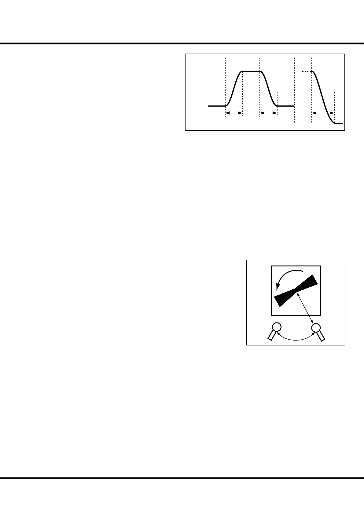
83
❺ SLOW SPEED - HORN (L)
⓬ SLOW SPEED - BASS (L)
Mode:
SLOW FAST SLOW FAST STOP
Sets the speed of the Rotors in Slow mode.
e setting range is 0, 24 to 318 rpm. At 0, no rotation.
❻ FAST SPEED - HORN (L)
⓭ FAST SPEED - BASS (L)
Sets the speed of the Rotors in the Fast mode.
Rotor
Speed:
e setting range is 0, 375 to 453 rpm. At 0, no rotation.
❼ HORN LEVEL (L)
⓮ BASS LEVEL (L)
Sets the volume of the Rotors, Horn and Bass. e setting range is 0 to -12dB.
❽ RISE TIME - HORN (L)
⓯ RISE TIME - BASS (L)
Sets the time for the Rotors to “ramp up” to the “Fast” speed, when switching either
from “Slow” or “Stop” mode.
e setting range for the Horn Rotor is 0.2 to 5.0sec., and the Bass Rotor is 0.5 to
12.5sec.
❾ FALL TIME - HORN (L)
⓰ FALL TIME - BASS (L)
Sets the time for the Rotors to “coast down” to “Slow” speed, when switching from
“Fast” mode.
e setting range for the Horn Rotor is 0.2 to 5.0sec., and that for the Bass Rotor is
0.5 to 12.5sec.
❿ BRAKE TIME - HORN (L)
⓱ BRAKE TIME - BASS (L)
Sets the time for the Rotors to come to a complete “Stop” when switching from
“Fast” mode.
e setting range for the Horn Rotor is 0.2 to 5.0sec., and the Bass Rotor is 0.5 to
12.5sec.
⓫ HORN CHARACTER (L)
Sets the tone of the Horn Rotor.
“FLAT” has no boost or cut in frequencies, and the “MID” or “DEEP” have “peaks”
in various tonal ranges, to mimic the particular characteristics of the horns.
⓲ MIC - ANGLE (L)
e ANGLE and DISTANCE recreates the e ect of two microphones.
e ANGLE sets the distance between the two virtual microphones.
e setting range is 0 to 180°. It is monaural at 0°, or both microphone placed in the
center. Each higher number has e ect of moving the microphones further apart from
each other, resulting in greater stereo separation.
⓳ MIC - DISTANCE (L)
Sets the e ect of setting the microphones at di erent distances from a Leslie Speaker
cabinet, since distance has an e ect on how the Leslie Speaker reproduces through a
sound system.
e setting range is 0.3 to 2.7m (metric measurements). Setting the range “further
away” will result in a less intense sound.
NOTE: After editing, you must record your changes to save them (Procedure following).
Rise
Time
Fall
Time
Brake
Time
Distance
Angle
Setting the Parameters
Page 84
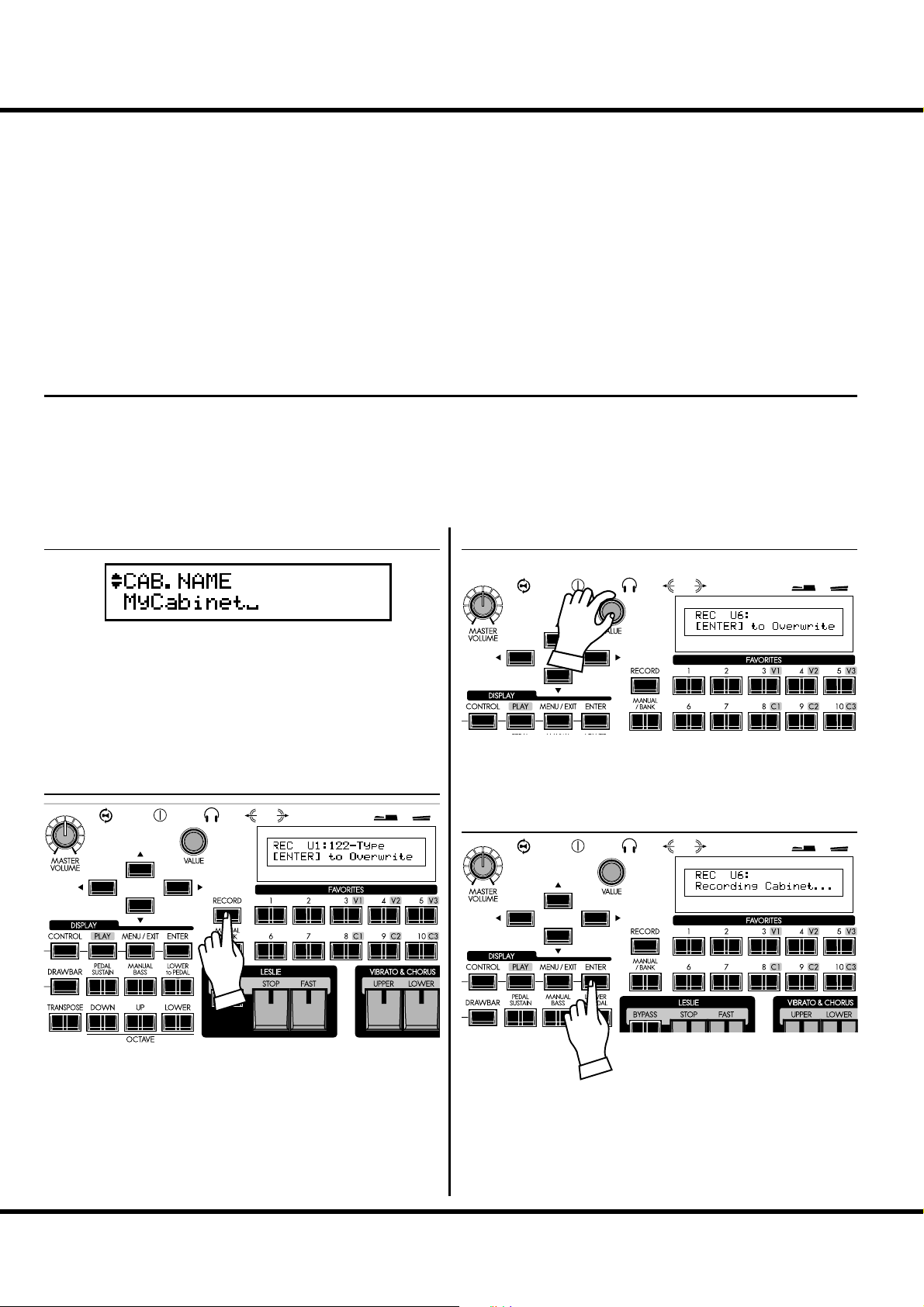
LESLIE - continued
84
EXTERNAL LESLIE SPEAKER
⓴ LESLIE CHANNELS
Sets the channel for the Leslie speaker connected to the LESLIE 11-PIN socket.
1ch: For connecting a 1 channel Leslie cabinet such as the 122XB, 3300/W (non-expansion).
The Drawbar and the Percussion sounds are output only from the rotary channel, the
other voices are from the LINE OUT jack.
3ch: This is for connecting a 3 channel Leslie cabinet such as the 2101/mk2. The Drawbar and
the Percussion sounds are output from the rotary channel, the Extra Voices and bypassed
Drawbar and Percussion sounds are from the stationary channel of the Main and Aux.
NOTE: This is a system parameter. It is recorded upon setting, and is common with all
Patches.
RECORD THE CABINET
Record the Leslie Parameter (#2 to #19 on the previous page) to
the Cabinet Numbers and use them selecting at the Patches.
① ENTER THE NAME
Enter the name to the Cabinet as desired.
② PRESS THE [RECORD]
③ SELECT THE NUMBER TO RECORD
Select the Cabinet Number to record with the [VALUE] knob.
④ PRESS [ENTER] TO DECIDE
Press the [RECORD] button in the Leslie Parameter setting
mode (#2 to #19).
A prompt will appear in the display allowing you to select the
Cabinet you want to record.
Skx
Owner’s Manual
Press [ENTER] to recording the Cabinet.
e display will show the above message during the treatment.
NOTE: If you don’t wish to record, touch the [MENU/EXIT] button.
Page 85

CUST. TW ( Custom Tone-Wheels)
❶
❷
❸
❹
❺❺❻❻❼
❽
In this mode, you select or edit the characteristics of each Tone Wheel set
to be used on the manual keyboards.
To locate this mode:
MENU/
EXIT
See “Function mode” (P. 66) for operation details.
❹
❸
❶
❷
❼
❽
85
ENTER
❶ TONE WHEEL SET
This is for selecting the virtual Tone Wheel set of which
“BType1”, “BType2” and “Mellow” are the Organ Types.
Also, the temporary (= the present setting) automatically
switches to the selected virtual Tone Wheel set just selected
now.
❷ CUSTOM NUMBER
is is for selecting the “CUSTOM NUMBER” to use or compile. e “*” will be displayed when the virtual Tone Wheel
Parameters are changed from this Custom Number.
NOTE: This parameter is a Patch Parameter. It is recorded into each
individual Patch.
❸ CUSTOM NAME
Allows you to name the Custom Tone Wheel using up to 10
character.
Move the cursor using the [] [] buttons and choose the letters using the [VALUE] knob.
e available characters include: Punctuation Marks (space - .
’ &), Numeric Characters (0 - 9), Upper-case Letters (“A - Z”),
and Lower-case Letters (“a - z”).
e name set here, as well as the Tone Wheel Parameters below,
will be deleted, if you do not perform the recording operation
as explained on the next paragraph.
❹ WHEEL NUMBER
Select the Number of the Wheel you want to regulate.
To select the Wheel Number, select the [VALUE] knob here, or
slightly move the footage of the Drawbar while pressing the key
you want to regulate (see the illustration on the right).
When the Wheel Number is selected, each parameter for the
wheel (#5, #6, #7, #8) is displayed.
NOTE: Set the [OCTAVE] and [TRANSPOSE] at “0” for select the cor-
rect wheel number.
INITIAL VALUE OF THE CUSTOM
NUMBER
The typical settings are saved to the Number 1 - 3
(or 4), as the initial value.
For example, to the BType1, “Real B-3” simulating
the well-preserved B-3/C-3 and “80’s Clean” with
less noise, rough sound “Noisy”, and “Noisy 60” with
louder leakage noise is stored.
How to select the WHEEL NUMBER
Setting the Parameters
Page 86
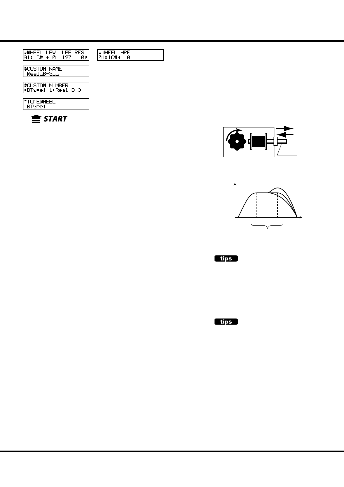
CUST. TW (Custom Tone-Wheels) - continued
❶
❷
❸
❹
❺❺❻❻❼
❽
86
❹
❸
❷
❶
❼
❽
❺ LEVEL
is is for setting the volume of a virtual wheel.
e setting range is -20 to +2dB. If you increase the value, it gets louder.
❻ CUT OFF FREQUENCY - LPF
is is for setting the FREQUENCY to cut the TREBLE of a virtual wheel.
If you increase the value, a leakage noise is heard besides the original Tone Wheel
pitch.
If you decrease the value, the sound gets sweet and mild, as the treble is cut o .
e setting range is 0 - 127.
NOTE: If you decrease the value too low below the fundamental Tone Wheel pitch, the wheel
volume will be reduced.
❼ RESONANCE - LPF
is setting boosts or reduces the level of the Cut O Frequency - LPF (#6).
e setting range is 0 - 127. e higher value boosts treble, and lower values cut
treble smoothly.
❽ CUT OFF FREQUENCY - HPF
is is for setting the FREQUENCY to cut the BASS of this wheel.
If you decrease the value, a motor hum (= noise) is heard besides the original virtual
Tone Wheel sound.
e setting range is 0 - 127.
NOTE: If you increase the value too high above the original Tone Wheel pitch, the sound will
get “Thin”.
NOTE: The parameters 3 - 8 are the virtual Tone Wheel Parameters. If you perform the
recording operation of the next page, it works in common with the same virtual
Tone Wheel set of each Patch.
NOTE: After editing, you must record your changes to save them (Procedure following).
Soft
Loud
Coil
Tone-wheel
Magnet
Concept of the LEVEL ADJUSTMENT
Loudness
Cut Off Frequency
Resonance
HPF LPF
Frequency
LEAKAGE NOISE
In the vintage electro-mechanical Hammond
organs, sometimes the signal from adjacent
Tone Wheels would be picked up (or “leaked”)
along with the current Tone Wheel in play. This
“hash” noise, another Hammond anomaly originally considered to be a defect grew to be an integral
part of the Hammond sound.
“Mellow” does not include the Leakage Noise.
DISTORTION
If you raise the Level and Resonance values too
much, it changes the gain in the sound engine and
may sometimes cause distortion, i.e. unpleasant
noise.
In such a case, please lower these values.
Skx
Owner’s Manual
Page 87

Record the CUSTOM virtual Tone Wheels
e Tone Wheel Parameters (= 3 - 8 of the previous paragraph) are for determining the
Custom Number for recording. e Custom Number is selected and used, when you
play.
① ENTER THE NAME
Enter the Custom Name if desired.
② PRESS THE [RECORD]
Touch the [RECORD] button in the setting mode of the
Tone Wheel Parameters.
e mode for selecting the Custom Number to be recorded will
be displayed.
87
③ SELECT THE NUMBER TO RECORD
④ PRESS [ENTER] TO DECIDE
Select the Custom Number to be recorded using the [VALUE]
knob.
It will be recorded if you touch [ENTER] button.
e display will be as illustrated, while the recording is being
written to memory.
NOTE: If you do not want to record it, just touch the [MENU] button.
Setting the Parameters
Page 88

88
❶
❷
❸
❹
❺
❻
❼
PIPE
In this mode, you edit the characteristics of each Pipe Stop.
To locate this mode:
MENU/
EXIT
See “Function mode” (P. 66) for operation details.
... omitted ...
❶
❶ PIPE STOP
❷
❸
❹
❺
Select the Pipe Stop which you desire to edit using [],[] buttons, or move the
Drawbar which corresponding the Pipe Stop.
ere are 20 Pipe Stops which according to Drawbars from “Bourdon 16´” to “Principal Chorus + Mixture IV” (P. 46).
❷ VOLUME (Pi)
Adjusts the volume of the Pipe Stop. e setting range is 0 to 127.
❸ DETUNE (Pi)
Detunes the pitch of Pipe Stop from accurate pitch by cents ( of semitones).
e setting range is -50 - 0 - +50.
❹ CHIFF (Pi)
Sets the “ Chi ” noise of beginning of notes.
OFF: No chi .
SOFT: Soft chi .
MID: Moderate amount of chi .
LOUD: Maximum amount of chi .
NOTE: The Reed Pipes (Hautbois 8´ and Trompette 8´) are not a ected by this parameter.
❺ CUT OFF FREQUENCY (Pi)
Adjusts the tone quality of the Pipe Stop.
e setting range is -64 to 0. At 0, the full range of sound will be heard. Decreasing
this value will cause tone to become more mellow.
❻ PAN - DIRECTION (Pi)
Adjusts the directionality of the Pipes in order to simulate chamber placement.
e setting range is L64 - C - R63 (Left - Center - Right).
❻
ENTER
❼
DETUNE
The beating is heard by sounding detuned pitch
on sounding accurate pitch.
Generally, they are effect works well if the lower-pitched Pipes are set a “-” value while higherpitched Pipes are set a “+” value. However, it is
strongly recommended that this effect be used
sparingly in order to avoid an unpleasant “out-oftune” e ect.
Skx
Owner’s Manual
Page 89

❼ PAN - IMAGING (Pi)
Sets the arrangement of the Pipes.
FIX: No panning or imaging - All notes sound uniformly.
L-R: Sounds Left to Right which according to the keys.
C
C
D
E
E
F
F
G
G
A
B
R-L: Sounds Right to Left which according to the keys.
C
D
E
E
F
F
G
G
A
B
B
89
PAN AND OUTPUT
The Pipe Stops are extended left to right.
Because of this, you may notice that some
B
C
notes will sound louder than other if only one
LINE OUT is used. To remedy this, set the “Audio Mode - Output” (P. 102 #1) at “MONO”.
This will disable Note Panning and all notes
will sound at equal volume.
PYR: Like the PYRamid, sounds center to sides which according to the keys.
C
C
E
F
G
A
B
INV: Like the INVerted pyramid, sounds sides to center which according to the keys.
C
D
E
F
D
E
F
G
B
C
E
F
G
G
A
B
B
NOTE: The parameters of these modes (Pi)
are Pipe parameters. They are recorded when they are set, and are
common for each Patch.
Setting the Parameters
Page 90

90
❶
❷
❸
❹
⓭
⓯
⓲
⓮
⓰
❺
⓱
⓭
❶
⓲
❺
⓮
OD / EFF ( Overdrive / E ects)
In this mode, Overdrive and the Multi-E ects are adjusted.
e Organ and Extra Voice Sections have their own independent Overdrive and
Multi-E ects section.
To locate this mode:
MENU/
EXIT
or, keep pressing the [OVERDRIVE], [EFFECT ON] buttons for a few seconds.
See “Function mode” (P. 66) for operation details.
❷
⓯
⓰
❸
⓱
❹
ENTER
ORGAN SECTION EFFECTS
OVERDRIVE
❶ OVERDRIVE - DRIVE
Adjusts the overall amount of the Overdrive. e higher the value, more distortion
is obtained. It is linked with the [DRAWBARS OVERDRIVE AMOUNT] knob
on the top panel.
❷ OVERDRIVE - EXPRESSION
Sets response of Overdrive to an Expression Pedal.
EX-OD: Overdrive e ect increases/decreases along with volume.
OD-EX: Overdrive e ect remains constant, Expression Pedal increases/decreases volume.
OD ONLY: Volume remains constant, Expression Pedal increases/decreases the amount of
Overdrive.
INPUT: Expression Pedal attenuates INPUT level to Overdrive e ect. Lesser Volume control.
❸ OVERDRIVE - PREAMP
Sets the characteristic of the Overdrive.
Tub e: Replicates the overdrive of a tube-driven amp.
Stomp: Replicates the stomp box.
Clip: Accurate hard clip.
EPAmp: Replicates the pre-ampli er of an electric piano.
❹ OVERDRIVE - OUTPUT LEVEL
Allows you to balance the Overdrive level with the input level if the two are di erent.
e setting range is 0 to 127.
Level
Time
Skx
Owner’s Manual
Page 91

MULTI-EFFECTS
❺
❻
❼❼❽
❺
❻
❼❼❽
❺ EFFECT TYPE
Selects the Multi-E ect type. e following e ects are built in the SKX.
Tremolo, Auto Pan, Wah-Wah, Ring Mod., Phaser, Flanger, Chorus, Delay
e parameters for the Multi-E ects are di erent type by type. e explanation
about the types follows:
Tremolo
e Tremolo modulates the volume at a set cycle.
❺
❻
❽
91
❻ TREMOLO - WAVEFORM
Sets which waveform is used to modulate the volume.
Tri: Triangle wave. The volume changes smoothly.
Sqr: Square wave. The volume suddenly rises and falls.
Saw: Sawtooth wave. Repeated decaying sound is obtained.
S&H: Sample & hold. The volume changes randomly.
DSqr: Dull square wave like the old electric piano e ect.
❼ TREMOLO - RATE
Adjusts the speed of the tremolo cycle.
e setting range is 0 to 127. e higher the value rises, the faster the cycle.
is is linked with the [EFFECT AMOUNT] knob on the top panel.
❽ TREMOLO - DEPTH
Adjusts the depth of the tremolo e ect.
e setting range is 0 to 127. At 0 the volume does not modulate. e higher the
value, the deeper becomes the e ect. At 127, the sound will alternate between “no
sound” and maximum volume.
Auto Pan
Auto Pan applies adjustable modulation to the stereo eld.
is is not applicable if a monophonic (one channel) amp is used, or when the Leslie
e ect is used.
❺
❻ AUTO PAN - WAVEFORM
Sets which waveform to modulate the direction.
Tri: Triangle wave. The direction smoothly changes.
Sqr: Square wave. The direction suddenly moves to the left, and suddenly moves to the right.
Saw: Sawtooth waveform. The direction repeatedly moves from left to right.
S&H: Sample & hold. The direction changes randomly.
DSqr: Dull square wave like the old electric piano e ect (recommended).
❼ AUTO PAN - RATE
Adjusts the speed of the modulation.
e setting range is 0 to 127. e higher the value, the faster the modulation. It is
linked with the [EFFECT AMOUNT] on the top panel.
❽ AUTO PAN DEPTH
Adjusts the depth of the cycle.
e setting range is 0 to 127. At 0, there is no direction modulation. e higher the
value, the deeper the e ect. At 127 you can give a perfect left/right repetition.
❻
❽
Level
Depth
Rate
Time
Left Right
Rate
Time
Depth
NOTE: All the parameters in these modes are
Patch Parameters. They are recorded
into the Patch.
Setting the Parameters
Page 92
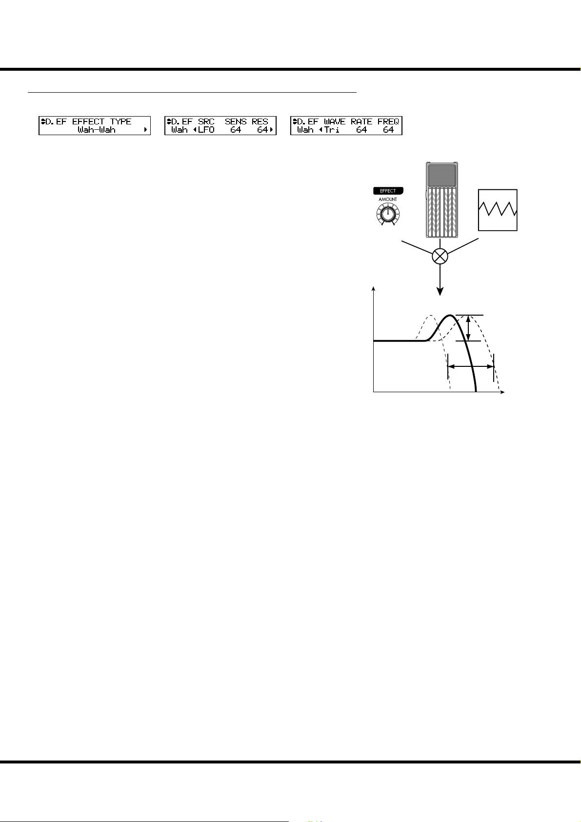
OD / EFF (Overdrive / E ects) - continued
❺
❻
❼❼❽
❾
❿❿⓫
92
Wah-Wah
Wah-Wah imposes a “speech-like” dynamic to the sound.
❺
❻ Wah-Wah - SOURCE
Selects the source of the Wah-Wah control.
MAN: Uses the FREQ parameters, i.e. the [EFFECT AMOUNT] knob.
EXP: Uses the Expression Pedal as a “Wah Wah pedal”.
LFO: Auto-Wah using the built-in ‘LFO - Low Frequency Oscillator’.
❼ Wah-Wah - SENSITIVITY
Sets the sensitivity to change the Wah e ect of the LFO or Expression Pedal.
It is linked with the [EFFECT AMOUNT] knob on the top panel when the
SOURCE (6) is set at EXP.
e setting range is 0 to 127. e dynamic response increases as the value rises.
❽ Wah-Wah RESONANCE
Boosts the cut-o frequency range of the Low-pass Filter and gives a more pronounced “Wah” e ect.
e setting range is 0 to 127. e resonance increases as the value rises.
❾ Wah-Wah - WAVEFORM
When the SOURCE (6) is set at LFO, the LFO wave form is set.
Tri: Triangle wave. The sound smoothly varies.
Sqr: Square wave. The lter suddenly opens and suddenly closes.
Saw: Saw-tooth wave. Repeated changes in the sound are obtained.
S&H: Sample & Hold. Random sound changes are obtained.
❿ Wah-Wah - RATE
When the SOURCE (6) is set at LFO, the cycle speed is adjusted. It is linked with
the [EFFECT AMOUNT] knob on the top panel when the SOURCE (5) is set at
LFO.
e setting range is 0 to 127. e cycle becomes faster as the value increases.
⓫ Wah-Wah - FREQUENCY
Adjusts the central frequency. It is linked with the [EFFECT AMOUNT] knob on
the top panel when the SOURCE (6) is set at MAN.
e setting range is 0 to 127. e frequency becomes higher as the value is increased.
❻
❽
❾
⓫
Level
Waveform,
Rate
Modulation
Source
Resonance
Sensitivity
Frequency
Skx
Owner’s Manual
Page 93

Ring Mod.
❺
❻
❼❼❽
❾
❿❿⓫
e Ring Modulator creates complex, metallic-like sounds by taking the sum and di erence of the fundamental tone and a second “ring” frequency.
❺
❻
❽
❾
⓫
93
❻ RING MODULATOR - SOURCE
Selects which to use to modulate the ring frequency.
MAN: Uses the following FREQ parameter, i. e. the [EFFECT AMOUNT] knob.
EXP: Modulates the ring frequency with the Expression Pedal.
LFO: Allows a cyclical modulation e ect using the built-in LFO-Low Frequency Oscillator.
NOTE: The ring frequency changes by the note, i. d. the UPPER Part performance (or the perfor-
mance of the allocated part if in the Extra Voices).
❼ RING MODULATOR - FREQUENCY
Adjusts the central ring frequency. It is linked with the [EFFECT AMOUNT] knob
on the top panel when the SOURCE (6) is set at MAN, EXP and NOTE.
e setting range is 0 to 127. e frequency becomes higher as the value increases.
❽ RING MODULATOR - MIX
Adjusts the volume balance between the fundamental and e ect sounds.
e setting range is 0 to 127. At 0, only the fundamental sound is heard. As the value
is raised, the more e ect is added. At 127, only the e ect comes out.
❾ RING MODULATOR - WAVEFORM
Selects the LFO waveform when the SOURCE (6) is set at LFO.
Tri: Triangle wave. The ring frequency number smoothly varies.
Sqr: Square wave. The ring sound suddenly changes to treble and also suddenly to bass.
Saw: Sawtooth wave. The ring sound repeatedly drops from treble to bass.
S&H: Sample & hold wave. The ring frequency changes randomly.
❿ RING MODULATOR - RATE
Adjusts the rate of the LFO when SOURCE (6) is set at LFO.
It is linked with the [EFFECT AMOUNT] knob on the top panel when the
SOURCE (6) is set at LFO.
e setting range is 0 to 127. e cycle becomes faster as the value increases.
⓫ RING MODULATOR - DEPTH
Adjusts the depth of the frequency change when the source is set at LFO or EXP.
e setting range is 0 to 127. e ring frequency changes wider as the value increases.
Level
Waveform,
Rate
Modulation
Source
Original Signal
Modulation
Eect Signal
Ring
Frequency
Frequency
Setting the Parameters
Page 94

OD / EFF (Overdrive / E ects) - continued
❺
❻❻❼
❽
❾❾❿❿⓫
94
Phaser
is creates a sound with a shifting phase, adding a twisting e ect to the sound.
❺
❻ PHASER - RATE
❼
❽
Adjusts the frequency speed. It is linked with the [EFFECT AMOUNT] knob.
e setting range is 0 to 127. e cycle becomes faster as the value increases.
❼ PHASER - DEPTH
Adjusts the depth of modulation.
e setting range is 0 to 127. e modulation becomes deeper as the value increases.
❽ PHASER - RESONANCE
Adjusts the resonance (feed-back) amount.
e setting range is 0 to 127. e resonance becomes greater as the value increases.
At higher values, the sound is modulated beyond normal recognition.
❾ PHASER - MANUAL
Sets the middle frequency of the phase e ect.
e setting range is 0 to 127. e frequency becomes higher as the value increases.
❿ PHASER - MIX
Adjusts the volume balance between the “dry” and the e ect sound.
e setting range is 0 to 127. At 0, only “dry” is heard. e e ect level becomes
greater as the value increases. At 127 the ratio between the “dry” and the e ect
sounds becomes 1:1.
⓫ PHASER - HPF
Controls the frequency range of the e ect.
e setting range is 0 to 127. At 0 the e ect is added to all frequencies. e e ect is
added to the higher frequencies as the value increases.
⓫
Level
HPF
Rate
Depth
Mix
Modulation
Manual
eect range
Frequency
Skx
Owner’s Manual
Page 95

Flanger
❾
❺
❻❻❼
❽
❿❿⓫
is is the sweeping “Jet Airplane” sound adjustable from a mild shimmer to a deep
“swoosh”.
❺
❻ FLANGER - RATE
❼
❽
Adjusts the modulation speed. It is linked with the [EFFECT AMOUNT] knob on
the top panel.
e setting range is 0 to 127. e cycle becomes faster as the value increases.
❼ FLANGER - DEPTH
Adjusts the depth of modulation.
e setting range is 0 to 127. e modulation becomes deeper as the value increases.
❽ FLANGER - RESONANCE
Adjusts the amount of resonance (feed-back).
e setting range is 0 to 127. e resonance becomes greater as the value increases.
At higher values, the sound is modulated beyond normal recognition.
❾ FLANGER - DELAY
Controls the delay of the e ect sound.
e setting range is 0 to 127. e delay increases as the value is increased.
❿ FLANGER - MIX
Adjusts the volume balance between the “dry” and the e ect sound.
e setting range is 0 to 127. At 0, only the “dry” is heard. e e ect level becomes
greater as the value is increased. At 127 the ratio between the “dry” and the e ect
sounds becomes 1:1.
⓫ FLANGER - HPF
Controls the frequency range of the e ect.
e setting range is 0 to 127. At 0 the e ect is added to all frequencies. e e ect is
added to the higher frequencies as the value increases.
❾
⓫
Level
95
Rate
Depth
Mix
Modulation
eect range
HPF
Frequency
Setting the Parameters
Page 96
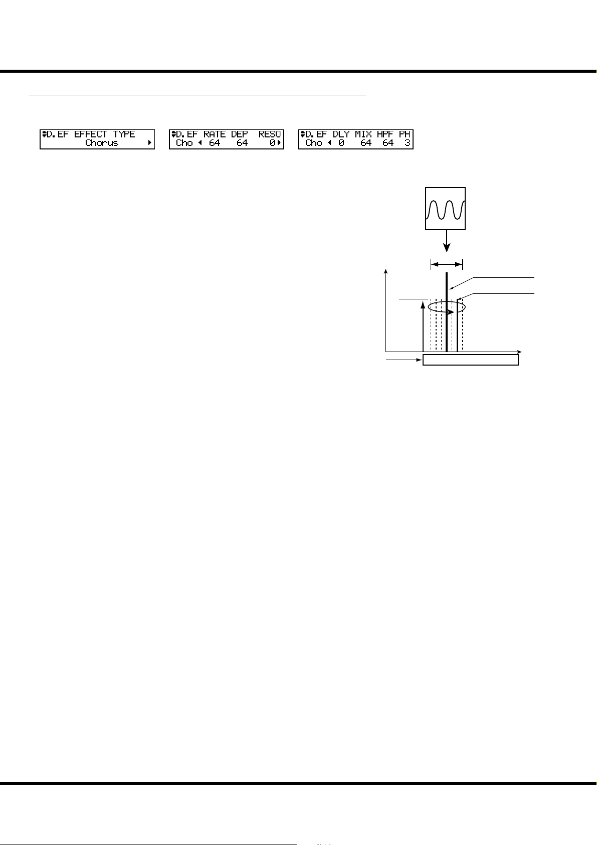
96
❺
❻❻❼❼❽
❾
❿❿⓫⓫⓬
Chorus
is “Chorus” is NOT the same as Hammond’s proprietary “Chorus-Vibrato”. is
e ect is the familiar Chorus as heard widely on electric pianos, guitars, etc.
❺
❻ CHORUS - RATE
Adjusts the speed of the cycle of the rising and falling e ect pitch. It is linked with
the [EFFECT AMOUNT] on the top panel.
e setting rate is 0 to 127. e cycle becomes faster as the value increases.
❼ CHORUS - DEPTH
Adjusts the depth of modulation.
e setting range is 0 to 127. e modulation becomes deeper as the value increases.
❽ CHORUS - RESONANCE
Adjusts the amount of resonance (feed-back).
e setting range is 0 to 127. e resonance becomes greater as the value increases.
At higher values, the sound is modulated beyond normal recognition.
❾ CHORUS - DELAY
Controls the delay of the e ect sound.
e setting range is 0 to 127. e delay becomes greater as the value increases.
❿ CHORUS - MIX
Adjusts the volume balance between the “dry” and the e ect sound.
e setting range is 0 to 127. At 0, only the “dry” is heard. e e ect level becomes
greater as the value increases. At 127 the ratio between the “dry” and the e ect
sounds becomes 1:1.
⓫ CHORUS - HPF
Controls the frequency range of the e ect.
e setting range is 0 to 127. At 0, the e ect is added to all frequencies. e e ect is
added to the higher frequencies as the value increases.
⓬ CHORUS - PHASE
Selects the type of the chorus e ect available:
“2” (normal) or “3” (rich) phase e ect type.
NOTE: There is no phase parameter on the Organ section. And it is xed at “2”.
❽
❾
⓬
Level
Rate
Depth
Original Signal
Eect Signal
Mix
Frequency
eect range
HPF
Skx
Owner’s Manual
Page 97

❺
❻❻❼❼❽
❾
Delay
is is for adding echo e ects.
❺
❻ DELAY - TYPE
Select the type of delay here.
MONO:
A simply delayed sound.
RtoL, LtoR:
The delay is alternated in the stereo eld. At RtoL the delayed sound comes from the right,
and at LtoR from the left. Your results may vary when used in a mono idiom, or through a
Leslie Speaker.
❼ DELAY - TIME
Adjusts the delay time. It is linked with the [EFFECT AMOUNT] on the top panel.
e setting range is 10 to 1000 ms.
❽ DELAY - FEED-BACK
Sets the repetition amount of the e ect sound.
e setting range is 0 to 127. e repetition becomes greater as the value is increased.
❾ DELAY - MIX
Adjusts the volume balance between the “dry” and the e ect sound.
e setting range is 0 to 127. At 0, only the “dry” is heard. e e ect level becomes
greater as the value is increased. At 64 the ratio between the “dry” and the e ect
sounds becomes 1:1. At 127 only the e ect sound is heard.
❽
❾
Level
Delay Time
Level
LR
97
TYPE = MONO
Original Signal
Eect Signal
Mix
Feedback
Time
TYPE = PAN
LR
LR
EFFECTS FOR THE EXTRA VOICE SECTION
OVERDRIVE
⓭ OVERDRIVE - SWITCH
Turns the Overdrive e ect of Extra Voice section “ON/OFF”.
NOTE: While this parameter is “ON”, the stereo sound such as “Stereo Grand” etc. becomes
monaural.
⓮ OVERDRIVE - DRIVE
Controls the distortion amount. e distortion becomes greater as the value is increased.
ere is no knob linked with this e ect, di erent from the Organ section, so the setting is possible only in this mode.
⓯ OVERDRIVE - EXPRESSION
⓰ OVERDRIVE - PREAMP
⓱ OVERDRIVE - OUTPUT LEVEL
e functions of these parameters are the same as those of the Organ section.
Time
OVERDRIVE AND VOLUME
The Overdrive e ect is realized with ampli es the
audio signal. To get the e ect in full, raise the [EXTRA VOICE VOLUME] as possible.
If the sound is too loud by using overdrive e ect,
please let down the OUTPUT LEVEL of the Overdrive.
MULTI-EFFECTS
⓲ EFFECT TYPE
andtheothereffectparameters
e functions of these parameters are the same as those of the Organ section.
NOTE: All the parameters in these modes are
Patch Parameters. They are recorded
into the Patch.
Setting the Parameters
Page 98
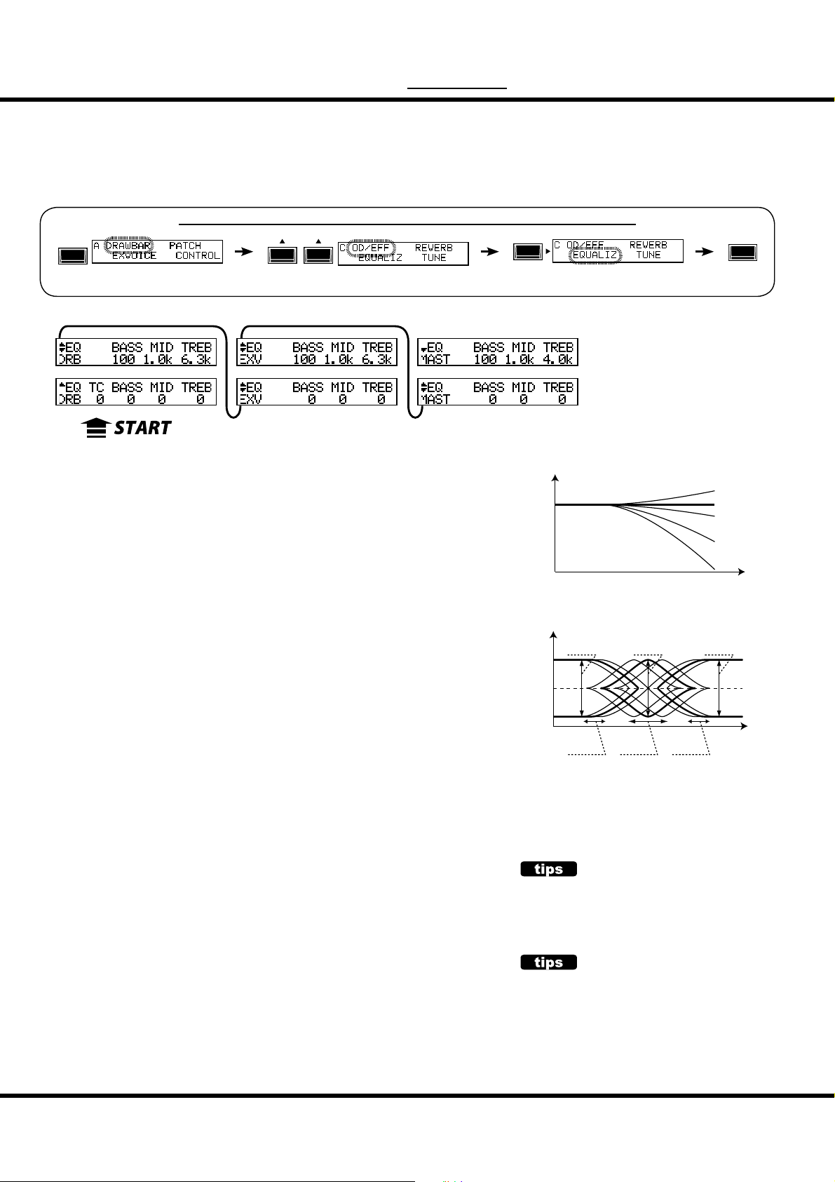
98
❶❶❷❷❸❸❹
❺❺❻❻❼
❽❽❾❾❿
⓫⓫⓬⓬⓭
⓮⓮⓯⓯⓰
⓱⓱⓲⓲⓳
MENU/
EXIT
EQUALIZ ( Equalizer)
In this mode, you adjust the settings for the Equalizer.
An Equalizer is used to adjust the tonal quality. e SKX’s built-in Equalizer consists
of 3 bands and a recreation of the unique “tone” control that was part of the vintage
B-3/C-3. e Bass and Treble bands are handled by “shelf ” equalizers, and the Mid
band is handled by parametric control.
To locate this mode:
ENTER
See “Function mode” (P. 66) for operation details.
❼
❹
⓭
❿
ORGAN SECTION
❶ TONE CONTROL (P)
is is a simulated original B-3/C-3 TONE CONTROL. Its response is unique, but
its basic response is to gently cut the overall treble above 200Hz.
e setting range is -9 to +9, and it becomes neutral when set at “0”. “-1” corresponds to the maximum of the original B-3/C-3 tone control, “-5”, the middle, “-9”,
the minimum. e tone control found on the original B-3/C-3, was only available at
“minus” settings, but here you are able to “plus” the settings as well.
ORGAN SECTION, EXTRA VOICE SECTION, MASTER
❷❽⓮ GAIN - BASS (P) (P) (G)
❸❾⓯ GAIN - MIDDLE (P) (P) (G)
❹❿⓰ GAIN - TREBLE (P) (P) (G)
Adjusts the Boost/Cut of Bass, Mid-range and Treble respectively.
e setting range is -9 to +9. It is at at 0.
❺⓫⓱ FREQUENCY - BASS (P) (P) (G)
❻⓬⓲ FREQUENCY - MIDDLE (P) (P) (G)
❼⓭⓳ FREQUENCY - TREBLE (P) (P) (G)
Adjusts the center frequency (MIDDLE) / turnover frequency (BASS, TREBLE) to
be attenuated.
e setting range is 20Hz - 200Hz for BASS, 250Hz - 3.1kHz for MIDDLE,
4.0kHz - 8.0kHz for TREBLE.
NOTE: The sound may distort if gains are raised too high. Adjust accordingly.
NOTE: The parameter with (P) indicated is a Patch parameter, and is recorded to each Patch.
(G) indicates “Grobal parameter”, which is recorded upon being set, and is common
with each Patch.
⓳
⓰
Gain
+3dB
0dB
-3dB
-9dB
-15dB
Gain
+9dB
0dB
-9dB
The MIDDLE of this equalizer controls a point of frequency. This is called center frequency. The BASS
(or TREBLE) controls lower (or higher) than speci ed frequency. This is called turnover frequency.
100Hz
Diagram of Tone Control
BASS
Gain
BASS
Freq.
20 - 200 4k - 8k
Diagram of 3-bands Equalizer
1kHz 10kHz
MIDDLE
Gain
MIDDLE
Freq.
250 - 3.1k
TREBLE
Freq.
TURNOVER FREQUENCY
TC
+9
0
-1
-5
-9
Frequency
TREBLE
Gain
Frequency
Skx
Owner’s Manual
PATCH PARAMETERS
The equalizer for Organ section and Extra Voice
sections are designed to be a Patch parameter (P)
to be actively utilized as a part of sound making
parameter.
Use the Master Equalizer for tonal compensation
to match the performance stage (G).
Page 99

REVERB
❶
❷
❸❸❹
❺
In this mode, you set the Reverb e ect.
Reverb is common with the Organ and Extra Voice sections, the single reverb control
section a ects both.
To locate this mode:
MENU/
EXIT
or, keep pressing the [REVERB ON] button for a few seconds.
See “Function mode” (P. 66) for operation details.
❶
❶ DEPTH
is sets the depth (volume) of the Reverb E ect.
e setting range is 0 to 127. is parameter is linked with the [REVERB DEPTH]
knob on the top panel.
❷ TYPE
is sets the types of Reverb E ect.
Room 1: Small room
Room 2: Large room
Live: Ambient room
Hall 1: Large Hall
Hall 2: Small Hall
Church: Church
Plate: Iron-plate Reverb
Spring: Spring Reverb
Delay: Delay
PanDly: Panning Delay
RevDly: Reverb + Delay
❸ REVERB TIME
When the Type (#2) is set at Room 1 to Spring, e decay of the Reverb is attenuated.
e setting range is 0 to 127. e decay becomes greater as the value is increased.
❹ DELAY TIME
When the Type (#2) is set at Delay, PanDly, RevDly, this sets the delay time.
e setting range is 4.7 to 2000ms. e delay becomes longer as the number value
is increased.
NOTE: You can set the delay time with the foot switch. (P. 76 #2)
❺ DELAY FEEDBACK
When the Type (#2) is at Delay, PanDly, RevDly, it sets the amount of Feedback
(How many times the sound repeats.)
e setting range is 0 to 96%. e repetition becomes greater as the value is increased.
NOTE: Type (#2) is a micro-parameter. When you change the type, each reverb parameter
(except #1) is automatically set to the recommend value.
❷
❹
❺
99
ENTER
NOTE: All the parameters in these modes are
Patch Parameters. They are recorded
into the Patch.
Setting the Parameters
Page 100
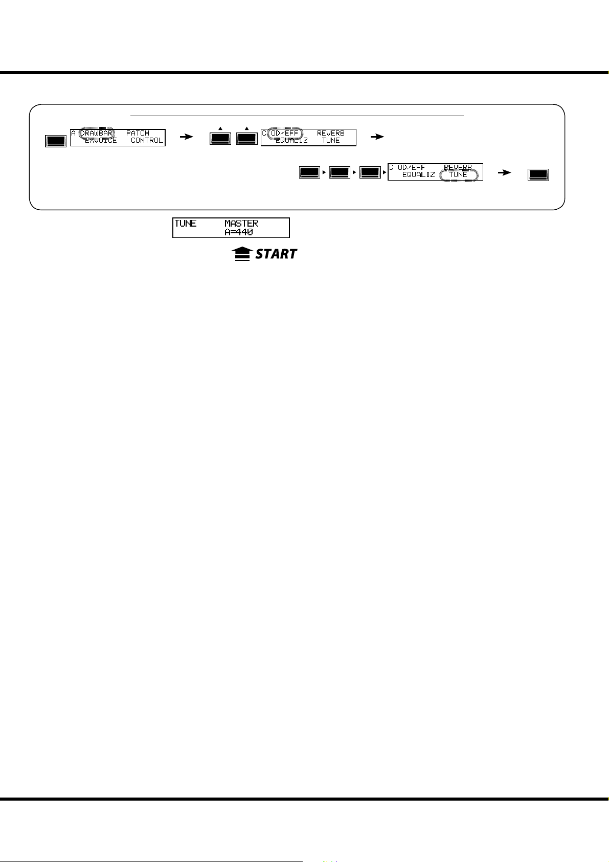
100
❶
In this mode, the entire keyboard is tuned.
To locate this mode:
MENU/
EXIT
See “Function mode” (P. 66) for operation details.
MASTER TUNE
❶ MASTER TUNE
is is for tuning the entire keyboard.
e setting range is A = 430 to 450 Hz.
❶
TUNE
ENTER
NOTE: The parameter of this mode is a Global parameter. It is recorded when it is set, and is
common for each Patch.
Skx
Owner’s Manual
 Loading...