

Page 1

Page 2

Page 3
A SHORT DESCRIPTION OF THE
ELECTRICAL PRINCIPLES AND
TONAL COMBINATIONS OF A
NEW MUSICAL INSTRUMENT
WORLD PATENTED
INDEX TO CONTENTS
Chorus Generator
Diapason Tone Quality
Electrical Principle
Flute Tone Quality
Generator.
Harmonic Controller
Harmonic Controller, Pedal
Organ
Harmonic Controls, Black and
White
Harmonic Controls, Brown
Harmonic’s Seventh
Pipe Organ Mixtures
Pipe Organ Stops
Preset Keys
Preset Pistons (Model E)
Reed Tone Quality
String Tone Quality
Super and Sub-Octave
“Coupler” Effects
..
..
..
..
..
..
..
..
..
..
..
..
..
..
..
..
..
..
Page
9
8,16
18,19
8,16
18
7
10
14
15
14
13
15
5
7
9,16,17
8,16
14
Swell Pedals
Toe Pistons (Model E)
Tone Colours
Tone Colour Combinations
Tone Families
Tone Wheel
Tremulant
ILLUSTRATIONS
AND DIAGRAMS
The Hammond Organ
Plan of Console
Harmonic Controller
Pre-set Pistons (Model E)
Graphs and Wave Patterns
Synchronous Motor and Generator Kit
..
..
..
..
..
..
..
..
..
..
..
..
..
..
Page
12
11
16, 17
17
18
11
4
6
6
6
9
18
Page 4

OUTSTANDING FEATURES
It has the full range of organ tone colours.
Its range of expression is many times greater
than that of other organs.
It occupies only a few square feet of floor
space.
It is ready to play wherever there is an electric
outlet.
It cannot get out of tune, having no reeds nor
pipes.
It is not affected by atmospheric or
temperature conditions.
Its maintenance is negligible.
The standard installation uses about as much
current as four ordinary light bulbs.
Its response and repetition are instantaneous no lag.
It is a beautiful piece of furniture.
It is easily moved,
It is fully guaranteed.
It is made by a well-established organization
with a world-wide reputation for precision
in manufacturing.
Its price is but a fraction of that which any
instrument at all comparable would cost.
But, after all, there is no comparable instru ment.
Page 5

N organ that is without pipes or wind may well
indeed be called a new instrument.
The Hammond Organ, here pictured and described,
is not merely new; it represents in itself a revolution
so far-reaching as to be quite incalculable. New chapters
in our social history were opened when, two or three
generations ago, the telephone and the typewriter
arrived on the scene There can be no doubt whatever
that the advent of this new instrument must have an
equally startling significance in the world of music
Science and the laws of dynamics have been so harnessed
to the inventor's will that he has created an instrument
eminently suitable for the drawing room yet, when
occasion demands, powerful enough to fill a Cathedral
with a tone of great nobility and sweetness It is
remarkably adoptable for installation purposes The
minimum floor space which it needs never exceeds four
or five feet square
The actual "Furniture" of the instrument consists of
but two pieces the console and the power cabinet, which
is connected to the console by a cable and can be placed
in any convenient part of a room or building. The
number of cabinets may be multiplied for
large buildings, as required.
Page Three
Page 6
Page 7
CHAPTER I
T H E T O N A L C O N T R O L S O F
THETHE HAMMOND ORGAN HAMMOND ORGAN
XCEPT where otherwise mentioned, the following
descriptions apply equally to every model of the
Hammond Organ.
Each of the three models, A, B and E, is ideally suitable for its particular
purpose. Models A and B will give every satisfaction in the small church
or auditorium or in the home. There is hardly a limit to the scope of
music which can be played on either of these two instruments.
Model E console represents the ultimate in organ design and can be
termed a professional organist's instrument. Whilst being perfectly
suitable for use in the home or in the smallest or largest building, it is so
equipped that every description of organ literature may be played with a
wealth of dynamic interpretation hitherto unthought of.
It is designed on more ecclesiastical lines than the others, so as to better
harmonise with church appointments. Massive in appearance, it is nearly
as portable as Model B.
GENERAL ARRANGEMENT.
Figure 1 shows the various controls marked. The pre-set keys are at
the left-hand end of each manual. The tremulant control is located just
above the pre-set keys. Immediately over the upper manual are five
groups of controls.
There are two groups of harmonic controls of nine draw-bars each, on
the left-hand side; these operate on the upper manual. The two groups
of nine harmonic controls on the right operate on the lower manual.
Between these groups are two other harmonic controls; these operate
on the pedals.
THE PRE-SET KEYS , Models A and B Consoles (Figure 1).
At the left end of each manual is an additional octave of reverse colour
keys-that is, the naturals are black and the sharps white. These
are the pre-set keys. Those to the left of the lower manual are associated
with that manual, those above with the upper manual.
When a pre-set key is depressed it stays down. When a second key on
the same manual is depressed the first key springs up and the second remains
down. Up, the pre-set key is "off"--not functioning. Depressed,
it is “on.” Only one pre-set key should be depressed on the same manual
at one time.
The key at the extreme left, C, is the cancel key, used only to clear the
pre-set keys when two have been depressed by mistake.
Page Five
Page 8

FIGURE 1. PLAN OF CONSOLE (Model A)
FIGURE 1a.
Model E Console. Manual Pre-set Pistons.
Pedal Piston Indicators. Tremulant Levers
FIGURE 1b.
Expression Pedal Indicators. Chorus
Control. Starting and Running Switches.
FIGURE 2. A HARMONIC CONTROLLER
Page Six
Page 9

The two pre-set keys at the extreme right, A# and B, are really switch
keys. when A# is depressed the organ speaks with whatever tone Colour
is set up on the left one of the two harmonic controllers for that manual.
When B is depressed the organ speaks according to the right hand controller for that manual.
The intervening pre-set keys, C# to A inclusive, are each associated with
a different ready-mixed tone quality set up before the organ is installed.
These keys correspond to the pistons on a pipe organ. They are generally
useful tone qualities. The artist may, however, substitute any other
pre-set quality he prefers for any or all of them by a simple method fully
explained in the operating instructions.
The tone of the organ is changed from one quality to another while playing,
merely by depressing another pre-set key.
The two manuals are really duplicates of each other, each having its own
pre-set keys and two harmonic controllers.
It should be clear from the above that, before playing, the organist must
first depress one of the pre-set keys associated with the manual on which
he is about to play.
THE PRE-SET PISTONS , Model E Console (Figure la)
On the Model E Console, small pistons (numbered 0 to 11) are employed,
instead of the reverse colour keys. A label against each piston indicates
the tone quality associated with it. The piston marked "0" is the cancel
key and Nos. 10 and 11 are available for any tone qualities that may
appeal to the organist by manipulation of the drawbars as explained
below.
THE HARMONIC CONTROLLER (Figure 2).
The Harmonic Controller is the device by which the artist is enabled to
mix the fundamental and any or all of 8 different harmonics in various
proportions. It consists of 9 drawbars. The third drawbar from the
left controls the fundamental. Each of the other drawbars controls a
separate harmonic as shown on the diagram. Each drawbar may be set
at any one of 9 different positions. If pushed all the way in, against
the console, the element it represents is not present in the mixture. It
may be drawn out to 8 different positions. These are marked on the
drawbar and may be read by the artist. Each position represents a different
degree of intensity of the element it controls. When drawn out to position
1, the element it represents will be present in the mixture with minimum
intensity, when drawn out to position 2, with greater intensity, and so on,
up to position 8.
A tone colour is logged by noting the numerical position of the various
drawbars. For instance, the tone set up in the diagram (Figure 2) is known
as tone 23,6444,222. After a tone is so logged it may be made available
again by setting up the harmonic controller to that number.
TONE FAMILIES.
In order to make full use of the Hammond method of tone composition,
the artist should understand the general characteristics of the various
tone families.
The four principal families of organ tones are Flute, Diapason, String
and Reed.
Page Seven
Page 10

FLUTE TONE QUALITY.
The flute tone is a comparatively simple tone. Its harmonic development
is concentrated chiefly on the fundamental and second harmonic overtone,
with occasionally the addition of one or two other harmonics. The
relative proportion of these components varies for the different kinds of
flutes.
Combination 00,3500,000 is a quality like that of the pipe organ stop
“ Flute d’amour."
Combination 00,5200,000 is a dopple flute quality.
Combination 00,5310,000 is a melodia quality.
The quality 00,5000,000 is, of course, also very flute-like in its timbre.
It is a pure fundamental tone, however, without harmonic development
and the musician is cautioned against employing it or any other single
fundamental. Its total lack of harmonic development is both unnatural
and unmusical. For a tone to possess character, it must have some harmonic development, and the player should employ only tone colours containing some such development.
It will be apparent that even in this family, the simplest of the tone families,
there is a large number of variations available to the artist from which he
may choose that particular quality which pleases him most.
DIAPASON TONE QUALITY.
The diapason quality is a foundational tone of the pipe organ. There
are various kinds of diapason qualities. All diapasons have both a strong
fundamental and second harmonic with relatively weak upper harmonic
development. The diapason qualities differ from each other principally
in the number and strength of the upper harmonic overtones.
Combination 00,5521,000 is an example of phonon diapason quality.
Combination 00,5442,420 is an example of violin diapason quality.
In pipe organs, the diapason stops are usually strengthened harmonically
by the addition of mixtures or harmonic corroborating tones. The socalled Diapason Chorus" consists of several diapason tones, plus a
group of mixture tones.
Combination 24,6777,664 is an example of diapason chorus quality.
Combination 54,6444,222 is an example of such a quality with 16 foot
diapason.
STRING TONE QUALITY.
String quality is characterized by large upper harmonic development.
The fundamental and second harmonic development are relatively small.
A keen string quality will have very little fundamental and not much second
harmonic. A string quality always has a complete upper harmonic series
present, none of which is unduly strong or weak.
Combination 00,4345,555 is a moderate string quality.
Combination 00,2345,555 is a keen string quality.
Page Eight
Page 11

REED TONE QUALITY.
The characteristic of a reed tone is its very heavy upper harmonic development. Whereas in a diapason quality the upper harmonic development
is only moderate compared to the fundamental and second harmonic,
in a reed chorus the upper harmonic development can he as great as the
fundamental and second harmonic.
Combination, 77,7777,777 is a chorus reed quality with strong sub-octave
or 16 foot tone.
Combination 00,7777,665 is a milder reed chorus.
Combination 35,4687,865 is an example of a very strident reed of the
trumpet quality.
The above are examples of chorus reed tones. Solo Reeds, as their name
implies, are most effective when played as single notes for solo passages.
Some examples of solo reed tones are:
Combination 00,6270,520, a clarinet quality (note large third harmonic).
Combination 00,3675,210 is an organ oboe quality.
Figure 3. Graphs of the wave patterns of string and reed, pitch “A.”
NEW TONE QUALITIES.
Besides the flute, diapason, string and reed tones, the Hammond Organ
can produce countless tones that have never been heard before in a classical
instrument.
In the Hammond Organ any harmonic may be developed independently
of the other harmonics. Also, any harmonic may be entirely suppressed.
Thus, its tonal possibilities are not limited as are those of musical instruments heretofore developed. For instance, tones are available in which
even the fundamental is entirely absent. It is these unfamiliar harmonic
absences which make new such combinations as 00,0261,111 or 00,1426,030.
There are an endless variety of these unfamiliar tone qualities and the
performer must use his own discretion in employing them. While they
may effectively be adapted to certain modern music they are not all suitable
for classical organ literature.
"CHORUS GENERATOR ."
An additional feature now obtainable on Models B and E consoles is
that known as the "Chorus Generator." This imparts a new and
extraordinary richness and beauty, instantly noticeable even to the
untrained ear.
Page Nine
Page 12

A Chorus Control drawbar is provided whereby the organist can turn
this new effect on or off at will.
The Chorus Generator makes possible a large number of pleasing ensemble
qualities. The familiar Voix Celeste and Unda Maris are two of many
useful organ stops which utilize the same principle involved in the
Hammond Organ chorus effect. String combinations, both solo and ensemble, assume a new depth and beauty. Hitherto, it has been customary
to limit such an effect to one or two tonalities. In the Hammond Organ,
the chorus effect may be on any or all tone qualities. The tremulant
takes on a new charm when used with the chorus effect. When the full
organ is used, an added richness and fulness of tone will be instantly
observed: an effect of tone emanating from many sources.
The Chorus Generator has been so designed that combinations of a
dignified character, such as Diapasons and large scale Flutes are not affected
to the extent of the string and reed qualities.
Installation problems will be materially reduced, for the Chorus Effect
does much to overcome the disadvantages of smaller rooms or those
presenting a "dead" or non-reverberating condition.
The Chorus Generator Unit has its own starting and running motors
which operate simultaneously with the motors of the main generator.
For each of certain tone-wheels in the main generator there is in the chorus
generator a pair of tone-wheels which have their speeds so adjusted that
one will produce a tone slightly sharp and the other a tone slightly fiat
by comparison with the accurately tuned main generator frequencies.
Thus, when the chorus generator unit is turned on and a single frequency
sounded from the main generator, the two slightly de-tuned chorus frequencies will also sound and the result is the formation of a complex series
of" beats " or " waves " in the tone.
The chorus control is a black drawbar situated at the right of the console
lust above the end of the harmonic controllers. When the chorus control
is drawn out, the chorus generator unit is switched on. Pushing the
control in disconnects the generator unit so that the chorus effect is not
heard.
GENERAL.
The above should serve to give the artist an idea of the vast resources of
the Hammond Organ. Within each tone family can be discovered an
infinite variety of qualities from which the player can choose; he is
not limited to relatively few in each family, but is enabled to create that
special subtlety of tone-colour which he may want at a particular moment.
It is this which makes the Hammond Organ the instrument upon which
the artist-organist can best express his own individuality.
THE HARMONIC CONTROLLER FOR THE PEDAL ORGAN.
Here the harmonic resources have been combined into only two harmonic
controls. The fundamental 16 ft. pitch and second harmonic are
associated with the left-hand control and produce the fundamental depth
to the pedal. The third, fourth, fifth, sixth and eighth harmonics are
associated with the right-hand control to give higher harmonic quality
variations, and a useful 8 ft. solo if used without the left-hand control.
Page Ten
Page 13

While the possible number of pedal organ tone qualities is, of course, less
than those available on the manuals, the player will find the volume quality
and tonal depth ample to balance any manual combinations that are used.
THE TOE PISTONS , Model E Console (Figure 4).
Situated to the left of the expression pedals of the Model B Console are
four pistons which are placed in the correct position for easy manipulalation for the toe.
The standard settings are:
1. FF Full 16 ft., 8 ft. and mixtures.
2. MF Diapason 16 ft., String 8 ft., Flute 8 ft.
3. Great to Pedal 8 ft.
(This piston is especially useful as it enables the organist to couple
any of the whole range of tone qualities available on the manuals to
the pedals in 8 ft. pitch: 16 ft. tone can be added by using the
first pedal drawbar).
4. Adjustable. With this piston the two pedal drawbars are brought
into action and are used in the manner described in the foregoing
paragraph.
Electrically lighted indicators just above the manuals show which of the
toe pistons is in action.
Figure 4 illustrates the position of these toe pistons, the independent
swell pedals (see page 12) and also the 32-note concave, radiating pedal
clavier that is such an outstanding feature of the Model E.
FIGURE 4
THE TREMULANT.
The organist can adjust the degree of tremulant to suit his own musical
taste. When the knob is turned as far as possible to the left, the tremulant
is entirely off. As it is turned to the right (clockwise direction), the degree
of tremulant gradually increases until it reaches the maximum at the extreme
right position. The white dot marker on the knob indicates at a glance
the degree of tremulant present.
The adjustable feature makes it possible to have a mild tremulant for flute
qualities and a more vibrant one for string qualities, etc.
The Model E Console has separate tremulants for each manual. These
tremulants are adjustable as to intensity or amplitude.
Page Eleven
Page 14

THE SWELL PEDAL, Models A and B.
The swell pedal, or expression pedal, is located in the customary position
and with it the volume of the organ may be controlled over a wide range.
It operates on the two manuals and pedal clavier equally; that is to say,
once the manuals and pedals are balanced, they retain their relative balance
over the entire swell pedal range.
The dynamic range of the swell unit is stupendous. Technically, the power
ratio of the swell pedal fully open to fully closed, is 50 decibels. In the
most carefully constructed pipe organ swell shades, the power ratio seldom
exceeds 15 decibels and is usually considerably less. The range of 50
decibels would correspond to approximately 32 points on a pipe organ,
only a very few of which are constructed with a range in excess of 12
points.
The volume increase effected through the swell pedal is dynamically
equivalent to a pipe organ crescendo build-up. One noticeable and
very desirable difference is the absence of sudden tone quality changes
characteristic of the build-up of the pipe organ to orchestral crescendos.
HOW TO MAKE ONE MANUAL LOUDER THAN THE OTHER
Models A and B.
Since the swell pedal operates equally on both manuals and on the pedals,
this balance is maintained throughout the entire dynamic range of the swell
unit. When it is desired to make one manual louder than the other, it is
necessary only to select a tone colour which is softer than the one being
used on the other manual, whether the softer tone colour be identical in
character or different.
To select an identical but softer tone colour, it is necessary only to see that
the harmonic controller for that manual is set with the drawbars in the
same relationship to each other, but not pulled out so far. For example,
tone number 23,6444,222 is of the same quality as 34,7555,333, but softer.
You have simply pushed each drawbar in by one position.
This ability to make the same tone colour louder or softer on one manual
than on the other is of great advantage musically. The swell pedal,
operating equally on both manuals changes the volume of both equally
without destroying the balance between them.
The volume of the pedals can be controlled over quite a wide range by
the use of the harmonic controls associated with the pedals, in addition
to the volume change of the swell pedal.
THE SWELL PEDALS , Model E (Figure 4).
The Model E Console has the added advantage of ind~pendent swell
pedals, each of which affects its respective manual over the wide dynamic
range for which the Hammond Organ is noted. The pedal controlling
the Great manual also controls the pedal clavier.
The position of each pedal at any time is clearly shown by indicators
situated on the right, above the upper manual (Figure lb).
Page Twelve
Page 15

CHAPTER II.
ANALOGY BETWEEN HARMONICS AND PIPE
ORGAN MIXTURES.
HOSE familiar with pipe organ design will recognise that the har monic control system of the Hammond Organ is simply an extension
of the principle of harmonic corroborating stops or mixture stops
on a pipe organ.
In pipe organ phraseology, the fundamental is of 8-foot pitch, the second
harmonic of 4-foot pitch, the third harmonic of 2 2/3-foot pitch (twelfth or
nazard), the fourth harmonic of 2-foot pitch (fifteenth or super octave),
the fifth harmonic of 1 2/5-foot pitch (seventeenth or tierce), the sixth
harmonic of 1 1/3-foot pitch (nineteenth or larigot), the eighth harmonic of
1-foot pitch (third octave or twenty-second), the sub-harmonic of 16-foot
pitch, and third sub-harmonic of 5 1/3-foot pitch.
The chief difference is that in the Hammond Organ the player is able to
control the precise amount of strength of each rank, which is obviously
impossible with pipes, because a pipe must either be blown or left silent.
To incorporate as many different sizes of pipes for each rank of the harmonic
series as are necessary to control the tone quality by harmonic changes
alone, would require so many pipes that the expense and difficulty of
regulation and maintenance would make it impracticable. The number of
pipes required under such a system would be so large that it is actually
simpler, and requires fewer pipes, to put the harmonics in the foundation
pipes by voicing, and to supply as many ranks of differently voiced pipes
as the user wants or can pay for.
THE HAMMOND ORGAN IS A "STRAIGHT" ORGAN.
Without going into any discussion as to the merits of "extension" in a
pipe organ, it is obvious that this principle cannot be used to reduce the
number of pipes which would be necessary to control the tone quality by
harmonic pipes alone; for in the common case where the same frequency
reappears twice as a harmonic of different order of two notes in one chord,
the single pipe would have to be made to blow twice as hard. This is
plainly impossible because the pipe must either be blown the same way
or not blown at all.
Owing to the fact that it is much simpler to control the amount of electricity
which will flow in an electric circuit than it is to control the amount of
sound that will come from a pipe, it has been possible to design the instrument so that one source of a given frequency can be used to put different
amounts of electric current into the whole. No matter how many times
a certain frequency is called upon to enter into a complex mixture of a
chord of tones of one kind, the same source can be used with increasing
strength and so represents in itself a large number of pipes which would
otherwise have to be available for the purpose. Thus, the Hammond
Organ has none of the tonal failings characteristic of the unit pipe organ.
It is a straight organ with full and equal tonal resources available on both
manuals and pedals.
Page Thirteen
Page 16

SEVENTH HARMONIC OMITTED.
The seventh harmonic is not represented on account of tempered scale
interference. This harmonic is always eliminated as much as possible
in the design and building of musical instruments employing the tempered
scale.
SUPER AND SUB-OCTAVE "COUPLER" EFFECTS.
Pipe and reed organs are usually equipped with super and sub-octave
couplers. The chief function of a super-octave is to introduce a large
second harmonic (octave pitch) into the tone quality. The sub-octave
coupler introduces a large sub-fundamental into the tone quality. On
the Hammond Organ these harmonics are readily introduced with the
appropriate draw bars.
THE BLACK AND WHITE SERIES OF HARMONIC CONTROLS.
In each group of nine controls, the two left ones are coloured brown,
while those to the right are either black or white. In the black and white
series, the white one on the left is the fundamental of the corresponding
note on the manual it controls. The next draw bar to the right controls
the second harmonic. The second harmonic is an octave higher in pitch
than that of the fundamental. If the fundamental be thought of as "doh"
in the scale doh, ray, me-then the second harmonic is also "doh" one
octave up. It is coloured white, like the fundamental, and it will be
found that every white draw bar is also a " doh "either one, two or three
octaves up.
The fifth draw bar from the left controls the third harmonic and is coloured
black. The third harmonic tone is "soh." The seventh draw bar from
the left, controlling the fifth harmonic, is black and is a" me." The eighth
draw bar from the left, controlling the sixth harmonic, is black and is
a soh."
MUSICAL SIGNIFICANCE OF BLACK AND WHITE SERIES.
The black and white harmonic series has a very real musical significance.
The harmonics associated with the white draw bars are all of octave relations. When playing a chord, for instance, the introduction of these
harmonics does not in any way change the concordance of the musical
effect. The effect is one of coupling the first, second, and third octaves
to various degrees of strength. The change in tone colour brought about
by changing from one white draw bar to four white draw bars is analogous
to the difference between a single note and a double~octave of that note.
The tonal brilliance is greatly increased, but the general effect of consonance
is the same.
The introduction of the harmonic pitches associated with the black draw
bars brings about a dissonant effect. For instance, supposing we are
playing the triad C-E-G with only the white draw bars out. All pitches
involved will then be either C, E, or G.
Now let us introduce the third harmonic which is the first in the black
series. It introduces the pitches G, B and D one octave up. B and D
are obviously" dissonant." Now suppose we draw the black fifth harmonic
control. It introduces the pitches E, G# and B two octaves up. G#
and B are dissonant. The black sixth harmonic draw bar introduces
G, B and D two octaves up. B and D are dissonant. The purpose of
this illustration is to show the dissonant effect produced by the black series.
It must not be concluded, however, that the draw bars of the black series
Page Fourteen
Page 17

are unmusical. The mellowness of a horn, the pungency of strings, and
the brilliant and strident tone of reeds are all traceable to harmonics of
pitches other than octaves together with those of octave pitches.
BLACK SERIES SHOULD NOT BE STRONGER THAN WHITE.
However, the black series should not be of strengths larger compared with
the white series. The reader will understand that the combination
00,1282,882 will have so many strong dissonant pitches in it that when
playing a chord the effect will be so discordant that the listener will not
even know what notes are being played. In order that the effect be musical
and consonant, the black series should be employed as sparingly as possible.
If a black draw bar is employed, it is a good rule to draw the adjacent white
draw bars to strengths within two steps of the black.
NO SINGLE HARMONIC PROMINENT.
It is not true in general that the prominence of any single harmonic
necessarily characterizes a given tone quality. For instance, the combination 00,5484,211 is of a mild reed quality. when played as a solo, the effect
is musically satisfactory. However, when this combination is used in
playing chords particularly below middle C) the dissonance caused by the
large third harmonic makes it unsuitable. If this combination is changed
to 00,5575,211 (increasing the adjacent white draw bars by one step and
decreasing the black draw bar by one step) the quality as a solo will remain
for all intents and purposes the same. Only on a quick switch-over test
can any difference be detected in quality. However, when playing chords,
the dissonance is considerably reduced. Supposing the combination is
further altered by increasing the adjacent white draw bars by one more
step and decreasing the black draw bar by one more step: the combination
here becomes 00,56,211. The original solo character is still maintained.
The objectionable dissonance, however, is now entirely removed, making
the quality useful both for solo and ensemble purposes. From this
illustration one learns that the quality or timbre of a musical sound is
determined more by the general distribution of energy over the harmonics
than by the concentration of energy on any one harmonic. The player
who will select combination numbers in which the black draw bar numbers
are not too prominent will always find the musical results satisfactory.
THE BROWN HARMONIC CONTROLS.
In addition to the black and white series of controls, there are two brown
controls on the left of each group. These are used to produce combinations of sub-octave tonality comparable to the addition of 16-ft. stops in
a pipe organ. The control on the left is the sub-octave of the fundamental
and is of pitch "doh" and thus can be treated like one of the white series.
The right brown control is the third harmonic of the sub-octave and is
of "soh" pitch and this should be treated like one of the black series of
draw bars.
HARMONIC CONTROLS UNLIKE PIPE ORGAN STOPS.
It is essential not to confuse the harmonic controls of the Hammond Organ
with the stops of a pipe organ. They are not at all the same. No single
control produces more of a flute or more of a string tone than any other.
The flute may be produced by a certain combination of controls, the strings
by another combination, or both flute and strings may be played by still a
different combination.
Page Fifteen
Page 18

CHAPTER III.
A FEW INTERESTING TONE COLOURS.
HE following is a list of tone combinations and effects which have
been found pleasing to many musicians. The organist is urged
to explore the tonal possibilities of his instrument, and work out
those combinations which not only satisfy his own taste but suit the
acoustical environment in which the organ may be placed.
For example, the oboe combination given below may not at all fit the player's
particular concept of what that tone-colour should be; and it may be
affected by the acoustical surroundings. If, however, the organist takes
this log number" as a point of departure, and experiments with itperhaps intensifying some of the harmonics a little, perhaps repressing
others-he will soon discover the particular tone he prefers.
Here are a few starting points for a voyage of discovery:
FLUTES. DIAPASONS.
Gedeckt Aetheria
Holi Flute
Orchestral Flute
Wald Flute
Stopped Flute
Clarabella
Doppel Flute
Concert Flute
Melodia
Gross Flute
Flute l’amour
Tibia
Tibia with 16
..
..
..
..
..
..
..
..
..
..
..
..
..
00,3000,000
00,3100,000
00,3811,000
00,4700,000
00,7030,000
00,5210,000
00,6100,000
00,6300,000
00,2311,000
00,8321,000
00,5020,000
00,8760,000
71,7721,000
2nd Open Diapason
3rd Open Diapason
Geigen Diapason
Horn Diapason
Phonon Diapason
Bell Diapason
Violin Diapason
..
..
..
..
..
..
..
00,6633,200
00,4432,100
00,4413,110
00,6731,110
00,7753,111
00,5745,100
00,5442,200
STRINGS. REEDS.
Aeoline
“
Dulciana
Quintadena
Gemshorn
Violin
“
“ (solo)
Cello
“
“
..
..
..
..
..
..
..
..
..
..
..
00,2221,100
00,3322,000
00,3221,000
00,0320,000
00,3421,100
00,4645,320
00,1455,542
00,2434,332
00,2645,400
00,0577,542
00,0455,411
English Horn
Clarinet
Sarusophone
Vox Humana
“ ” (Wooden)
French Horn
Corno l’amour
Bassoon
“ ”
Fagotte
Muted Horn
Clarion
Trumpet
“ ”
Tuba
Saxophone
Bass Horn
..
..
..
..
..
..
..
..
..
..
..
..
..
..
..
..
..
00,2574,310
00,6070,330
00,2380,330
00,1200,432
00,0564,000
00,7522,000
00,6751,000
08,8000,000
00,2484,321
00,3630,000
00,3760,000
00,4567,000
00,5674,000
00,4666,400
00,8887,500
01,8761,210
75,8410,000
Page Sixteen
Page 19

TONE COLOUR COMBINATIONS.
Soft Accompanying
Flutes
Flutes, 8' with soft
4'
Flutes, 8' and 4'
Soft Flute, 8' with 4'
Flutes, 8', 4' and 2'
Oboe and Flute
16' with dolce
mixture
Soft Strings
“ ”
“ ”
“ ”
Keen Strings
“ ”
..
..
..
..
..
..
..
..
..
..
..
..
..
..
00,2220,000
00,4321,000
00,5201,000
00,8524,000
00,3512,000
00,7615,113
00,4555,430
50,2001,110
00,1233,333
00,0111,111
01,1333,210
00,2434,332
00,1455,542
00,0343,333
Strings with 16'
Flutes and Strings
Soft Flutes and
Strings
Very Soft Full Swell
with 16'
A Full Solo Com bination
Full, reedy swell
A Diapason Chorus
with 16'
Diapasons
Soft Diapason with
4' principal
A Full Swell Com bination
..
..
..
..
..
..
..
..
..
..
..
..
13,8545,430
00,4535,222
00,2321,021
21,2212,110
27,2225,220
14,5645,553
22,8865,421
00,8877,532
00,6503,020
00,7764,321
Below is given a small list of further tone-combinations which may be
found pleasing, according to taste. They are merely representative;
there are thousands more of each type and the artist will, no doubt, make
many discoveries and experiment with those that best suit his purpose.
Flute Harmonique
Flutes 16 ft. and 4 ft.
Oboe
Clarinet
English Horn
French Horn
Trumpet
Solo Violin
Violin Diapason
Soft Strings
..
..
..
..
..
..
..
..
..
..
00,6500,000
62,5720,000
00,3675,210
00,6470,520
00,1355,430
00,7431,000
01,4765,530
00,3335,331
00,4413,110
01,2221,300
Open Diapason
Salicional
Soft Swell with Dolce
Cornet
Full Swell
Diapason Chorus with
Mixtures
Full Organ
Soft Flute
Medium Flute
..
..
..
..
..
..
..
..
..
..
00,7755,220
01,4433,220
14,5645,553
00,4222,111
01,5656,342
67,7778,677
00,3210,000
00,5220,000
According to the order received-whether for church or home use-a
nicely-balanced settings which in our opinion is appropriate for each
purpose, is provided on the organ as it leaves the factory, but the owner
may either call upon us to re-voice any tonal combination when installed
or, with a few moments' instruction, be capable of so doing himself.
Page Seventeen
Page 20

CHAPTER IV.
THE ELECTRICAL PRINCIPLE
OF THE HAMMOND ORGAN
HOW MUSICAL TONES ARE CREATED.
HEN you pull out one drawbar of a controller and depress a playing
key, a minute single alternating current generated in the console
is carried through the cable to the power cabinet. Here it is
amplified by the use of normal amplifying methods and caused to operate
standard speaker cones and produce audible sound. The characteristics
of the minute current generated are such that the sound produced at the
speakers is a musical tone perfect in pitch and free from all overtones and
harmonics. In other words, it is a pure fundamental tone.
To this the artist, by using the other drawbars may add other pure tones
which are selected harmonics of this fundamental and thus produce
complex musical tones of a wide variety of qualities. The quality of a
musical tone depends upon its harmonic content. This harmonic content
is added to the fundamental by combining the proper minute electrical
currents at the console through use of the controls provided.
THE GENERATOR.
Let us now consider the generator, located in the console, and see how it
produces the minute electrical currents which create the musical tones.
Refer to Figure 5. A metallic plate (the Tone wheel) about the size of
half-a-crown is arranged so that it will rotate in close proximity to a
permanent magnet. About the permanent magnet is wound a coil. The
illustration clearly shows this arrangement of plate, magnet and coil.
This plate is not circular but has a number of high points equally spaced
around its periphery, as shown. As it rotates it does not touch the permanent magnet, but these high points pass close to the magnet. Each
time a high point passes the magnet it varies the magnetic field and
induces a minute flow of current in the coil. Should the tone wheel
be rotated at such a speed, for instance, that 439 high points pass the magnet
each second, a minute
alternating current of a
frequency of 439 would be
generated in the coil and
flow in the circuit with
which it is associated.
Such a frequency of 439
when converted into sound
would be "New Phillharmonic" Pitch "A."
Now in the generator there
are 91 such plates, all permanetly geared together
Page Eighteen
Page 21

and driven by a constant speed synchronous motor. Their speeds
of rotation and the number of high points on each are so calculated
that each disc produces one of the 91 frequencies necessary for the 91
pitches which are used in the fundamentals and harmonic overtones.
THE GENERAL ELECTRICAL OPERATION.
Ninety-one frequencies are thus continuously available at the generator.
when a key is depressed it selects the proper frequency for the fundamental
of the note it represents, together with the proper frequencies for eight
harmonics of that note as set up on the harmonic controller or on a pre-set
key. These frequencies then flow through the contacts made by the key,
each to its proper drawbar, of the harmonic controller. The position of
the drawbar (which is under the control of the artist) determines the
intensity of each frequency. After leaving the harmonic controller these
various frequencies are superimposed upon one another, or mixed, and
flow as a single complex electrical wave to the pre-amplifier, also located
in the console. From here the wave (amplified somewhat) flows through
the connecting cable to the amplifiers located in the power cabinet where
it is further amplified and caused to operate the speakers.
The swell pedal control is located between the pre-amplifier and the power
cabinet. Its operation varies the strength of the electric wave flowing
to the power cabinet but does not change any of its other characteristics.
Varying the strength of this wave varies the volume of the organ.
Notice that the operation is entirely electrical. No sound is created in
the console-only electrical wave forms. The music first appears as
sound at the power cabinet.
Page Nineteen
Page 22

SIZES AND WEIGHTS OF
THE HAMMOND ORGAN
HE sizes and weights of the Hammond Organ Consoles
given below will, in themselves, explain the remarkable
adaptability of the instrument in the matter of installation and the small space occupied.
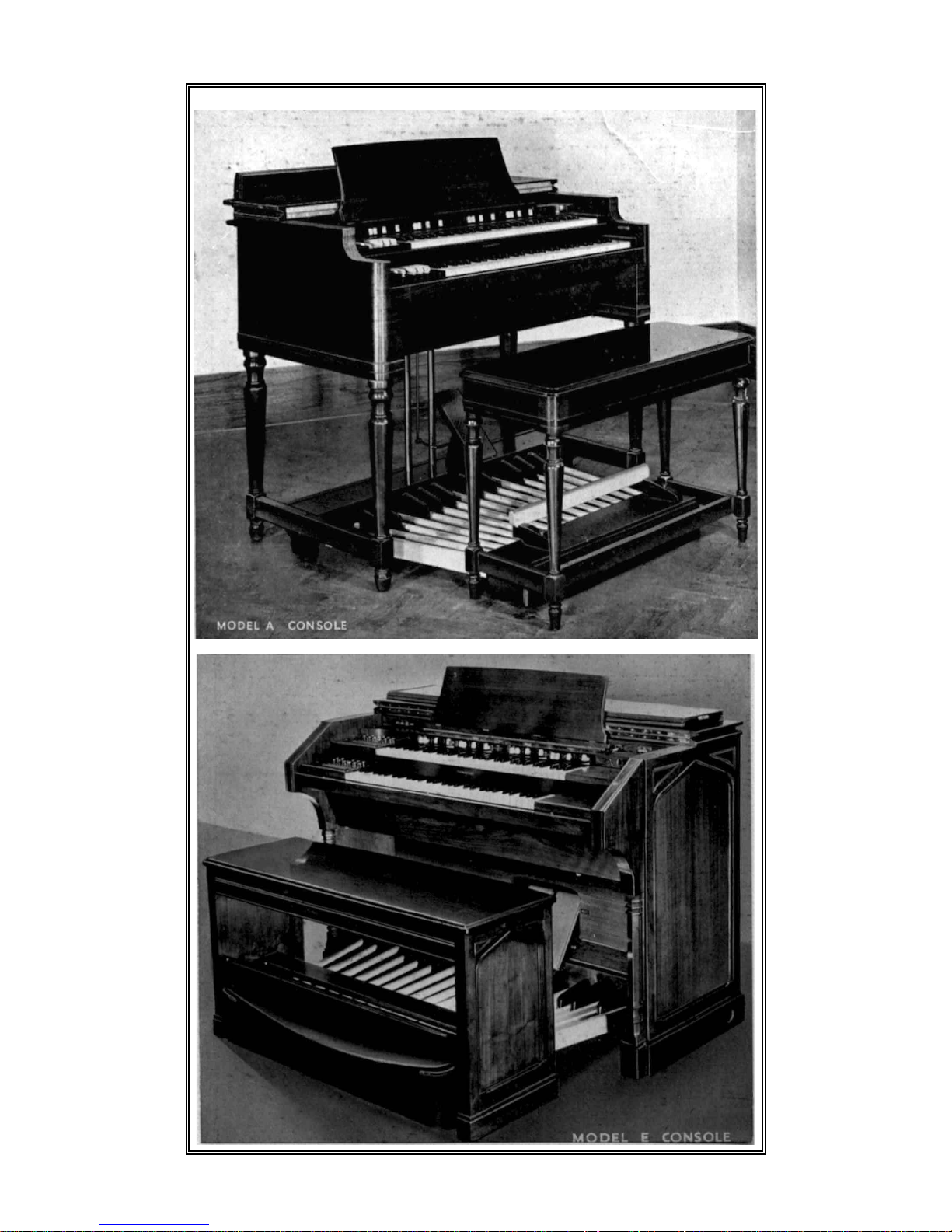
MODEL A CONSOLE
Dimensions: Length, 48" Width, 29" Height, 37 ½ “
Weight (without bench and pedal clavier): 275 lbs.
Used with one or more power cabinets. The first cabinet is connected
with 6-conductor console-to-cabinet cable. Succeeding cabinets are
connected by 3-conductor cable and external power circuits.
MODEL B CONSOLE
Dimensions: Length, 48" Width, 29" Height, 37 ½ “
Weight (without bench and pedal clavier): 341 lbs.
Differs from Model A only in that it is equipped with chorus generator
for optional use. May be connected to one or more standard power
cabinets, using 6-conductor cable to the first cabinet and 3-conductor
cable and external power circuits for additional power cabinets.
MODEL E CONSOLE
The Model E is particularly well adapted for use in churches, schools
and colleges, large auditoriums, orchestral playing, in fact wherever the
organist desires to play any type of organ literature, without limitations.
Model E contains such additional equipment as two expression pedals,
a 32-note concave and radiating pedal clavier, separate adjustable
tremulants for each manual, Great-to-Pedal coupler and a new type
console. The organist who seeks the ultimate in organ design will find
it in this model of the Hammond Organ.
Dimensions: Length, 58" Width, 39" Height, 41"
Weight (without bench and pedal clavier): 441 lbs.
Page Twenty
Page 23

A P P R E C I A T I O N S
SIR THOMAS BEECHAM, Bart.
ROYAL OPERA HOUSE
COVENT GARDEN
W.C.2
“I think you will be glad to know that) since the Organ has
found its right and proper place after some experiment, it not only
sounds exceedingly well in the Theatre but that it most adequately
fulfils all the purposes for which we acquired it.
It is now possible to obtain the utmost variety of effect,
from the most subdued pianissimo to a fortissimo capable of filling
the largest building. Without doubt it is not only a remarkable,
but an wholly practical invention, and you should have no
difficulty in achieving a complete success with it."
EUGENE GOOSSENS
Conductor, Cincinnati Symphony Orchestra.
"The Hammond Organ, with its resonant volume of tone range,
is to my mind the most important instrumental development in
music of recent years . . it offers possibilities of which the
modern composer will certainly not be slow to avail himself.
Congratulations on a fine achievement!"
DR. SERGE KOUSSEVITZKY
Conductor, Boston Symphony Orchestra.
"I want you to know how satisfied and delighted we were with
the Hammond Organ, used for the first time at our concert in a
performance of Liszt's 'Faust' Symphony. My congratulations
on your remarkable achievement."
CANON F. WILKINSON
St. Augustine's, Darlington.
"It is now over five months since we had the Hammond Organ
installed and I want to tell you how pleased we are with the
instrument. The soft tone effects are delightful, while there
is a reserve of power that is remarkable in so small an
instrument."
MR. WESTLAKE MORGAN
in" The Church Musidan."
"I think the Hammond Organ is a Godsend to Churches that
are confined as to organ space."
Page Twenty-one
Page 24

A P P R E C I A T I O N S
THE LATE
SIR RICHARD R. TERRY
Mw.D.(Dunelm), F.R.C.O.,
in" G.K.'s Weekly."
" Every variety of organ tone is at the disposal of the player to the
same extent as on a cathedral or concert hall instrument. It is
this variety of tone colours that is, to my mind, one of the most
wonderful things about the Hammond invention.”
“ So here at last we have a real organ, suitable alike to the largest
building or the smallest home.
" Aesthetically, it is completely satisfactory. Financially, it is a
tenth of the cost of a pipe organ of equal power."
MR. J. RHYS LEWIS
General Secretary, The Royal National Eisteddfod of Wales.
"The performance of the Hammond Organ was really magnificent. It was one of the most thrilling moments of my life to
hear the choir singing ' Worthy is The Lamb 'and the' Hallelujah
Chorus' to the accompaniment of the organ, and that thrill was
largely due to the full tone of the Hammond Organ."
REV. WILLIAM J. CAMMELL
Minister, Nottingham Baptist Tabernacle.
I am writing to express our delight and entire satisfaction with
the Hammond Organ recently installed. All you said of it has
been more than justified. It is really a marvellous instrument
and we feel we have an organ equal to any in the City."
THE RIGHT REV.
THE LORD BISHOP OF BLACKBURN
In answer to your letter I have to say that although it has not
been possible for me to visit your premises, I have heard your
Organs elsewhere, and have been greatly impressed by their
excellence. They have, I believe, a great future."
DR. ROBERT HEAD
Organist, St. Mary's Cathedral, Edinburgh.
"The Hammond Organ is a 'creative 'instrument. The player
can create for himself different tones, with varying degrees of
loudness and softness of such tonal combination operated by the
crescendo pedal. The joy and fascination of being able to do
this was indescribable. I appreciated the purity of the various
tonal qualities of the instrument and the endless possibilities in
variety of these."
Page Twenty-two
Page 25

2205/03 Prepared in England by D. T. Brown http://www.hammond-organ.com
 Loading...