

Hammond Leslie 3300 P, Leslie 3300 WP Service Manual
SERVICE M ANU AL
SUZUKI MUSICAL INST.MFG.CO.,LT D.
*#//10&
.'5.+'2
.'5.+'92
SEP.2009
CAUTION !
see safety notice inside
LESLIE3300WP
LESLIE3300P
2-25-12 , RYOKE, NAKAKU, HAMAMATSU, 43 0- 08 52 JAPAN
Great care has been taken in the design and manufacture of this product to assure that no shock hazard exists on any exposed
metal parts. Internal service operations can expose the technician to hazardous line voltages and accidentally cause these
voltages to appear on exposed metal parts during repair or reassembly of product components. To prevent this, work on these
products should only be performed by those who are thoroughly familiar with the precautions necessary when working on this
type of equipment.
To protect the user, it is required that all enclosure parts and safety interlocks be restored to their original condition and the
following tests be performed before returning the product to the owner after any service operation.
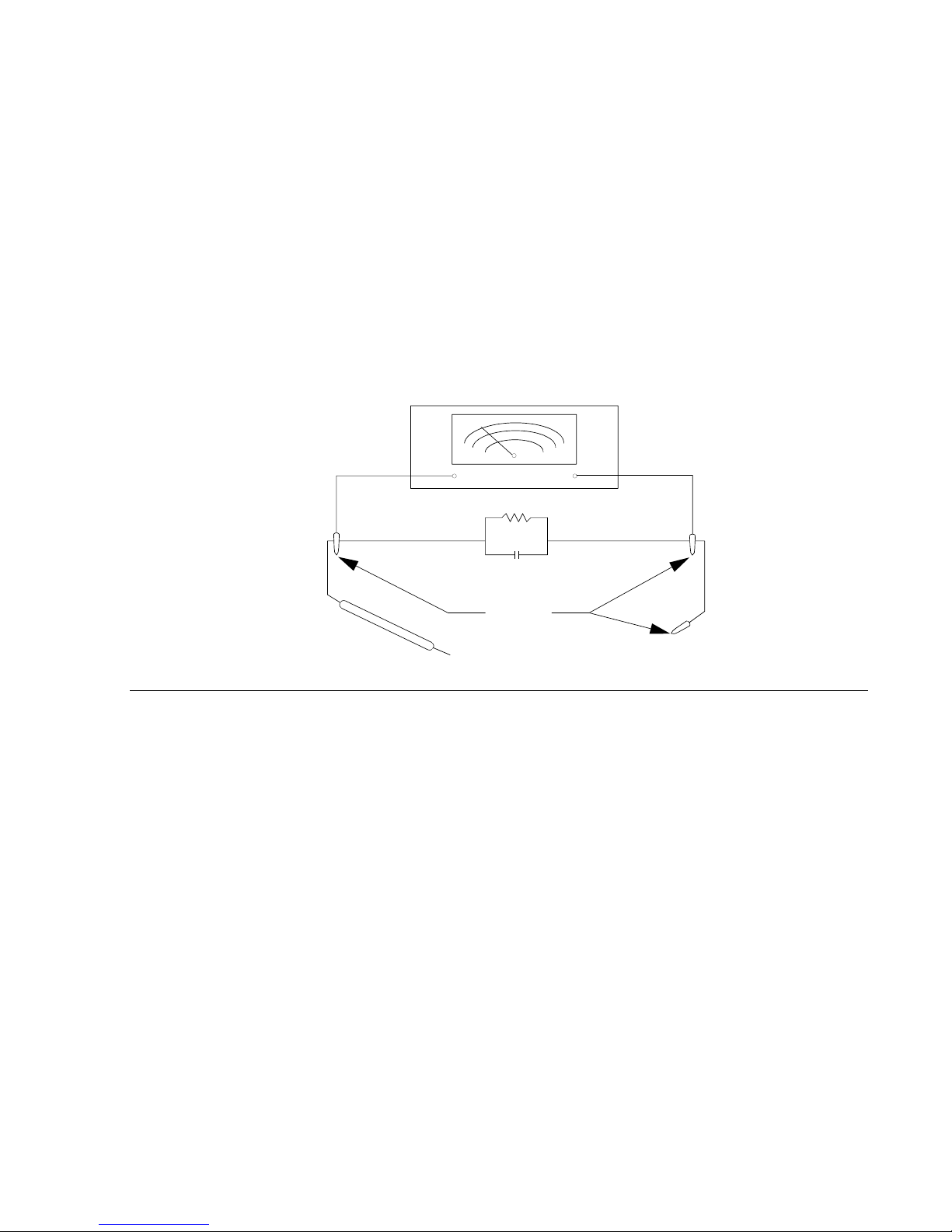
Plug the AC line cord directly into a line voltage AC receptacle (do not use an isolation transformer for this test) and turn the
product on. Connect the network (as shown below) in series with all exposed metal parts and a known earth ground such as a
water pipe or conduit. Use an AC Voltmeter of 5,000 ohms per volt or higher sensitivity to measure the voltage drop across the
network. Move the network connection to each exposed metal part (metal chassis, screw heads, knobs and control shafts,
escutcheon, etc.) and measure the voltage drop across the network. Reverse the line plug and repeat the measurements. Any
reading of 4 volts RMS or more is excessive and indicates a potential shock hazard which must be corrected before returning
the product to the user .
SAFETY NOTIC E
CAUTIO N
Danger of explosion if battery is incorrectly replaced. Replace only with the same or equivalent type recommended by the
equipment manufacturer. Discard used batterie s according to manufacturer's instructions.
Advarsell
Lithiumbatteri. Eksplosionsfare ved fejlagtig håndering.
Udskiftning må kun ske med batteri as samme fabriket og type.
Lebér det brugte batteri tilbage til leverandoren.
Norge: ADVARSEL
Lithiumbatteri - Eksplosjonsfare.
Ved utskif tning benyttes kun batteri som anbefalt av appa ratfabrikanten.
Brukt batteri returneres apparatleverandoren.
Sverige:
VARNING
Explosionsfara vid felaktigt batteribyte.
Använd samma batterityp eller et ekvivalent typ som
rekommenderes av apparattillverkaren,
Kassera använt batteri enlig fabrikantens instruktion.
Finland:
VAROITUS
Paristo voi räjähtää, jos se on virheeliseeti ansennettu
Vaihda p aristo ainoastaan laitevalmistajan suosittelemaan
tyyppoonn, Hävitä käytetty paristo valmistajan ohjeiden mukaisesti.
VOM
AC SCAL E
10K
2W
0.01MF
CERA MIC RF
BYPASS CAP
TEST CLIPS
CONNECTE D TO K NO WN
EARTH GROUND
TEST
PROBE
TO EXPOSED METAL PARTS

#3300P
#3300WP
-Table of Contents-
1
2
3-1,3- 2
4
5
6-1,6- 2
7
8-1
8-2
8-3
9-1~9-3
10-1~10-7
1.SPECIFICATIONS
2.B LOCK DIAGRAM
3.DISASSEMBLY PROCEDURE
4.TEST AND ADJUSTMENT
5.WIRI NG CONNECTION
6.WIRING CHART
7.PRI NTED WIRI NG BOARD ASS'Y LIS T
8.SCHEMATICS
PWH-74C
PAH-74B
CTH-37A
9.TECHNICAL DESCRIPTI ON
10.PARTS LIST
-1-
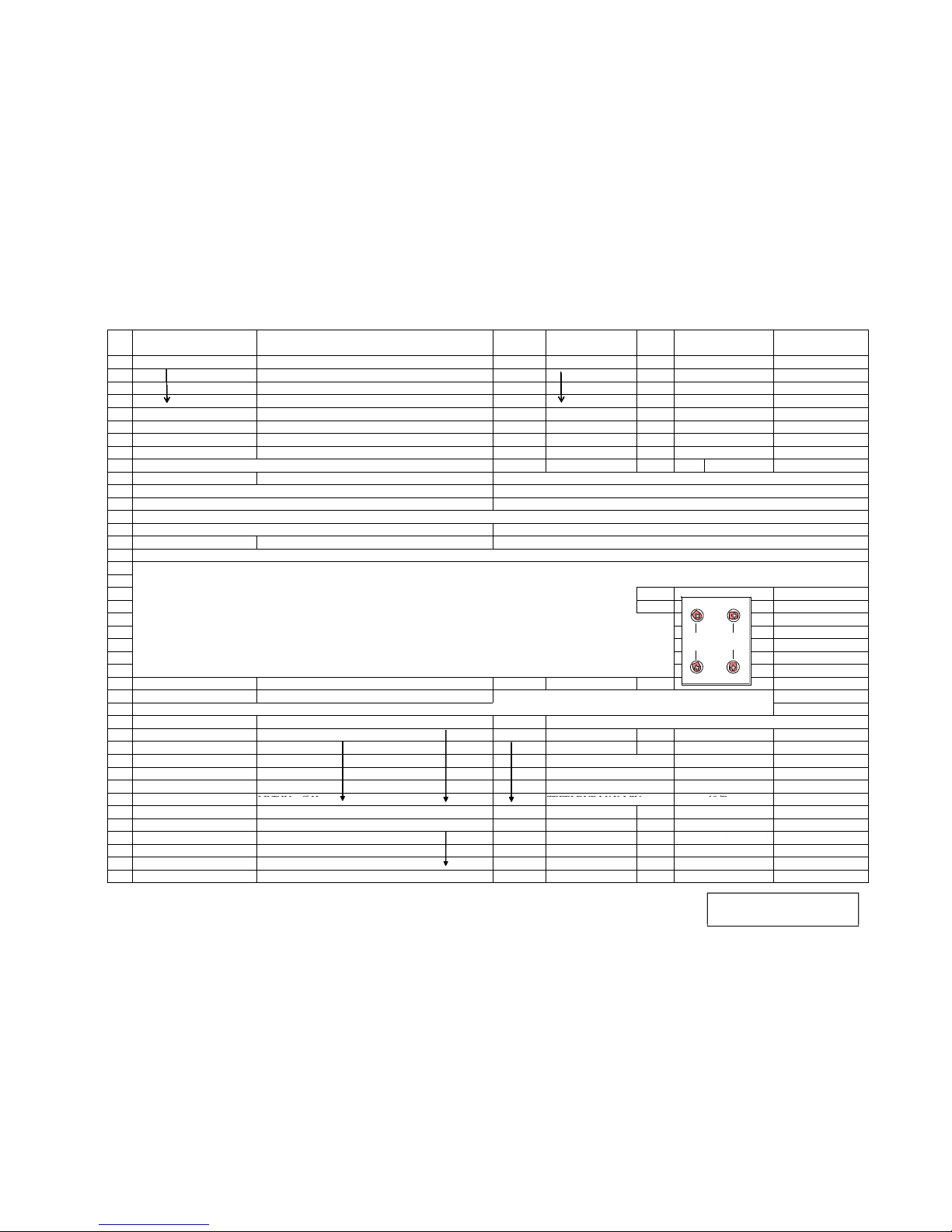
1.SPECIFICATIONS
TYP E
POWER OUTPUT
SPEAKER
OVERDRIVE
CONTROL
MOTOR
ROTORADJUST
LED
TERMINAL
POWER CONSUMP T ION
DIMENSION
WEIGHT
OPTIONAL
:1-Channel(Rotary Channel Only) REAL 2-Rotor
:HORN Rotor 80 W,DRUM Roto r 22 0 W
(TOTAL POWER 300W)
:ROTARY H ORN DRIVER H e a v y -Duty 100 W,
WOOFER 38cm Massive15"(38cm)
:VACUUM TUBE 12AX7X1
TUBE DRIVE LEVEL, TU BE ON /OFF,TUBE MODE
:EQ BASS, MIDDLE,TREBLE
VOLUME,H ORN LEVEL, SUB WOOFER VOLUME
:BRUSH L ESS DC MOTORx2
:HORN RI SE TIME,FA L L TIME, SLOW SPEED, FA ST SPEED
DRUM RISE TI ME, FALL TIME, SLOW SPEED,FAST SPEED
:FAST,SLOW,STOP
:LESLIE 11PIN SOCKET with STATIONARY L,R THROUGH OUTPUT,
LESLIE 8PI N,LINE INPUT,L INE OUT/ SU B WOOFER OU T
FOOT SWITCH (SLOW/FAST/STOP) AC INPUT
:AC 100V,120V,220~240V,230~240V, 210W
:63(W)x52(D)x90(H)cm
:57kg
:LESLIE CABLE 11 PIN(LC11-7M)
LESLIE CABLE 8PIN(LC8-7M )
FOOT SWITCH FS-9H
1) Horn Driver
2) Power Board
3) Preamp. Board
4) SP Spacer ass'y
5) WR-HZ144-A
6) Upper motor & Bearing ass'y : Pan head machine screw M4x20 fixing the driver mount --> Changed to M4x16
Changes from Leslie 3300
*
: Changed to PA-D50Z made by P.AUDIO
: PWH-72A --> Changed to PWH-74C
: PAH-74A --> Changed to PAH-74B
: Changed to SP Sp acer P
: Sleeve added to the terminal for the driver
DC SER VO
MOTOR 1
ROTARY
HORN
HORN
DRIVER
SPEAKER
15"WOOFER
DC SER VO
MOTOR 2
DRUM
ROTOR
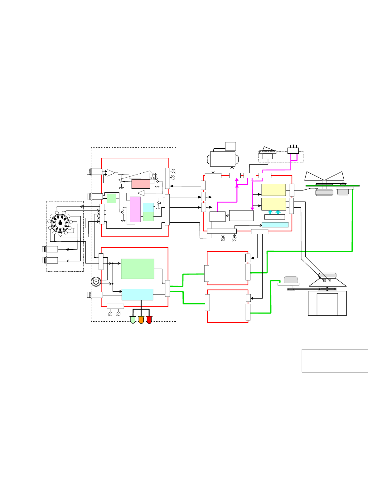
2.BLOC K DIAGRAM
#3300P, #3300W P
#3300P
#3300WP
POWER SUPPLY
& POWER A MP
TUBE PREAMP
PWH-74C
PAH-74B
CTH -37A
LGH-43A
LGH-43A
CONTROL PANEL
Power SW PANEL
Powe r SW
PANEL
MOTOR SPEED
CONTROLLER
MOTOR
DRIVER 1
MOTOR
DRIVER 2
LINE IN
SUB WOOFER
/ LINE OUT
Stationary-L OUT
Stationary-R OUT
POWER
TRANS
EPH-123
SLOW /FAST/S TOP
FOOT SW
REMOTE
POWER ON
RELAY
1 - Rotary sig. IN
2 - Stationary-L IN
3 - Stationary-R IN
4 - Audio GND
5 - Control GND
6 - Power ON
7 - LE S.FAST
8 - LE S.SLOW
11- +15V OUT
Rotar y SIG
SLOW / F AST
S/F
8PIN ROT SIG
+24V
P.S.
+24V
P.S.
+15V
+15V
-15V
80W HORN
POWER AMP
220W BTL
POWER A MP
+37V TUBE P.S .
HORN SIG
BASS SIG
+15V
-15V
+15V
-15V
EPH-122 SUB TRANS
for POWER RELAY
AC INLET
POWER
SWITCH
J110
J106
J107
J109
J108
J112
C
N
3
CN2
CN1
CN1
CN2
CN3
LESLIE 11PIN
LESLIE 8PIN
FAST SLOW STOP
SPEED I ND. LED
1
11
10
9
8
7
6
5
4
3
2
POWER O N
J303
J302
J101
J111
J103
J102
J301
Voltage
Select
Plug
Primary
IC1A
MIX AMP
IC1B
Tube Drive
Level
VOLUME
Tube MODE
SUB
WOOFER
VOLUME
HORN
LEVEL
JK3
JK4
JK2
JK1
Tube 12AX7
HPF
LPF
LPF
BASS
MID
TREBLE
3BAND
EQ
IC3B
U1
U6,Q5 Thermo Sensor
U2
IC2
LED1
LED2
LED3
IC3C
IC3A,D
U2 HORN/DRUM
Speed, Rise & Fall
Time Control
U1 CPU
Motor Control
J201
J205
Cooling Fan
J202
J104
#3300P
#3300WP
#3300P, #3300W P
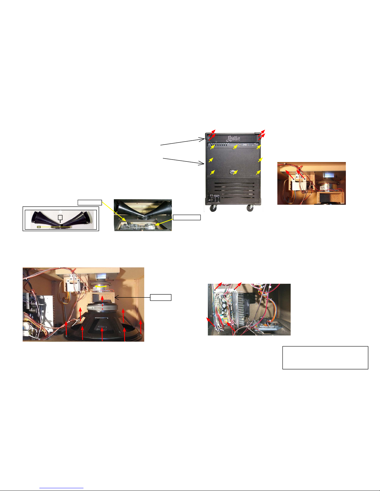
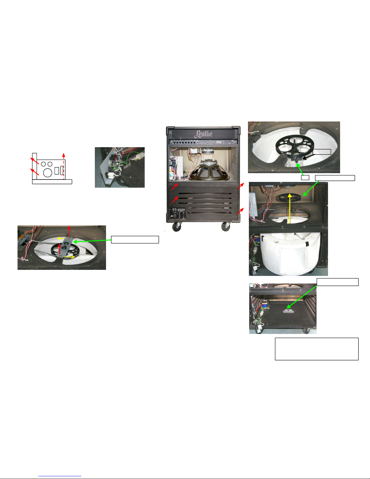
3.DISASSEMBLY PROCEDURE
3. DISASSEMBLY PROCEDURE
#3300P, #3300W P
1/2
2.Remove the Middle Rear Panel.
Remove the 8 tapping screws(type-1 truss,Ø4x30),then remove the Middle Rear Panel.
1.Remove the Upper Rear Cover.
Remove the 4 tapping screws(type-1 truss, Ø4x16),then remove the U pper Rear Cover.
NOTE: Unplug the Power Cable from the u nit before disassembling it.
3. Procedure to change the Horn Rotor Belt..
Locate a sm all Philips screwdriver (of maximum total length 8.5cm).Drop the Belt by tilting in
the Motor. Next r emove the 2 small screws (bind M3x16 for fixing the Horn R otor) and remove
the Horn from the Bearing.
Place the new Belt around the Bearing Ass'y and after mounting the Horn Rotor,
lift it onto the Motor Pulley and the Horn.
Fig. 3
Motor Pull ey
Bearing Ass'y
6. Remove the Motor Drive PWB.
Remove the Cover Bracket of the Motor Cover Ass'y by removing the 2 tapping scr ews (type-1 bind,
Ø3x10).
Slide and remove the PWB with the Connector from the Cover.
Keep track of the wiring for the UP Motor and the Low Motor.
(They are Similar in appearance but not interchangeable.)
Fig. 7
4. Procedure to replace the Horn Driver:
Pull out the "SP Spacer" (between the Horn D river and the Woofer Speaker).
Remove the con necting leads from the horn driver.
Rotate the Driver Unit to the left and remove it from the Upper Horn Motor Ass'y.
Be careful not to pinch your finger s between the Woofer Magnet and the Horn Driver.
(as the ma gnetic pull from the woofer magnet is strong.)
5. Removing th e 15" Woofer Spea ker.
Remove the 8 scr ews W Sems (P=3 M4x30).
Place a thick piece of cardboa rd etc. between the Magnets of the Speaker a nd the
Horn Driver and avoid both Magnets from sticking together.
7. Remove the PWH -74C.
First remove the wiring(s) from the PWB.
Next rem ove the 4 tapping screws (type-1 truss, Ø4x16);
(2 are horiz ontal on the top, 1 is on the bottom,
and another fixes the heat-sink bracket).
Fig. 6
Fig. 1,2
Fig. 4,5
SP Spa cer
#3300P
#3300WP
#3300P, #3300W P
3. DISASSEMBLY PROCEDURE
2/2
Fig. 12-E
Fig 12-D,E
Fig. 12-C
Link Drive
Pin.
9. Remove the Bottom Rear panel.
Pull the panel up from the unit after removing the 4 tapping screws (type-1 truss,
Ø4x30). Slide it down when remounting.
Fig 10-1
Fig 10-2
10. Removing the Power Switch Panel.
Remove the 3 tapping screws (type-1 truss, Ø4x16) (2 horiz ontal,
1 vertical).
If necessary, r emove the 2 GND wirings inserted to the Faston termina l.
Turn the U P Bearing Ass' y.
11. How to change the wide Drum Rotor Belt.
First remove the Belt by tilting in the Lower Motor. After removing the
2 screws W Sems (P=3, M4x30), turn and detach the UP Bearing Ass'y
from the Ca binet.
Take out the Belt from the opening of this Cabinet, and replace it with a
new one.
12. Remove the Drum Rotor.
NOTE: Don't let an unexperienced service staff remove the Drum Rotor.
It requires a certain level of technique to put the shaft into the
Lower Bea ring Ass'y at th e assembly.
A, Remove the 15" Spea ker and the Power Switch Panel.
B, Pull out the UP Bear ing Ass'y from th e Pulley Ass'y.
C, Pull out th e rubber Link Drive (for conducting the rotation of the pulley
to the rotor) from the Rotor Pin,
D, Slowly take it out from the Drum Rotor by turning
the Pulley and the Shaft.
E, When the Shaft is pu lled out from the Lower Bea ring Ass'y, move the Drum Rotor
to the front.
F, Then slide it from underneath the Horn Driver, and take out the Shaft from the
Rotor. Finally, take out the Drum Rotor from the Cabinet.
Fig 11
Shaft and Pulley Ass'y
LOW ER Bea ring ASS'Y
Fig. 9
#3300P
ADJUSTM
RISE
TIME
FALL
TIME
HORN
DRUM
1. a
DC Power Supply Check +15V PWH-74C J110-6
b
-15V J110-1
DC +15V ±5%
DC -15V ±5%
STEP
NOTESUBJECT TEST POINT
ENT
POINT
SPECIFICATIONSETTING INPUT
b
15V
J110 1
c
+37V MAIN VOLUME 0: J111-4
d
+24V J112-3,4
DC 15V
±5%
DC +40V ±4V
DC +24V ±1V
e
LESLIE 11PIN DC OUT Check LES11P -PIN11,(GND)
f
Remote Power ON Check Power SW OFF Short PIN6 -PIN 4
DC +15V ±5%
Power ON
RISE
TIME
FALL
TIME
HORN
DRUM
2.
Resetting Rotation Speed to Factory Settings
Switch ON the power, pressing the Foot SW, and wait for 5 sec. Check the STOP LED (RED) slowly flashes and the HORN and the DRUM ROTOR turns at SLOW.
RISE
TIME
FALL
TIME
HORN
DRUM
a
SLOW SPEED Adjustment: Adjust SLOW by the TRIMMER on the panel
.
Turn the HORN side, so the FAST (GRN) LED turns on
. As
the rotation approaches the standard, it flashes
.
Turn the DRUM side, so the SLOW (ORG) LED turns on. (40±3rpm*)
Press on the Foot SW and switch the Motor to FAST, and wait until the Brake LED (RED) turns on.
RISE
TIME
FALL
TIME
HORN
DRUM
b
FAST SPEED Adjustment: Adjust FAST by the TRIMMER on the panel
.
Turn the DRUM side, so the SLOW (ORG) LED turns on. (400±10rpm*)
Turn the HORN side, so the FAST (GRN) LED turns on
. As
the rotation approaches the standard, it flashes
.
RISE
TIME
FALL
TIME
HORN
DRUM
c
3.
Check the RISE TIME and the FALL TIME of the HORN and the DRUM. (See the figure on the right)
'
After checking, switch OFF the power and switch it ON again for normal operation.Turn the DRUM side, so the SLOW (ORG) LED turns on
.
RISE
TIME
FALL
TIME
HORN
DRUM
3-1
HORN RISE TIME (SLOW -> FAST)
approx. 2.5 ±0.5 sec. at 10 o'clock pos
iti
on
3-2 HORN FALL TIME (FAST -> SLOW) approx. 2.5 ± 0.5 sec. at 9 o'clock position
3-3 DRUM RISE TIME (SLOW -> FAST) approx. 8 ± 1.5 sec. at 11 o'clock position
RISE
TIME
FALL
TIME
HORN
DRUM
3-4
DRUM FALL TIME (FAST
->
SLOW)
approx. 8 ± 1.5 sec. at the center
If not at these tolerances, adjust by the TRIMMER.
If the TRIMMER must be turned more than 30 degrees from the standard position A malfunction is present.
RISE
TIME
FALL
TIME
HORN
DRUM
4
CHECK Power AMP .
Set TUBE MODE, BASS, MID, TREBLE, HORN LEVEL at the center.
TUBE DRIVE LEVEL is TUBE OFF; SUB WOOFER VOL is MAX
RISE
TIME
FALL
TIME
HORN
DRUM
a
TUBE ON
/
OFF CHEC
K
MAIN VOLUME: Grade 2 Adjust the VR9 of the PAH74B so as to not change the output at the TUBE ON/OFF
b
WOOFER SP LINE IN 800Hz 80mV LINE IN PWH-74C J104-2,4 (LINE OUT 15mVrms)
c
HORN SP LINE IN 8kHz PWH-74C J102-1
600mV rms ±30mV
550mV rms ±6mV
RISE
TIME
FALL
TIME
HORN
DRUM
c
SUB WOOFER OUT LINE IN 80Hz
d
TONE VR Check LINE IN 80Hz BASS VR MAX-MIN
e
LINE IN 2kHz MID VR MAX-MIN
+4dB,-17dB
+4.5dB,-6.5dB
SUBWOOFER OUT JAC
K
130mV rms ±12m
V
RISE
TIME
FALL
TIME
HORN
DRUM
f
LINE IN 8kHz TREBLE VR MAX-MIN
5.
CHECK the Noise MAIN VOLUME: MAX
±10dB
RISE
TIME
FALL
TIME
HORN
DRUM
a
Woofer SP- Noise Level PWH-74C J104-2
b
Woofer SP+ Noise Level PWH-74C J104-4
c
HORN SP Noise Level PWH-74C J102-1
1.0mV max (IEC"A"net)
1.0mV max (IEC"A"net)
1.5mV max (IEC"A"net)
RISE
TIME
FALL
TIME
HORN
DRUM
#3300P, #3300WP
RISE
TIME
FALL
TIME
HORN
DRUM
4.TEST AND ADJUSTMENT
RISE
TIME
FALL
TIME
HORN
DRUM
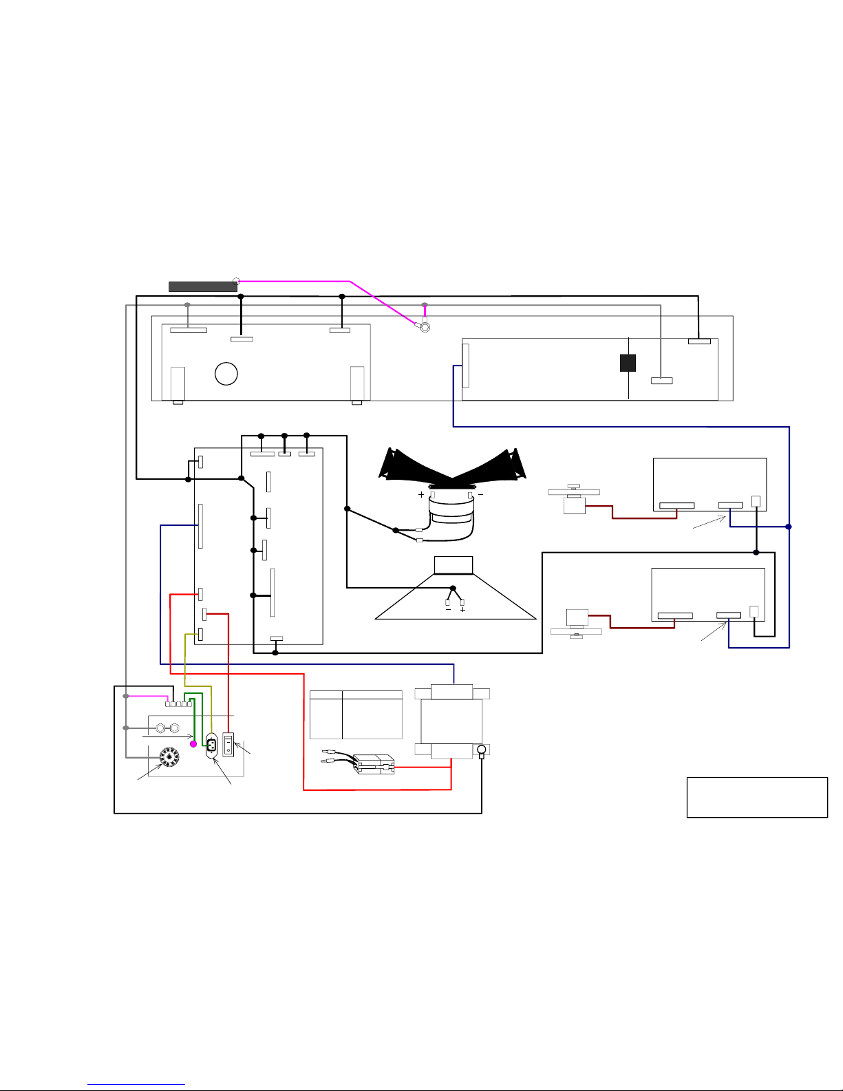
5.WIRING CONNECTION
#3300P, #3300W P
#3300P
#3300WP
POWER
SWITCH
AC INLET
GND TERMINAL
PANEL
Earth
11PIN
100V
120V
220V
240V
00106-00241
00106-00242
00106-00243
00106-00244
Par t No.
Volts
Voltage Select Plug
Secondary
Primar y
POWER SW PANEL
BLK
Horn Driver
Woofer
CONTROL PANEL
WR-HZ144-D
WR-HZ144-A
WR-HZ144-A
WR-HZ144-E
WR-HZ144-D
REAR COVER
WR-HZ144-G 2/2
WR-HZ144-B
WR-HZ144-D
WR-HZ144-A
MOTOR CABLE
MOTOR CABLE
PANEL GND
J301
5P
6P
7P
PAH-74B
Tube PreAmp
J302
J303
EPH-123
PWH-74C
Power
J106
J107
J108
J109
J112
J110
J113
J103
3P
4P
2P
8P
5P
5P
10P
4P
J111
3P
J101J102
J105
J104
4P
4P
2P
3P
UPPER MOTOR ASSY
LOWER MOTOR ASSY
J205
8P
J204
J203
J202
5P
J201
6P
CTH-37A
Motor Control
LGH-43A 1
Motor Driver
CN2
CN1
CN3
9P 10P
2P
LGH-43A 2
Motor Driver
CN2
CN1
CN3
9P 10P
2P
WR-HZ144-G 1/2
RED
White
Red
POWER
TRANS
Red
5PIN
R Red
L White
Pink
5PIN
Pink
Black
Red
Black
CN3
CA UTION !!
CN3
CA UTION !!
WR-HZ144-C
 Loading...