

Hammond LESLIE 2102, LESLIE 2101 Service Manual
SERVICE MANUAL
SUZUKI MUSICAL INST.MFG.CO.,LTD.
25-12,RYOKE 2-CHOME,HAMAMATSU, JAPAN
~HA<O>
Dec.2002
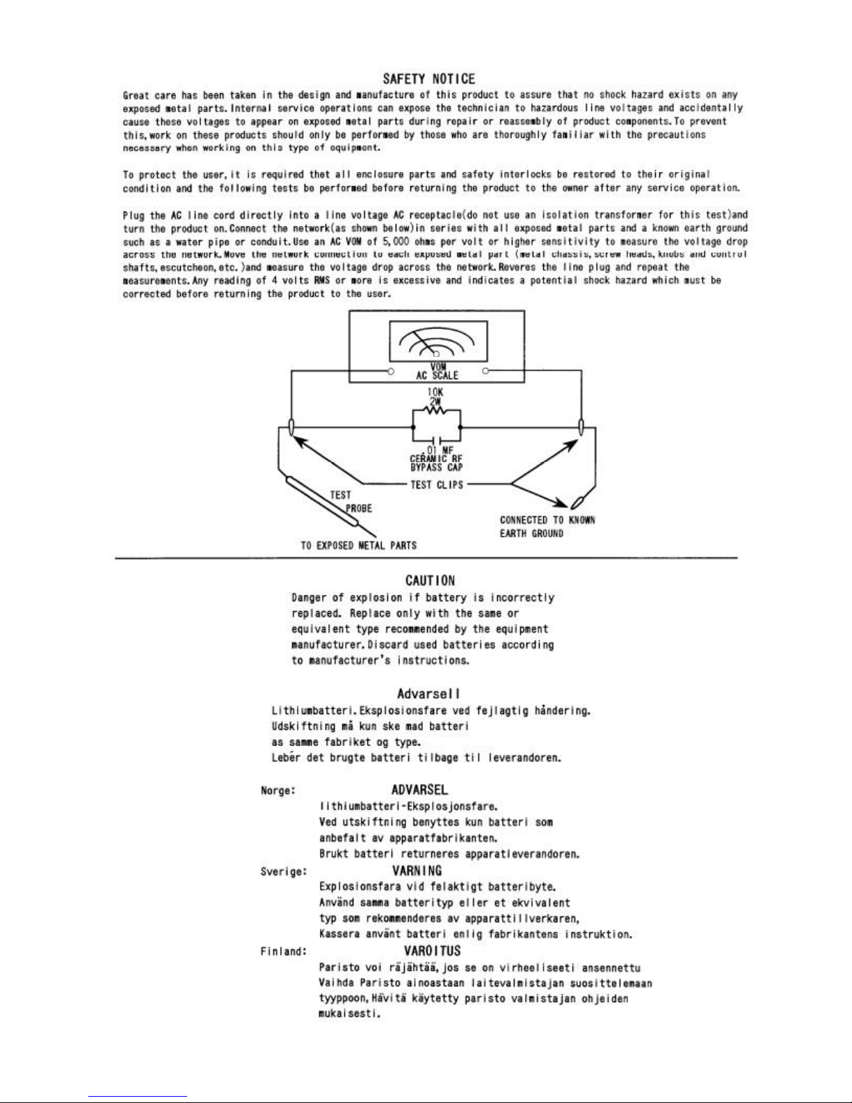
CAUTION !
see safety notice inside
LESLIE 2102
(SILVER)
LESLIE 2101
(BLACK)
Rotary Unit
Units shown with optional stands.
#2101/ #2102
-Table of Contents-
1
2
3-1,3-2
4
5
6-1,6-2
7
8-1
8-2
8-3~8-5
9
10
11-1~10-3
1.SPECIFICATIONS
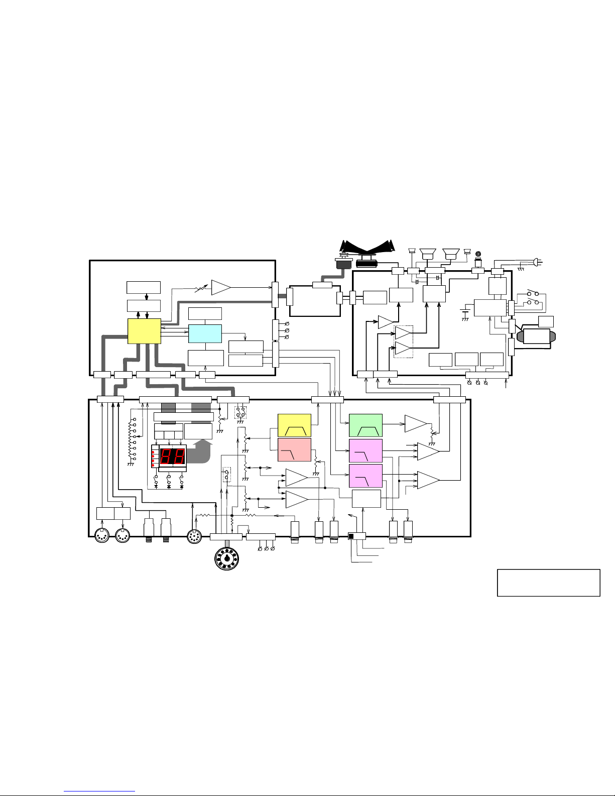
2.BLOCK DIAGRAM
3.DISASSEMBLING PROCEDURE
4.TEST AND ADJUSTMENT
5.WIRING CONNECTION
6.WIRING CHART
7.PRINTED WIRING BOARD ASS'Y LIST
8.SCHEMATICS
PWH-68A
SWH-492A
EFH-237A 1/3~3/3
9.WARNING
10.TECHNICAL DESCRIPTION
11.PARTS LIST
-1-
1.SPECIFICATIONS
TYPE
POWER OUTPUT
SPEAKER
CONTROL
DISPLAY
TERMINAL
POWER CONSUMPTION
DIMENSION
WEIGHT
OPTIONAL
Rotary Unit #2101 (Black) , #2102 (Silver)
: 3-channel (ROTARY, STATIONARY-L , STATIONARY-R)
HORN ROTOR(ACOUSTIC)
LOWER ROTOR(2channel DSP)
: ROTARY HORN 50W, LOWER CH 50WX2
: ROTARY HORN COMPRESSION DRIVERX1,
13cm WOOFERX2.5cm TWEETERX2
: VOLUME:
STA-L , STA-R , ROTARY , OVERDRIVE
8-POSITION FUNCTION SWITCH, VALUE UP/DOWN
PRESET 1-2, MEMORY
CHANNEL MODE:
NORMAL-STA MONO, STA ROT BASS-MUTE
: 7segment 2digit LED display
: LESLIE 11PIN SOCKET , LESLIE 8PIN , ROTARY INPUT ,
FOOT SWITCH 1 (PRESET), FOOT SWITCH 2 (SLOW/FAST/STOP)
LINEOUT(STATIONARY-L, STATIONARY-R, ROTARY-L, ROTARY-R)
MIDI IN, MIDI OUT, REMOTE POWER for #2121
: AC 120V,220-230V,230-240V 190W
: 51(W)X52(D)X33(H)cm
: 23kg
: STATIONARY UNIT #2121, LESLIE CABLE 11PIN (LC11-7M)
LESLIE CABLE 8PIN (LC8-7M),LESLIEY CABLE(LC11Y-7M)
STAND ADAPTER(LSA-21) , FOOT SWITCH FS-9H
+5V Reg.
U3
U1A :BPF
125-12kHz
U7 :24bit DAC
U4 : 128K x 8
MTP ROM
U10 : 20bit ADC
PCM1800E
LED
1
2
3
4
LED5(7seg x 2)
LED Driver
U6 & Q4
COM Driver
Q1 Q2 Q3
U11:24bit DAC
U7
PC900V
Q10
A933S
8bit x 3 Matrix
U1B:LPF
125Hz
U2A
MIX AMP
U2B
MIX AMP
U3A :BPF
700-12kHz
U4A:LPF
1.1kHz
STA-L
U5A:LPF
1.1kHz
Low
Rotor
Lch
Horn Rotor ch
Rotary Channel
Low
Rotor
Rch
U3B
AMP
U14A
DC AMP
VR1 GAIN
OFFSET
MOTOR CONTROL DC
U4B
MIX AMP
U5B
MIX AMP
Power Amplifier
& Power Supply
CPU Control & DSP Effect
PreAmp
& Panel Switch
Power On
Mute Relay
Q1,Q2,RL2
13cm Woofer
Lch Rch
Rch
Tweeter
Power Switch
Lch
Tweeter
Rotary Horn
Brushless DC
Servo Motor
FY815-SD3
U2
POWER AMP
STK402-120
POWER AMP
STK404-130
U1
PWH-68A
SWH-492A
EFH-237A
Motor Driver
FYD815SD3-300
to J110-10
R79 thru R85
Leslie Power On
50W50W
50W
50W
Power On
Mute Relay
Q1,Q2,RL1
+5
ROT BASS
MUTE ON/OFF
Q6, Q7
ROT BASS
LEVEL
VR5
VR4
OVER
DRIVE
COM 0
1
8
SW1
MEM
D1
D2 D3
SW2
FUNC.
SEL.
SW3
PRESET
SELECT
COM 1
COM 2
SW5 VALUE
(Rotary Encoder)
ROT IN
VOLUME
VR1
SW4
FUNCTION
SWITCH
Vref
STA-L
VOLUME
VR2
STA-R
VOLUME
VR3
HORN
LEVEL
VR6
J302
J307
J206
J203
J207 J205
J301J305
J306
J103
LESLIE 11PIN
Bass & Stationary
Line out
L/MONO R
LESLIE 8PIN
J101
Rotary
Line out
Rotary
Line IN
1 2
PRESET SLOW/FAST
FOOT SWITCH
LESLIE SLOW / FAST CONTROL
IN OUT
MIDI
L/MONO R
STA-L
STA-R
STA-R
U8 :64KW x 16bit
DRAM
U3 : 1M SRAM
uPD431000AGW
J303
+12
SW6
SLIDE
SWITCH
NORMAL
STA MONO
BASS & STA
MUTE
SW6-2
SW6-2
-12
J304
J102
C28
C29
J104
J105
Voltage
Select
Plug
BT1 3V
Battery
CR2032
+12
Primary
Secondary
-12
+24V Reg.
U6
POWER
TRANS
EPH-115
+5
from J303
AC LINE FI
LTER
L1,C48 to
C52
Remote DC Out
J110 -10
J106
J108
J109
Remote Power
On Relay RL3
Q3,Q4,Q5
J107
J112
CN3
J208
J202 J201
J204
CN1
CN2
U1 :CPU
H8/3007
+12
-12
+5
U9 : DSP
TMS57070
+12V Reg.
U4
-12V Reg.
U5
J111
2.
BLOCK DIAGRAM
#2101/ #2102
#2101/ #2102
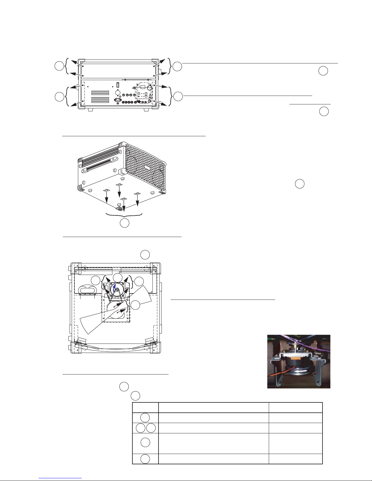
3.DISASSEMBLING PROCEDURE
#2101/ #2102
3-1
B
A
A
B
B
C
D
CAUTION:
<CAUTION>
When reinstalling Motor assembly,make sure that
these screws are tight!
Screw name Part No.
00613-64030
00703-84030
00703-55020
00725-85000
00703-23018
A
a.REMOVAL OF TOP REAR BOARD ASSEMBLY:
Unfasten the four (4) machine screws labeled
in Figure 1 from the rear board.
<FIG.1>
A Tapping,Truss,Ø4x30
Machine screws,W Sems,M4x30
Machine screws,Bind,M5x20
Flange,M5(hexagon nut)
Machine screws,Oval head,M3x18
b.REMOVAL OF BOTTOM REAR PANEL
ASSEMBLY:
Unfasten the four (4) machine screws labeled
in Figure 1 from the rear panel.
<FIG.2>
c.REMOVAL OF ROTARY HORN ASSEMBLY:
Remove the Rear Panel Assembly by following the
procedure outlined in Section b.
Place the Leslie cabinet on it's side which has the
four (4) rubber feet installed on a flat surface.
Unfasten the four (4) machine screws from the
unit as shown in Figure 2.
d.REMOVAL OF MOTOR ASSEMBLY:
1.Remove the Rotary Horn Assembly following the procedure outlined in Section c.
2.Unfasten the four (4) machine screws as shown in Figure 3.
e.REMOVAL OF HORN DRIVER:
Remove the Motor Assembly following the procedure
outlined in Section d.
Disconnect (unplug) the wire assembly from the Driver.
Remove the Horn Driver by rotating the Driver in a
counterclockwise direction.
f.REPLACING THE CLOTH BELT:
1.
2.
3.
C
F
D
E
D
1.
2.
3.
Remove the Rear Panel following the procedure outlined in Section b.
Remove the belt from motor pulley.
Unfasten the four (2) machine screws from the rotary horn after remove the cloth belt as
shown in Figure 3.
E
F
1.
2.
3.
C
<FIG.3>
D
A
F
B
Disconnect the line cord from A.C. Source before disassembling any
portion of this product.

A
B
3-2
#2101/ #2102
A
g.REMOVAL OF SPEAKER GRILLE:
h.SPEAKER REMOVAL:
1.Place the Leslie Cabinet on a flat surface with the top of the Leslie facing up.
2. Unfasten the two (2) screws labeled in Figure 4.
3.Remove the Top Rear Board Assembly by following the procedure outlined in Section a.
4.Remove the speaker grille by gently pushing the grille out from the inside of the cabinet.
1.Remove the Speaker Grille by following the procedure outlined in Section g.
2. To remove the 5cm speaker , unfasten the two (2) screws labeled in Figure 5.
3.To remove the 13cm speaker , unfasten the four (4) screws labeled in Figure 5.
PUSH
A
A
B
C
Screw name Part No.
00613-53025
00613-64012
00613-64016
A Tapping,Bind,Ø3x30,ZnB
A Tapping,Truss,Ø4x12
A Tapping,Truss,Ø4x16
A
B
C
<FIG.4>
<FIG.5>
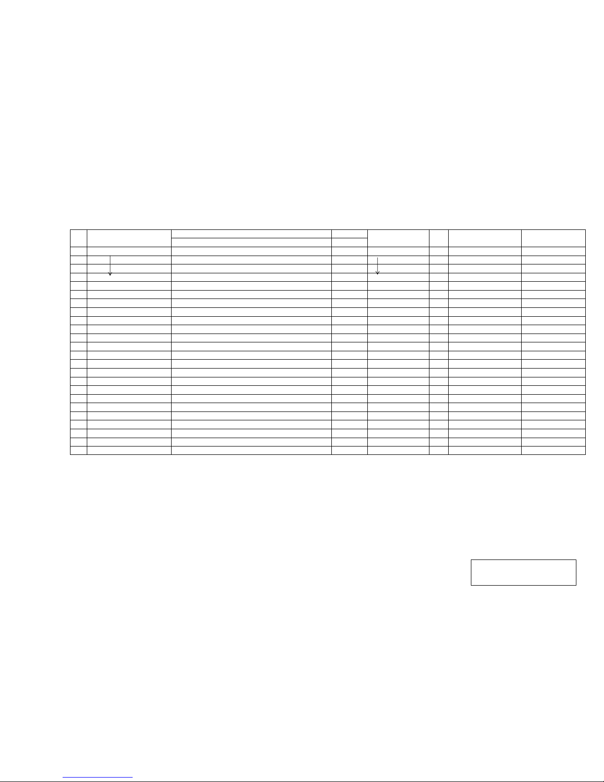
#2101/ #2102
OVERDRIVE VOL : Min.
SETTING INPUT
1. a
DC Poewr Supply +5V PWH-68A J110-7
b
+12V J110-5
c
-12V J110-1
d
+24V J112-3
e
Remote DC OUT Remote DC JACK-Core
f
Remote DC OUT Connect to Leslie 2121 thru DCC-2 cable Remote DC JACK-Core
g
LESLIE 11PIN 11 DC OUT LES11P -PIN11
2. a
Motor Speed Control Voltage LESLIE FAST , Function sw Fast Speed Value : 9 (Preset 1) EFH-237A J208-5 VR-1
* round per mintue of Horn
b
LESLIE SLOW , Function sw Slow Speed Value : 5 (Preset 1) EFH-237A J208-5
3. a
Stationary Lch SP Level STA-L VOL Max 400Hz SINE WAVE 1Vrms LES11PIN-2 PWH-68A J104-2
b
Stationary Rch SP Level STA-R VOL Max 400Hz SINE WAVE 1Vrms LES11PIN-3 PWH-68A J104-4
c
Rotary HORN SP Level ROTARY VOL Max , HORN LEV Max , 1kHz SINE 1Vrms LES11PIN-1 PWH-68A J102-1 Leslie Fast Mode
4. a
Stationary Lch Line out Level STA-L VOL Max 400Hz SINE WAVE 1Vrms LES11PIN-2 STA-L OUT JACK
b
Stationary Rch Line out Level STA-R VOL Max 400Hz SINE WAVE 1Vrms LES11PIN-3 STA-R OUT JACK
c
Rotary Line out Lch Level ROTARY VOL Max , ROT BASS LEV Center, 1kHz 1Vrms LES11PIN-1 ROT OUT-L JACK Leslie Fast Mode
d
Rotary Line out Rch Level ROTARY VOL Max , ROT BASS LEV Center, 1kHz 1Vrms LES11PIN-1 ROT OUT-R JACK Leslie Fast Mode
5. a
Stationary Lch SP Noise Level STA-L,-R,ROTARY VOL Max PWH-68A J104-2
b
Stationary Rch SP Noise Level STA-L,-R,ROTARY VOL Max PWH-68A J104-4
c
Rotary HORN SP Noise Level STA-L,-R,ROTARY VOL Max PWH-68A J102-1
#2101/ #2102
1.0mV max (IEC"A"net)
1.0mV max (IEC"A"net)
19V rms ±2V
19V rms ±2V
15V rms ±1.5V
3.1V rms ±0.4V
4.
3.1V rms ±0.4V
300mV rms ±40mV
350mV rms ±40mV
1.0mV max (IEC"A"net)
TEST AND ADJUSTMENT
DC +12V ±5%
6.60V (400±7rpm)*
0.57±0.05V (36±1rpm)*
DC -12V ±5%
DC +24V ±1V
DC -18V ±1.5V(open)
DC -3.0V ±0.4V(on Load)
DC +5V ±5%
DC +12V ±5%
STEP NOTESUBJECT TEST POINT
ADJUST
MENT
POINT
SPECIFICATION
 Loading...