

Page 1
*#1
Model:
ank You and congratulations on your choice of a genuine HAMMOND
Organ.
e A-405SP is a Spinet Organ featuring the traditional Drawbar sounds
of a vintage Hammond Organ, Realistic Extra Voices, and a convenient
MIDI sequencer onboard.
Please read this manual thoroughly before using your A-405SP and refer
to it as necessary.
#52
Owner’s Manual
Page 2
2
IMPORTANT SAFETY INSTRUCTIONS
Read these instructions.
Keep these instructions.
Heed all warnings.
Follow all instructions.
Do not use this apparatus near water.
Clean only with dry cloth.
Do not block any ventilation openings.
Install in accordance with the manufacturer’s instructions.
Do not install near any heat sources such as radiators, heat registers,
stoves or other apparatus (including ampli ers) that produce heat.
Do not defeat the safety purpose of the polarized or grounding-type
plug. A polarized plug has two blades with one wider than the other.
A grounding type plug has two blades and a third grounding prong.
The wider blade or third prong is provided for your safety. If the provided plug does not t into your outlet, consult an electrician for replacement of the obsolete outlet.
Protect the power cord from being walked on or pinched, particularly at plugs, convenience receptacles, and the point where they exit
from the apparatus.
Only use attachments/accessories speci ed by the manufacturer.
Use only with the cart, stand, tripod, bracket,
or table speci ed by the manufacturer, or sold
with the apparatus. When cart is used: use caution when moving the cart/apparatus combination to avoid injury from tip-over.
Unplug this apparatus during lightning storms,
or when unused for long periods of time.
Refer all servicing to quali ed service personnel. Servicing is required
when the apparatus has been damaged in any way, such as powersupply cord or plug is damaged, liquid has been spilled or objects
have fallen into the apparatus, the apparatus has been exposed to
rain or moisture, does not operate normally, or has been dropped.
Apparatus shall not be exposed to dripping or splashing and no objects lled with liquids, such as vases, shall be placed on the apparatus.
WARNING: To reduce the risk of re or electric shock, do not expose
this apparatus to rain or moisture.
*#1 #52
The lightning ash with arrowhead symbol within an equilateral triangle, indicates that dangerous voltage constituting a risk of electric
shock is present within this unit.
The exclamation point within equilateral triangle, indicates that there
are important operating and maintenance instructions in the literature accompanying this unit.
In case in the future your instrument gets too old to play/use or
malfunctions beyond repair, please observe the instructions of
this mark, or, if any question, be sure to contact your dealer or
your nearest town or municipal o ce for its proper disposal.
Owner’s Manual
Page 3
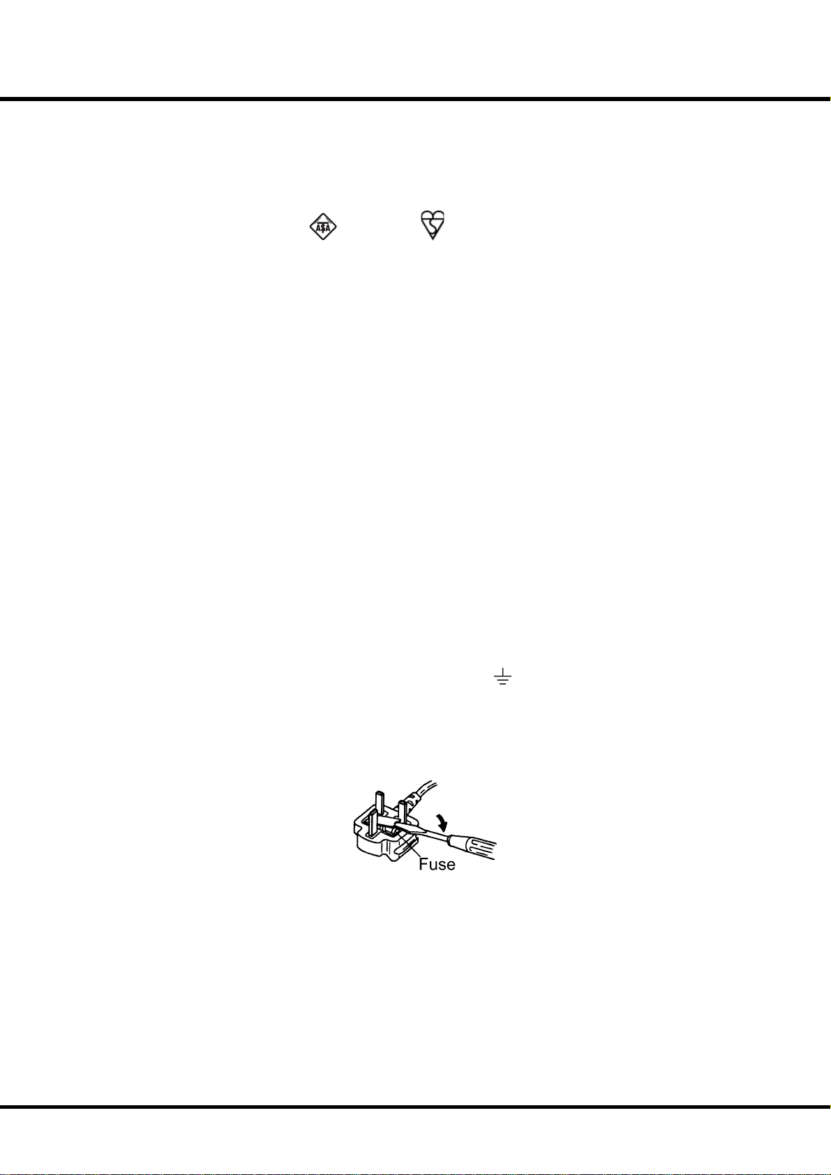
FOR UNITED KINGDOM:
FOR YOUR SAFETY, PLEASE READ THE FOLLOWING TEXT CAREFULLY
This appliance is supplied with a molded 3-pin mains plug for your safety and convenience.
The plug contains a 5 amp fuse.
Should the fuse need to be replaced, please ensure that the replacement fuse has a rating of 5
amps and that it is approved by ASTA or BSI to BSI1362.
3
Check for the ASTA mark
If the plug contains a removable fuse cover, you must ensure that it is re tted when the fuse is
replaced.
If the fuse cover is lost, the plug must not be used until a replacement cover is obtained.
A replacement fuse cover can be obtained from your local Hammond Dealer.
IF THE FITTED MOULDED PLUG IS UNSUITABLE FOR THE SOCKET OUTLET IN YOUR HOME, THEN
THE FUSE SHOULD BE REMOVED AND THE PLUG CUT OFF AND DISPOSED OF SAFELY.
THERE IS A DANGER OF SEVERE ELECTRICAL SHOCK IF THE CUT-OFF PLUG IS INSERTED INTO ANY
13 AMP SOCKET.
If a new plug is to be attached to the cord, please observe the wiring code as shown below.
If in any doubt, please consult a quali ed electrician.
IMPORTANT - The wires in this mains lead are coloured in accordance with the following code:
Blue: Neutral
Brown: Live
As the colours of the wires in the mains lead of this unit may not correspond with the coloured
marking identifying the terminals in your plug, proceed as follows.
The wire which is coloured BLUE must be connected to the terminal in the plug which is marked
with the letter N or coloured BLACK.
The wire which is coloured BROWN must be connected to the terminal in the plug which is
marked with the letter L or coloured RED.
or the BSI mark on the body of the fuse.
Under no circumstances should either of these wires be connected to the earth terminal of the
three-pin plug, marked with the letter E or the Earth Symbol
To replace the fuse, open the fuse compartment with a screwdriver and replace the fuse and
fuse cover.
.
Introduction
Page 4

4
IMPORTANT - PLEASE READ
Your Hammond Organ A-405SP is designed to give you the true and authentic sound of Hammond
Harmonic Drawbars, as well as provide you a large variety of features to allow great fl exibility in how
you want to use the keyboard. is Owner’s Manual is designed to explain the operating features of
your Hammond A-405SP as simply and graphically as possible.
Because we want to make this manual, as well as the keyboard itself, as easy to understand as possible,
the explanations in this manual are grouped by subject matter, and not in the order in which they
necessarily appear in the display (the screen in the Great left end block). For example, all functions
pertaining to Drawbars are grouped together, all Percussion features are treated as a group, and so on.
Also, each feature is treated as an explanation unto itself, and does not require you to already have
prior working knowledge of some other feature. e explanations are presented such that, if you follow the steps, will be identical to that shown in the manual at that stage of the explanation.
Do not be daunted by the number of steps required to perform each operation. Each step is simple.
Simply bear these things in mind:
1. Read each step carefully.
2. Don’t skip any of the steps.
3. Don’t perform the steps out of sequence.
With these guidelines, you are well on your way to mastering all of the many sounds and features of
your Hammond A-405SP.
*#1 #52
Owner’s Manual
Page 5
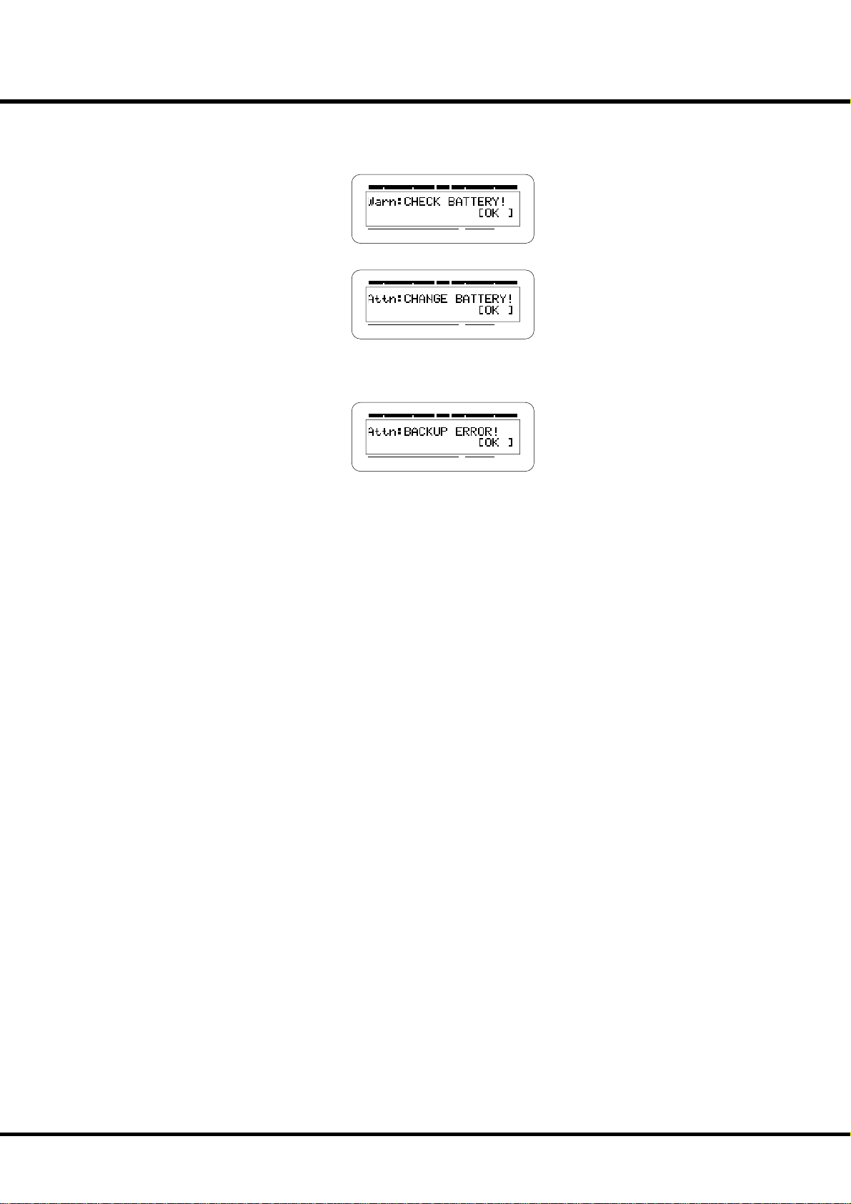
BATTERY BACK UP
Your A-405SP uses a battery-backed RAM to remember your changes to the Parameters.
When the battery voltage becomes low, the Display will show:
SWELL PEDAL GREAT
TRANSPOSEPRESET
SWELL PEDAL GREAT
TRANSPOSEPRESET
If you see these messages, you should immediately back up your parameter changes, if you
have made any. If there is no battery installed in the unit, or if the battery is completely
dead, the Display will show:
SWELL PEDAL GREAT
TRANSPOSEPRESET
5
After the above message is displayed, the A-405SP will re-initialize itself, and the factory
default settings will be restored (except Combination Presets, Leslie Cabinets and Custom
Tone-Wheels). erefore, it is a good idea to periodically save your data to CompactFlash™
card.
CAUTION: In order to change batteries, be sure to ask your dealer or store.
Introduction
Page 6

6
Table Of Contents
IMPORTANT SAFETY INSTRUCTIONS ................................................ 2
IMPORTANT - PLEASE READ ................................................................. 4
BATTERY BACK UP ................................................................................... 5
MAIN FEATURES .......................................................................................9
HOW TO ASSEMBLE ..............................................................................10
Components ..................................................................................................10
Connect the Pedalboard ...........................................................................11
Bench ...............................................................................................................11
Manual Lid ......................................................................................................11
Put on the Music Rack ................................................................................11
NAMES AND FUNCTIONS ...................................................................12
Top Panel ........................................................................................................12
End Block ........................................................................................................14
Manual Bottom .............................................................................................15
Rear Panel .......................................................................................................15
Pedals ...............................................................................................................16
HOOK-UP ......................................................17
BASIC HOOK-UP ..................................................................................... 18
CONNECTING THE LESLIE SPEAKER ................................................18
USING A MIDI SOUND MODULE .......................................................19
USING HEADPHONES ...........................................................................19
USING AN EXTERNAL FOOT SWITCH ..............................................20
USING A LESLIE MODE SWITCH ........................................................20
TURN ON AND PLAY .....................................21
POWER ON ...............................................................................................22
How to power on .........................................................................................22
Switch-off memory .....................................................................................22
Reset to the initial status ...........................................................................22
LISTEN TO THE DEMONSTRATION PERFORMANCE....................23
PLAY WITH THE COMBINATION PRESETS ......................................24
How to recall the Preset ............................................................................24
Ex. Select 4-5 .........................................................................................................24
PLAY WITH THE CONTROLLERS ......................................................... 25
Pitch Bend / Modulation Wheel ..............................................................25
Expression Pedal ..........................................................................................25
Foot Switch ....................................................................................................25
TRY MAKING YOUR OWN SOUND ....................................................26
Select the Preset Button [CANCEL] ........................................................26
Pull out the SWELL Drawbars ..................................................................26
Add Percussion .............................................................................................26
Add effects .....................................................................................................27
Vibrato & Chorus ..................................................................................................27
Leslie ........................................................................................................................27
Reverb .....................................................................................................................27
Using Extra Voice..........................................................................................28
Ex. Use “Positive Organ” for SWELL ................................................................28
Pedal Sustain .................................................................................................29
Pedal To Great ...............................................................................................29
Great To Pedal ...............................................................................................29
Storing registrations in Combination Preset .....................................30
Ex. Memorize to “6-2” .........................................................................................30
SETTING UP ..................................................31
SOUND ENGINE STRUCTURE .............................................................32
HARMONIC DRAWBARS™ ...................................................................34
Manual Drawbars .........................................................................................35
White Drawbars ...................................................................................................35
Black Drawbars .....................................................................................................35
Brown Drawbars ..................................................................................................35
Pedal Drawbars .............................................................................................35
Drawbar Registration Patterns ................................................................36
Flute family (2 step pattern) ............................................................................36
Reed family (triangle pattern) .........................................................................36
Diapason family (check mark pattern) ........................................................36
String family (bow pattern) .............................................................................36
Modern Drawbar Registrations ..............................................................37
Jazz ...........................................................................................................................37
Groovy & Funky ....................................................................................................37
Bluesy ......................................................................................................................37
Max Power .............................................................................................................37
Match the Registration to Drawbars .....................................................38
PERCUSSION ............................................................................................39
Drawbar Cancel ....................................................................................................39
VIBRATO & CHORUS ..............................................................................40
LESLIE .........................................................................................................41
EXTRA VOICES, REVERB .......................................................................42
PEDAL SUSTAIN, COUPLER .................................................................43
COMBINATION PRESETS ...................................................................... 44
Bank and Number ........................................................................................44
Name the current setting..........................................................................45
Record into the Combination Presets ..................................................46
USING THE CONTROL PANEL .......................47
OPERATION CONTROL PANEL ...........................................................48
PLAY MODE ..............................................................................................49
How to read the display ............................................................................49
Button operation in this mode ...............................................................49
MENU MODE ...........................................................................................50
How to read the display ............................................................................50
Button operation in this mode ...............................................................50
Menu and their contents ..........................................................................51
FUNCTION MODE ..................................................................................52
How to read the display ............................................................................52
Button operation in this mode ...............................................................52
SHORT CUT TO THE FUNCTION MODE ...........................................53
Example of operation: ................................................................................53
Example of operation: ................................................................................54
LOCK THE DISPLAY IN PLAY MODE ..................................................56
SETTING THE PARAMETERS ........................57
DRAWBAR .................................................................................................58
MANUAL DRAWBARS (SWELL and GREAT) ............................................58
PEDAL DRAWBARS .........................................................................................59
PRESET ....................................................................................................... 60
PRESET NAME ..................................................................................................60
PRESET LOAD ...................................................................................................60
TUNE ..........................................................................................................61
CONTROL ..................................................................................................62
PITCH BEND ......................................................................................................62
MODULATION ..................................................................................................62
EXPRESSION ......................................................................................................63
FOOT SWITCH...................................................................................................64
DAMPER .............................................................................................................65
DISPLAY ..............................................................................................................65
COUPLER ............................................................................................................65
PEDALBOARD ...................................................................................................65
*#1 #52
Owner’s Manual
Page 7

7
CUST. TW (CUSTom ToneWheels) ..................................................... 66
Record the CUSTOM virtual TONEWHEELS .........................................68
PERCUSS (PERCUSSion) .......................................................................69
LESLIE .........................................................................................................70
CABINET NUMBERS ........................................................................................70
LESLIE PARAMETERS ......................................................................................70
SWITCH OFF MODE ........................................................................................72
EXTERNAL LESLIE SPEAKER .........................................................................72
Record the Cabinets....................................................................................73
OD/VIB (OverDrive / VIBrato) .............................................................74
OVERDRIVE ........................................................................................................74
VIBRATO & CHORUS .......................................................................................74
Vibrato and Chorus of Hammond Organs ..........................................75
EXVOICE (EXtra VOICE) ........................................................................76
EQUALIZ (EQUALIZer) ..........................................................................78
DRAWBARS .......................................................................................................78
EXTRA VOICE ....................................................................................................78
REVERB ......................................................................................................79
DRAWBARS .......................................................................................................79
EXTRA VOICE ....................................................................................................79
CHORUS ....................................................................................................80
EXTRA VOICE ....................................................................................................80
DEFAULT .................................................................................................... 81
SYSTEM ......................................................................................................82
MIDI ..............................................................83
ABOUT MIDI .............................................................................................84
What is “MIDI” ? .............................................................................................84
MIDI terminals on this Organ ..................................................................84
What the MIDI can do on your Organ ..................................................84
MIDI STRUCTURE ...................................................................................86
KEYBOARD CHANNELS .................................................................................86
EXTERNAL ZONE CHANNELS ......................................................................86
MULTI ..................................................................................................................86
USING EXTERNAL SEQUENCER .........................................................87
Recording to the Sequencer or the Computer ....................................87
Playback from the Sequencer or the Computer ..................................87
USING A MIDI COMPATIBLE LESLIE SPEAKER ...............................88
USING A MIDI SOUND MODULE .......................................................89
ZONES ........................................................................................................90
DRAWBARS .......................................................................................................90
EXTERNAL ZONES ...........................................................................................90
PANIC FUNCTION and PARAMETER RELOAD .............................................91
MIDI ............................................................................................................92
MIDI TEMPLATE ................................................................................................ 92
MASTER ..............................................................................................................92
CHANNELS ........................................................................................................93
USING THE SEQUENCER ..............................95
RECORDING AND PLAYING THE PERFORMANCE ........................96
What you can do with the sequencer ..................................................96
About CF Card ...............................................................................................96
CF CARD YOU CAN USE .....................................................................................96
CF CARD SLOT .......................................................................................................96
About Song File ............................................................................................96
General MIDI .........................................................................................................96
Standard MIDI File ...............................................................................................96
INITIALIZE THE CF CARD......................................................................97
SONG PROCEDURES .............................................................................98
How to read the display ............................................................................98
Record a song................................................................................................98
Change the song name .......................................................................... 100
Playback the song ....................................................................................101
Chain Play ....................................................................................................102
How to delete the song .......................................................................... 103
Using Rhythm.............................................................................................104
USING BUTTONS ............................................................................................... 104
FOLDER OPERATION .......................................................................... 105
How to Enter and Exit .............................................................................. 105
How to delete a Folder ............................................................................ 105
Creating a Folder ....................................................................................... 106
Change the Folder name .......................................................................106
FREQUENTLY ASKED QUESTIONS .............107
TROUBLESHOOTING .......................................................................... 108
INSTRUMENT CARE ............................................................................ 109
APPENDIX ...................................................111
CUSTOM TONEWHEELS PRESETS .................................................. 112
MIDI TEMPLATES ................................................................................. 113
CHANNELS AND MIDI MESSAGES ................................................. 113
MIDI INFORMATION FOR TONEWHEEL DIV. ............................... 114
MIDI Implementation .............................................................................. 114
Channel Voice Message ................................................................................ 114
Channel Mode Message ................................................................................114
Drawbar Data List ..................................................................................... 115
System Exclusive Message.....................................................................116
Mode Setting Exclusive Message ...............................................................116
NRPN Switch ......................................................................................................116
Data Set (Rx. only) ............................................................................................116
Identity Request (Rx. only) ............................................................................ 116
Identity Reply (Tx. only) .................................................................................116
Global Parameters ....................................................................................117
Bank Parameters .......................................................................................117
Preset Parameters ..................................................................................... 118
Leslie Parameters ...................................................................................... 121
MIDI INFORMATION FOR MULTI 16 DIV. ..................................... 122
MIDI Implementation .............................................................................. 122
Channel Voice Message ................................................................................ 122
Channel Mode Message ................................................................................123
System Realtime Message ............................................................................. 124
System Exclusive Message ............................................................................ 124
INSTRUMENTS LIST ............................................................................ 125
MIDI IMPLEMENTATION CHART ..................................................... 132
SPECIFICATIONS .................................................................................. 134
SERVICE .................................................................................................. 135
Introduction
Page 8

8
Index
B
Back-Up 22
Bank 24
C
Cabinet Number 70
Cancel 26
CF Card 96
Chorus 77, 80
Click 58
Cobination Presets 44
Control 62
Control Panel 48
Coupler 65
CU-1 20
Custom Tonewheels 66
Cut Off Frequency 67
D
Damper 65
Decay Rate 59
Default 81
Display 65
Display Lock 56
Drawbar 58
Drawbars 34
E
Equalizer 78
Expression 63, 77, 91
Expression Pedal 25
External Leslie Speaker 72
External Zone 86, 90
Extra Voice 28, 42, 76
I
Instrument Care 109
K
Keyboard Channels 86
Key Track 69
L
Leakage Noise 67
Leslie 27, 41, 70
Leslie Parameter 70
M
Menu Mode 50
MIDI 84
Modulation 25, 62
Multi 86
N
Name 45
Number 24
O
Octave 76, 90
Overdrive 74
P
Pan 77, 90
Pedalboard 65
Pedal Sustain 29, 43
Pedal To Great 29
Percussion 26, 39, 69
Pitch Bend 25, 62
Play Mode 49
Preset 24, 60
Preset Load 60
Preset Name 60
S
Sequencer 87, 96
Short Cut 53
Standard MIDI File 96
Storing 30
Sustain Length 59
Switch Off Mode 72
System 82
T
Tone wh e e l s 58
Transpose 49
Troubleshooting 108
Tune 61
V
Velocity 69, 77, 90
Vibrato & Chorus 27, 40, 74
Volume 76, 90
Z
Zones 90
F
Fold-Back 58
Folder 105
Foot Switch 25, 64
Function Mode 52
G
General MIDI 96
Great To Pedal 29
*#1 #52
R
Rebound 82
Record 46
Registration 36
Reset 22
Resonance 67
Reverb 27, 42, 77, 79
Rhythm 104
Owner’s Manual
Page 9

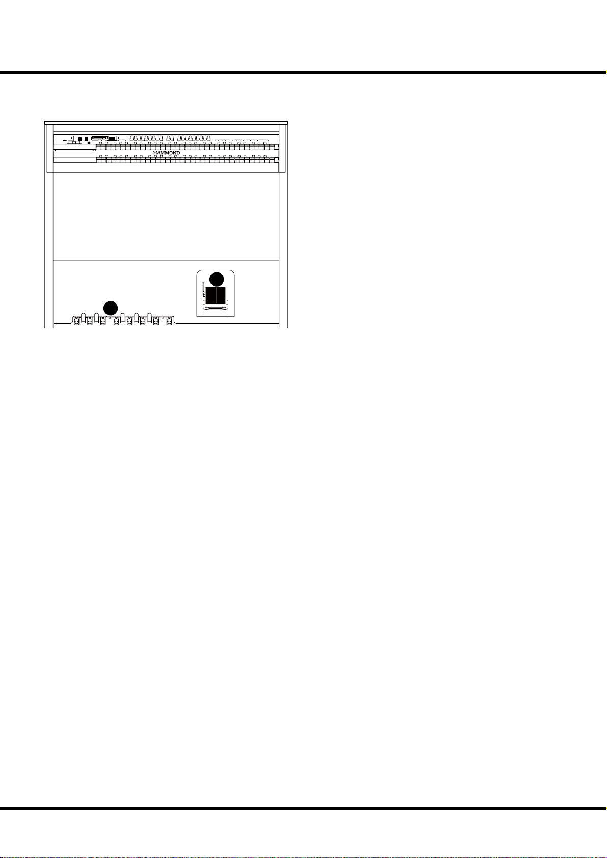
MAIN FEATURES
ACCURATELY REPRODUCES THE TONE-WHEEL SOUND
Your new A-405SP contains 96 independent oscillating digital tone-wheels that accurately
reproduce the sound of the Vintage B-3/C-3.
In addition, this organ has full polyphony
BUILT IN EXTRA VOICE
Such Extra Voices as the piano, strings, brass, wind, 880 instruments and 56 drum kits are
built in for producing realistic instrumental sound.
16 part multi-timbral GM upper compatible sound engine is included for reproducing
GM standard song data.
ADVANCED DIGITAL LESLIE / VIBRATO EFFECTS
e A-405SP is equipped with a DSP eff ect generator to simulate the Scanner-Vibrato
and Leslie Speaker. e range of sound that you can create is expanded by the use of
Vibrato and Chorus eff ects, and by the real sounding Leslie eff ects which eff ectively simulates the rotation of the two Rotors which are present in traditional Leslie Speakers.
EQUALIZER AND TONE CONTROL
A 3-band equalizer and tone-control are now built in. e equalizer can make fi ne or
course tonal adjustments to the bass, treble, and mid frequency ranges. e tone-control
simulates the circuit built in on the vintage B-3/C-3 pre-amp to obtain a gently-cut treble.
9
SEQUENCER WITH CompactFlash™ CARD SLOT
A sequencer is built in for recording the player’s performance. A Compact Flash card is
utilized to record the performance data.
MIDI MASTER KEYBOARD
An external zone is available on each manual and pedalboard to enable this organ to be
used as a master keyboard.
50W 2CH AUDIO AMPLIFIER
Built in a 50 watt Power Amp for each cahnnel of Left and Right.
us you can enjoy a dynamic play with the organ itself.
Introduction
Page 10
10
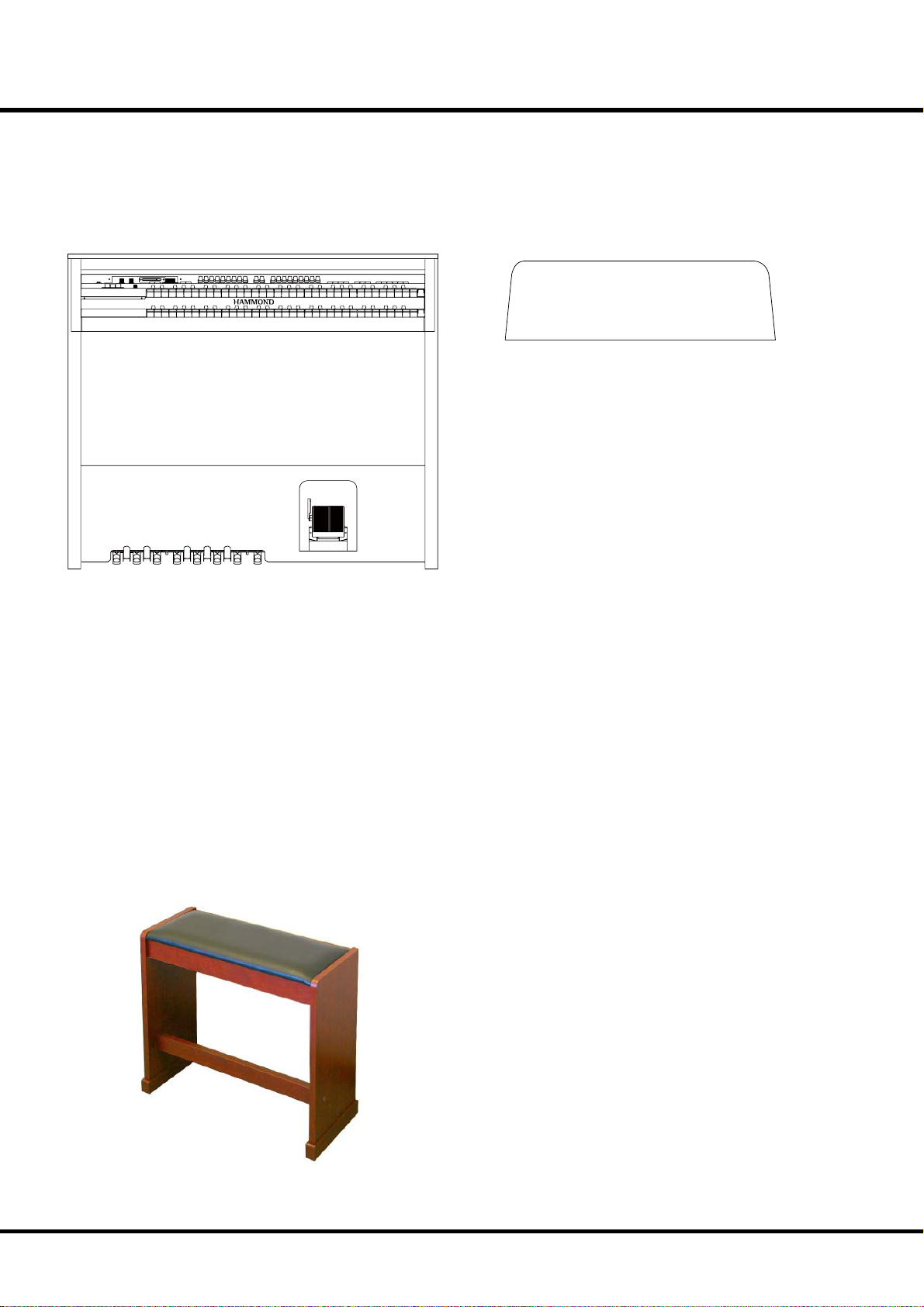
Components
HOW TO ASSEMBLE
Organ
Music Rack
Bench
*#1 #52
Owner’s Manual
Page 11
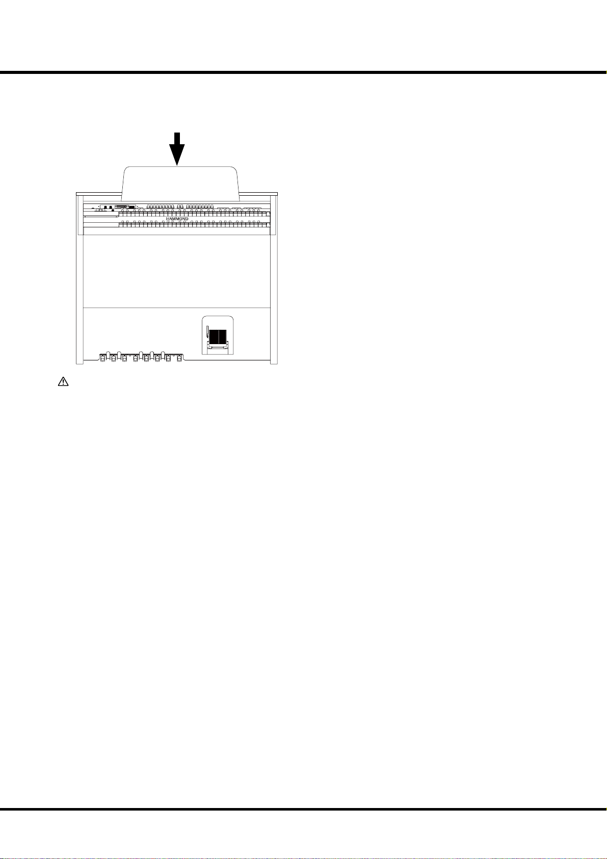
Put on the Music Rack
Insert the Music Rack into the rail whenever necessary.
11
ATTENTION
Do not excessive pressure on the music rack.
Introduction
Page 12
12
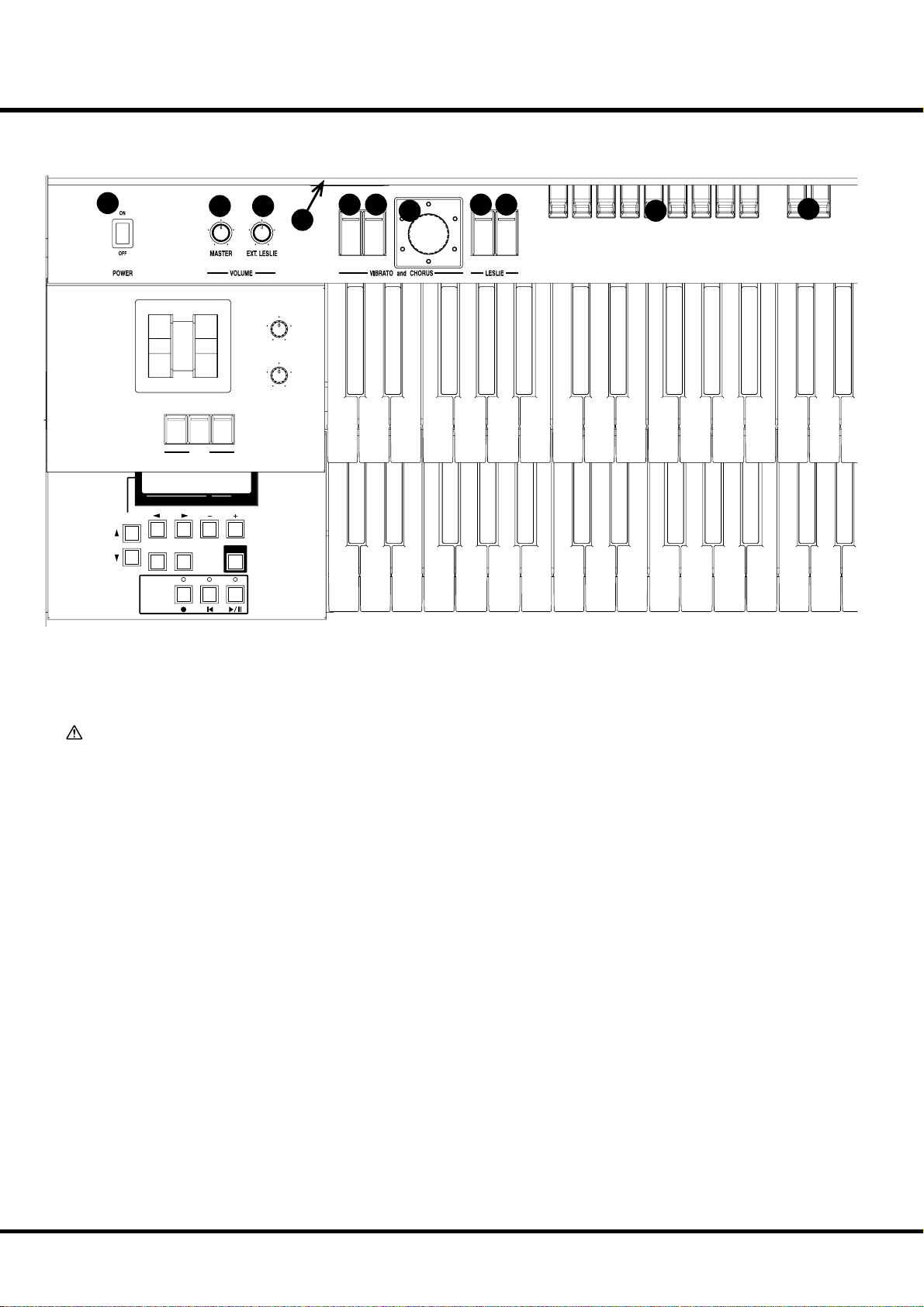
Top Panel
NAMES AND FUNCTIONS
1
PAGE/ PARAM.
SONG
2 3
PITCH BEND MODULATION
PEDAL
GREAT
PEDAL
TO
TO
SUSTAIN
GREAT
PEDAL
PEDAL
SWELL
PEDAL GREAT
TRANSPOSE
PRESET
1234
SEQUENCER
VALUE
4
REVERB
EXTRA VOICE
VOLUME
PLAYJUMPMENU
ON
SWELLONGREAT
5 6
V-3
7
VIBRATO
AND
CHORUS
LESLIE
LESLIE
ON
V-1V-2
C-1
FAST
10
8 9
C-3C-2
11
UPPER LEFT
1. POWER Switch
is switch turns the power ON and OFF. (P. 22)
CAUTION
Even when the POWER switch is turned o , electricity
is still owing to the instrument at the minimum level.
When you are not using the instrument for a long time,
make sure you unplug the power cord from the wall AC
outlet.
2. MASTER VOLUME Knob
Controls the total volume of internal speaker, headphones and
line out jack. (P. 22)
3. EXT. LESLIE VOLUME Knob
Controls the total volume of external Leslie Speaker.
4. CF Card Slot
Insert the CompactFlash™ Card here.
is is used to store the song and recall the rhythm style of this
organ. Use required CompactFlash™ Card. (P. 96)
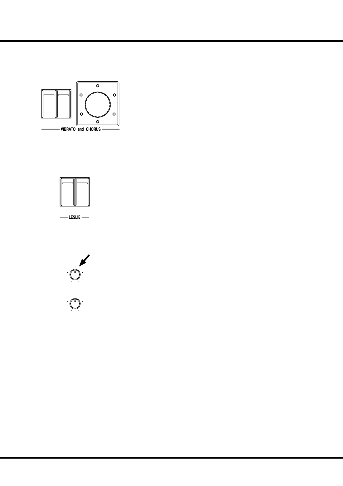
VIBRATO & CHORUS
5. SWELL ON Button
Switches on and off the Vibrato & Chorus Eff ects on the
SWELL Drawbar part. (P. 40)
6. GREAT ON Button
Switches on and off the Vibrato & Chorus Eff ects on the
GREAT Drawbar part. (P. 40)
7. VIBRATO & CHORUS MODE Knob
Changes the depth of Vibrato & Chorus Eff ects. (P. 40)
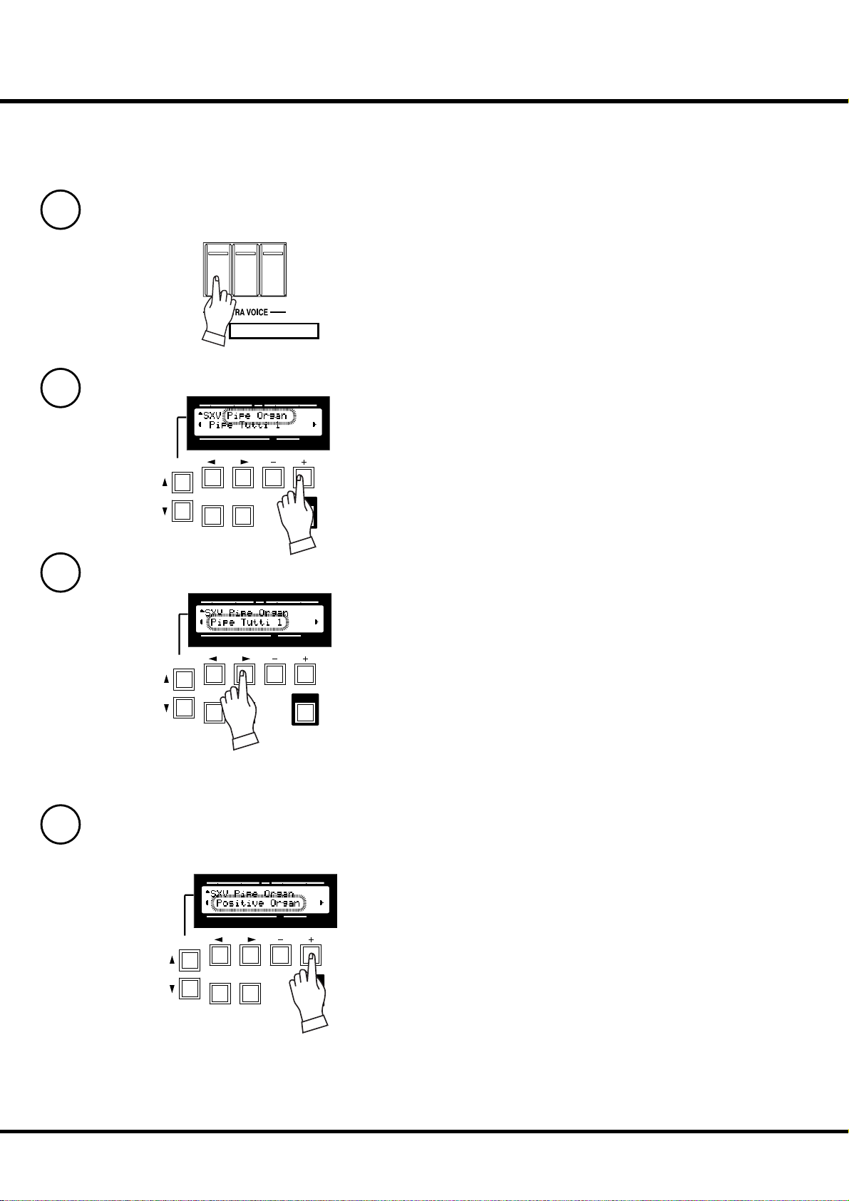
LESLIE
8. LESLIE ON Button
When it is turned ON, the rotor turns and the sound come
from the Rotor.
When the lamp is lighting, it is “ON”. (P. 41)
9. LESLIE FAST Button
Changes the speed of the Rotor from Slow to Fast and vice
versa. When the lamp is lighting, it is “Fast”. (P. 41)
DRAWBARS
10. SWELL DRAWBARS
Controls SWELL keyboard harmonics. (P. 34)
11. PEDAL DRAWBARS
Controls PEDAL keyboard harmonics. (P. 34)
12. GREAT DRAWBARS
Controls GREAT keyboard harmonics. (P. 34)
PERCUSSION
13. SECOND ON Button
Adds 4´ Percussion (decay sound) to SWELL keyboard. (P. 39)
14. THIRD ON Button
Adds 2⅔ ΄ Percussion (decay sound) to SWELL keyboard. (P. 39)
15. DECAY FAST Button
Changes decay time of Percussion. (P. 39)
*#1 #52
Owner’s Manual
Page 13
12
24
13 14
SECOND
THIRD
HARMONIC
HARMONIC
15 16
PERCUSS.
FAST
SOFT
DECAY
17 18 19
ON
ON
ON
GREAT
SWELL
PEDAL
20
BANK
1
2345
RECORD CANCEL
22
21
6789
23
13
25
16. VOLUME SOFT Button
Changes Percussion volume. (P. 39)
EXTRA VOICE
17. ON SWELL Button
Turns on/off the SWELL Extra Voice. (P. 28)
18. ON GREAT Button
Turns on/off the GREAT Extra Voice. (P. 28)
19. ON PEDAL Button
Turns on/off the PEDAL Extra Voice. (P. 28)
PRESETS
20. BANK Button
Switches Bank by pressing together the bank button with the
number buttons (#21). (P. 24)
21. NUMBER Buttons
Recalls the Preset or switches the Bank by using together BANK
button (#20). (P. 24)
22. RECORD Button
Records Presets. (P. 30)
23. CANCEL Button
Cancels Presets. Calls out the “CANCEL” setting.
e Drawbar registration and the actual one always agree. (P. 26)
KEYBOARDS
24. SWELL Keyboard
is is a keyboard with 61 notes, velocity-sensitive.
25. GREAT Keyboard
is is a keyboard with 61 notes, velocity-sensitive.
Introduction
Page 14

14
End Block
PITCH BEND MODULATION
26
30
PEDAL
TO
GREAT
SWELL
PRESET
1234
PAGE/ PARAM.
SONG
35
34
37
38 39
SEQUENCER
40
27
32
31
GREAT
PEDAL
TO
SUSTAIN
PEDAL
PEDAL
PEDAL GREAT
33
TRANSPOSE
VALUE
36
41
PLAYJUMPMENU
42
28
29
REVERB
EXTRA VOICE
VOLUME
select items #1 and #2 on the basic edit pages. (P. 48)
36. VALUE Buttons
is is used to increase or decrease values, also to select items
#3 and #4 on the basic edit pages. (P. 48)
37. MENU Button
is is for calling the MENU mode, Also for exiting from various function modes, and jump to function modes. (P. 48)
38. JUMP Button
is allows you to quickly call a pre-selected menu item directly. (P. 48)
39. PLAY Button
is selects the basic Play mode. (P. 48)
40. Button
is is used for recording your performance to the built-in Sequencer. (P. 98)
41. Button
is stops the built-in Sequencer and returns to the top of the
song. (P. 98)
42. Button
is is used to run the built-in Sequencer or pause it. (P. 98)
SWELL END BLOCK
26. PITCH BEND Wheel
Slides the pitch up or down.
e pitch goes up when moved up, and goes down when
moved down. (P. 62)
27. MODULATION Wheel
Adds modulation for Extra Voice section. (P. 62)
28. REVERB Knob
is is for adjusting the depth of the Reverb eff ects. (P. 42)
29. EXTRA VOICE VOLUME Knob
is is for controlling the volume of Extra Voice section. (P. 42)
30. PEDAL TO GREAT Button
is is for playing the PEDAL parts using GREAT keyboard.
(P. 43)
31. GREAT TO PEDAL Button
is is for playing the GREAT parts using PEDAL keyboard.
(P. 43)
32. PEDAL SUSTAIN Button
Adds sustain eff ect for PEDAL Drawbar part. (P. 43)
GREAT END BLOCK
33. Display
Various information is displayed here. (P. 48)
34. PAGE Buttons
Used to scroll through the various pages of controls and parameters. (P. 48)
35. PARAM Buttons
is is used for selecting the parameter item to edit, also to
*#1 #52
Owner’s Manual
Page 15
Manual Bottom
43
SEQUENCER
44
15
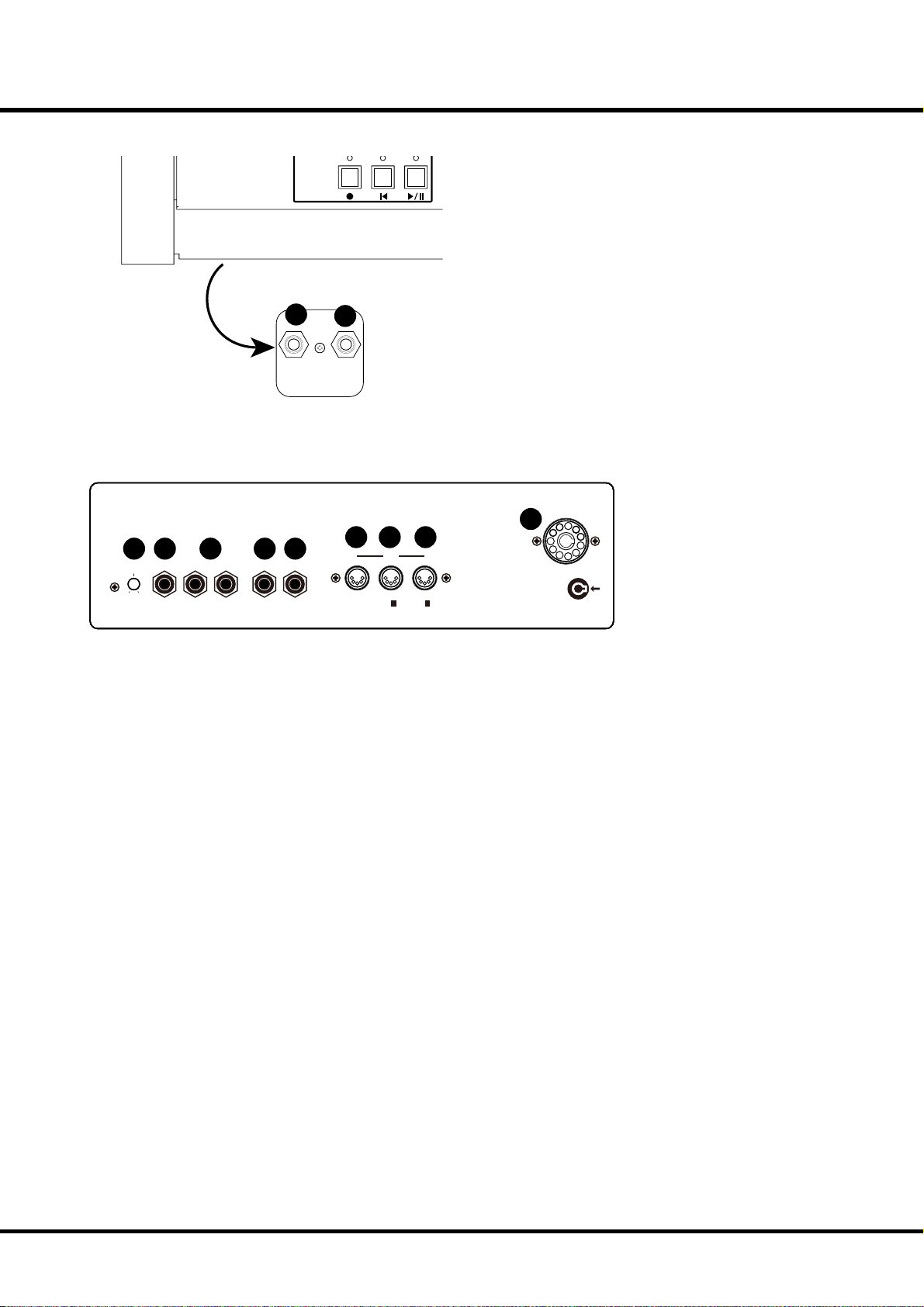
43. FOOT SWITCH Jack
is jack is for Foot Switch (= FS-9H - optional) and the Leslie
Switch (= CU-1 - optional).
You can switch the speed of the Leslie eff ect and the Combination Preset, etc. while playing. (P. 20)
44. HEADPHONES Jack
is is for connecting the stereo headphones. e speakers are
turned off , when a plug is inserted to this jack. (P. 19)
FOOT
SWITCH 2
HEAD
PHONE
Rear Panel
45 46 47 48 49
MICROPHONE LINE IN LINE OUT
MIN. MAX.
VOLUME IN L R L R
45. MICROPHONE VOLUME Knob
is adjusts the volume of the microphone (#46).
NOTE: The microphone volume can be adjusted with the MASTER
VOLUME (#2) and EXT. LESLIE VOLUME (#3) knob.
46. MICROPHONE Jack
If you plug a microphone into the this jack, you can use the this
organ as a public-address system.
NOTE: Feedback could be produced depending on the location of
microphone relative to speakers. This can be prevented by:
- Changing the position of the microphone.
- Relocating microphone at a greater distance from speakers.
- Lowering volume levels.
47. LINE IN L, R Jack
is is the input for an external sound module or a CD player.
e signals input to this jack are routed to the built-in speakers, LINE OUT jack, HEADPHONE jack, and the stationary
channel of Leslie Speaker.
NOTE: The line in volume can be adjusted with the MASTER VOLUME
(#2) and EXT. LESLIE VOLUME (#3) knob.
48. LINE OUT L Jack
is is the Left channel output of this organ.
49. LINE OUT R Jack
is is the Right channel output of this organ.
Use the Left and Right output jacks if your mixer or amplifi er
has a stereo input.
50. MIDI OUT Jack
Sends out the performance information of this organ. (P. 84)
50 51 52
MIDI
OUT
IN 1 IN 2
(KEYBOARD) (MULTI)
LESLIE 11PIN
53
51. MIDI IN1 (KEYBOARD) Jack
is jack is for playing the keyboard channels (SWELL,
GREAT, PEDAL) from external MIDI equipment. (P. 84)
52. MIDI IN 2 (MULTI) Jack
is jack is for playing the built-in 16 part multi-timbral sound
engine from external MIDI equipment. (P. 84)
53. LESLIE 11 PIN Socket
Connect the Leslie speaker here. (P. 18)
Introduction
Page 16
16
Pedals
54
54. EXPRESSION Pedal
is is for changing the total volume of the organ.
e Foot Switch is attached on the top left. (P. 25)
55
55. Pedalboard
13 notes. Flat type, non-velocity keyboard.
*#1 #52
Owner’s Manual
Page 17
17
HOOK-UP
Page 18
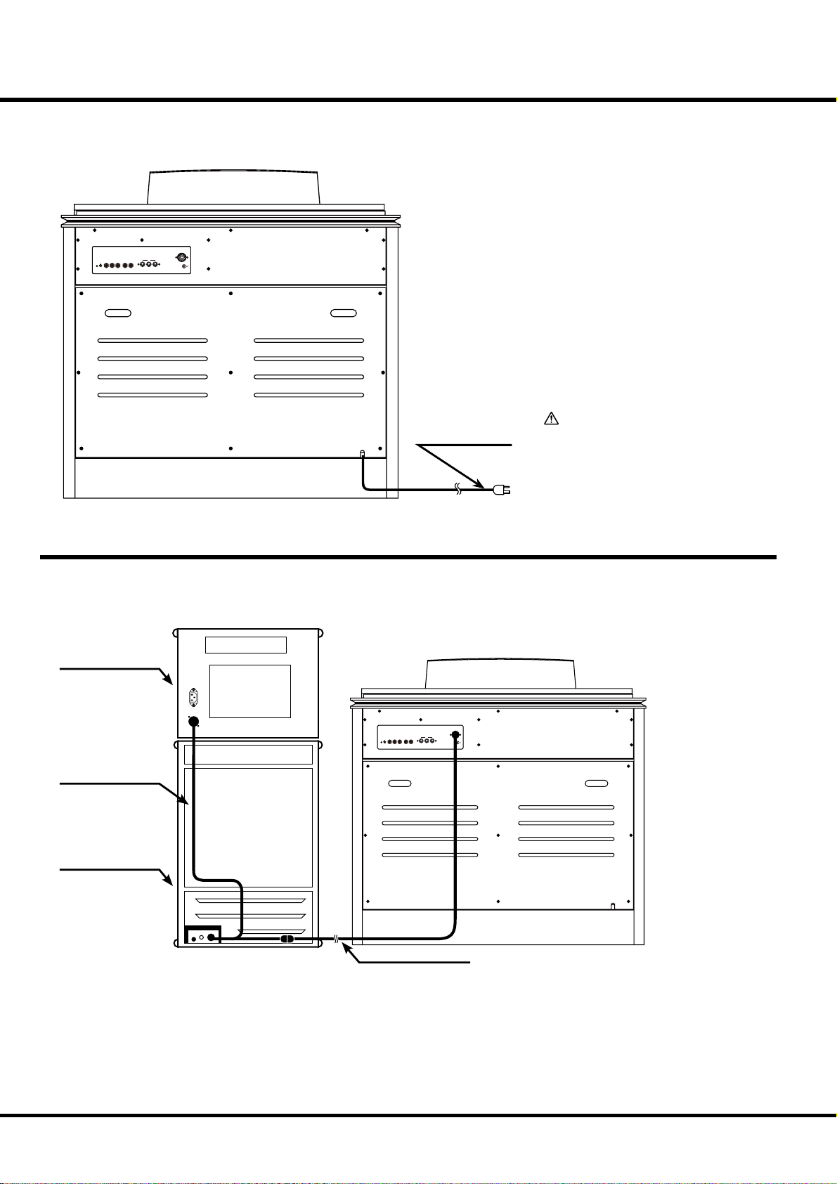
18
BASIC HOOK-UP
is organ has a built-in speaker system, so you can start playing immediately after
connecting to the power source by inserting the AC plug to the AC outlet.
LESLIE 11PIN
MICROPHONE LINE IN LINE OUT
MIN. MAX.
VOLUME IN L R L / MONO R
MIDI
OUT INTHRU
to AC outlet
CAUTION
Do not expose this organ to any excessive heat sources such as direct
sunlight or ames.
CONNECTING THE LESLIE SPEAKER
is organ is equipped with a 11-pin Leslie connector, so you can directly connect
the Leslie Speaker.
Make this connection with the Organ power OFF.
Leslie Stationary Unit
LESLIE 11PIN
MIDI
OUT INTHRU
Leslie “Y” Cable
Leslie Rotary Unit
MICROPHONE LINE IN LINE OUT
MIN. MAX.
VOLUME IN L R L / MONO R
Standard 11-pin Cable
Connect the Leslie Speaker to the 11-pin terminal on the organ, with the exclusive 11-pin Leslie Cable (to be separately
purchased - with the other Leslie Speaker accessories).
Adjust the setting of the “EXT. LESLIE CH”, in accordance
with the Leslie Speaker connected. (P. 72)
*#1 #52
Owner’s Manual
eg. Typical Leslie Speaker Channel
122XB, 3300/W -- 1CH
2101/mk2, 3300/3300W with Stationary Unit -- 3CH
Please carefully read the User’s Guide of the Leslie Speaker.
Page 19
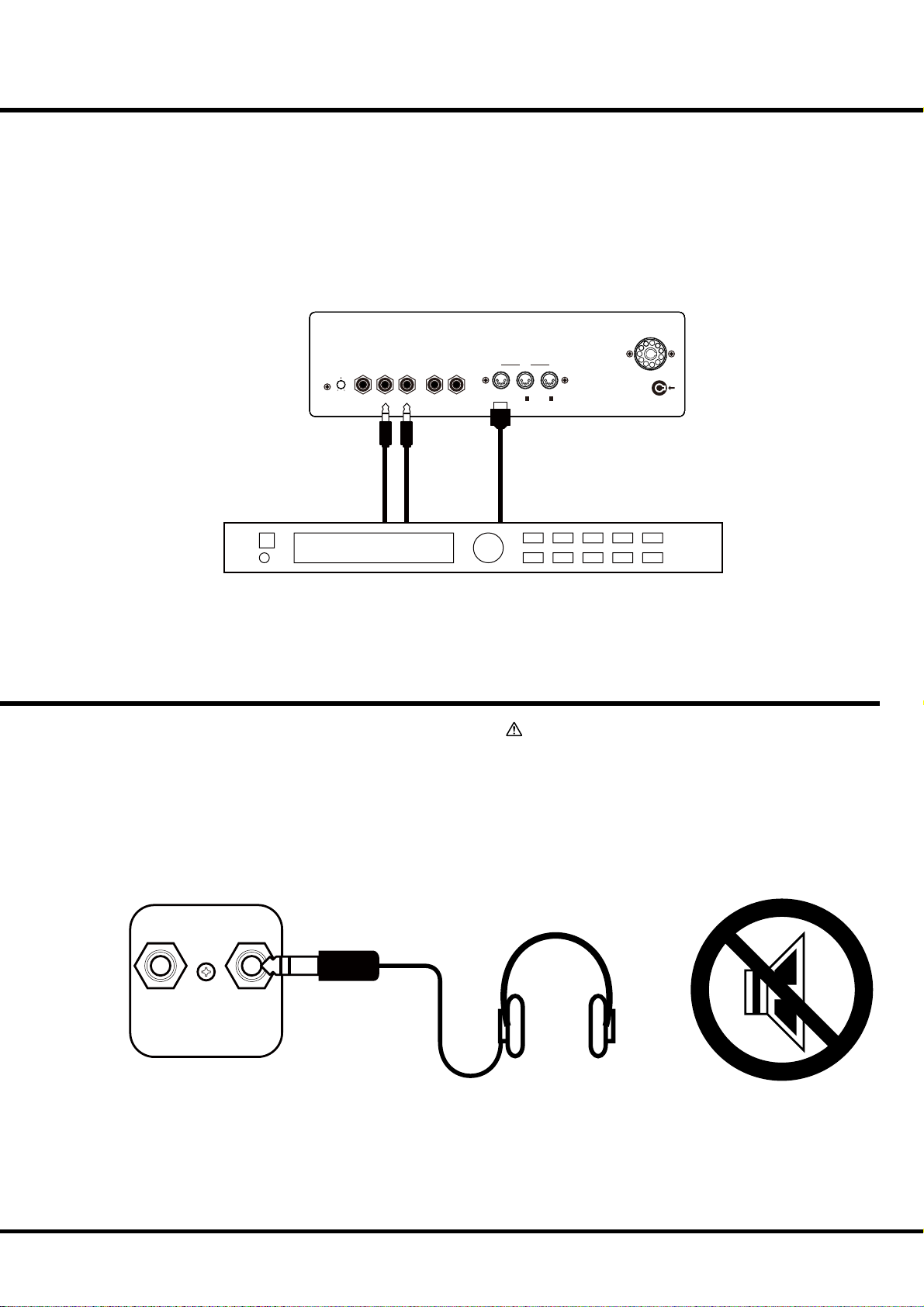
USING A MIDI SOUND MODULE
Each Manual and the Pedalboard on this organ has a External Zone for controlling external MIDI sound modules. When Connected to the LINE IN jacks, the external MIDI
sound module output is sent to the built in speakers, stationary channel of the Leslie
terminal (on a so-equipped Leslie), the LINE OUT jack and the headphone jack.
NOTE: Adjust the volume of the equipment connected to the LINE IN jack on the external equip-
ment itself.
19
LESLIE 11PIN
MICROPHONE LINE IN LINE OUT
MIN. MAX.
VOLUME IN L R L / MONO R
LINE OUT MIDI IN
MIDI Sound Module
USING HEADPHONES
You can practice silently by connecting the stereo headphones
to the HEADPHONE jack of this organ.
When the plug is inserted to the HEADPHONE jack, the
built-in / external Leslie speakers are silenced.
MIDI
OUT
IN 1 IN2
(KEYBOARD) (MULTI)
ATTENTION
Hold the molded part of the plug of the cord when you
connect or disconnect it to avoid the risk of breaking
the cable.
Do not use excessive volume with headphones, due to
risk hearing damage.
FOOT
SWITCH 2
HEAD
PHONE
Hook-Up
Page 20
20
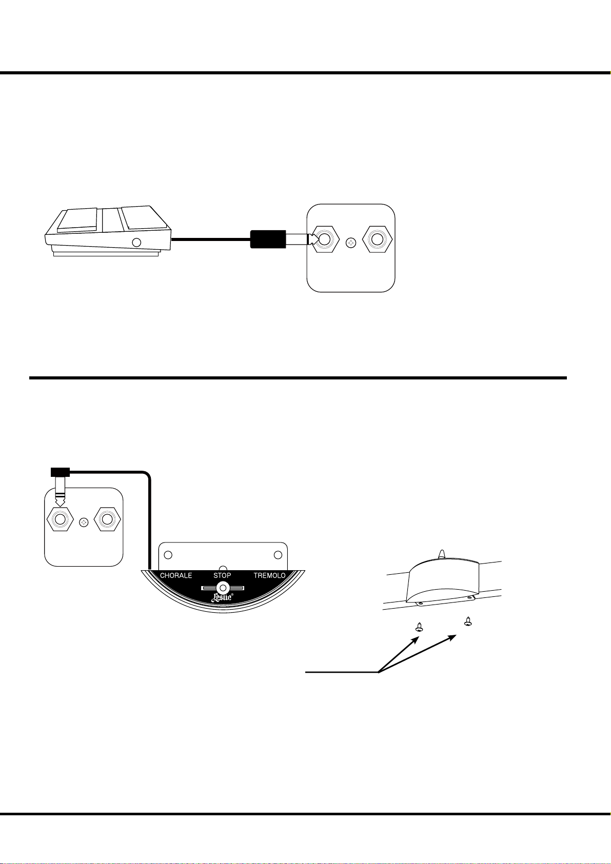
USING AN EXTERNAL FOOT SWITCH
is organ has a foot switch attached to the Expression Pedal. If necessary, you
may also add an external foot switch to it. In that case, connect an unlatchtype foot switch to the “FOOT SWITCH” jack on the underside of the key
bed. e Hammond FS-9H (optional) is recommended.
e “FOOT SWITCH” jack is tip-ring-sleeve. So you may connect a twinpedal-type foot switch with a stereophonic plug to this jack.
After this connection, set the FOOT 2 DEVICE at “PEDAL” in the “CONTROL - FOOT SW” mode. (P. 63)
FOOT
SWITCH 2
HEAD
PHONE
USING A LESLIE MODE SWITCH
You may connect the traditional ‘half-moon type’ Leslie speed Switch to this organ for
switching the Leslie mode as if a B-3/C-3. Mount the CU-1 (optional) on the front
of the GREAT manual and then connect the plug to the “FOOT SWITCH” jack.
After this connection, set the FOOT 2 DEVICE to “CU-1” in the CONTROL FOOT SW” mode. (P. 63)
FOOT
SWITCH 2
HEAD
PHONE
*#1 #52
Self-tapping Screw
ø4 x 16mm
Owner’s Manual
Page 21

21
TURN ON AND
PLAY
Page 22

22
How to power on
SWELL
PEDAL GREAT
PRESET
1234
PAGE/ PARAM.
SONG
TRANSPOSE
VALUE
PLAYJUMPMENU
POWER ON
After connecting your A-405SP to the power outlet, please perform the following procedure
before switching on the power. To avoid possible damages to speakers, please do not vary the
procedure.
STEPS TO TAKE
1. Set the [MASTER VOLUME] knob at 0 (minimum), before switching the power on.
2. Switch on the [POWER] on the top panel. “PLAY” mode appears, following the TITLE,
in the Display window.
The circuit protection devices create a few second delay before the A-405SP is ready
to play.
3. Switch on the power of the external amplifi ers etc. connected to the A-405SP.
4. Holding down a key, adjust the [MASTER VOLUME] by turning the knob.
The Preset button [CANCEL] does not produce sound when initially rst turned on.
Draw the Drawbars, or press either of the Preset Buttons [1] - [9] to start.
5. Adjust the volume of the amplifi ers etc.
Reverse the above steps when you switch o the power . (Switch o the power of the
ampli ers etc. rst.)
SEQUENCER
Switch-off memory
Your A-405SP memorizes the setting of the organ immediately before it is switched off . So,
the organ will start with these settings when it is switched on again.
e A-405SP is initially shipped from the factory with the Preset Button [CANCEL] in
“pressed” status.
Reset to the initial status
Please perform the following steps to reset the A-405SP to the initial default setting.
STEPS TO TAKE
1. Switch off the power of the A-405SP.
2. Holding the [RECORD] button, switch on the power.
3. Hold down / keep pressing the [RECORD] button until “Loading Default...” appears
on the Display.
4. If everything is in order, “PLAY” mode appears on the Display. (Completed)
*#1 #52
Owner’s Manual
Page 23

LISTEN TO THE DEMONSTRATION PERFORMANCE
1
PITCH BEND MODULATION
23
2
PEDAL
TO
GREAT
SWELL PEDAL GREAT
SWELL
PRESET
PAGE/ PARAM.
SONG
1234
GREAT
PEDAL
TO
SUSTAIN
PEDAL
PEDAL
PEDAL GREAT
REVERB
EXTRA VOICE
VOLUME
TRANSPOSE
VALUE
Touch and hold the [PEDAL TO GREAT] and [GREAT TO
PEDAL] Buttons for 2 seconds.
e Display will be as shown in step 2.
NOTE: You can locate this mode another way. Touch the [MENU]
Button to display the MENU, touch the [PAGE] Button and
select page F, and touch the [1] DEMO.
Press the [PAGE] Button and select a desired song.
e performance starts when the [4] “X” Button is pressed.
NOTE: After the song is over, the next one starts automatically.
To select a new song while you are playing, touch the [3] “”
Button. e performance that is playing will stop.
NOTE: You can not operate the controllers while playing the dem-
onstration, except [MASTER VOLUME], [EXT. LESLIE VOLUME], [LESLIE ON], [LESLIE FAST] and [VIBRATO & CHORUS].
3
SWELL
PRESET
PAGE/ PARAM.
SONG
1234
PEDAL GREAT
TRANSPOSE
VALUE
PLAYJUMPMENU
If you press the [PEDAL TO GREAT] and [GREAT TO
PEDAL] Button for 2 seconds, press the [MENU] or [PLAY]
Button, the performance stops.
PLAYJUMPMENU
Turn On And Play
Page 24
24
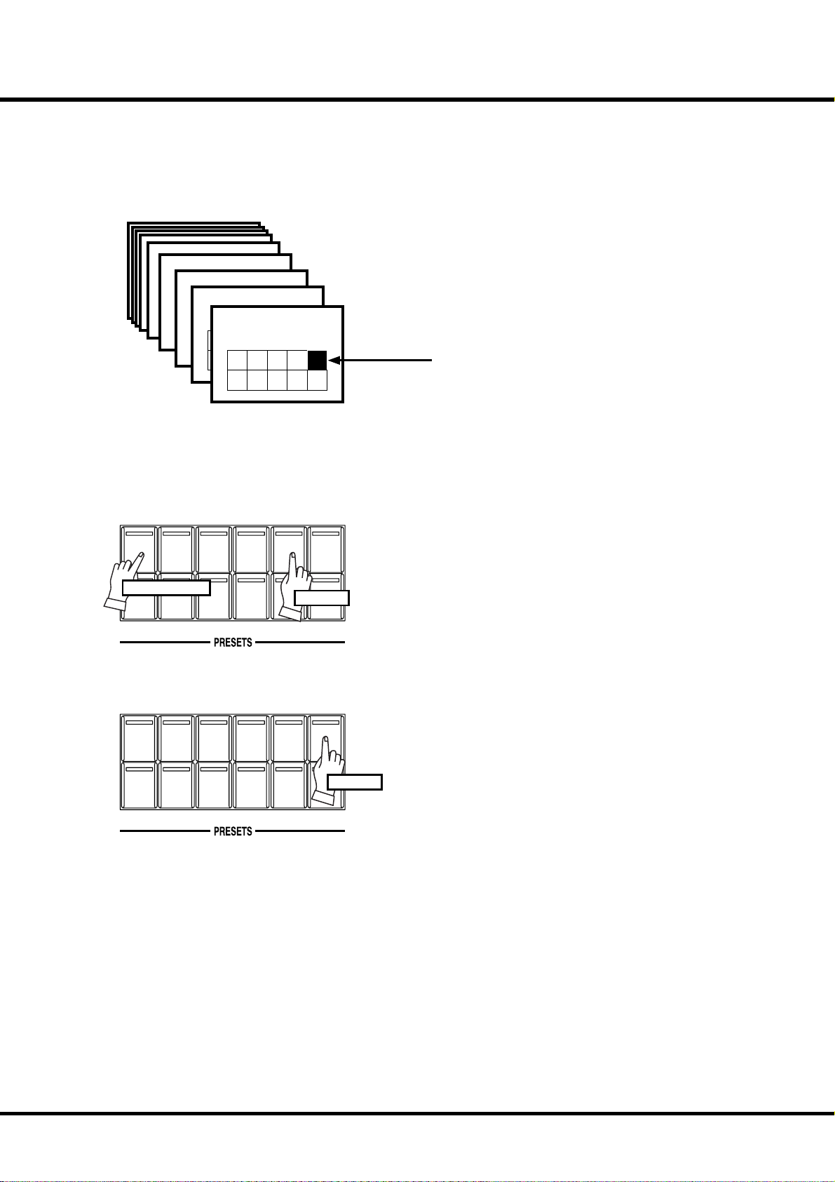
PLAY WITH THE COMBINATION PRESETS
You can record various settings to the Preset buttons mounted on the right-hand side of
the top panel. is is called “Combination Preset”.
e Combination Preset consists of the “BANK” and “NUMBER” such as “3-2”, and
appears for each setting on the Display.
Bank 3
Bank 2
Bank 1
Bank 9
Preset Number
Bank 8
Preset Number
Preset Number
Preset Number
Bank 7
1 2 3 4 5
Preset Number
1 2 3 4 5
1 2 3 4 5
Bank 6
1 2 3 4 5
Preset Number
6 7 8 9 C
1 2 3 4 5
6 7 8 9 C
6 7 8 9 C
6 7 8 9 C
How to recall the Preset
Bank 5
Preset Number
1 2 3 4 5
6 7 8 9 C
Preset Number
Bank 4
1 2 3 4 5
6 7 8 9 C
1 2 3 4 5
Preset Number
6 7 8 9 C
6 7 8 9 C
1 2 3 4 5
6 7 8 9 C
e chart on the left is for the Combination Preset.
e example below recalls this.
Ex. Select 4-5
RECORD CANCEL
RECORD CANCEL
BANK
BANK
1
Press and Hold
6789
1
6789
2345
Touch
2345
Touch
1. Select the BANK
While holding down the [BANK] button, press the Number
button [4].
NOTE: The LED for the Number button indicates the “BANK”, while
the [BANK] button is pressed.
2. Select the NUMBER
Press the Number button [5].
At this time the Preset is decided and the setting changes.
NOTE: While the [BANK] button is released, the LED indicates the
“KEY”.
“4-5” appears on the bottom left of the Display.
Recall various Combination Presets and play.
When you recall a Combination Preset, not only Drawbars but
also the Eff ects such as Leslie and Reverb change altogether.
However, the BANK 1 of the factory setting changes only the
Drawbars. is action is the same as on B-3 or C-3.
NOTE: You can set the types of the Parameter you recall (P. 60).
*#1 #52
Owner’s Manual
Page 25
PLAY WITH THE CONTROLLERS
Using the performance controllers will add expression to your playing. On this page you will learn how to
use these controllers. e controllers exclusive to the Hammond are covered on the next page.
Pitch Bend / Modulation Wheel
25
PITCH BEND MODULATION
Expression Pedal
e [PITCH BEND] wheel is used to slide the pitch up or down
while playing.
e frequency goes up when you move it back, and it goes down
when you move it forward.
When you release your hand from the [PITCH BEND] wheel, it
returns automatically to the center position.
NOTE: You can adjust the range of the pitch bend. (P. 62)
e [MODULATION] wheel on the right is not usually used with
the Hammond Organ Drawbar voices. It is used when you modulate Extra Voice or External Zones.
e organ’s volume is controlled by using the Expression Pedal.
As you depress the pedal forward, the volume rises, and lowers
when you return it.
NOTE: You can adjust the range of the expression pedal. (P. 63)
Foot Switch
e Foot Switch, on the left side of the Expression Pedal can be
programmed for various functions. “Leslie Slow / Fast - Alternate”
is the factory default. Every time you depress the Foot Switch, the
Leslie changes mode.
NOTE: You can change the Foot Switch assignment. (P. 64)
NOTE: You can add external Foot Switch or Leslie Mode switch. (P. 64)
Turn On And Play
Page 26

26
TRY MAKING YOUR OWN SOUND
You will be able to produce your own sound by using the exclusive features of your Hammond Organ, such as Drawbars, Percussion, Vibrato & Chorus, Leslie eff ects, and Reverb.
Let’s go through the fi rst steps:
Select the Preset Button [ CANCEL]
BANK
1
2345
RECORD CANCEL
6789
Touch
Pull out the SWELL Drawbars
C-3
LESLIE
LESLIE
ON
FAST
V-1
Select the Preset Button [CANCEL] fi rst.
e Preset Button [CANCEL] makes all of the front panel
controls (Drawbars, Tabs, etc.) current, and sounding at their
physical position. is setting is used to create registrations “on
the fl y”. It could also be referred to as “Manual” mode.
NOTE: You can initialize the contents to the default setting (P. 81 #1)
Pull out the SWELL Drawbars on the left-hand side to your
desired length, pressing a key on the SWELL keyboard to the
certain.
e tone varies corresponding to the extent or the length of the
Drawbar. It is the Drawbars that create the fundamental tones
of this organ.
e volume gets louder as each Drawbar is pulled out to the
full length. e sound gets silent when it is totally pressed back.
e tones of the Drawbars gradually get higher in frequency
from left to right.
e most popular patterns or registrations are (1) to pull out
only all the three left side Drawbars to the full, (2) to pull the
far-left and only the white bars to the full, or (3) to pull all the
bars.
NOTE: You can change the characteristics of the Drawbars (P. 58).
NOTE: The present registration is shown on the “Play” mode display
(P. 49).
Add Percussion
SECOND
THIRD
HARMONIC
HARMONIC
*#1 #52
PERCUSS.
FAST
SOFT
DECAY
Owner’s Manual
e “Percussion” referred to here is not a percussion instrument
itself, but it is a “decay” to add a clear-cut “attack” to the organ sound. You can add this “attack” to mix with the Drawbar
sound when you want.
If you turn on the [SECOND], [THIRD] buttons, decays of
the harmonic overtones (= one octave higher “C” and “G”) are
added.
If you turn on the [FAST] button, the percussion sounds fades
quickly. Pressing the [SOFT] button reduces the volume of the
Percussion sound.
NOTE: You can do ne volume setting etc. of the Percussion (P. 69).
Page 27
Add effects
27
Vibrato & Chorus
ON
SWELLONGREAT
Leslie
LESLIE
ON
LESLIE
FAST
VIBRATO
AND
CHORUS
V-3
C-1
“Vibrato & Chorus” slightly changes the Drawbar pitch at a certain ratio and adds
warmth to the sound.
C-3C-2
V-1V-2
[ON SWELL], [ON GREAT] Button
Switches the Vibrato eff ect off and on. e LED illuminates when ON.
[VIBRATO & CHORUS MODE] Knob
Selects Chorus or Vibrato and the depth of each.
e degree of depth corresponds with the number.
NOTE: You can nely adjust the speed etc. of the Vibrato & Chorus. (P. 74)
A digital LESLIE™ Eff ect with virtual “horn” and “rotor”, duplicating the eff ect of the
classic electro-mechanical Leslie™.
[ON] Button
Switches on the eff ect. When “On”, the LED will light.
[FAST] Button
is button controls the rotor at two diff erent speeds. When the LED is ON, it is
FAST. When the LED is OFF, it is SLOW. e most eff ective and popular way to use
this is to mainly play SLOW while switching to FAST at phrases end, or for emphasis
FAST.
NOTE: These switches will also control as outboard genuine “Leslie” speaker.
NOTE: The speed, tonal characteristics and other parameters of the Digital LESLIE™ are easily
adjustable. (P. 70)
Reverb
e reverb eff ect simulates performing in a concert-hall.
[REVERB] Knob
Controls the depth of the Reverb eff ect. At full left the Reverb eff ect is off . e eff ect
REVERB
EXTRA VOICE
VOLUME
is organ has also built-in eff ects such as Overdrive(P. 74)and Equalizer(P. 78). See the details on these pages.
deepens as you rotate the knob.
NOTE: You can ne-control time etc. of Reverb. (P. 79)
Turn On And Play
Page 28
28
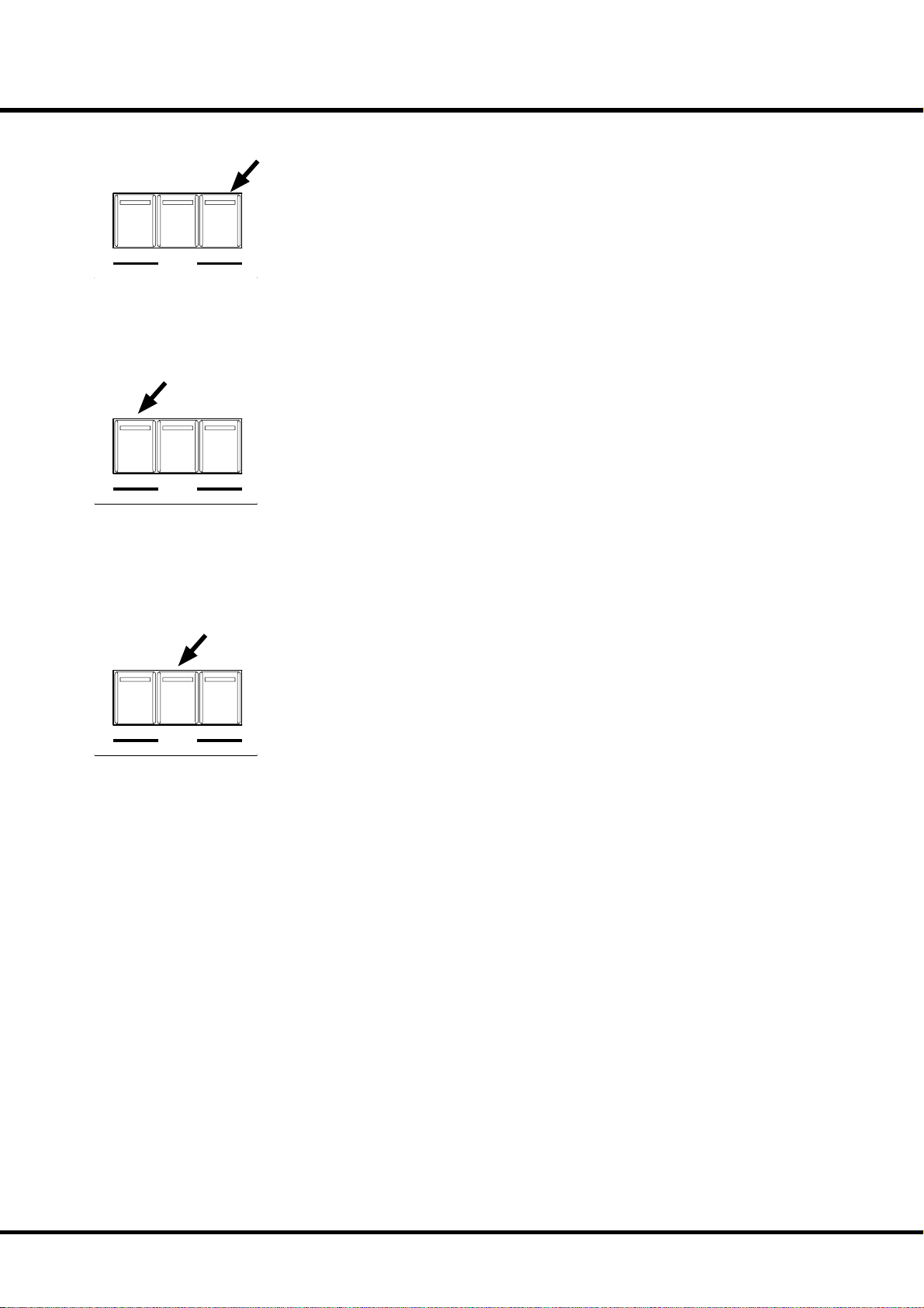
Using Extra Voice
Ex. Use “Positive Organ” for SWELL
1
ON
ON
ON
GREAT
SWELL
PEDAL
Hold down the [ON SWELL] button in the EXTRA VOICES
section for a few seconds. As soon as the button turns on, the
voice selecting page of the Extra Voice SWELL appears in the
display.
2
3
Press and Hold
SWELL
PEDAL GREAT
PRESET
1234
PAGE/ PARAM.
SONG
SWELL
PRESET
1234
PAGE/ PARAM.
SONG
TRANSPOSE
VALUE
PEDAL GREAT
TRANSPOSE
VALUE
To turn on/off the Extra Voice, just touch the [ON SWELL]
button.
Select the group (“Pipe Organ” this time) with the [VALUE]
button.
PLAYJUMPMENU
Press the [PARAMX] button and move the cursor to “Instrument”.
PLAYJUMPMENU
4
PAGE/ PARAM.
SONG
*#1 #52
SWELL
PEDAL GREAT
PRESET
1234
TRANSPOSE
VALUE
PLAYJUMPMENU
Owner’s Manual
Select the instrument (“Positive Organ” this time) with the
[VALUE] button.
Press the [PLAY] button to return to the PLAY mode.
Page 29
Pedal Sustain
PEDAL
GREAT
TO
PEDAL
PEDAL
SUSTAIN
TO
GREAT
PEDAL
Pedal To Great
PEDAL
GREAT
TO
PEDAL
PEDAL
PEDAL
SUSTAIN
TO
GREAT
29
e Pedal Drawbar sound can be set to smoothly decay after the key is released. is is called
“PEDAL SUSTAIN”.
To use this “Pedal Sustain” function, switch ON the [PEDAL SUSTAIN] button.
If you release your foot off the Pedalboard (or your fi nger from the GREAT keyboard , if
you are using the Pedal to Great, as explained later in this manual), the Pedal Drawbar sound
smoothly decays.
NOTE: You can change the decay time of the Pedal Sustain. (P. 59 #10)
You can play Bass using the lowest keys of the GREAT keyboard. is is called “Pedal To
Great”.
To use this “Pedal To Great” function, switch ON the [PEDAL TO GREAT] button.
When you playing the GREAT keyboard, the lowest note played will be sounded by the
Pedal Parts.
e factory default Pedal To Great range is set to “C” of the third octave.
NOTE: You can set the upper key limit of the Pedal To Great. (P. 65 #31)
Great To Pedal
PEDAL
GREAT
TO
PEDAL
PEDAL
PEDAL
SUSTAIN
TO
GREAT
You can play GREAT Parts using the Pedalboard. is is called “Great To Pedal”.
To use this “Great To Pedal” function, switch ON the [GREAT TO PEDAL] button.
When you playing the Pedalboard, the note played will be sounded by the GREAT Parts.
e factory default Great To Pedal range is set to “C” of the third octave.
NOTE: You can set the upper key limit of the Great To Pedal. (P. 65 #32)
Turn On And Play
Page 30
30
Storing registrations in Combination Preset
Ex. Memorize to “6-2”
1
Press and Hold
BANK
RECORD CANCEL
Light
1
2345
6789
Touch
While pressing the [BANK] button, press the Number button
[6].
e LED on the Number button indicates BANK while the
[BANK] button is pressed.
NOTE: The LED goes out if you release the button. This means the
Number is not nal.
2
Flash to On
BANK
1
2345
RECORD CANCEL
6789
Press and Hold
Touch with...
While pressing the [RECORD] button, press the Number button [2].
e Number is fi nalized and “Recording Preset” appears on
the Display while the process completes. When the recording
is completed, the LED on the Number button [2] fl ashes for a
few seconds and then switches on. e Display returns to the
previous mode.
e recorded Preset will be automatically selected.
NOTE: The Preset Data is preserved after power o .
*#1 #52
Owner’s Manual
Page 31

31
SETTING UP
Page 32

32
SOUND ENGINE STRUCTURE
Pedalboard
Pedal
Drawbars
Pedal
Virtual
Tonewheel
Set
Great
Drawbars
Great(Lower)
Manual
Great&Swell
Virtual
Tonewheel
Set
Swell(Upper)
Manual
Percussion
Swell
Drawbars
Expression
Extra Voice
Generator
Vibrato & Chorus
TC & Equalizer
Expression
switchable
Leslie
Simulator
Reverb
Overdrive
Reverb
Speakers
Line Out
Equalizer
Leslie 11Pin
*#1 #52
Chorus
Owner’s Manual
Page 33

To fully enjoy playing this organ, please read the following section in this manual.
See the illustrated system structures of this organ on the left page.
33
TONE-WHEELS
e sound source or “engine” of Hammond Organ are the virtual Tone-wheels. ey are
like the strings and pick-ups on the electric guitar. While running, each of the 96 virtual
Tone-wheels oscillates at a diff erent frequency.
KEYS
e keyboards of the A-405SP are traditional 61-note organ keyboards, using the inclined and overhanging confi guration. is is the same as fi ne church pipe organs, while
retaining the quick response traditional of Hammond Organs.
DRAWBARS
e Drawbars select the basic sounds. Each bar adjusts the value of each harmonic.
PERCUSSION
e Percussion adds a sharp accent to the drawbar sounds. is is the same “Touchresponse” Percussion section as found on the classic B-3/C-3.
VIBRATO & CHORUS
Vibrato raises and lowers the drawbar pitch slightly, at an even and adjustable depth and
speed. e Chorus “doubles” the sound with the duplicate slightly sharp. is creates a
distinct richness, and is an essential part of the genuine Hammond tone.
NOTE: On the classic B-3/C-3 the chorus/vibrato e ect was obtained by an electro-mechanical
“scanner”. The A-405SP uses a digital model of that scanner, that gives an accurate reproduction of the original.
OVERDRIVE
Overdrive adds the fuzzy, raspy, “dirty” sound created by the vacuum tubes of a tubestyle Leslie Speaker when its volume is pushed past its sound limit.
e PEDAL Part, however, is designed not to pass through the Vibrato & Chorus or the
Overdrive, in order to obtain a clear Bass-line.
TONE-WHEEL SET
The Tone-wheel Sets are divided into the
Manual Keyboard and the Pedalboard. This
is to give the Pedalboard the Decay (= the
sound gradually fading out while pressing the
key) or Sustain e ect (= the sound gradually
fading out after the key is released).
HARMONICS
Harmonic is a pitch of a di erent ratio to a certain pitch; for example, the one octave higher
C to the middle C. The more Harmonics, the
brighter and richer sound is obtained.
EQUALIZER, LESLIE and REVERB
e Organ signal passes through: the Equalizer (for tone regulation), the Leslie simulator (for the rotating speaker eff ects) and the Reverb (for resonance).
If a physical Leslie speaker is connected to it, the sound of the Leslie simulator is output
from the built-in speaker, and a dry sound from the 11-pin socket.
EXTRA VOICE
e Extra Voice section has its own DSP unit (Reverb, Chorus, and Equalizer) which is
independent of the 96 virtual tone-wheel generator.
Setting Up
Page 34

34
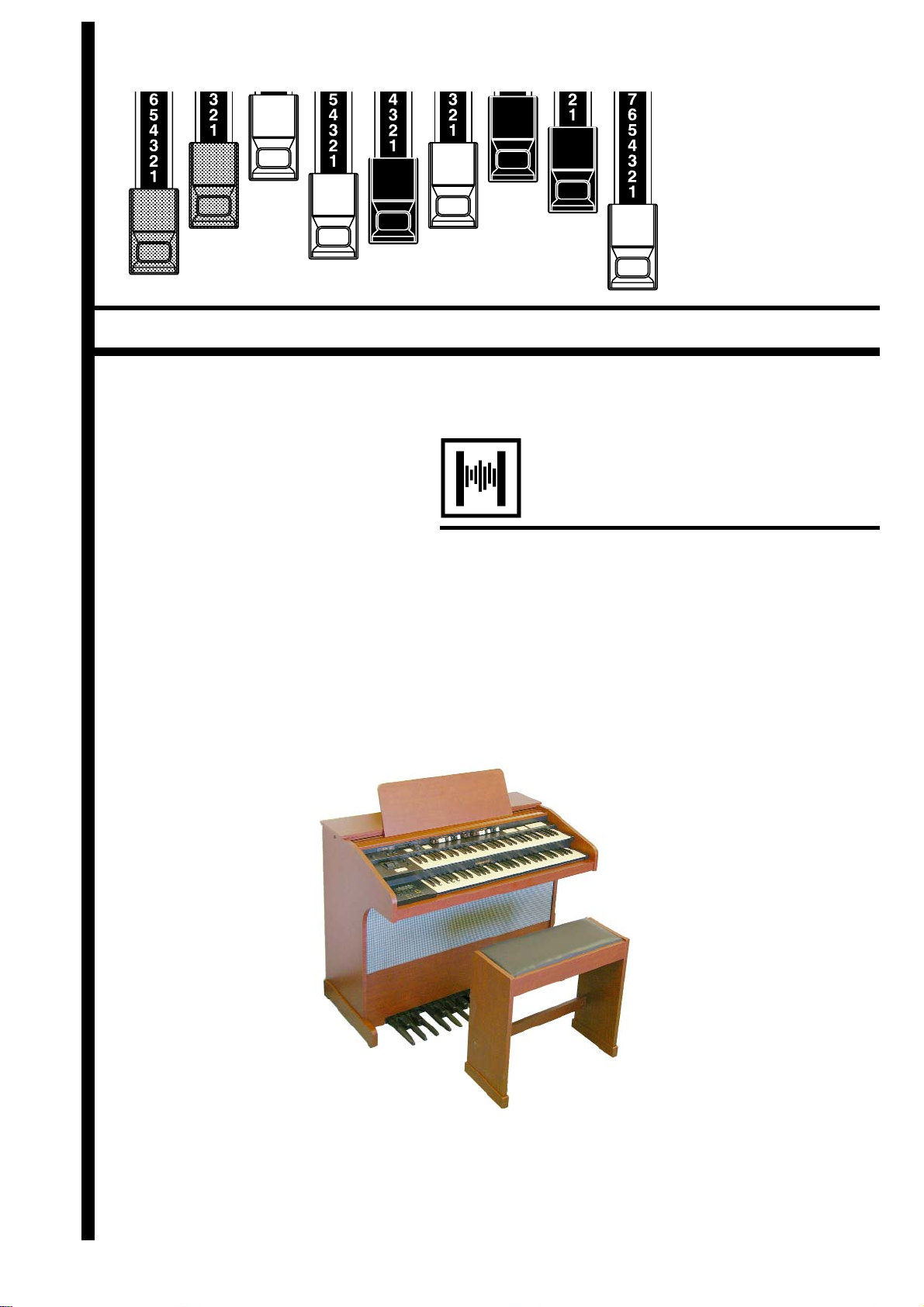
HARMONIC DRAWBARS™
e 9 Drawbars for each keyboard (plus 2 for the Pedal) of the A-405SP organ are
used to make the basic sounds. Each Drawbar is marked with the numbers 1 - 8. If
you push back the Drawbar until you can not see any number at all, the sound of
the Drawbar is not heard. If you pull it out to the fullest position the sound level is
maximum.
Except when the Preset button is [CANCEL], the actual Drawbar Registration is
the value displayed in the (display-)window. e “Drawbar Registration” shows the
length of the pulled-out Drawbar(s). e display shows only the Drawbar(s) you
operate.
16' 8' 4'
51/3'
22/3'
2'
13/5'11/3'
1'
Middle “C”
e pitch of each Drawbar is as shown above, when the middle C is depressed. e
footage marked (´) on each Drawbar is originated from the length of the pipes of a
pipe organ.
e numbers 1 - 8 on each Drawbar indicate the volume of the sound to be produced
as well as the guide to set the Drawbar.
For example, when you play a clarinet, the internal air vibrates, and the fundamental
(8´) and the third harmonic (2⅔ ´) plus the fi fth harmonic (1⁄´) are the basic components of the tone. On the A-405SP (or any Hammond Organ), if you pull out these
3 Drawbars, you can get a clarinet-like sound. If you pull out the 1⁄´ Drawbar and
push in the 8´ Drawbar a little shorter, the element of the high pitch increases and a
“hard” sound results. Conversely, if you pull out the 8´ one a little longer, the sound
gets mellower.
e millions of combinations possible allow you to make delicate changes to the
sound, depending on the fl ow of the tune or your choice, by fully utilizing the Drawbars.
NOTE: You can change the characters of the Drawbars. (P. 58)
*#1 #52
Owner’s Manual
Page 35

Manual Drawbars
35
White Drawbars
16' 8' 4'
51/3'
Black Drawbars
16' 8' 4'
51/3'
22/3'
22/3'
2'
2'
13/5'11/3'
13/5'11/3'
1'
In each Drawbar set, the white Drawbar (8´) plays in the basic
octave of the organ. e other drawbar pitches are fi gured in
reference to this pitch, up or done. e other white Drawbars
get higher by the octave to the right.
1'
e sounds of the black Drawbars, play important roles in
building rich tones. eir pitches are octave-fi fth and octavethird to the fundamental. ey contain the elements of all different harmonics such as those in the sounds of sweet and soft
horn, mellow strings among others.
Brown Drawbars
16' 8' 4'
51/3'
Pedal Drawbars
16'
22/3'
2'
13/5'11/3'
1'
e two brown Drawbars on the far left give depth and richness
to the sound. e left 16´ is one octave lower than the 8, and
5⅓ ´ is the third harmonic of the 16´ fundamental.
8'
e Pedal Part which plays the bass line uses the two Drawbars
- 16´ and 8´.
e fi rst Pedal Drawbar produces a tone at 16´ pitch for a deep
foundation bass, while the second Pedal Drawbar produces a
tone at 8´ pitch, or one octave higher.
e registration of the Pedal Part is displayed on the center of
the display, the left one is 16´, and the right is 8´.
Setting Up
Page 36

36
Drawbar Registration Patterns
e Drawbar Registration is matched by digits. It is easy to remember the typical
combination of the 9 Drawbars by their forms.
e Drawbar Registrations are grouped into the following 4 patterns:
Flute family (2 step pattern) Diapason family (check mark pattern)
16' 8' 4'
51/3'
22/3'
2'
13/5'11/3'
1'
16' 8' 4'
51/3'
22/3'
2'
13/5'11/3'
1'
Accompaniment Flute 8´ I .............. 00 8460 000
Accompaniment Flute 8´ II ............. 00 3220 000
Accompaniment Flute 8´ III ........... 00 8600 000
Chorus of Flutes 16´ ....................... 80 8605 002
Orchestral Flute 8´ .......................... 00 3831 000
Piccolo 2´ ........................................ 00 0006 003
Stopped Flute 8´ .............................00 5020 000
Tibia 8´ ........................................... 00 7030 000
Tibia 4´ ........................................... 00 0700 030
Tibia ( eater) 16´ .......................... 80 8605 004
Wooden Open Flute 8´ ...................00 8840 000
Accomp. Diapason 8´ ...................... 00 8874 210
Chorus Diapason 8´ ........................ 00 8686 310
Diapason 8´ .................................... 00 7785 321
Echo Diapason 8´ ........................... 00 4434 210
Harmonic Diapason 16´ ................. 85 8524 100
Harmonic Diapason 8´ ................... 00 8877 760
Harmonic Diapason 4´ ................... 00 0606 045
Horn Diapason 8´ ........................... 00 8887 480
Open Diapason 8´ .......................... 01 8866 430
Solo Diapason ................................. 01 8855 331
Wood Diapason 8´ .......................... 00 7754 321
NOTE: Some of the names on this page may be unfamiliar. They represent the names of types of
pipes on a pipe organ. The “Diapason” is the fundamental type of pipe on a pipe organ.
Reed family (triangle pattern) String family (bow pattern)
2
16' 8' 4'
51/3'
22/3'
2'
13/5'11/3'
Bassoon 16´ .................................... 44 7000 000
Clarinet 8´ ...................................... 00 6070 540
English Horn 8´ .............................. 00 3682 210
Flugel Horn 8´ ................................ 00 5777 530
French Horn ................................... 00 7654 321
Kinura 8´ ........................................ 00 0172 786
Oboe 8´ .......................................... 00 4764 210
Trombone 8´ ................................... 01 8777 530
Trumpet 8´...................................... 00 6788 650
Tuba Sonora 8´ ............................... 02 7788 640
Vox Humana 8´ .............................. 00 4720 123
16' 8' 4'
1'
51/3'
Cello 8´ ........................................... 00 3564 534
Dulciana 8´ ..................................... 00 7770 000
Gamba 8´ I ..................................... 00 3484 443
Gemshorn 8´ ................................... 00 4741 321
Orchestral String 8´......................... 00 1464 321
Salicional 8´ .................................... 00 2453 321
Solo Viola 8´ ................................... 00 2474 341
Solo Violin 8´.................................. 00 3654 324
Viola da Gamba 8´ .......................... 00 2465 432
Violina 4´ ........................................ 00 0103 064
Violone 16´ ..................................... 26 3431 000
/
2'
2
3'
13/5'11/3'
1'
*#1 #52
NOTE: The “Strings” and “Reeds” mentioned here are not analogous to orchestral voices. The
names here refer to types of pipes found in a pipe organ and the sounds are not meant to
sound as actual violins, trumpets, oboes, etc.
Owner’s Manual
Page 37

Modern Drawbar Registrations
e Drawbar registrations introduced on the previous page are typically for classical music.
ey were created at the dawn of the Hammond Organ, when it was intended to sound
like a pipe or church organ (and you can certainly still use the A-405SP for that purpose
today).
Later on, as the Hammond Organ spread throughout Jazz, Pop, Rock and (especially)
Gospel music, Some timeless registrations become common.
Jazz Bluesy
16' 8' 4'
51/3'
22/3'
HARMONIC
SECOND
2'
ON ON ON
THIRD
FAST
HARMONIC
DECAY
PERCUSSION
13/5'11/3'
PERCUSS.
SOFT
1'
16' 8' 4'
51/3'
22/3'
2'
13/5'11/3'
37
1'
Groovy & Funky Max Power
16' 8' 4'
16' 8' 4'
51/3'
22/3'
2'
13/5'11/3'
1'
51/3'
22/3'
2'
13/5'11/3'
1'
APPLICATION OF PERCUSSION
When Percussion is used, the sound of the 1
Drawbar is cancelled. This enables the technique of playing the organ switching “Jazz” or
“Bluesy” by turning on/o [THIRD HARMONIC]
while the registration itself is set at “Bluesy”.
Setting Up
Page 38

38
Match the Registration to Drawbars
When you recall a Combination Preset, the Drawbar Registration is not changed
physically but is replaced with the recorded one. If you move any Drawbar at this
stage, only the one moved refl ected.
To match only the Registration to the Drawbars, while using the content of the Combination Preset, keep depressing the Preset button for a while. Combination Preset is
recalled and the physical Drawbar Registration is refl ected.
BANK
1
2345
RECORD CANCEL
6789
Press and Hold
*#1 #52
Owner’s Manual
Page 39

PERCUSSION
e touch-response percussion adds a clear-cut “attack” to the organ sound. It is a
Hammond exclusive. Percussion is usually combined with the Drawbar sound.
39
SECOND
HARMONIC
[SECOND HARMONIC] button
THIRD
HARMONIC
FAST
DECAY
PERCUSS.
SOFT
e second harmonic, or 4´ Drawbar decay, is added to the SWELL keyboard.
To use this, press the [SECOND HARMONIC] button, and the LED will light.
[THIRD HARMONIC] button
e third harmonic, or 2⅔ ´ Drawbar decay, is added to the SWELL keyboard.
To use this, press the [THIRD HARMONIC] button, and the LED will light.
[FAST DECAY] button
is speeds the decay time of Percussion.
It is eff ective if you use this to play with a clear-cut rhythm in an up-tempo piece.
When the LED is OFF, it is “SLOW”. “FAST” is selected when you press the [FAST
DECAY] button, and the LED is light.
[PERCUSS. SOFT] button
is reduces the volume of the Percussion.
When the LED is OFF, it is “NORMAL”. If you press the [PERCUSS. SOFT] button,
the Percussion level is “SOFT”, and the LED will light.
NOTE: You can ne-adjust the levels, and decay times of the Percussion. (P. 69)
DECAY
A piano’s sound gradually decreases in volume
when keep the key down. This is called “decay”.
The violin, on the contrary, keeps sounding at a
certain volume. This is called “Sustain”.
Drawbar Cancel
As was the specifi cation on the original B-3/C-3, when either the [SECOND HARMONIC] or the [THIRD HARMONIC] button is ON, the SWELL 1´ Drawbar does
not produce sound.
NOTE: The Drawbar Cancel feature can be defeated, if to your desire. (P. 69 #8)
Setting Up
Page 40

40
VIBRATO & CHORUS
e VIBRATO gives warmth and variance to the organ’s tone by slightly but rapidly
raising and lowering the pitch. CHORUS adds a duplicate of the original sound, but
at a slightly raised pitch.
V-3
C-3C-2
ON
SWELLONGREAT
[ON SWELL] button
VIBRATO
CHORUS
is switches ON and OFF Vibrato and Chorus eff ects.
It aff ects the SWELL Drawbars.
To get this eff ect, press the button and the LED will light.
[ON GREAT] button
is switches ON and OFF Vibrato and Chorus eff ects.
It aff ects the GREAT Drawbars.
To get this eff ect, press the button and the LED will light.
[VIBRATO & CHORUS MODE] knob
is knob controls the depth of Vibrato and switches ON and OFF the Chorus eff ect.
V-1: Comparatively slight Vibrato
V-2: Standard depth Vibrato
V-3: Deepest Vibrato
C-1: Comparatively slight Chorus
C-2: Standard depth Chorus
C-3: Deepest Chorus
AND
V-1V-2
C-1
NOTE: While the power is on, either of Vibrato and Chorus is selected.
NOTE: You can ne-adjust the Vibrato and Chorus e ect (P. 74)
*#1 #52
Owner’s Manual
Page 41

LESLIE
e A-405SP features a Digital LESLIE™ system which accurately replicates
the sound of the original electro-mechanical model through the A-405SP’s
built-in speakers.
If desired, a genuine LESLIE™ speaker system may be connected. e controls used for the on-board LESLIE™ system will also control the physical
LESLIE™.
41
LESLIE
ON
[ON] button
Routes the drawbars through the onboard Digital LESLIE system,
(and through a LESLIE cabinet, if connected. When selected, the
LED will light.
[FAST] button
is toggles the speed of the virtual rotors (or the actual rotors in a
Leslie cabinet. if connected) from SLOW to FAST.
NOTE: When the [ON] button is at OFF, you may select either to stop the
rotor (BREAK) or to bypass (THROUGH) the Leslie e ect. (P. 72 #20)
NOTE: You can ne-set the Leslie e ect i.e. speeds. (P. 70)
LESLIE
FAST
BUTTONS AND LESLIE MODES
Button
OFF
MODE
ON FAST CH=1
On On On
Off On On
On On Off
Off On Off
On Off On
On Off Off
Off Off On
Off Off Off
Mode
CH=3 &
Internal Leslie
Effect
Fast
Slow
Brake
Fast Through
Slow Through
Horn
Rotor
Amplifier
800Hz
Bass
Rotor
Horn
Driver
Woofer
Stationary
Speaker
WHAT IS THE LESLIE EFFECT?
In the Leslie speakers, generally, an ampli er and two rotors are incorporated, i.e. the “Horn Rotor” responsible for the treble and the “Bass Rotor”
for the bass.
Each Rotor has a speaker or speakers and a motor for controlling speed to
give the unique trembling sound gained by the Doppler e ect.
There also exist such models as have not only the rotors but stationary
speakers - switchable.
The circuit to send the sound to the rotor is called “Rotary Channel” and
that to the stationary speaker is called “Stationary Channel”.
The A-405SP’s built-in Digital Leslie e ect simulates them and you can get
the best e ect when connected stereophonically.
Setting Up
Page 42

42
EXTRA VOICES, REVERB
is organ has built-in [EXTRA VOICES] in addition to the Drawbar sound, containing various high quality instrumental sounds.
You can use one part of the Extra Voices per each manual.
REVERB
EXTRA VOICE
VOLUME
[ON SWELL] button
Switches ON/OFF the Extra Voices of the SWELL manual. If you keep this button
depressed for a few seconds, the display short-cuts to the Extra Voices - Swell function mode.
NOTE: The voice, volume, etc. of each Extra Voice is set in the Extra Voice function mode. See
the “Extra Voices” section in “Setting the Parameters” for details. (P. 76)
[ON GREAT] button
Switches ON/OFF the Extra Voices of the Great manual. If you keep this button
depressed for a few seconds, the display short-cuts to the Extra Voices - Great function mode.
[ON PEDAL] button
Switches ON/OFF the Extra Voices of the Pedal Board. If you keep this button
depressed for a few seconds, the display short-cuts to the Extra Voices - Pedal Board
mode.
[EXTRA VOICE VOLUME] knob
Controls the volume of the entire Extra Voices section.
[REVERB] knob
Controls the depth of Reverb Eff ects of both Drawbars and Extra Voices at the same
time.
NOTE: You can ne-control time etc. of Reverb. (P. 79)
ON
SWELL
ON
GREAT
ON
PEDAL
*#1 #52
Owner’s Manual
Page 43

PEDAL SUSTAIN, COUPLER
Many Organists prefer their Pedal (Bass) voices to smoothly decay in the style of a
String Bass. Depressing the [PEDAL SUSTAIN] tab turns on that function. When
the function is active, the LED will light.
Some Organists prefer to play the Bass parts on the lower manual instead of the Pedals. Depressing the [PEDAL TO GREAT] tab will bring the pedal voice to the lowest
range of the Great (lower) keyboard. When the function is active, the LED will light.
Some Classical and Sacred music requires a more complex sound to be available on
the pedalboard. Depressing the [GREAT TO PEDAL] tab allows the current registration of the GREAT (lower) manual to be played with the pedalboard. When the
function is active, the LED will light.
43
PEDAL
TO
GREAT
GREAT
TO
PEDAL
PEDAL
SUSTAIN
PEDAL
[PEDAL SUSTAIN] button
e Pedal Drawbar / Extra Voice sound can be set to smoothly decay after the key is
released. is is called “Pedal Sustain”.
To use this “Pedal Sustain” function, switch ON the [PEDAL SUSTAIN] button.
If you release your foot off the Pedalboard (or your fi nger from the GREAT keyboard,
if you are using the Pedal to Great, as explained later in this page), the Pedal Drawbar /
Extra Voice sound smoothly decays.
NOTE: You can change the decay time of the Pedal Sustain. (P. 59 #10, 11)
[PEDAL TO GREAT] button
You can play Bass using the lowest keys of the GREAT keyboard. is is called “Pedal to
Great”.
To use this “Pedal to Great” function, switch ON the [PEDAL TO GREAT] button.
When you playing the GREAT keyboard, the lowest note played will be sounded be the
Pedal Parts.
e factory default Pedal to Great range is set to “B” of the second octave.
NOTE: You can move the upper limit of the Pedal to Great. (P. 65 #31)
[GREAT TO PEDAL] button
You can play GREAT Parts using the Pedalboard. is is called “Great to Pedal”.
To use this “Great to Pedal” function, switch ON the [GREAT TO PEDAL] button.
When you playing the Pedalboard, the note played will be sounded by the GREAT Parts.
e factory default Great to Pedal range is set to “B” of the second octave.
NOTE: You can move the upper limit of the Great to Pedal. (P. 65 #32)
Setting Up
Page 44

44
e settings you have made can be recorded into the Combination Presets.
Bank and Number
COMBINATION PRESETS
Bank 3
Bank 2
Bank 1
Bank 9
Preset Number
Bank 8
Preset Number
Preset Number
Preset Number
Bank 7
1 2 3 4 5
Preset Number
1 2 3 4 5
1 2 3 4 5
Bank 6
1 2 3 4 5
Preset Number
6 7 8 9 C
1 2 3 4 5
6 7 8 9 C
6 7 8 9 C
6 7 8 9 C
Bank 5
Preset Number
1 2 3 4 5
6 7 8 9 C
Preset Number
1 2 3 4 5
6 7 8 9 C
1 2 3 4 5
6 7 8 9 C
6 7 8 9 C
Bank 4
Preset Number
1 2 3 4 5
6 7 8 9 C
e combination preset chart to the left, shows the [BANK]
and the [NUMBER], information.
Access is made by the Preset buttons. To select the [BANK],
press the button, holding down the [BANK] button. To select
the [NUMBER], just press the Preset button.
Recording and recall is determined when the Number is designated.
Only designating the Bank does not switch the recording or
recall.
e [CANCEL] button on the right end is a special Preset,
called “Adjust Preset”. Here the Drawbar Registration on the
panel always matches the internal registration.
COMBINATION PRESETS
On the original B-3 organ the preset keys only stored drawbar registration
information. On the A-405SP however in addition to Drawbar Registration you can store many various parameters to a preset. Thus the name
“Combination Preset”.
NOTE: The parameters to be recalled by the Preset buttons can be
limited Bank by Bank. (P. 60)
*#1 #52
Owner’s Manual
Page 45

Name the current setting
45
Go to the MENU.
1
Touch the [MENU] button.
e MENU mode will be displayed.
Go to page A.
2
SWELL
PRESET
1234
PAGE/ PARAM.
SONG
SWELL
PEDAL GREAT
TRANSPOSE
VALUE
PEDAL GREAT
Go to the PRESET function mode.
3
PAGE/ PARAM.
SONG
PLAYJUMPMENU
SWELL
PEDAL GREAT
PRESET
1234
TRANSPOSE
VALUE
PLAYJUMPMENU
Touch the [2] PRESET button and go to the PRESET function mode.
Input the NAME.
4
SWELL
PEDAL GREAT
PRESET
1234
PAGE/ PARAM.
SONG
TRANSPOSE
VALUE
PLAYJUMPMENU
If the page A is not displayed, touch the [PAGE] button
and go to page A.
PRESET
1234
PAGE/ PARAM.
SONG
TRANSPOSE
VALUE
PLAYJUMPMENU
You can store names up to 10 letters.
[PARAM] button: moves the cursor.
[VALUE] button: selects letters.
You can use all the Alphabet letters large and small, signs / symbols and digits.
To jump to the beginning of each list, hold down the [JUMP]
button, and touch the [VALUE] button.
e name put here is only temporary. Do the recording operation to save it, as explained on the next page.
Setting Up
Page 46

46
Record into the Combination Presets
Example: Record into “6-2”
Enter the Name
1
Enter the name for the Combination Preset if necessarry. (P. 60
#1)
Select the Bank
2
Press and Hold
BANK
RECORD CANCEL
Select the Number
3
Flash to On
BANK
RECORD CANCEL
Press and Hold
Light
1
2345
6789
Touch
1
2345
6789
Touch with...
While holding down the [BANK] button, touch the Number
button [6].
e LED on the Number button indicates the Bank while you
are holding down the [BANK] button.
is operation is not necessary, if you do not wish to change
the Bank.
To save the preset, press the Number button [2], while holding
down the [RECORD] button. e Preset becomes fi nal and
the display shows as follows for a few seconds.
Recording Preset...
When the recording is completed, the LED on the Number
button [2] fl ashes for a while. ( e recorded Preset will be automatically selected.)
e display will return to the previous screen.
You can not record to the Number button [CANCEL] by
this operation.
NOTE: The Preset data recorded will not be lost even after you switch
o the power.
*#1 #52
Owner’s Manual
Page 47

47
USING THE
CONTROL
PANEL
Page 48

48
OPERATION CONTROL PANEL
e CONTROL PANEL allows the deep editing of the adjustable parameters of the A405SP, and shows the status of the organ at any given time. It is the “Nerve Center” of the
Organ.
SWELL
PAGE/ PARAM.
SONG
1234
SEQUENCER
PRESET
PEDAL GREAT
TRANSPOSE
VALUE
PLAYJUMPMENU
ere are PLAY, MENU, and FUNCTION modes in the display.
e buttons and knobs in each mode is explained on the following pages.
PLAY mode
MENU mode
FUNCTION mode
*#1 #52
Owner’s Manual
Page 49

e PLAY mode is the basic display for all the operations. e necessary information for
normal play will be displayed.
ere are two types of PLAY mode screens to display the Drawbar Registration.
One is by showing the length of the bars in graphic display and the other by digits.
To Locate this mode:
1. Immediately after powered ON and the start up process is complete, the PLAY mode is
displayed.
2. If a different mode is displayed, touch the [PLAY] button.
How to read the display
BAR display
PLAY MODE
49
Drawbar Registration
SWELL / PEDAL / GREAT
Preset Bank-
Number :
Name
DIGITAL display
Button operation in this mode
SWELL
PRESET
PAGE/ PARAM.
SONG
1234
Transpose
PLAY
PEDAL GREAT
TRANSPOSE
VALUE
ese two PLAY mode displays (= the bar display and
the digital display) will be toggled each time you touch
the [PLAY] button.
You can transpose the entire keyboard by the
semi-tone.
The setting range is -6 to +6.
Transpose aff ects:
e organ manuals / pedals and in-
ternal sound engines
PLAYJUMPMENU
External Zones
MIDI IN (Keyboard)
Sequencer (Organ Song)
Using the Control Panel
Page 50

50
e MENU mode displays the path for each function.
To locate this mode:
Touch the [MENU] button.
ere are several pages which contains various FUNCTION displays. Move from page
to page and fi nd the item you wish to edit and touch the numbered button to view the
desired display.
How to read the display
PA GE
PAGE/
SONG
MENU MODE
FUNCTION ITEM
(if none, blank)
Button operation in this mode
SWELL
Moves from one page to another.
You can jump to the top or bottom page
by touching these buttons with holding
down the [JUMP] button.
PAGE/ PARAM.
SONG
PRESET
1234
PEDAL GREAT
TRANSPOSE
VALUE
These are for entering to each FUNCTION
mode corresponding with the item displayed.
PLAYJUMPMENU
Returns to PLAY mode.
*#1 #52
Owner’s Manual
Page 51

Menu and their contents
Page A
1. DRAWBAR
You can set the Parameter relating to the Drawbar sound of each keyboard. (P. 58)
2. PRESET
You can name your Combination Presets and determine how to recall them. (P. 60)
3. SONG
Song Player controls. (P. 98)
4. CONTROL
Modify the controller settings. (P. 62)
Page B
1. CUST. TW
Controls the voicing of the virtual Tonewheel set of the Manual Keyboard, wheel by
wheel. (P. 66)
2. PERSUSS
You can set the parameters of the Percussion sound. (P. 69)
3. OD/VIB
You can change the settings relating to Overdrive, Vibrato and Chorus. (P. 74)
4. LESLIE
Adjust the settings for the built-in virtual Leslie eff ect and the control of External Leslie
Speaker. (P. 70)
51
Page C
1. REVERB
Adjust the settings for the Reverb eff ect. (P. 79)
2. EQUALIZ
Adjust the settings for the Equalizer. (P. 78)
3. TUNE
Adjust the overall tuning of the A-405SP. (P. 61)
Page D
1. EXVOICE
Adjust the settings of the Extra Voices. (P. 76)
2. CHORUS
Adjust the settings of the Chorus eff ect. (P. 80)
3. ZONES
Setting the internal and external zones. (P. 90)
Page E
1. MIDI
Adjust the basic MIDI settings. (P. 92)
2. CF FORM
Initializing the CF card. (P. 97)
3. SYSTEM
Adjust the Global System Parameters and the display information. (P. 82)
4. DEFAULT
Resets the A-405SP to the default settings as shipped from the factory. (P. 81)
Page F
1. DEMO
Plays demonstration performance. (P. 23)
Using the Control Panel
Page 52

52
FUNCTION MODE
e FUNCTION mode is for making each setting and adjustment.
ere are many displays, but the basic operation is the same.
How to read the display
This shows there are PAGEs above (or below).
PARAMETER
PAGE NAME
VALUE
Button operation in this mode
SWELL
Moves from one page to another.
You can jump to the top or bottom
page by touching these buttons with
holding down the [JUMP] button.
PAGE/ PARAM.
SONG
PRESET
1234
CURSOR
(Flashing VALUE)
PEDAL GREAT
TRANSPOSE
VALUE
This shows there are PAGEs on the right (or on
the left).
CURSOR
In the display window of this organ, the CURSOR is displayed in the ashing style.
The CURSOR increases or decreases the
value of the Parameter.
Holding it increases (or decreases) the value continuously.
Touching it while holding the [JUMP] button increases (or decreases) the value
quickly.
These buttons are used to move the CURSOR right or
left for selecting the PARAMETER to change.
The CURSOR moves to the edge of the display and on
to the next page (on the right or left), if there is one.
Touching these buttons while holding [JUMP] button, you can move to the right or left page regardless
where the cursor is.
*#1 #52
Owner’s Manual
PLAYJUMPMENU
Return to the PLAY mode.
Page 53

SHORT CUT TO THE FUNCTION MODE
Each button on the panel has a “SHORT-CUT” capability, so that you can easily
move to each FUNCTION mode. By holding down the button, you move directly
to the desired mode display. You can save time to search the page for the parameters
you want to change.
Example of operation:
Move to the Percussion function mode.
SECOND
HARMONIC
THIRD
HARMONIC
FAST
DECAY
PERCUSS.
SOFT
Press and Hold
53
For example, if you wish to “SHORT CUT” to the Percussion setting, go to the PERCUSSION function mode display,
by holding down either [SECOND HARMONIC], [THIRD
HARMONIC], [DECAY FAST], or [VOLUME SOFT] for a
moment.
Short-cut buttons will be explained in the next Chapter “SETTING THE PARAMETERS”.
NOTE: You can change the time for holding down the button for
“SHORT CUT”. (P. 65 #28)
Using the Control Panel
Page 54

54
Example of operation:
Adjusting the DECAY TIME of the Percussion [FAST]
Go to the MENU mode.
1
SWELL
PAGE/ PARAM.
SONG
1234
PRESET
PEDAL GREAT
TRANSPOSE
VALUE
PLAYJUMPMENU
Touch the [MENU] button.
e MENU mode is displayed.
Select the PAGE.
2
PAGE/ PARAM.
SONG
Select the menu item.
3
PAGE/ PARAM.
SONG
SWELL
1234
1234
PRESET
SWELL
PRESET
PEDAL GREAT
TRANSPOSE
VALUE
PLAYJUMPMENU
PEDAL GREAT
TRANSPOSE
VALUE
Search for the PERCUS page, using the [PAGE] button.
“PERCUS” is on page B. Select page [B].
Touch the [2] button for “PERCUSS”.
Now you are on the fi rst page of the Percussion function dis-
play.
*#1 #52
PLAYJUMPMENU
Owner’s Manual
Page 55

Move the CURSOR to the Parameter you want to change.
4
Change the value.
5
SWELL
PAGE/ PARAM.
SONG
1234
PRESET
PEDAL GREAT
TRANSPOSE
VALUE
PLAYJUMPMENU
55
DECAY TIME is on the “DECAY” page. Move to that page
using the [PAGE] button.
“FAST” is on the right side of the display. Move the CURSOR
(fl ashing value) to “FAST” using the [PARAM] button.
SWELL
PAGE/ PARAM.
SONG
Record into the Combination Presets.
6
1234
PEDAL GREAT
PRESET
Changing this or any other Preset Parameters are temporary unless saved into a
Combination Preset.
If you want to continue to use the changed value hereafter, you must record the
value into the Combination Preset.
TRANSPOSE
VALUE
PLAYJUMPMENU
Decrease the value, using the [VALUE] button.
NOTE: Repeat the operation 1 - 5, if you also wish to change the oth-
er parameter.
BANK
1
2345
RECORD CANCEL
6789
PRESET PARAMETERS
Preset Parameters are the Parameters to be recorded into each Combination Preset.
They include the Parameters for setting the
status of the buttons/knobs on the panel,
such as “Decay Fast” and many others.
The general common Parameters (which are
not included in the Combination Presets) are
called “Global Parameters”.
Using the Control Panel
Page 56

56
LOCK THE DISPLAY IN PLAY MODE
is advanced featyre allows youto put the organ into a special playing mode whereby the
Control Panel is rendered inoperative. Pressing any of the Select Touch Buttons will have no
eff ect. is is useful when you want to place the organ in public halls, Churches or auditoriums.
SWELL
PAGE/ PARAM.
SONG
1234
SEQUENCER
PRESET
PEDAL GREAT
TRANSPOSE
VALUE
Press and Hold
PLAYJUMPMENU
To initate the Display Lock function, switch on the power pressing and holding
both PARAM [
e], [f] buttons and the [PLAY] button together. “Display
LOCKED...” will be displayed for a few seconds. To unlock it, do the same thing as
above. is time “Display UNLOCKED..” will appear for a few seconds.
NOTE: You can operate the Transpose while the Display Lock function is on.
*#1 #52
Owner’s Manual
Page 57

57
SETTING THE
PARAMETERS
Page 58

58
DRAWBAR
In this mode, you can set the Parameter relating to the Drawbar sound of each keyboard.
To locate this mode:
Touch the [MENU] button and display MENU, touch the [PAGE] button and select
7
8 9 10 11
page A and choose [1] DRAWBAR.
2 3
1
4
5
6
MANUAL DRAWBARS (SWELL and GREAT)
1. TONEWHEELS
Select the Virtual TONEWHEEL set (waveform) for the manual drawbars.
BType1: The traditional Tonewheel sound of B-3/C-3.
BType2: This sound includes more leakage noise and utter.
Mellow: Transparent sine wave.
Brite: The analog-oscillating sound of the Vintage Hammond X-5.
Saw: Sawtooth waveform (Non-Hammond “Combo Organ” Style).
2. CLICK - ATTACK LEVEL
e higher the value, the louder the click volume. At 4 no key click is pronounced.
Also, when the value is below 4, the attack speed of the drawbar voices slows.
3. CLICK - RELEASE LEVEL
e higher the value, the louder the click volume. At 4 no key click is pronounced.
Also, when the value is below 4, the release rate slows.
4. CLICK - LPF
is allows you to set the tone of the Key-Click.
e setting range is 0 - 127. e larger the value, the brighter the Key-Click.
5. FOLD-BACK - LOW
is allows you to set at which key the 16´ Drawbars starts to FOLD-BACK. (Foldback: Repeating the same octave in a certain range on the keyboard.)
e fi rst key (= the far left key on the manual) is displayed as “1C”. e setting range
is 1C - 2C.
6. FOLD-BACK - HIGH
is allows you to set at which key the 1´ Drawbar starts to FOLD-BACK (repeat
the same octave) in the upper-most range. e set range is 4G - 5C.
NOTE: The FOLD-BACK sets not only the 1´ but also 1⁄´, 1⁄´, 2´ and 2⁄´ Drawbars.
TONE-WHEEL SET
Each Tone-wheel set allow you to make ner adjustment. (P. 66)
KEY-CLICK
The “Key Click” is the noise heard every time the
key is touched or released on the B-3/C-3, as the
voice is generated by mechanically switching ON
and OFF on these models. The function on this
model simulates the good old noise.
Loudness
Attack
Rate
Attack
Click
Release
Click
Release
Rate
Note On Note Off
EXAMPLE OF CLICK
Simulating the multi-contact keyboard represented by the B-3/C-3: AT=8, RL=8
Simulating the PCM synthesizer that only attack
pronounces the key click: AT=8, RL=4
Simulating the single-contact keyboard represented by the X-66: AT=4, RL=4
The slow envelope like the pipe organ: AT=0, RL=0
Time
*#1 #52
FOLD-BACK
As the number of the tonewheels was limited on
the B-3/C-3, the organs were designed to repeat
the same octave in the upper-most or lower-most
range. This feature of this model reproduces that.
Owner’s Manual
Page 59

PEDAL DRAWBARS
7. TONEWHEELS
is allows you to select the Tonewheel set (waveform) of the PEDAL Drawbars.
Normal: The traditional B-3/C-3 Tonewheel sound.
Muted: Analog-oscillating sound represented by the vintage Hammond X-5.
Synth1: Sawtooth waveform with sweep lter.
Synth2: Dull square waveform.
8. ATTACK
is allows you to set the Attack Rate and the Key-Click Volume at ATTACK and
RELEASE.
MAX CLK: Immediate attack and the key-click is loud.
NORM CLK: Immediate attack and the key-click is normal.
SOFT CLK: Immediate attack and the key-click is soft.
NO CLK: A slightly slower attack without key-click.
SLOW ATK: Slow attack without key-click.
9. DECAY RATE
is allows you to determine whether the Pedal voice remains at the same volume as a
note is held, or if the voice decays, as like a plucked string.
e setting range is 1 - 5 and C. e higher the value, the longer the decay time. ere
is no decay at C.
10. SUSTAIN LENGTH - DRAWBAR
is allows you to set the Release Rate (= the decay time after you release the key), when
the [PEDAL SUSTAIN] button is ON.
1 is the shortest, and 5 is the longest decay time.
NOTE: You can locate this page by holding down the [PEDAL SUSTAIN] button as well.
11. SUSTAIN LENGTH - EXTRA VOICE
is sets the sustain length for Extra Voice (P.76), when the [PEDAL SUSTAIN] button
is ON.
0 is the shortest, and 63 is the longest decay time.
Loudness
Attack
Decay = "C"
Decay =
"1" - "5"
Sustain =
"On"
Note On Note Off
SUSTAIN
Unlike Synthesizer nomenclature, on the A405SP “Sustain” refers to note decay after note
release. On a synth envelope generator this
setting would be called “T4” or “Release”.
59
Time
NOTE: All the parameters in these modes
are Preset Parameters. They are recorded into the Combination Preset.
Setting the Parameters
Page 60

60
PRESET
In this mode, you can name your Combination Presets and determine how to recall
them.
To locate this mode:
T ouch the [MENU] button and display MENU, then touch the [PAGE] button to select
page A and touch the [2] PRESET button.
10 11
2 3 4 5 6 7 8 9
1
PRESET NAME
1. PRESET NAME (P)
is allows you to name the present Combination Preset using
up to 10 letters.
Move the cursor by the [PARAM] button, and choose the letters by the [VALUE]button.
is change will be lost if you do not record it, same as the
other Preset Parameters.
NOTE: The parameters by the names with (P) on the end are Preset
Parametes, and are recorded to each Combination Preset.
PRESET LOAD
ese allows you to set the operation when you depress the
Preset button.
2. PRESET LOAD - SWELL REGISTRATION (B)
is allows you to set whether or not to recall the Drawbar
Registration of SWELL manual.
3. PRESET LOAD - GREAT REGISTRATION (B)
is allows you to set whether or not to recall the Drawbar
Registration of GREAT manual.
4. PRESET LOAD - PEDAL REGISTRATION (B)
is allows you to set whether or not to recall the Drawbar
Registration of PEDAL keyboard.
5. PRESET LOAD - DRAWBAR (B)
is allows you to determine whether or not to recall the Parameters relating to the Drawbars of each keyboard, such as the
Tonewheel Set.
6. PRESET LOAD - PERCUSSION (B)
is allows you to determine whether or not to recall the Parameters relating to the Percussion.
7. PRESET LOAD - EXTRA VOICE (B)
is allows you to determine whether or not to recall the Parameters relating to the Extra Voice.
8. PRESET LOAD - INTERNAL ZONE (B)
is allows you to determine whether or not to recall the Parameters relating to the Internal Zone and Coupler such as
[PEDAL to GREAT], and [GREAT to PEDAL].
9. PRESET LOAD - EXTERNAL ZONE (B)
is allows you to determine whether or not to recall the Parameters relating to the External Zone to control the external
MIDI equipment.
10. PRESET LOAD - EQUALIZER / REVERB (B)
is allows you to determine whether or not to recall the Parameters relating to the Equalizer, Reverb and Chorus (Extra
Voice).
11. PRESET LOAD - ANIMATION / OVERDRIVE (B)
is allows you to determine whether or not to recall the Parameters relating to the Vibrato, Leslie and Overdrive.
NOTE: Each Parameter (B) of Preset Load is a Bank Parameter. It is set
only for the BANK currently selected.
*#1 #52
Owner’s Manual
Page 61

TUNE
In this mode, you adjust the overall tuning of the A-405SP.
To locate this mode:
Touch the [MENU] button and display MENU, select page C by the [PAGE]
button and touch the [3] TUNE button.
1
1. MASTER TUNE
is is changing the tuning or “pitch” of the entire organ.
e setting range is A = 430 - 450 Hz.
NOTE: The Parameter in this mode is a Global Parameter. It is recorded when the value is set.
Also, It is common at each Combination Preset.
61
Setting the Parameters
Page 62

62
CONTROL
In this mode, you can adjust the settings of each controller.
You may change the roles of several knobs and switches mounted
on this organ. Also, on the underside of the key bed is a jack for
connecting the foot switch. You must choose either of them in this
mode.
33
31 32
29 30
26 27 28
22 23 24
16 17 18 19 20
9 10 11 12 13 14 15
1 2 3 4 5 6 7 8
To locate this mode:
Touch the [MENU] button and display the MENU and select
page A by the [PAGE] button, and then touch the [4] CONTROL
button.
25
21
PITCH BEND
1. BEND - DRAWBAR SWELL & GREAT (P)
2. BEND - DRAWBAR PEDAL (P)
3. BEND - EXTRA VOICE SWELL (P)
4. BEND - EXTRA VOICE GREAT (P)
5. BEND - EXTRA VOICE PEDAL (P)
ese set the range of the Pitch Bend wheel by semi-tone. Both the SWELL and
GREAT Drawbar parts change at the same time, as they use the same Virtual ToneWheels.
e setting range is 0 - 12.
6. BEND - EXTERNAL ZONE SWELL (P)
7. BEND - EXTERNAL ZONE GREAT (P)
8. BEND - EXTERNAL ZONE PEDAL (P)
ese are for deciding whether or not to send the Pitch Bend information to each
External Zone. It is sent at ON, and not sent at OFF.
MODULATION
9. MODULATION - DRAWBAR OVERDRIVE (P)
is is for deciding whether or not to control the Overdrive amount of the Drawbars
with the Modulation Wheel. To use this, the OD-SW (P. 74 #1) must be turned ON.
10. MODULATION - EXTRA VOICE SWELL (P)
11. MODULATION - EXTRA VOICE GREAT (P)
12. MODULATION - EXTRA VOICE PEDAL (P)
ese are for deciding whether or not to send the Modulation Wheel information to
each part of the Extra Voices. If you turn these switches ON and operate the Modulation Wheel, Vibrato eff ect etc. is added to the Extra Voices.
*#1 #52
Owner’s Manual
Page 63

13. MODULATION - EXTERNAL ZONE SWELL (P)
14. MODULATION - EXTERNAL ZONE GREAT (P)
15. MODULATION - EXTERNAL ZONE PEDAL (G)
ese are for deciding whether or not to send the Modulation Wheel information to
each External Zone. It is sent at ON, and cut at OFF.
EXPRESSION
16. EXPRESSION - SOURCE (G)
Determines what to use for controlling the Expression.
AUTO: The Expression is controlled usually with the Expression Pedal, and with the Sequence Data
when the Sequencer is playing.
INT: The Expression Pedal is always controlled with the Expression Pedal. You may use this when
you want to control the Expression Pedal with your foot, even while the Sequencer is playing.
MIDI: The Expression is controlled by receiving CC#11 from the MIDI IN terminal through the con-
trol channel. You may use this when you want to control the Expression with the external
sequencer.
17. EXPRESSION - MONITOR
Displays the present Expression value. You can fi nd the causes for such trouble as “no
sound”, or “non-function” of the Expression Pedal, by checking if the Expression value
changes normally. Also, this can be a guide when you want to “fade in” from “quiet”.
18. EXPRESSION - MINIMUM LEVEL (G)
It sets the output level when the Expression is minimum.
e setting range is OFF, -40dB to 0dB. “OFF” makes no sound when the Expression
is minimum, “0dB” does not reduce volume level.
19. EXPRESSION - LIMIT LF (G)
20. EXPRESSION - LIMIT HF (G)
ese are for setting the level to maintain for low and high frequencies when the Expression is minimum.
e setting range is OFF, -40dB to -5dB. is function does not work at “OFF”. Otherwise the level is maintained even if the Expression is minimum.
21. EXPRESSION - CURVE (S)
is parameter sets how the velue should vary corresponding to the depth of the expression pedal. e setting range is 1 to 3. Refer to the curves on the bottom right fi gure.
NOTE: Thie parameter is System Parameter. This parameter will be recorded when set. It is com-
mon in each Combination Preset. It is not recorded to the setup.
EXPRESSION LIMIT
One of the human ear’s characteristics is that
when the volume falls, the sound of high or
low frequencies becomes di cult to hear.
On this model, it is recti ed. The perceived frequency range is maintained no matter what
overall volume is chosen.
The similar function is adopted on most home
audio equipment. It is called the “loudness”
function.
Loudness
Output
Expression = Maximum
Loudness
LF
Limit
Min. Level
120Hz 4kHz
HF
Limit
Frequency
Expression = Minimum
LF
Limit
120Hz 4kHz
Output
Min. Level
HF
Limit
Frequency
Value
127
63
3
2
1
0
NOTE: The parameters by the names with
(P) on the end are Preset Parameters, and the recorded to each Combination Preset. (G) is for “Global”.
These parameters will be recorded
when set, and are common in each
Combination Preset.
Degree
Setting the Parameters
Page 64

64
33
31 32
29 30
26 27 28
22 23 24
16 17 18 19 20
9 10 11 12 13 14 15
1 2 3 4 5 6 7 8
FOOT SWITCH
22. FOOT SWITCH 1 - MODE (G)
is is for setting the function of the Foot Switch on the Expression Pedal.
OFF: Does not work.
LESLIE S/F ALT, MOM, TRI:
These are for switching SLOW/FAST of the Leslie e ect.
At ALT, SLOW/FAST is alternately switched at each press of the Foot Switch, and at TRI, it
switched OFF it pressed for longer than 1 second.
At MOM, the Leslie e ect gets faster, as long as you keep pressing the foot switch, and it
gets slower if you release it.
DAMPER SWELL, GREAT, PEDAL:
They hold the Notes of the SWELL, GREAT and PEDAL keyboards, respectively as long as
you keep depressing the Foot Switch.
PRESET FWD, REV:
They are for switching one Combination Preset to the right (FWD) or the left (REV).
SPRING:
This is for producing a springing sound of the Spring Reverb.
DELAY TIME:
This function sets the delay time (P. 79 #4) of the Reverb e ect for Drawbars, by the interval
of pressing the Foot Switch. By pressing and holding the Foot Switch, the delay sound will
be erased.
RHY. START:
This is used for controlling Start/Stop of the rhythm, when a Rhythm le is read into the
Sequencer.
RHY. FILL IN:
This is used for controlling Fill-in of the rhythm, when a Rhythm le is read into the Se-
quencer.
23. FOOT SWITCH 2 - DEVICE (G)
is is for deciding which equipment is connected to the Foot Switch 2 jack.
PEDAL: for Foot Switch.
CU-1: for the Leslie Switch CU-1 (= optional).
24. FOOT SWITCH 2 - TIP MODE (G)
is is for setting the function of the function of the Foot Switch 2 jack.
25. FOOT SWITCH 2 - RING MODE (G)
is is for setting the function on the RING contact, if you use the Foot Switch
equipped with the stereo jack.
25
21
DAMPER
The word “Damper” comes from the damper
pedal of the piano.
It is also referred to as a “Sustain” pedal. Notes
are held as long as the pedal is depressed.
SPRING REVERB
The Spring Reverb is a reverb e ect to obtain
the reverberation using the spring resilience.
It was easily a ected by a shock and it use to
give a big “clang”.
However, this drawback has come to be used
as an e ect in the genre of progressive rock.
This organ gives the simulated sound.
TIP AND RING
When you look at the plug of the stereo headphones, there are 3 metal parts. The head portion
is called “Tip” and the middle portion is the “Ring”.
The part on the cord side is called “Sleeve”.
The ordinary Foot Switch has only the Tip and the
Sleeve, but the Foot Switch with two switches in
one plug or two Foot Switches using the L/R converting cable can be connected.
Tip
Ring
Sleeve
*#1 #52
Owner’s Manual
Page 65

DAMPER
26. DAMPER - DRAWBAR (G)
27. DAMPER - EXTRA VOICE (G)
28. DAMPER - EXTERNAL ZONE (G)
is is for determining whether to send the Damper information to each section. e
combination of the foot switch and these Damper parameters decide on which part of
which section the Damper eff ect is added.
For example, if you want to add the Damper eff ect on the Extra Voices of the Swell
manual with the foot switch on the Expression Pedal, set FOOT SWITCH 1 - MODE
(#21) at “DAMPER SWELL”, and DAMPER - EXTRA VOICES (#26) at “ON”.
DISPLAY
29. DISPLAY - SHORT CUT (G)
It sets the time limit to the short cut function.
e range 0s to 2s and NO short cut. e short cut function does not work when the
value is in “NO”.
30. DISPLAY - TIME OUT (G)
It sets the time limit to return to the previous screen from the one displayed by using
the short cut operation.
e range is 4s to 16s and NO time out. e time out function does not work when
the value is “NO”.
65
COUPLER
31. COUPLER - HI KEY PEDAL TO GREAT (P)
is is used for determining the highest note on which the Pedal-to-Great will work.
is value is set also if you touch the desired note on the Great manual holding down
the [JUMP] button, instead of using the [VALUE] button.
NOTE: You can locate this page by holding down the [PEDAL TO GREAT] button as well.
32. COUPLER - HI KEY GREAT TO PEDAL (P)
is is used for determining the highest note on which the Great-to-Pedal function will
work. is value is set also if you touch the desired note on the Great manual holding
down the [JUMP] button, instead of using the [VALUE] button.
NOTE: You can locate this page by holding down the [GREAT TO PEDAL] button as well.
PEDALBOARD
33. PEDAL - KEY MODE (P)
is allows you to set the Pedal voice mode.
POLY: Makes is possible to play harmony (up to 8 notes).
MONO:
Only one note sounds. If multiple notes are played, only the last note depressed will sound.
NOTE: The previously released note will be cut when you touch the new one, even when the
PEDAL Part is in the POLY mode and SUSTAIN is ON.
NOTE: The parameters by the names with
(P) on the end are Preset Parameters, and the recorded to each Combination Preset. (G) is for “Global”.
These parameters will be recorded
when set, and are common in each
Combination Preset.
Setting the Parameters
Page 66

66
CUST. TW (CUSTom ToneWheels)
In this mode, you can regulate each virtual Tonewheel set of the
Manual Keyboard, wheel by wheel.
e virtual Tonewheel set consists of 96 virtual Tonewheels of different pitches, and one wheel corresponds with plural notes and
the footage of the Drawbars.
e relation is complicated. For example, the middle C of the 8´
and the C one octave lower of the 4´ use the identical wheel.
In this organ, you can save 5 types of settings per 1 Tonewheel set.
4
3
2
1
1. TONEWHEEL SET
5 6 7 8
is is for selecting the virtual Tonewheel set. Also, the temporary (= the present setting) automatically switches to the selected virtual Tonewheel set just selected now.
2. CUSTOM NUMBER
is is for selecting the “CUSTOM NUMBER” to use or compile. e “*” will be displayed when the virtual Tonewheel Parameters are changed from this Custom Number.
NOTE: This parameter is a Preset Parameter. It is recorded into the
Combination Preset.
3. CUSTOM NAME
You can name the CUSTOM virtual TONEWHEELS set using up to 10 letters.
Move the cursor by the [PARAM] button and choose the letters
by the [VALUE] button.
By touching the [VALUE] button while holding down the
[JUMP] button, it jumps to the fi rst of each letter type (space,
symbol, 0, A, a).
e name set here, as well as the Tonewheel Parameters below,
will be deleted, if you do not do the recording operation as
explained on the next paragraph.
4. WHEEL NUMBER
Select the Number of the Wheel you want to regulate.
To select the Wheel Number, select the [VALUE] button here,
or slightly move the footage of the Drawbar while depressing
the key you want to regulate (see the illustration on the right).
When the Wheel Number is selected, each parameter for the
wheel (#5, #6, #7, #8) is displayed.
We call this “CUSTOM TONEWHEELS”.
As a sample for customization, the typical 3 (or 4) types of settings
are recorded when delivered from the factory.
To locate this mode:
Touch the [MENU] button and display MENU, select page B by
the [PAGE] button, and then touch [1] CUST.TW button.
INITIAL VALUE OF THE CUSTOM NUMBER
The typical settings are saved to the Number 1 - 3
(or 4), as the initial value.
For example, to the BType1, “Real B-3” simulating
the well-preserved B-3/C-3 and “80’s Clean” with
less noise, rough sound “Noisy”, and “Noisy 60” with
louder leakage noise is stored.
V-3
C-3
IBRATO
LESLIE
HORUS
AND
C-1
LESLIE
ON
FAST
V-1
*#1 #52
How to select the WHEEL NUMBER
Owner’s Manual
Page 67

67
5. LEVEL
is is for setting the volume of a virtual wheel.
e setting range is -20 to +2dB. If you increase the value, it
gets louder.
6. CUT OFF FREQUENCY - LPF
is is for setting the FREQUENCY to cut the TREBLE of a
virtual wheel.
If you increase the value, a leakage noise is heard besides the
original Tonewheel pitch.
If you decrease the value, the sound gets sweet and mild, as the
treble is cut off .
e setting range is 0 - 127.
NOTE: If you decrease the value too low below the fundamental
Tonewheel pitch, the wheel volume will be reduced.
7. RESONANCE - LPF
is is setting the boost or reducion of the level around the Cut
Off Frequency - LPF (#6).
e setting range is -100 to +100. e higher value boosts treble, and lower values cut treble smoothly.
8. CUT OFF FREQUENCY - HPF
is is for setting the FREQUENCY to cut the BASS of this
wheel.
If you decrease the value, a motor hum (= noise) is heard besides the original virtual Tonewheel sound.
e setting range is 0 - 127.
NOTE: If you increase the value too high above the original tone-
wheel pitch, the sound will get “thin”.
Soft
Loud
Coil
Tone-wheel
Magnet
Concept of the LEVEL ADJUSTMENT
Loudness
Cut Off Frequency
Resonance
HPF LPF
Frequency
LEAKAGE NOISE
In the vintage electro-mechanical Hammonds,
sometimes the signal from adjacent tonewheels would be picked up (or “leaked”) along
with the current tonewheel in play. This “hash”
noise, another Hammond anomaly originally
considered to be a defect grew to be an integral part of the Hammond sound.
“Mellow”, “Brite”, and “Saw” does not include the
Leakage Noise.
NOTE: The parameters 3 - 8 are the virtual Tonewheel Parameters. If
you do the recording operation of the next page, it works in
common with the same virtual Tonewheel set of each Combination Preset.
NOTE: When you operate the parameters 3 - 8, if you do not the re-
cording operation of the next page, it is lost when you turn o
the power.
DISTORTION
If you raise the Level and Resonance values too
much, it changes the gain in the sound engine
and may sometimes cause distortion, i.e. unpleasant noise.
In such a case, please lower these values.
Setting the Parameters
Page 68

68
Record the CUSTOM virtual TONEWHEELS
e Tonewheel Parameters (= 3 - 8 of the previous paragraph) are
for determining the Custom Number for recording. e Custom
Number is selected and used, when you play.
1
Enter the Custom Name if desired.
2
SWELL
PRESET
PAGE/ PARAM.
SONG
1234
PEDAL GREAT
TRANSPOSE
VALUE
3
SWELL
PAGE/ PARAM.
SONG
1234
Select the Custom Number to be recorded by the [PAGE] button.
PLAYJUMPMENU
PRESET
PEDAL GREAT
TRANSPOSE
VALUE
PLAYJUMPMENU
Touch the [JUMP] button in the setting mode of the Tonewheel Parameters.
e mode for selecting the Custom Number to be recorded will
be displayed.
4
SWELL
PAGE/ PARAM.
SONG
1234
It will be recorded if you touch [4] OK button.
e display will be as illustrated, while the recording is treated.
NOTE: If you do not want to record it, just touch the [MENU] button.
PRESET
PEDAL GREAT
TRANSPOSE
VALUE
PLAYJUMPMENU
*#1 #52
Owner’s Manual
Page 69

PERCUSS (PERCUSSion)
In this mode, you can set the parameter of the PERCUSSION sound.
To locate this mode:
1. Touch the [MENU] button and display MENU, then select page B by the [PAGE]
button and touch [2] PERCUSS button.
2. Or, hold down either [SECOND HARMONIC], [THIRD HARMONIC], [DECA Y FAST],
or [VOLUME SOFT] button for a few moments.
8 9
5 6 7
3 4
1 2
69
1. LEVEL - SOFT
2. LEVEL - NORMAL
ese are for setting the Volume of Percussion. SOFT is the
volume when the [VOLUME SOFT] button is ON, and
NORMAL is the volume when the [VOLUME SOFT] button
is OFF.
3. DECAY - SLOW
4. DECAY - FAST
ese are for setting the speed of the decay of the Percussion.
SLOW is the speed when the [FAST] button is OFF, and FAST
is the speed when the [FAST] button is ON.
e setting range is 1 - 9 and C. e higher the value, the
longer gets the Decay Time. At C, there is no decay (= continuous).
5. KEYBOARD - TOUCH
is is for setting the method of triggering of Percussion.
ON: If you play legato, the notes including and after the second note
do not sound (the envelope will not be reset).
OFF: Even If you play legato, all the notes produce sound, like a piano.
6. KEYBOARD - VELOCITY
Corresponds the Volume of Percussion with the Velocity.
ON: Percussion volume rises with increased keyboard velocity.
OFF: Percussion volume remains constant, regardless of velocity.
7. KEYBOARD - KEY TRACK
Changes the Percussion Volume by the position on the keyboard.
ON: As you play higher, the Percussion volume decreases.
OFF: Keyboard position has no e ect on Percussion volume.
8. DRAWBAR - 1´ CANCEL
is mutes the 1´ SWELL Drawbars while using Percussion.
ON: Mute.
OFF: Does not mute.
9. DRAWBAR - LEVEL
Decrease the volume of SWELL Drawbars while using Percussion.
-5dB: Decreases the volume by B-3/C-3 frequency response.
-3dB: Decreases the volume atly.
0dB: Does not decrease the volume.
NOTE: This parameter works only when the [VOLUME SOFT] is OFF.
NOTE: The parameters in these modes are all Preset Parameters.
TOUCH
The B-3/C-3 had only one built-in Envelope
Generator, and was not recharged until all the
keys of the SWELL manual were released. This
looks like a drawback, but it had the advantage that the sound did not get loose when
chords were roughly played.
1´ CANCEL
The B-3/C-3 had no key contact exclusive for
Percussion but uses the 1´ contact for Percussion. On this organ, this is simulated.
DRAWBAR LEVEL
On the B-3/C-3, the Drawbar Volume was
slightly reduced when the Percussion was engaged. This characteristic is modeled on this
organ.
Setting the Parameters
Page 70

70
LESLIE
In this mode, you adjust the settings for the built-in Digital Leslie
Eff ect and the External Leslie Speaker.
e Digital Leslie has many parameters to address. As you set
these parameters to your liking. you will be creating a virtual Leslie
“Cabinet”. at is how the collection of Digital Leslie Parameters
are stored, and exactly how they are named. You select the CABINET NUMBER in each Combination Preset.
21
20
18 19
12 13 14 15 16 17
5 6 7 8 9 10 11
3 4
2
To locate this mode:
1. Touch the [MENU] button to display the MENU. Then select
page B by the [PAGE] button and touch [4] LESLIE.
2. Or, hold down either [LESLIE ON] or [LESLIE FAST].
1
CABINET NUMBERS
1. CABINET NUMBER (P)
Here you select the CABINET NUMBER to use in the Combination Presets.
e setting range is 1 - 8. the “*” will displayed when the Leslie Parameters are ed-
ited from the stored Cabinet Number.
LESLIE PARAMETERS
2. CABINET NAME (L)
is is for assigning the Cabinet Names.
Move the cursor by the [PARAM] button and select letters by the [VALUE] button.
You can use Large and small Alphabets, digits and symbols.
If you touch this button, holding down the [JUMP] button, you can move to the
fi rst letter of each type (= space, symbol, 0, A, a).
You must save your changes, or they will be lost when you exit this edit window. See
“Recording the Cabinet” in the next paragraph.
3. AMPLIFIER (L)
is sets the type of the virtual power amplifi er.
Solid: Ampli er with a at characteristic.
Tub e: Simulated Tube Ampli er with a mild characteristic.
4. SPEAKER (L)
is sets the type of the virtual speaker.
RotSmall: A small Leslie such as the Leslie 145.
RotLarge: A large Leslie such as the Leslie 122.
Station: A stationary speaker such as the Hammond PR-40.
CONCEPT OF THE CABINET NUMBERS
Each Cabinet represents one virtual Leslie Speaker
prepared by the Leslie Parameter.
This parameter is the only Preset Parameter in this
mode.
#1
#2
#3
*#1 #52
Owner’s Manual
Page 71

71
5. SLOW SPEED - HORN (L)
12. SLOW SPEED - BASS (L)
Mode:
SLOW FAST SLOW FAST BRAKE
Here the Speed of the Rotor is set for Slow mode.
e setting range is 0, 24 - 318 rpm. It does not rotate at 0.
6. FAST SPEED - HORN (L)
13. FAST SPEED - BASS (L)
Here the Speed of the Rotor is set for Fast mode.
Rotor
Speed:
e setting range is 0, 24 - 453 rpm. It does not rotate at 0.
7. HORN LEVEL (L)
14. BASS LEVEL (L)
e Volume of each Rotor is set. e setting range is 0 to -12dB.
8. RISE TIME - HORN (L)
15. RISE TIME - BASS (L)
Here the Time is set for the Rotor to reach the Fast Speed, when you go from Slow or
Break to Fast mode. e setting range for the Horn Rotor is 0.2 - 5.0s, and the for Bass
Rotor is 0.5 - 12.5s.
9. FALL TIME - HORN (L)
16. FALL TIME - BASS (L)
Here the Time is set for the Rotor to reach the Slow Speed, when you go from Fast to
Slow mode. e setting range for the Horn Rotor is 0.2 - 5.0s, and the for Bass Rotor
is 0.5 - 12.5s.
10. BRAKE TIME - HORN (L)
17. BRAKE TIME - BASS (L)
Here the Time is set for the Rotor to stop, when you go from Fast mode to Brake. e
setting range for the Horn Rotor is 0.2 - 5.0s, and the for Bass Rotor is 0.5 - 12.5s.
11. HORN CHARACTER (L)
Here the Tone of the Horn Rotor is set.
“FLAT” has no cut or boost. e others exhibit various harmonic “peaks”.
18. MIC - ANGLE (L)
is is the parameter to set the locations of the two virtual microphones for the imaginary Leslie Speaker.
e ANGLE decides the distance between the two mikes.
e setting range is 0 - 180°. As you increase the range, the stereophonic image is en-
hanced.
19. MIC - DISTANCE (L)
is is the parameter to set the DISTANCE between the imaginary Leslie Speaker and
the Microphones.
e setting range is 0.3 - 2.7m. As the “distance” grows, the Leslie is less eff ective.
NOTE: When you operate the parameters 2 - 19 (L), the setting range will be lost after the power
is switched o , if you do not do the recording operation of the next paragraph.
Rise
Time
Fall
Time
Brake
Time
Distance
Angle
Setting the Parameters
Page 72

72
21
20
18 19
12 13 14 15 16 17
5 6 7 8 9 10 11
3 4
2
1
SWITCH OFF MODE
20. OFF MODE (P)
is parameter sets the action when [LESLIE ON] button is OFF.
When BRAKE is selected, the speed gradually slows down and stops. When if
THROUGH is selected, the Leslie eff ect is by-passed and the voice comes out of the
stationary channel.
NOTE: You may not be able to control the Brake or Through on some Leslie models.
NOTE: This parameter is the Preset Parameter, and it is recorded to each Combination Pre-
set.
EXTERNAL LESLIE SPEAKER
21. LESLIE CHANNEL (S)
e Channel is set for the Leslie Speaker connected to the 11-pin terminal.
1ch: Use this setting when connecting to a 122XB, 3300 (not expanded), or other single-chan-
nel Leslie cabinet. The Drawbar and Percussion sounds will be heard through the single
Rotary channel.
3ch: Use this setting when connecting to an 2101/mk2, 3300/3300W (expanded with station-
ary speakers), or other 3-channel Leslie cabinet. The Drawbar and Percussion sounds will
be heard through the Rotary channel, the Extra Voice LEFT signal will come through the
Stationary MAIN channel and the Extra Voice RIGHT signal will be fed through the Stationary AUX channel.
NOTE: This parameter is the System Parameter. It is recorded when the value is set.
Also, it is common at each Combination Preset, and it is not saved into the song.
*#1 #52
Owner’s Manual
Page 73

Record the Cabinets
e Leslie parameters (#2 - 19 of the previous paragraph) can be
recorded with the Cabinet Numbers, and you can choose and use
them in each Combination Preset.
73
1
2
Enter the name for the Cabinet as you want.
SWELL
PAGE/ PARAM.
SONG
1234
PRESET
PEDAL GREAT
TRANSPOSE
VALUE
PLAYJUMPMENU
3
SWELL
PAGE/ PARAM.
SONG
1234
Select the Cabinet Number to record by the [PAGE] button.
PRESET
PEDAL GREAT
TRANSPOSE
VALUE
PLAYJUMPMENU
4
SWELL
PEDAL GREAT
Touch the [JUMP] button in the setting mode (#2 - 19)
of the Leslie Parameter.
e Cabinet Selection mode is displayed.
PRESET
PAGE/ PARAM.
SONG
1234
TRANSPOSE
VALUE
PLAYJUMPMENU
Touch [4] OK, and it is recorded.
e display during the recording treatment shows as illustrated.
NOTE: If you do not want to record it, just touch the [MENU] button.
Setting the Parameters
Page 74

74
OD/ VIB (OverDrive / VIBrato)
In this mode, you can change the settings relating to each Eff ect for Overdrive, Vibrato and Chorus.
To locate this mode:
1. Touch the [MENU] button to display the MENU, select page B by the [PAGE] button,
and then touch the [3] OD/VIB button.
2. Or, hold down the Vibrato & Chorus [ON SWELL] or [ON GREAT] button for a few
moments.
7 8 9 10 11 12
4 6
1 2 3
5
OVERDRIVE
1. OVERDRIVE - SWITCH
Turn ON/OFF the Overdrive eff ect.
2. OVERDRIVE - DRIVE
is is for adjusting the Overdrive Value.
e higher the value gets, the more distortion.
3. OVERDRIVE - EXPRESSION
is is for varying the amount of Overdrive by changing the
Expression value.
EX-OD:
If you operate the Expression pedal, not only the volume but also
the distortion will be changed.
OD-EX:
The Expression Pedal a ects only the volume and not the distor-
tion value.
OD ONLY:
The Expression pedal a ects only the distortion value and not
the volume.
VIBRATO & CHORUS
4. VIBRATO - RATE
is is for setting the Speed of the Vibrato and Chorus eff ect.
e setting range is 6.10 - 7.25 Hz.
5. VIBRATO - TREMOLO
is is for setting the Tremolo (amplitude modulation) of the
Vibrato and Chorus eff ect.
e setting range is 0 - 15.
6. VIBRATO - EMPHASIS
is is for setting the Emphasis (boost the high frequency) of
the Chorus eff ect (C1 / C2 / C3).
e setting range is 0 - 9 dB.
7. VIBRATO - DEPTH V1
8. VIBRATO - DEPTH V2
9. VIBRATO - DEPTH V3
10. VIBRATO - DEPTH C1
11. VIBRATO - DEPTH C2
12. VIBRATO - DEPTH C3
ese are for setting the Depth of each Vibrato and Chorus
eff ect mode.
e setting range is 0 - 15.
NOTE: The parameters in these modes are Preset Parameters and
are recorded to each Preset.
*#1 #52
Owner’s Manual
Page 75

Vibrato and Chorus of Hammond Organs
On string instruments, the vibrato eff ect is created by changing the string tension by one’s
fi ngers. On wind instruments, by changing the strength of breath. On electronic instruments with analog circuitry, by modulating the oscillator. As the rotation of the tonewheels of the original B-3 was stabilized by the synchronous motor, it was not possible to
provide a vibrato eff ect. On these models, the vibrato eff ect was obtained by modulating
the signal post-generator.
e vibrato & chorus system of the original B-3 consisted of a 9 stage delay line using LC
phase shift circuits. is produced a very short delay of about 1 ms. Tones were passed
through coils, delaying the phase. Several coils were connected in tandem and when the
output of each tap was passed from the top to the last by turns, the pitches gradually lowered. By taking the output of each tap from the last to the top by turns on the contrary,
the pitch would gradually rise. ese operations were automatically made by turning the
scanner with a motor.
e scanner was used to select one of multiple input terminals by the static connection.
As each terminal was selected by the “blades” which approached each other, a popping
noise like that of a switch did not occur and the signals of neighboring terminals crossfaded and switched themselves.
e mode-selection of vibrato eff ects was made by changing the range of the connecting
tap.
As this system modulated the produced tonal signals and not the oscillator, the original
sound could be heard without the vibrato eff ect. By mixing the sound with the vibrato
eff ect and the original sound, the chorus eff ect was obtained.
On this model, the chorus and vibrato eff ects are simulated and modeled in the original
fashion digitally, by the DSP, without using moving parts.
75
Hammond Classic “Scanner Vibrato” (Physically Modeled on the A-405SP)
Setting the Parameters
Page 76

76
EXVOICE (EXtra VOICE)
In this mode you adjust the settings of the Extra Voice Section.
e Extra Voices are sound sources of recorded sounds of various
musical instruments, and they are independent of the Drawbar
sound engine. You can use one Extra Voice per each manual.
To locate this mode:
1. Touch the [MENU] button for the MENU, select page D by the
[PAGE] button, and then touch the [1] EXVOICE button.
2. Or, hold down the any [EXTRA VOICE] button for a few moments.
4
1 2 3
5 6 7 8
Using Extra Voices
To use the Extra Voices, press and turn ON either of the [ON SWELL], [ON
GREAT], [ON PEDAL] buttons you want in the Extra Voices group on the front
panel. e Extra Voices and the Drawbars can be used at the same time.
Controlling the volume of the entire Extra Voices
e volume of the entire Extra Voices can be controlled with the [EXTRA VOICE
VOLUME] knob on the left of the Swell manual.
What are in upper left corner of the screen?
In the upper left corner of the Extra Voices mode screen the parts to be operated are
displayed as follows:
SXV: Swell Extra Voice
GXV: Great Extra Voice
PXV: Pedal Extra Voice
1. ZONE - OCTAVE
Sets the octave of this part.
e setting range is -2 to +2 Octave.
2. ZONE - LO
3. ZONE - HI
Set the zone where the Extra Voices sound on each manual. e lowest note is set
with LO and the highest with HI. ese settings can be made also by touching the
desired key holding down the [JUMP] button, instead of pressing the [VALUE]
button.
4. VOICE - GROUP
5. VOICE - INSTRUMENT
e voices of the Extra Voices on this organ are controlled by the layers called
[GROUPS] and [INSTRUMENTS]. To choose the voice, fi rst select a group, then
select an instrument in it.
For Example, to choose “Dyno Tine EP”, select “Elec. Piano” in the group, then
“Dyno Tine EP” in the instruments.
NOTE: Even if you change the group, the instrument played in the group immediately be-
fore the change is memorized. For example, if you want to use the “Grand Piano RX”
in the “Piano” group and “Vintage EP” in the “Elec. Piano” alternately, you can call
out both instruments only by switching the groups, once the instruments have been
selected in both groups.
See Appendix (P. 125) for the details of Voices.
6. NOTE - VOLUME
Controls the volume of this part.
e setting range is 0 - 127.
SPLIT THE KEYBOARD
You may split the keyboard, for producing both
the Drawbar voice and the Extra Voice on one
manual at the same time. To set the Drawbar voice
zone, see [ZONES]. (P. 90).
*#1 #52
Owner’s Manual
Page 77

9 10 11 12
7. NOTE - PAN
Sets the pan (Position in the Stereo Field) of this part.
e setting range is L64 (far left) - C (center) - 64R (far right).
8. NOTE - VELOCITY
Sets how the sound engine should responds to touch.
e setting range is OFF, 1 - 4. e velocity of OFF is fi xed at 100. At 1 - 4, the higher
the value increases, the higher velocity is transmitted regardless how the key is played.
9. EFFECTS - REVERB
Sets the depth of the Reverb eff ect.
e setting range is 0 to 127. See REVERB (P. 79) for setting the Reverb eff ect.
10. EFFECTS - CHORUS
Sets the depth of the Chorus eff ect.
e setting range is 0 to 127. See CHORUS (P. 80) for setting the Chorus eff ect.
11. EXPRESSION - MINIMUM
12. EXPRESSION - MAXIMUM
Set how the sound engine responds operation of the Expression Pedal operation.
Set MIN as the minimum volume and MAX as the maximum.
For example, if you want to totally turn off the sound when you fully return the Expres-
sion Pedal, set MIN at 0.
77
NOTE: All the parameters in these modes are Preset Parameters.
They are recorded into the Combination Preset.
Setting the Parameters
Page 78

78
EQUALIZ (EQUALIZer)
In this mode, you can adjust the settings for the Equalizer.
An Equalizer is used to adjust the tonal quality. e built-in Equalizer consists of 3
bands and Tone Control. With the 3 bands ranging bass to treble, you can boost or
cut any of them.
To locate this mode:
Touch the [MENU] button for the MENU, select page C by the [PAGE] button, and
then touch the [2] EQUALIZ button.
6 7 8 9
1 2 3 4 5
DRAWBARS
1. TONE CONTROL
is models the “screw-set” tone control that was present on the preamp inside of
the vintage Hammond B-3. It gently cuts the treble.
e setting range is -9 to +9, and it becomes neutral when set at “0”.
“-1” corresponds to the maximum of the B-3/C-3 tone control, “-5”, the middle,
“-9” the minimum. e tone control found on the B-3/C-3, it’s value can not be set
at “+”, but on this model it’s possible to boost treble to some extent.
2. GAIN - BASS
3. GAIN - MIDDLE
5. GAIN - TREBLE
ese are for doing the Boost / Cut of Bass, Middle and Treble respectively. e setting range is -9 to +9. It gets neutral at 0.
4. FREQUENCY - MIDDLE
is is for setting the Central Frequency to vary at Gain - Middle (#3).
e setting range is 480Hz - 2.9Hz.
EXTRA VOICE
6. GAIN - BASS
7. GAIN - MIDDLE
8. GAIN - TREBLE
ese are for doing the Boost / Cut of Bass, Middle and Treble respectively. e setting range is -9 to +9. It gets neutral at 0.
9. FREQUENCY - MIDDLE
is is for setting the Central Frequency to vary at Gain - Middle (#7).
e setting range is 480Hz - 2.9Hz.
+3dB
0dB
-3dB
-9dB
-15dB
+9dB
0dB
-9dB
Gain
Gain
100Hz
Bass
Gain
Middle Freq.
1kHz 10kHz
Middle
Gain
1kHz
TC
+9
0
-1
-5
-9
Frequency
Treble
Gain
Frequency
THE EFFECTIVE USE OF THE MIDDLE FREQUENCY
The frequency response of the horn rotor in the
Leslie speaker is not at. It has a peak from 1kHz
to 3kHz that it is another component of the classic
HAMMOND sound.
When you use this organ on line out without a Leslie speaker, you can get the similar e ect by setting the FREQUENCY - MIDDLE to about 2kHz, and
the GAIN - MIDDLE to “+”.
*#1 #52
PRESET PARAMETERS
Equalizer is a Preset Parameter, designed to actively use as one of the tone-making parameters.
However, it is not practical to use Equalizer as a
tonal complementary tool to match the location.
In such a case, if you switch OFF the P. LOAD RV/EQ
in the PRESET function mode, the Equalizer value
does not change when the preset is recalled. (P. 60)
Owner’s Manual
Page 79

REVERB
In this mode, you adjust the setting for the Reverb eff ect.
To locate this mode:
1. Touch the [MENU] button for the MENU, select page C by the [PAGE] button, and
then touch [1] REVERB button.
2. Or, turn the [REVERB] knob with pressing the [MENU] button.
7 8 9
1 2 3 4 5 6
79
DRAWBARS
1. DEPTH
is sets the Depth (= volume) of the Reverb eff ect.
e setting range is 0 - 127. is parameter is linked with [RE-
VERB] knob.
2. TYPE
is sets the Types of Reverb eff ect.
Room 1: Inside the room (short)
Room 2: Inside the room (long)
Live: Live house
Hall 1: Concert Hall (long)
Hall 2: Concert Hall (short)
Church: Church
Plate: Iron-plate Reverb
Spring: Spring Reverb
Delay: Delay
PanDly: Panning Delay
RevDly: Reverb + Delay
3. REVERB TIME
When the Type (#2) is set at Room 1 to Plate, it sets the Time
for Reverb to fade out.
e setting range is 0 - 31. e higher the value, the greater the
impression of a larger building.
4. DELAY TIME
When the Type (#2) is set at Delay, PanDly, RevDly, it sets the
delaying time.
e setting range is 4.7 - 2000 ms. e higher the number, the
longer the delay gets.
NOTE: You can set the delay time with the foot switch (P. 64)
5. DELAY FEEDBACK
When the Type (#2) is set at Delay, PanDly, RevDly, it sets the
amount of the Feedback (the delaying sound repeats).
e setting range is 0 - 96%. e higher the value, the more
Feedback you get.
6. LESLIE ON REVERB
is sets the route of the Reverb and Leslie eff ect.
OFF: Leslie to Reverb
ON: Reverb to Leslie
NOTE: REVERB - TYPE is a macro parameter that allows global set-
ting of reverb parameters. When you select the REVERB
- TYPE, each reverb parameter (except #6) will be set to the
most suitable value.
EXTRA VOICE
7. DEPTH
is sets the Depth (= volume) of the Reverb eff ect.
e setting range is 0 - 127. is parameter is linked with [RE-
VERB] knob.
8. TYPE
is sets the Types of Reverb eff ect.
Room 1: Small room
Room 2: Medium room
Room 3: Large room
Hall 1: Medium Concert Hall
Hall 2: Large Concert Hall
Plate: Iron-plate Reverb
9. REVERB TIME
It sets the Time for Reverb to fade out.
e setting range is 0 - 127. e higher the value, the greater
the impression of a larger building.
NOTE: When you select the REVERB - TYPE, reverb time will be set to
the most suitable value.
NOTE: All the parameters in these modes are Preset Parameters.
They are recorded into the Combination Preset.
PRESET PARAMETERS
Reverb is a Preset Parameter, designed to actively
use as one of the tone-making parameters. However, it is not practical to use Equalizer as a tonal
complementary tool to match the location. In
such a case, if you switch OFF the P. LOAD RV/EQ
in the PRESET function mode, the Equalizer value
does not change when the preset is recalled. (P. 60)
Setting the Parameters
Page 80

80
CHORUS
In this mode, you adjust the setting for the Chorus eff ect. Chorus aff ects only for the
Extra Voice division.
To locate this mode:
Touch the [MENU] button for the MENU, select page D by the [PAGE] button, and
then touch [2] CHORUS button.
1 2 3 4 5 6
EXTRA VOICE
1. LEVEL
is sets the Level of the Chorus eff ect.
e setting range is 0 - 127.
2. TYPE
is sets the Types of Chorus eff ect.
Chorus 1, 2, 3, 4:
These are conventional chorus e ects. They give spaciousness and depth to the sound.
FB Chorus:
This is a chorus that produces an e ect similar to a anger. It softens the sound.
Flanger:
This creates an e ect reminiscent of a jet airplane taking o and landing.
3. RATE
Sets the modulation frequency of the Chorus eff ect.
e setting range is 0 to 127. e higher the value, the faster the frequency.
4. DEPTH
Sets the modulation depth of the Chorus eff ect.
e setting range is 0 to 127. e higher the value gets, the deeper gets the modula-
tion.
5. FEEDBACK
Sets the amount of feed back of the Chorus eff ect output to the Chorus eff ect again.
e setting range is 0 to 127. e higher the value, the more feed back.
6. SEND TO REVERB
Sets the amount of the output of the Chorus eff ect to send to the Reverb eff ect.
e setting range is 0 to 127.
NOTE: CHORUS - TYPE is a macro parameter that allows global setting of chorus parameters.
When you select the CHORUS - TYPE, each chorus parameter (except #6) will be set to
the most suitable value.
NOTE: All the parameters in these modes are Preset Parameters. They are recorded into the
Combination Preset.
*#1 #52
Owner’s Manual
Page 81

DEFAULT
In this mode, you can recall the default settings entirely or partially as shipped from
the factory.
To locate this mode:
Touch the [MENU] button for the MENU, select page E by the [PAGE] button, and
then touch the [4] DEFAULT button.
4 5 6
1 2 3
To initialize each parameter, touch the [PARAM] button and then [4] OK.
1. CANCEL
Initializes the content of the Preset button [CANCEL].
is is helpful for creating fresh presets.
2. PRESETS
Initializes the content of all Combination Presets.
3. GLOBAL
Initializes the Global Parameters such as Master Tune or assignment of the Foot Switch.
4. LESLIE
Initializes the content of all Cabinets.
5. TONE-WHEEL
Initializes the content of all Custom virtual Tonewheels.
6. ALL
Initializes all parameters of this organ.
If anything caused an unstable condition on this organ system, the trouble would be
cleared.
NOTE: You can also totally initialize your organ by switching the Power ON while touching and
holding [RECORD] button.
81
Setting the Parameters
Page 82

82
SYSTEM
In this mode, you can set the System Parameters of this organ and the display information.
To locate this mode:
T ouch the [MENU] button to display the MENU, select page E by [PAGE] button, and
the touch the [3] SYSTEM button.
8 9
5 6 7
2
1
1. PEDALBOARD - REBOUND
3
e Pedalboard sometimes sound twice caused by the “rebound” which happens
when the keys are played staccato and released, depending on the condition of the
sheet spring used on it. is can be avoided by adjusting the “rebound time”
e setting range is 1 - 128 x 1.4 msec. e initial value is 40 x 1.4 msec.
NOTE: If the rebound time is too long, it causes a sound delay.
2. VERSION - MAIN
3. VERSION - INFORMATION
4. VERSION - D. S. P.
5. VERSION - GENERATOR
6. VERSION - KEY SCANNER
7. VERSION - BOOTSTRAP PROGRAM
8. VERSION - FACTORY PRESETS
9. VERSION - DEMONSTRATION
ese are the versions of each software built in this organ.
ese are only for the displaying the version number.
4
*#1 #52
Owner’s Manual
Page 83

83
MIDI
Page 84

84
ABOUT MIDI
What is “MIDI” ?
MIDI is an abbreviation of Musical Instrument Digital Interface.
MIDI is the musical instrument industry standard for exchanging performance infor-
mation between electronic musical instruments and a sequencer, eff ects, lighting, and
sound reinforcement gear, etc.
e MIDI standard allows instruments made by diff erent manufacturers to eff ectively
communicate with each other.
Many types of data can be transmitted and received, including all performance information, settings of parameters, and global commands.
MIDI terminals on this Organ
LESLIE 11PIN
OUT
MIDI
IN 1 IN 2
(KEYBOARD) (MULTI)
MICROPHONE LINE IN LINE OUT
MIN. MAX.
VOLUME IN L R L R
MIDI OUT Jack
Sends Performance Information.
is is used for playing an external MIDI sound module from this organ, or for re-
cording the performance on this organ to the external sequencer.
MIDI IN1 (KEYBOARD) Jack
is jack is for playing the keyboard channel (SWELL, GREAT, PEDAL) from external MIDI equipment.
MIDI IN 2 (MULTI) Jack
is jack is for playing the built-in 16 part multi-timbral sound engine from the
external MIDI equipment. e information received at this jack does not aff ect the
local sound engine (Drawbar, Extra Voices) for the manuals.
What the MIDI can do on your Organ
On this organ, the MIDI terminals are intended to do the following:
control an external sound generator such as synthesizer or sampler.
record or playback your performance to external computer or sequencer.
Play the 16-part GM upper compatible sound engine on the external MIDI
equipment, independent of the sound engine for playing the manual on this organ.
Also, to do the setting simply, the “MIDI Template” function is prepared.
*#1 #52
Owner’s Manual
Page 85

MIDI CHANNEL
MIDI utilizes 16 channels, that are sent down one cable.
However, the channel must match between the sender and the receiver. Otherwise, you
can not “hear” what the other “says”.
CHANNEL MESSAGE
NOTE ON
is is composed of three types of data: which key (Note Number), at what Speed (Veloc-
ity) and Press/Release (Note ON).
PROGRAM CHANGE
CONTROL CHANNEL:
Switches the Combination Presets.
EXTERNAL ZONE CHANNEL:
Switches the program of the External MIDI equipment.
CONTROL CHANGE
Data will be sent/received corresponding to the action of the Expression Pedal, Foot
Switch, Modulation, etc.
SYSTEM MESSAGE
SYSTEM EXCLUSIVE MESSAGE
ese messages are for sending and receiving the characteristic data between the same
model or the products made by the same manufacturer.
is organ is the Memory Dump capable (transmit the total present setting) and can
record the data to the External Sequencer.
85
MIDI
Page 86

86
Tonewheel
Generator
MIDI STRUCTURE
is organ has a “Keyboard Channel” for transmitting (sending/receiving) the playing information of each manual as well as an “External Zone Channel” for controlling
the external MIDI equipment.
Keymap Overview
Swell ExZone
Swell Extra Voice
Swell Drawbar
Swell Keyboard
Swell Keyboard
Octave Shift
On / Off Switch
Great ExZone
Great Extra Voice
Great Drawbar
Great Keyboard
Great Keyboard
Pedal ExZone
Pedal Extra Voice
Pedal Drawbar
Pedal Keyboard
Extra Voice
Generator
Pedalboard
KEYBOARD CHANNELS
ese are for sending and receiving the SWEELL, GREAT, and PEDAL keyboard
performance and control information.
Use these channels for exchanging playing information with an external sequencer.
to MIDI OUT
EXTERNAL ZONE CHANNELS
ese channels are for controlling external MIDI equipment using this organ as a
master keyboard.
You can save diff erent confi gurations and program changes in the Combination Presets.
MULTI
In addition to these, a GM System Level 1 upper compatible 16-part multi-timbral
sound engine is built in. is is used through the exclusive input jack MIDI IN 2
(MULTI).
*#1 #52
Owner’s Manual
Page 87

USING EXTERNAL SEQUENCER
is is the method to record and playback your performance, by connecting the Sequencer or Computer to your organ.
LESLIE 11PIN
87
OUT
MIDI
IN 1 IN 2
(KEYBOARD) (MULTI)
MICROPHONE LINE IN LINE OUT
MIN. MAX.
VOLUME IN L R L / MONO R
MIDI IN
MIDI OUT
MIDI Cables
Sequencer or Computer
Recording to the Sequencer or the Computer
1. Hook up as illustrated.
2. Recall “Seq. Local” or “Seq. No Local” by the MIDI template.
Select “Seq. Local” if you do not use the “Echo” (or “MIDI ru”) function of the external sequencer, or select “Seq. No Local” if you use it.
3. Set the Keyboard Channel and Control Channel that you wish to use.
Set the MIDI channel of the external sequencer to the same channel as the organ.
4. Start the Sequencer recording.
5. Send the Memory Dump (if desired).
6. Start the playing.
Playback from the Sequencer or the Computer
1. Hook up as illustrated.
2. Recall “Seq. Local” or “Seq. No Local” by the MIDI template.
3. Set the Keyboard Channel and Control Channel that you want.
Set the MIDI channel of the external sequencer to the same channel as the organ.
4. Start the Sequencer playing.
MIDI
Page 88

88
USING A MIDI COMPATIBLE LESLIE SPEAKER
If you connect this organ and the Leslie speaker through MIDI, you can send the
Leslie parameters such as the rotor speed and the rise time to the Leslie speaker and
can make fi ner adjustment than connecting them only with the Leslie cable.
MIDI compatible
Leslie Speaker
LESLIE 11PIN
OUT
MIDI
IN1 IN 2
(KEYBOARD) (MULTI)
MICROPHONE LINE IN LINE OUT
MIN. MAX.
VOLUME IN L R L / MONO R
MIDI cable
1. Hook up as illustrated.
2. Recall the “Seq. Local” by the MIDI template.
3. Set MIDI MAST - LES (P. 92 #4) at “21”.
4. Set the Leslie MIDI Channel (P. 93 #14).
Set the Leslie MIDI channel of the organ at the same value as the Leslie speaker MIDI
channel.
5. If you operate the Leslie parameters on this organ or call out the Combination Presets,
these Leslie parameters are sent to the Leslie speaker.
Leslie cable
*#1 #52
Owner’s Manual
Page 89

USING A MIDI SOUND MODULE
You can control external MIDI equipment with a zone per each of the Swell, Great
manuals and Pedalboard.
LESLIE 11PIN
89
OUT
MIDI
IN 1 IN 2
(KEYBOARD) (MULTI)
MICROPHONE LINE IN LINE OUT
MIN. MAX.
VOLUME IN L R L / MONO R
LINE OUT MIDI IN
MIDI Sound Module
1. Hook up as shown above.
Connect the MIDI OUT of this organ to the MIDI IN of the equipment you want to
control.
2. Recall the MIDI Template “Use Ex. Zone” (P. 92 #1).
By this, the transmission of the Keyboard Channel stops and the infos. of the External
Zone is sent from MIDI OUT.
3. Set the Zone, and the data that is to be recorded to the Combination Preset, if necessary.
See “ZONES” on the next page for how to set the Zones.
MIDI
Page 90

90
ZONES
To control external MIDI equipment, You must dedicate any portion or all of a keyboard to that control. ese are called “EXTERNAL ZONES”
You are also able to play the Drawbar Voices simultaneously with
the EXTERNAL ZONES.
e Swell, Great and Pedal Zones that play the Drawbar Voices are
pre-set at the factory to play all notes of the keyboard.
4 5 6 7 8 9 10 11 12
1 2 3
Items in the top left corner
e current ZONE you are editing is displayed in the top left
corner of the Zone mode.
SDB: Swell Drawbars
GDB: Great Drawbars
PDB: Pedal Drawbars
SXZ: Swell External Zone
GXZ: Great External Zone
PXZ: Pedal External Zone
DRAWBARS
1. ZONE - OCTAVE
is sets the octave the Drawbar sound engine produces.
Setting Range: -2 to +2.
2. ZONE - LO
3. ZONE - HI
ese are for setting the zone the Drawbar sound engine produces on each manual; the lowest by LO and the highest by HI.
Setting can also be made by touching the desired key holding
down the [JUMP] button, instead of pressing the [VALUE]
button.
EXTERNAL ZONES
4. MIDI CHANNEL
is is the choosing the External Zone’s transmitting MIDI
channel.
e range is 1 - 16, and OFF.
5. NOTE - OCTAVE
is is for selecting the octave to be transmitted by this zone.
e octave that is transmitted may be set to be diff erent than
the octave that you may be playing.
To locate this mode:
T ouch the [MENU] button to display the MENU, select page D by
the [PAGE] button, and then touch [3] ZONES.
13
6. ZONE - LO
7. ZONE - HI
ese set the playing range of the chosen External Zone on
each of the Swell, Great manuals and Pedalboard.
Set the lowest note at LO and the highest one at HI. To forbid
sending note data, set the HI parameter to “OFF”.
NOTE: For 5 and 6, you can set the value by pressing [JUMP] but-
ton, while holding down the desired note on the manual (or
pedalboard).
8. PROGRAM - BANK MSB
9. PROGRAM - BANK LSB
10. PROGRAM - PROGRAM CHANGE
ese are for setting the Bank Select and the Program Change
data to be transmitted by this zone.
Please consult the users guide/manual for your specifi c piece of
outboard gear that you wish to control for the exact combination of commands that allow bank and program change.
You can choose 0 - 127 in the Bank MSB and the Bank LSB,
and 1 - 128 in the Program Change.
11. NOTE - VOLUME
is is for setting the volume (= Control Change #7) of this
zone. However, the set value will null, if the CC# (item #16)
is at “7.VOL”.
12. NOTE - PAN
is is for setting the Pan (= Control Change #10) of this zone.
13. NOTE - VELOCITY
is is for setting the Velocity Curve to send to this zone.
e setting range is OFF, 1 - 4. e velocity of OFF is fi xed at
100. At 1 - 4, the higher the value increases, the higher velocity
is transmitted regardless how the key is played.
NOTE: As the Pedalboard of this organ has no velocity sensing func-
tion, the velocity of PXZ is xed at OFF.
*#1 #52
Owner’s Manual
Page 91

14
91
15 16
14. EXPRESSION - MINIMUM
15. EXPRESSION - MAXIMUM
ese set range of expression to “compress” to send to this
zone.
If the Expression Pedal of this organ is fully returned the
organ will still be heard.
With many types of external sound gear, the volumes do
not react the same. is parameter allows a smooth and
equal fl ow in the Expression Pedal.
You can select 0 - 63 by MIN, and 64 - 127 by MAX.
16. EXPRESSION - CONTROL NUMBER
is is for setting the MIDI continuous Control Number
of the Expression Pedal.
Depending on your external equipment, it may react CC#7
(Volume) or CC#11 (Expression). is parameter allows
you to make that choice.
NOTE: All the parameters in these modes are Preset Parameters.
They can be recorded to the Combination Presets. See the
Appendix for details of the Preset Parameters.
PANIC FUNCTION and PARAMETER RELOAD
If any problem happens in the MIDI system, it may cause
ciphering (sticking notes). Immediately after this organ and
an external MIDI equipment are connected, a glitch or
“MIDI hang-up” may occur.
If this occurs, press PAGE[S]and[T]at the same time.
[All Notes Off ] and [Reset All Controller] will be transmitted to all External Zone MIDI channels (Panic Function)
and then all the EXTERNAL ZONE settings will be resent.
MIDI
Page 92

92
MIDI
is adjusts the basic settings of the MIDI.
To locate this mode:
Touch the [MENU] button to display the MENU, select page E by the [P AGE] button,
and then touch the [1] MIDI button.
9 10 11 12 13 14
2 3 4 5 6 7
1
MIDI TEMPLATE
1. MIDI TEMPLATE
is is a preset mode enabling you to quickly set up various MIDI confi gurations.
Typical settings can be recalled, by touching the [PARAM] button to select the tem-
plate and touching [4] RECL.
MASTER
2. LOCAL
is is for switching ON/OFF the Local Control (internal).
If ON, the keyboard of this organ and the sound engine are connected.
If OFF, the internal sound engine is disengaged from the keyboards and pedalboard.
is allows you to play an external module while a sequencer plays the internal engines of the A-405SP.
You can treat this organ as if it was two diff erent pieces of equipment: a MIDI keyboard and a Sound Module.
3. NRPN
is is for switching ON/OFF the transmission of (= send and receive) NRPN
(Non-Registered Parameter Number).
On this organ, it switches ON/OFF whether to send receive the message of Drawbar
Fold-Back, Leslie ON, etc.
When ON, the message is sent/received. When OFF, it is not.
4. LESLIE
is is for controlling how to send Leslie Parameters.
e Leslie Parameters sent on Control Channel.
OR:
The Leslie Parameters will be sent out on this organ original NRPN address and data.
21:
The Leslie Parameters will be sent out for Leslie 21 series NRPN address and data.
When the Cabinet Number is selected (i.e. by Preset button), the parameters are sent out
also.
5. DEVICE ID
is sets the Device ID for sending/receiving the system exclusive messages such as
Memory Dump.
e setting range is 1 - 32.
6. RECEIVE DUMP
is is for determining whether or not to receive the Memory Dump.
On this organ, you can transmit/receive the current settings by the System Exclusive
Message as the Memory Dump, but you must switch this OFF if you do not want
the settings of this organ to be changed.
When ON, it receives. But at OFF, it does not.
*#1 #52
Owner’s Manual
Page 93

93
8
7. TEMPORARY DUMP
is is for sending the Memory Dump.
If you touch [4] SEND in this page, this organ sends the whole TEMPORARY (= the
current setting information) data from the MIDI OUT jack. is is for recording the
TEMPORARY data to a external MIDI Sequencer.
8. ALL DUMP
is is for sending the Memory Dump too.
If you touch [4] SEND in this page, this organ sends ALL data from the MIDI OUT
jack. is is for recording the ALL data to a external MIDI Sequencer.
CHANNELS
ese are for setting which MIDI Channel you use to send / receive each keyboard.
You can choose 1 - 16 and OF. If OF, nothing is sent / received.
9. SWELL
is is for setting the MIDI channel to send and receive the playing information of the
Swell manual.
10. GREAT
is is for setting the MIDI channel to send and receive the playing information of the
Great manual.
11. PEDAL
is is for setting the MIDI channel to send and receive the playing information of the
Pedal Board.
12. EXTERNAL ZONE
is is for switching ON/OFF the total MIDI transmission to the the External Zone.
13. CONTROL
is is for setting the MIDI channel to send and receive the operating information of
buttons, knobs and the Expression Pedal.
14. LESLIE
is is for setting the MIDI channel to send and receive the Leslie parameter information.
To avoid confusion of the MIDI signals, be careful not to duplicate each MIDI
channel, including the External Zone (P. 90 #4).
NOTE: All the parameters in these modes are not recorded into the Combination Presets. This is
common with all Presets.
CONTENT OF TEMPORARY DUMP
The PRESET Parameters, GLOBAL Parameters
and SYSTEM Parameters of TEMPORARY (=
current status) are sent and received.
The content of each Combination Preset and
that of each Leslie Cabinet is not sent or received.
To save these, you must use the ALL DUMP or
CF Card.
MIDI
Page 94

94
*#1 #52
Owner’s Manual
Page 95

95
USING THE
SEQUENCER
Page 96

96
RECORDING AND PLAYING THE PERFORMANCE
is organ has a built-in Sequencer and a CompactFlash Card (CF Card hereinafter)
Slot for recording your play and settings to the CF Card and play them or use them
as a rhythm player.
What you can do with the sequencer
Recording and playing your performance. If you do not record your play, only the
settings are recorded and reproduced.
Playing the GM standard SMF Song Data. You may enjoy playing the organ to
the accompaniment of the song data.
Using it as a rhythm player with exclusive rhythm data. You may enjoy playing the
organ to the accompaniment of the rhythm.
It is possible to record up to 192 K byte (approx. 24,000 notes) as the capacity of a
song. If you use the Expression Pedal or the Pitch Bend Wheel, it will be less than
this.
You can make songs up to 99 fi les per a folder. If you want to record over 99 fi les,
make a new folder and record into the folder.
Eject Button
About CF Card
CF CARD YOU CAN USE
e manufacturer recommends genuine Hammond 65971-02128 as your CF Card.
Please consult http://www.hammondorganco.com before you try to use other cards
in this organ.
CF CARD SLOT
1. First please read the label on the CF Card carefully and insert it correctly.
2. To take out the card, push the Eject Button on the right hand side of the slot.
3. Don’t eject the card or switch the power off during initializing or setting it up.
About Song File
General MIDI
e General MIDI system is a set of recommendations which seeks to provide a way
to go beyond the limitations of proprietary designs, and standardize the MIDI capabilities of sound generating devices. Sound generating devices and music data that
meets the General MIDI standard bears the General MIDI logo. Music data bearing
the General MIDI logo can be played back using any General MIDI sound generating unit to produce essentially the same musical performance.
Standard MIDI File
e SMF (= Standard MIDI File) is a data format made for standardizing the formats
of song data of all manufacturers. is organ corresponds with the SMF Format 0
and 1.
For the SMF song data ask the sales person at your dealer from whom you purchased
your organ.
*#1 #52
Owner’s Manual
Page 97

INITIALIZE THE CF CARD
e CF Card must be “INITIALIZED” fi rst (= before you use it). Perform the following, step by step, to do the initialize operation.
This operation erases all data in the CF Card.
97
1
Insert the CF Card into the slot.
2
PAGE/ PARAM.
SONG
SWELL
PRESET
1234
PEDAL GREAT
TRANSPOSE
VALUE
4
PAGE/ PARAM.
SONG
SWELL
PEDAL GREAT
PRESET
1234
TRANSPOSE
VALUE
PLAYJUMPMENU
Touch the [2] CF FORM.
e FORMAT mode is displayed.
SWELL
PRESET
PEDAL GREAT
TRANSPOSE
VALUE
PLAYJUMPMENU
5
PAGE/ PARAM.
SONG
PLAYJUMPMENU
1234
Touch the [MENU] button to display the menu.
3
SWELL
PEDAL GREAT
PRESET
PAGE/ PARAM.
SONG
1234
Select page E by the [PAGE] button.
TRANSPOSE
VALUE
PLAYJUMPMENU
Touch the [4] OK button.
e confi rmation message is displayed.
6
PAGE/ PARAM.
SONG
SWELL
PEDAL GREAT
PRESET
1234
TRANSPOSE
VALUE
PLAYJUMPMENU
Touch the [4] YES button.
e initialization starts. It takes only a few seconds.
NOTE: If you do not want to initialize, just touch the [3] NO button.
7
To return to the PLAY mode, touch [PLAY].
Using the Sequencer
Page 98

98
SONG PROCEDURES
Recording your play to the CF Card and playing/reproducing it is done in the SONG
mode. In this mode, all operation is possible except initialization of the CF Card.
To locate this mode:
Touch the [MENU] button to display the MENU, select page A by the [PAGE] button
and touch the [3] SONG button.
How to read the display
This mark indicates that the song/rhythm is on the memory.
This shows there are songs /
rhythms above (or below).
Load this le
SONG or RHYTHM name
Rename
Chain Play
Present le type
OR: Organ Song
GM: General MIDI Song
RY: Rhythm
AB: Auto Band
Delete
Record a song
1
Check that the CF Card is correctly inserted.
2
Go to the SONG mode.
What does this mean?
CF is not ready
e CF Card is not correctly inserted.
3
SWELL
PEDAL GREAT
PRESET
PAGE/ PARAM.
SONG
1234
TRANSPOSE
VALUE
SWELL
4
PAGE/ PARAM.
SONG
SEQUENCER
PEDAL GREAT
PRESET
1234
TRANSPOSE
VALUE
PLAYJUMPMENU
Press the [ ] button. e light above the button blinks and it
gets ready for recording. e Metronome starts tick-tacking.
5
SWELL
PRESET
1234
PAGE/ PARAM.
SONG
PEDAL GREAT
TRANSPOSE
VALUE
PLAYJUMPMENU
PLAYJUMPMENU
Touch with...
Press and Hold
Select the SONG name “New Song” by the [PAGE/SONG]
button.
If you want to overwrite the existing song, select the song.
*#1 #52
Owner’s Manual
SEQUENCER
Press the [ ] button to set the Metronome. e page for setting the Metronome appears.
Page 99

99
6
SWELL
PAGE/ PARAM.
SONG
1234
Set the Metronome ON/OFF, time and tempo with the
[PARAM] and [VALUE] buttons.
7
PAGE/ PARAM.
SONG
SWELL
PRESET
1234
PRESET
PEDAL GREAT
PEDAL GREAT
TRANSPOSE
VALUE
PLAYJUMPMENU
TRANSPOSE
VALUE
9
Play. If you do not want to record your play but only the set-up
data, you may skip this step.
10
SWELL
PEDAL GREAT
PRESET
1234
PAGE/ PARAM.
SONG
TRANSPOSE
VALUE
PLAYJUMPMENU
SEQUENCER
Press the [MENU] or [ ] button to return to the SONG mode.
8
SWELL
PEDAL GREAT
PRESET
1234
PAGE/ PARAM.
SONG
SEQUENCER
TRANSPOSE
VALUE
PLAYJUMPMENU
PLAYJUMPMENU
SEQUENCER
After playing, press either of [ ], [ ], [ ].
Recording stops and the song is written to the CF Card with a
provisional name.
WHAT WILL SAVED?
A song le contains both set-up data and playing performance data.
Setup: Global Parameters, Bank Parameters,
Preset Parameters, Leslie Cabinets, Custom
Tone-wheels, Temporary (except expression
source and device ID)
The le will named “xxxx.BOT” automatically.
Press the [ ] button. After counting 2 measures, recording
starts. If the Metronome has been turned OFF, the [ ] light
indicates it is ready for recording by turning from blinking to
fully ON.
Using the Sequencer
Page 100

100
Change the song name
1
Select the song fi le you want to change the name.
2
SWELL
PEDAL GREAT
PRESET
PAGE/ PARAM.
SONG
1234
TRANSPOSE
VALUE
PLAYJUMPMENU
Touch the [3] NAM button. You have come to SONG NAME
INPUT mode.
3
SWELL
PEDAL GREAT
4
SWELL
PEDAL GREAT
PRESET
PAGE/ PARAM.
SONG
1234
Move the cursor to the right end by the [PARAM] button.
[ENT] will be displayed.
5
PAGE/ PARAM.
SONG
SWELL
PRESET
1234
TRANSPOSE
VALUE
PLAYJUMPMENU
PEDAL GREAT
TRANSPOSE
VALUE
PRESET
PAGE/ PARAM.
SONG
1234
TRANSPOSE
VALUE
PLAYJUMPMENU
Input the new SONG NAME.
[PARAM] button
Move the cursor.
You can use up to 16 letters.
[VALUE] button
Choose the letters by this.
You can use Large and small Alphabets, digits and symbols.
If you touch this button, holding down the [JUMP] button,
you can move to the fi rst letter of each type (= space, symbol,
0, A, a).
PLAYJUMPMENU
Touch the [4] ENT button.
e SONG NAME will be changed.
*#1 #52
Owner’s Manual
 Loading...