


1
IQ-Hammer Series
Instruction Manual
RC Model jet Engines 90+ / 130+ / 160+ / 170+ / 180+
©
2010 Hammer Engines GmbH
Ottensooser Str.50c
91239 Henfenfeld
Germany
Tel.: +49 (0)9151 / 2841
http://www.iq-hammer.com
Layout: Stefan Schmitz

2
Hammer Engines GmbH / IQ-Series / Instruction Manual
Table of contents
Introduction 3
Safety Precautions 4-6
Technical Specifications 7
Installation plan 8
Operational checklist 9-10
ECU and IO-board 11
Input - Terminal - EDT 12
Menu structure and flow 13
Status display / Turbine status and Display symbols 14
Status readouts / Start procedure 15
Status readouts / Explanation of the status symbols 16
Menu 1 – Settings 17-18
Menu 2 – Teaching the transmitter 19
Menu 3 – System 20-21
Menu 4 – GPS & Airspeed 21-22
Menu 5 – Test Functions 22-24
Menu 9 – Mastermode 24
Course of events – Calibration – adjustment – fail safe 25
Radio equipment – Fail safe – auxiliary channel 26
Technical data – accessories 27
Notes 28
Possible error messages 29-31
Purchase Agreement, Warranty etc. 32-35

3
Hammer Engines GmbH / IQ-Series / Instruction Manual
Introduction
The „IQ-Hammer“ RC model jet engines by Hammer Engines have the same functional
principles as their big counterparts. A high performance compressor compresses the ingested
air, which is then heated by fuel flame in the combustion chamber and the heat causes the air
to expand rapidly, enabling it to drive an axial turbine rotor, which in return drives the
aforementioned compressor via a shaft. This is called a closed loop setup.
The hot air leaves the engine at the exhaust cone at a speed in excess of 1000 km/h (621 mph),
generating the necessary thrust for the jet aircraft model. An electric starter motor and a new
electric kerosene ignition system allow for a fully automated engine control setup using
nothing but your transmitter. The system is controlled and monitored by the IQ-ECU control
unit, which checks and controls all parameters for their optimal values. This new generation
of model jet engines no longer requires auxiliary gases such as propane or butane. The
system and all of its components such as the fuel pump, kerosene ignition, valve and so forth
are powered by a separate.
The IQ-Hammer jet engines share the basic outer dimensions with their predecessors yet offer
more power (90N-180N).
The latest in CNC- and laser cutting technology allow for unprecedented standards in
precision, material properties and mechanical characteristics, ensuring both the highest
performance as well as durability. The included display/ programming unit (EDT or Engine
Data Terminal) comes equipped with an illuminated LC-Display and can be connected to (and
disconnected from) the running system at any time of operation in order to check on the
current operating data readouts or in order to change parameters. Besides current and effective
operating parameters such as exhaust gas temperature (EGT), turbine revolutions per minute
(rpm) and thrust (throttle), additional information such as total hours of operation, rpm and
temperature statistics, number of engine starts, battery voltage and so forth can be read out
and displayed.
All parameters and inputs are displayed in plain text in the menu-based interface. The turbine
is being started fully automatically via the transmitter’s throttle stick. The pilot then adjusts
the desired thrust by moving the stick proportionally. The IQ-H control unit is connected to
the R/C receiver via the R/C-1 output.

4
Hammer Engines GmbH / IQ-Series / Instruction Manual
Safety Precautions
Welcome to the Jet Age of RC model aircrafts!
Never forget: Operating a jet engine like the IQ-Hammer can be dangerous. An aircraft model
equipped with the IQ-Hammer can reach speeds of more than 400 km/h (250 mph) and
temperatures up to 500 °C (930 °F) at the engine housing and up to 750 °C (1380 °F) at the
exhaust jet. Since it is a genuine jet engine, it requires know-how, discipline and regular
service and maintenance – for your own protection and that of other people.
If other persons or animals are present while operating the IQ-Hammer turbine, ALWAYS
ENFORCE THE PROPER MINIMUM SAFE DISTANCES FROM THE TURBINE!
The recommended minimum safe distances are:
In front of the turbine = 3 feet
On the side of the turbine = 36 feet
Behind the turbine = 30 feet
Fire extinguishers should be on hand at all times. Hammer Engines recommends CO/2
(Carbon Dioxide) extinguishers of at least 5 pounds capacity. Powdered extinguishers will
contaminate the precision components, upsetting the integrity of the turbine. To the avoid
hearing damage, always use hearing protection when you are near a running turbine engine!
When the turbine is running, never place your hands closer than six inches into the area of the
intake. An extreme suction - which can grasp a hand, fingers or other objects in a flash prevails in this area. Be aware of this source of danger, always! Prevent foreign materials
from entering the intake or exhaust when working with the turbine. Before operation, make
sure there are no lose parts or debris near the turbine. Objects being sucked in can cause
severe damage.
If you want to install and operate this jet engine in your model aircraft, you must be trained in
its handling and very experienced in model airplane operation in general. The model with the
jet engine should only be operated under supervision of an experienced person who can
support you in order to avoid mistakes. If there is a local R/C club in your area offering
training and support, we recommend that you become a member. Mistakes made during the
assembly or operation of a jet-powered model aircraft can lead to serious injuries or even
death.
Always observe the law. Before operating a model aircraft with this jet engine, you should be
informed about the legal regulations regarding such aircraft. From a legal point of view, a
model aircraft is considered an aircraft like any other in most countries and is subject to the
corresponding laws, which must be observed by all means. Please check the applicable air
traffic laws of your country carefully before flying your model. Your local R/C club will
likely be able to provide you with the required information and documents. In many countries,
jet-powered model aircraft require a special license and/or a special insurance. Furthermore,
regulations regarding the protection against interference between R/C transmitters and radio
networks must be observed. Please make sure to comply with all applicable laws and
regulations in your country.
It is your responsibility to protect others against injuries. The operating distance of your
aircraft from residential areas must be at least 1.5 km (1 mile) in order to ensure the safety of
people, animals and buildings. Keep a safe distance from power lines. Never fly your model

5
in bad weather with low clouds or fog. Never fly directly against the sunlight – otherwise you
might lose visual contact with your model. To avoid collisions with manned or unmanned
aircraft, land your model immediately if an aircraft is approaching. Persons and animals must
keep the following minimum distance to the jet engine (see also the figure on page 6):
In front of the engine: 1 m (3 ft)
At the sides of the engine: 12 m (36 ft)
Behind the engine: 10 m (30 ft)
Assure that the fuel is mixed with approximately 5% Aeroshell 500 or Aeroshell 560.
Synthetic turbine oils are dangerous and should only be handled per the manufactures MDS
sheets.
Never run the turbine in a closed room, or an area near any kind of flammable matter. Do not
fly turbine-powered aircraft near flammable materials, nor in forested tracts or areas
experiencing drought or dryness. Obey all forest fire regulations and warnings by refraining
from operating the IQ-Hammer turbine jet aircraft in restricted fire zones.
Installation of unauthorized parts from another manufacturing source may also result in
engine failure. Do not introduce engine or electronic components other than those delivered
by Hammer Engines, unless you are willing to risk destroying your turbine! Hammer Engine’s
parts are designed and engineered specifically for the IQ-Hammer engines. Accept no
substitutes, unless you are prepared to sacrifice your aircraft.
Warning:
A flying model with a turbine can reach higher flight speeds than ducted fan-powered models,
because the turbine’s thrust degrades less with higher flight speeds. With attainable flight
speeds of over 250 MPH, you can quickly run out if flying room. There is also a danger of
developing control surface flutter or mechanical overload, causing the model to fail in flight.
When piloting a turbine powered aircraft, one must properly control the throttle. Full power
should be used for takeoff or vertical maneuvers and a reduced setting for level or descending
flight. To restrict the maximum flight speed, an optional airspeed sensor is available.
The jet engine may only be operated in exact compliance with the instructions found in this
manual. Furthermore, the specifications of the aircraft model regarding the centre of gravity
and rudder travel as well as all information in regards to construction and materials as well as
components used must be adhered to. Before flying a model jet aircraft equipped with the IQHammer turbine all functions and all rudders as well as the range of the R/C transmitter must
be tested with the transmitter turned on and the antenna retracted or set to “Range check”
output in case of a 2.4 GHz system. This range test must be repeated with the jet engine
running while another person is holding the model in place. Furthermore, the instructions by
the R/C system manufacturer must be followed closely.
Any deviation from the specifications in this manual, the use of non-approved parts or
materials or modifications to the system construction or setup can have a negative effect on
the functionality and safety of the jet engine and must be avoided by all means.
Warning:
It is strictly forbidden to operate the model and/or the jet engine under the influence of
alcohol, drugs etc. The jet engine may only be handled by persons in excellent physical and
mental condition and with utmost concentration. This applies to the operator as well as any
assistants. This jet engine was designed solely for use in model aircraft and is not suitable for
any other purpose. Never use it to transport persons, objects or vehicles other than a suitable
jet model airplane as any other forms of use can or will lead to personal injury or even death.

6
Hammer Engines GmbH / IQ-Series / Instruction Manual
Only test the jet engine at suitable places outdoor and observe the applicable laws
and regulations.
Always enforce the proper minimum safe distance from the turbine:
- Never look straight into the exhaust jet and never touch it or the exhaust stream with
your hands.
- Whenever possible, wear hearing protection.
- Keep away from the engine intake (electric starter). The air stream has an enormous
suction power, which can lead to severe injuries.
- After the first installation, and afterwards in regular intervals, test the transmission
range of your R/C system with the jet engine running. Before operating the engine,
remove all loose objects near the engine intake, such as cleaning cloths, screws, nuts,
cables or other material. Before operating your model for the first time, make sure that
there are no loose objects in the engine intake, such as clippings, screws or debris from
building the model. Such objects can damage the turbine. When installing the engine
in your aircraft model, cover the engine intake and exhaust opening, for example with
adhesive tape, to keep clippings and other objects from entering the engine.
-
Add 5 % of AeroShell 500 or AeroShell 560 turbine oil to the fuel. Use of a different
oil or a different mix-ratio will void the warranty.
7
Hammer Engines GmbH / IQ-Series / Instruction Manual
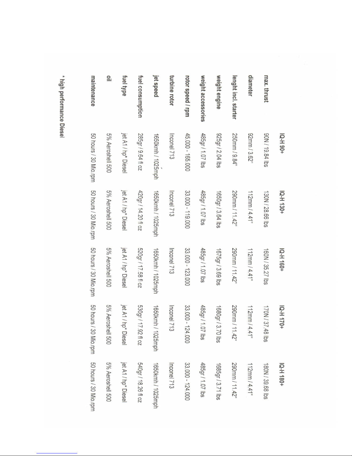
technical specifications IQ-Hammer Series

8
Hammer Engines GmbH / IQ-Series / Instruction Manual
installation plan

9
Hammer Engines GmbH / IQ-Series / Instruction Manual
Checklist for the first time of Operation of the IQ-Hammer turbine
Install and connect the components according to the installation plan (see page
14). Pay special attention to the correct connection of the FUEL valve and to a
proper plumbing of the tubes without kinking them. The arrow on the fuel pump
and the valve indicate the flow direction of the fuel to the engine.
The QS quick connectors (blue) should snap in when you plug in the tube. The
tube can only be released by pressing on the blue ring while pulling the tube out.
Only use approved PUN/ Festo tubes with a diameter of 4 mm (0.16") or 6mm
diameter (0.236”), respectively.
Charge all batteries, paying special attention to the correct charging program for
the lithium manganese battery, i.e. a maximum charging voltage of 12.6 V. Use
the 3s LiPo charging mode of your charger at 1 – 2 Amps.
Check the temperature sensor to the environment temperature via the parameter
Menu → 2-ADJUSTMENTS → 2.3 ADJUST TEMP → AMBIENT TEMP
Teach the remote control: OFF, IDLE, 100 %, via the menu
→ 2 ADJUSTMENTS →
2.1 LEARN RC TIMING → make adjustment

10
Open the fuel tank ventilation, then fill the fuel tank(s) with fuel containing
approximately 5 % of AeroShell 500 or AeroShell 560 oil
Have a CO2 fire extinguisher at hand!
Turn on the R/C transmitter, and then turn on the receiver.
Place your aircraft model with the nose into the wind.
Start the jet engine (keep a safe distance, see page 6!):
1. Throttle down + trim down => remove LOCK
2. Trim up => RUN – cleared
3. Throttle up and down again => AUTOSTART activated, see EDT
display.
Checklist for Turning the Engine Off
Place the aircraft model with the nose against the wind.
Turn the jet engine off: Throttle down + trim down (below 25%) => -OFF
Wait until the automatic cool-down procedure of the engine is finished.
Check the INFO data about the operating states (see page 14 ff).
After finishing the flight activities, remove all fuel from the tank(s) and close
the fuel tank ventilation.

11
Hammer Engines GmbH / IQ-Serie / Instruction Manual
ECU und IO-circuitry
ECU Connector layout
IO-Board
In order to extend the Input/ouput ports as well as the interface you can connect the IO-Board
in between the Electronics and the Terminal and place it at an accessible location inside your
airframe.
Speaker:
• Short tone : On – Terminal connected
• Long tone : Begin Auto start (open throttle)
• Repetitive with a short interval : Voltage alert/Temp.-Sensor defect/burner defect
(Check symbol on display)
Status-LED:
• Green : OFF
• Orange : READY
• Red : Turbine in automatic Mode
Input-button:
While in OFF-Mode you can push fuel by pressing this button
Beeper
pushbutton

12
Hammer Engines GmbH / IQ-Serie / Instruction Manual
Electronic Data Terminal – EDT
Instructions
All parameters relevant to this operation of the turbine will be transmitted to the EDT via the
Terminal where they are being stored. The following will give you an overview of the
complete menu structure.
You input commands by pressing the four buttons UP (), DOWN (), ESC () and Enter
().
You can connect the terminal to a running system in order to check and change parameters on
the fly.
Using the up and down arrows you scroll up and down or increase and decrease values.
Using the –button you can exit the menu without storing any changes made. Any changes
made followed by pressing ESC will NOT be stored.
You store these changes by pressing the -button. For example, should you change the max
RPM from 100.000 to 105.000 followed by pressing ENTER you are in effect storing the new
values.

13
Hammer Engines GmbH / IQ-Serie / Instruction Manual
MENUSTRUCTURE
And flow
Access Sub menus by pressing
Exit the Submenu without storing any changes by pressing

14
Temperature RPMx100 / Throttle-
Channel (%)
Status Pump- or. Battery- Voltage
Hammer Engines GmbH / IQ-Serie / Instruction Manual
Status Readout on EDT
You can browse through the respective status readout screens by pressing the -buttons.
Once switched on the following Screen 1 will be displayed by default:
Temperature : Current operating temperature of the turbine
RPM : Current revolutions per minute x 1.000
Status : Current Status (OFF, READY, AUTOMATIC etc...
(see below)
Pump Voltage : current pump voltage (can be changed to battery voltage)
Display Symbols
• Battery fully charged
§ Battery ok
¶ Battery empty
¢ Burner defect
† Pump running/Pump Voltage
Should an error occur (Battery empty, Burner defect etc) the IO-Board will emit an alarm
tone.

15
Hammer Engines GmbH / IQ-Serie / Instruction Manual
Status readouts / the order of readouts on this page corresponds to the
order they occur in during the startup sequence
OFF
Turbine off, waiting for Standby
STANDBY
Standby – waiting for Startup Sequence. (Throttle stick and throttle trim at 0%, then both
opened up to 100%)
PRE Heat
The turbine is pre-heating
BURNER ON
The burner is on
FUELIGNIT
Fuel is being ignited
BURN OUT
Excessive fuel is being burned off
RAMP UP / F-Pulse
Turbine revs up to idle
STEADY
Waiting for stabilization of turbine RPMs
CAL IDLE
Idle is being adjusted
CALIBRATE
Calibration rpm is being adjusted
WAIT ACC
Waiting for end of ramp up
STEADY
Waiting for stabilization of turbine RPMs
GO IDLE
Calibration of idle rpm
AUTO 4,7 V
(Value differs depending on the turbine used)
AUTO-HC
Turbine in automatic mode – top rpm have been adjusted – mandatory to enable failsafe in
case of sensor failure

16
Hammer Engines GmbH / IQ-Serie / Instruction Manual
STATUS
AUTO
Turbine in automatic mode
EMERGENCY
Emergency mode – the turbine will be controlled by pump voltage alone
SLOW DOWN
Turbine off – waiting for standstill
COOL DOWN
The turbine is actively being cooled by spooling up
Status Screens
You can flip between Status screens by pressing the - buttons.
Status Screen 2 – FUEL
Status screen 2 displays the current fuel consumption and the remaining
quantity. It is being displayed both as a bar and text readout.
Status Screen 3 – ELECTRICITY
Status screen 3 displays the current status of the battery. It is being displayed
both as a bar and text readout.
Status Screen 4 – MIN/MAX-VALUES
Displays the MIN/MAX-Values of the last turbine run – these values are being
deleted once you switch off the ECU. You can browse between the individual
readouts by pressing
Status Screen 5 – ERROR DISPLAY
Status screen 5 displays the cause for the last shutdown.

17
Hammer Engines GmbH / IQ-Serie / Instruction Manual
Menu and Settings
↓
To enter the max
revolution speed of the turbine
↓
To enter the min
revolution speed of the turbine
↓
This parameter specifies the acceleration/throttle-up time
(more thrust) and deceleration/throttle-downtime (less
thrust) of the engine. Depending on ambient factors such
as temperature, humidity of air density you will need to
adjust these values. A too hard of a throttle setting can
lead to overheating and blow-outs of the turbine.
↓
This parameter specifies the minimum voltage [V] for the
fuel pump at startup
. High voltage may lead to
unnecessary expulsion of flames; low voltage might keep
the turbine from starting up.
↓
This parameter specifies the voltage which the ECU will
calibrate to after startup. The ECU will calibrate the
turbines idle speed automatically; this value is only a
reference to adjust the ramp.

18
Hammer Engines GmbH / IQ-Serie / Instruction Manual
This parameter specifies the maximum allowed voltage
[V] for the fuel pump. Do not confuse this value with
pump-voltage at 100% throttle. This value is only being
used in order to identify failure. Should this limit be
exceeded the pump will be switched of automatically!
The set voltage should be a tad above 100% throttle V.
Please be aware, should the set voltage be too low the
turbine will not reach max revolution speed and the
turbine might go into auto-shutdown
!
↓
This parameter adjusts throttle exponential from 0% to
100%

19
Hammer Engines GmbH / IQ-Serie / Instruction Manual
↓
The ECU must be calibrated to your transmitter. Please
follow these instructions:
1. THRO. LO/TRIM LO: Set throttle and throttle trim
to minimum -> press
2. THRO. LO/TRIM HI: Set throttle trim to max, leave
throttle stock at minimum -> press
3. THRO. HI/TRIM HI: Set throttle stick to max, leave
trim at max -> press
Done.
Should there be a auxiliary function present
(ON/OFF or Smoker-Valve) you will have to teach
the auxiliary-function as well. This is being followed
by a plausibility check. Should there be a failure
followed by an alarm tone you will need to correct
the cause for failure and calibrate again. In most
cases the transmitters programming is at fault.
↓
Calibration of the Heat Element
↓
In order to use the fuel flow readout display you will
need to enter throughput at 1 Volt (FUEL-FLOW
@1.0V) and 2 Volt (FUEL-FLOW @2.0V) pump
voltage as well as enter the size of your fuel tank in order
to enable the calculation of the remaining fuel at any
given time.

20
Hammer Engines GmbH / IQ-Serie / Instruction Manual
↓
Input the minimum and maximum battery voltage. This
will determine at what thresholds the unit will read out
Battery Full or Battery Empty.
↓
Choose the language you want the unit to be set to.
↓
Shows the total operating time
↓
Sets up receiver fail-safe mode (see the corresponding
section in this manual)
↓
Should you be running a auxiliary-channel you can input
its function here. Possible choices :
o NO FUNCTION : Auxiliary-Channel not being used
o ON/OFF SWITCH: The Auxiliary-Channel
replaces the throttle trim function
o SMOKER VALVE: A „Smoker Valve“ can be
operated. Please note that this function will only be
active above 300 degrees Celsius.

21
Hammer Engines GmbH / IQ-Serie / Instruction Manual
Activates the Telemetry transmitter (TRX-2400).
Amount of Data packets per time unit (OFF/1x/2x/3x),
channel transmitted on (COM-CHANNEL 0-10) and the
address of the Graphic-Telemetry (0-10000). Please
refer to the corresponding manuals for further
information.
↓
IMPORTANT !
This will reset the ECU to factory settings.
___________________________________________________________________________
↓
Menu point 4 will display stored as well as current GPS and Airspeed-date generated by
the GAS-Module.
Latitude and Longitude:
Displays current Geo-Information in Latitude and Longitude.
UTC-TIME – valid positioning – Heading – Satellites:
UTC (U): The second screen displays the UTC-Time in H-M-S format. Depending on the
time zone you will need to add or subtract accordingly.
Valid positioning (NOK-OK-3D): The top right corner shows whether your current
positioning is valid. As follows: NOK = not OKay, OK. = OKay, but only in 2D and 3D. =
OKay in 3D .
Heading (C): Heading in degrees.
Satellites (SAT): Amount of satellites connected at the moment. The higher the amount the
more precise will the read out GPS positioning will be. As a rule you should be connected to a
minimum of 7 satellites.

22
Hammer Engines GmbH / IQ-Serie / Instruction Manual
GPS-Speed /Altitude
GPS-V: Speed in km/h
GPS-ALT: Current altitude above 0 in meters
Maximum radial distance and speed
G-MAX-R: Maximum recorded distance from point of start-up
G-MAX-V: Maximum recorded Groundspeed (GPS)
Maximum/Minimum Altitude
G-MAX-ALT: Maximum recorded altitude above
G-MIN-ALT: Minimum recorded altitude above 0
AIRSPEED – IAS and MAXIMUM IAS
IAS: Current Airspeed (IAS = Indicated Airspeed)
MAX-IAS: maximum recorded current airspeed
The values of both GPS and Airspeed can differ tremendously – the one measures
groundspeed, the other airspeed!
___________________________________________________________________________
↓
(1) FUELPUMP TEST:
IMPORTANT !!! You can switch the pump on and off in
this menu. Make sure that the turbine cannot be
flooded!!! THIS CAN LEAD TO A FIRE!!! Use the
-arrows to adjust the Fuel pump’s Voltage, use to
switch the pump on and off. This menu is only functional
while the turbine is not running and switched off.
↓
(2) BURNER TEST
Use the -arrows to adjust the burner unit’s voltage.
Use to switch the burner on and off.

23
Hammer Engines GmbH / IQ-Serie / Instruction Manual
↓
(3) This option has been removed due to the use of a
ceramic burner.
↓
(4) FUEL VALVE TEST
Using the fuel valve can be operated manually.
↓
(5) SMOKER-VALVE TEST
Using the smoker valve can be operated manually.
↓
(6) RC-TIMING TEST
The transmitter throttle position is being displayed.
↓
(7) RPM-SENSOR TEST
The RPM signal is being displayed.
↓
(8) TEMPERATURE SENSOR TEST
The temperature sensor is being tested
↓
24
Hammer Engines GmbH / IQ-Serie / Betriebsanleitung
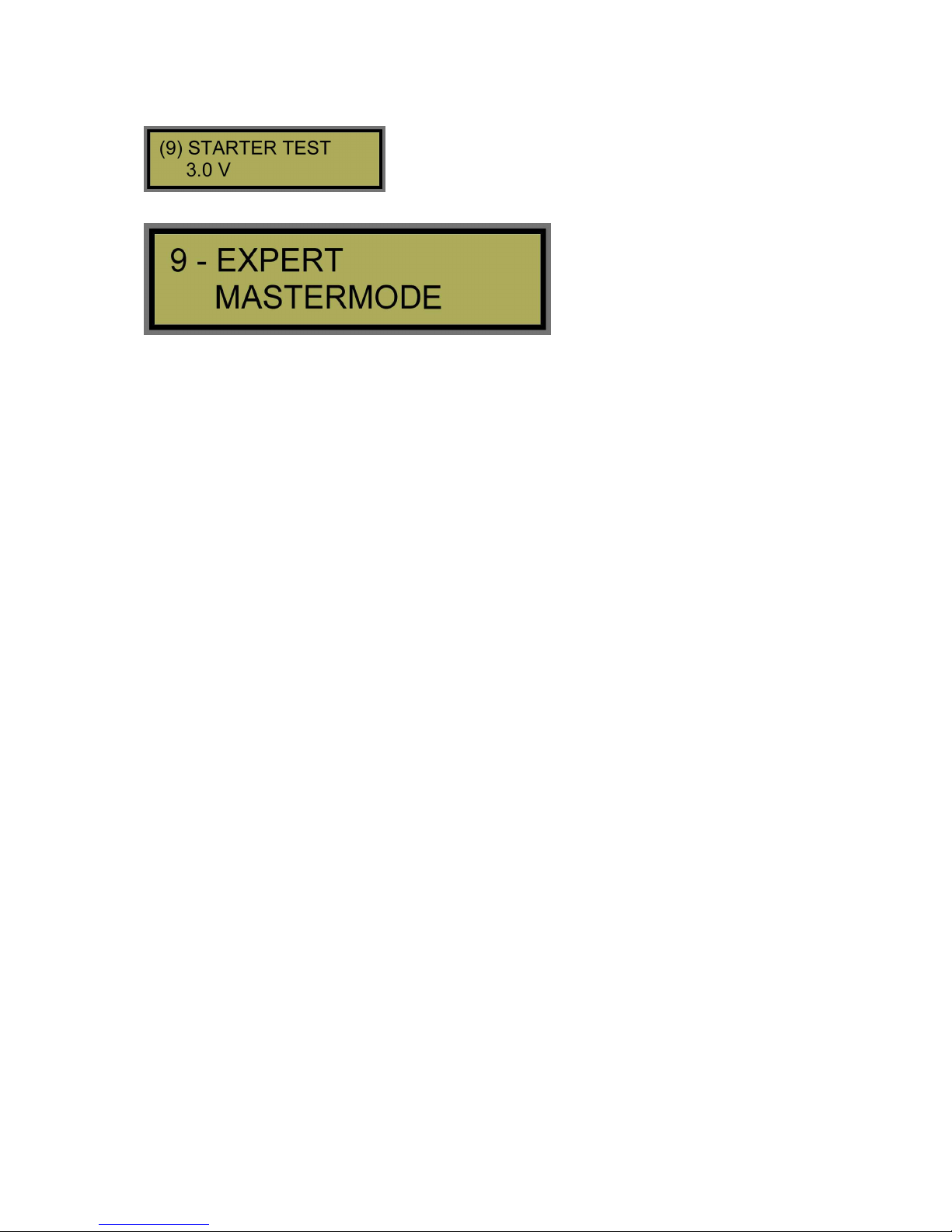
(5) STARTER TEST
Using the starter motor can be operated manually.
___________________________________________________________________________
↓
IMPORTANT! Using this menu you can adjust all vital parameters of your
turbine. These settings are meant for experts only. This menu is disabled by
default!
Auto-Calibration procedure
1. Ramp up to calibration rpm
2. Stabilization
3. Idle rpm are being adjusted
4. The turbines response curve is being calculated
Course of normal operation
Characteristic features of normal operation:
• Temperature/RPM dependent control of fuel feed
• Monitoring of RPM and temperature limits
• Recording of all relevant data (BLACKBOX)
• Telemetry transmission
Failsafe operation
The ECU comes with a failsafe setting which becomes active should rpm or temperature
sensors fail (Status: EMERGENCY). In this mode the turbine will be controlled by pumpvoltage alone. A pre-occurring one-time stabilization of full throttle is necessary (Status:
AUTO-HC). The cause of error needs to be eliminated before the turbine can be started again.
Safety features
• RPM: exceed – fall below - failure
• Temperature: exceed – fall below - failure
• Power: Minimum voltage
• Output Fuel pump: failure/short circuit
• Input receiver: failure –glitch –Fail Safe

25
Hammer Engines GmbH / IQ-Serie / Instruction Manual
Radio equipment
Throttle
The turbine is operated by the throttle channel:
• Startup initiation
• RPM / thrust control during flight
• Shut down
You have to teach the transmitter before operating the turbine for the first
time or after reset to factory setting!
Turbine startup:
1. Throttle trim and throttle stick to minimum
2. Throttle trim and throttle stick to maximum - STANDBY
3. Throttle stock to minimum
4. Throttle stick back to maximum within a 3 second window -> STARTUP
RPM/Thrust control
Once the turbine has successfully started and finished the calibration process the turbine can
be controlled by the throttle stick.
Shutdown
Throttle stick and trim to minimum, this will initiate the shutdown sequence.
Transmitters with digital trim
We recommend mixing a switch in with your throttle channel to enable a quick „minimum
throttle trim “sequence.
FAIL SAFE / Receiver glitch
The ECU continuously monitors whether the throttle signal is valid and within limits. When
you teach the transmitter you are setting upper and lower limits. Should there be a command
below or above set limits the system will go to failsafe. Status display 1 will read „ –FAIL“
instead of a valid throttle readout in %.
FAIL SAFE Settings in Menu 3.4
FAILSAFE DELAY:
Delay between first occurrence of glitch or bad command and initiation of failsafe thrust
(Menu point FAILSAFE THRUST).

26
Hammer Engines GmbH / IQ-Serie / Instruction Manual
FAILSAFE TIMEOUT:
Time between initiation of failsafe trust and complete shutdown, should the glitch or bad
command continue.
FAILSAFE THRUST:
Once the FAILSAFE DELAY has passed the turbine will go to this preset rpm.
Deactivation of the FAIL SAFE Function:
Should you set the value for FAILSAFE DELAY to 0.0 sec, Fail Safe Thrust will be
deactivated.
PCM Transmitter/Receiver FAIL SAFE Settings:
In order to recognize a Fail Safe using PCM radio equipment the radio will have to emit
signals in case of a failsafe that are outside the learned limits. Hence, should you have taught
100% positive and 100% negative travel, then failsafe has to be set to negative 110% and
positive 110%. Please see your radios manual.
Auxiliary channel
Functions as an on/off switch:
ON/OFF Switch (Replaces trim):
The auxiliary channel replaces trim, switch ON = trim up / switch OFF = trim down. Please
note that trim needs to be set to maximum should you want to use this switch function!
Smoker-Valve:
A connected smoker can be operated. This channel will be activated above 300 degrees
Celsius.
Connect the ECU to the receiver using a 1:1 servo cable (PATCHCABEL) on AUX.
RECEIVER

27
Hammer Engines GmbH / IQ-Serie / Instruction Manual
Specifications
• Powerful RISC Microcontroller
• Simple programming using FLASH MEMORY
• Modern USB PC-connection
• Kero start
• Can be operated on a single channel
• Turbine startup using GSU for models with multiple engines
• Integrated Data Logger: The data collected during the 30 minutes before the last
shutdown is being stored at 5 snapshots per second
• Telemetry: Data can be transmitted from the telemetry transmitter on board the
airplane to the ground terminal (Laptop)
•
Failsafe mode: Turbine operates even in case of sensor failure
•
Output stages with current sensors (Fuel pump – Starter – ceramic burner)
ACCESSORIES
IQ-TRX-2400: 2.4 GHz Telemetry transmitter
Telemetry transmitter on 2.4 GHz
IQ-JET: 2.4 GHz Telemetry-Graphic terminal
Graphic terminal with data output (communicates with a PC or Laptop), real-time display of
all important data

28
Hammer Engines GmbH / IQ-Serie / Instruction Manual
Notes:

29
Hammer Engines GmbH / IQ-Serie / Instruction Manual
Possible Error messages
Errors messages during startup:
RPM < 2.000 DURING WARMUP/ VORHEIZEN
REASON: Turbine RPM dropped below 2.000 during warm-up
CAUSE: Starter voltage is too low during warm-up (Menu 9.16), starter failure, turbine
stuck
RPM < 5.000 DURING RAMPUP
REASON: Turbine RPM dropped below 5.000 during ramp up
CAUSE: Starter voltage is too low during ramp up, starter failure, turbine stuck
FLAMEOUT DURING WARMUP/ VORHEIZEN
REASON: Temperature dropped below 200°C during warm-up.
CAUSE: Starter voltage too high (Menu 9.16), Fuel rate set too low (Menu 1.8)
FLAMEOUT DURING RAMPUP
REASON: Die Temperature dropped below 200°C during ramp up.
CAUSE: Starter voltage too high (Menu 9.19), Fuel feed failure
Errors messages during Auto-Calibration
FLAMEOUT DURING CALIBRATION
REASON: Temperature dropped below 250°C during calibration.
CAUSE: Fuel feed interrupted -> User error
RPM DROPPED BELOW MINIMUM CALIBRATION VALUES
REASON: RPM dropped below values needed for acceleration
CAUSE: RPM sensor being interfered by ambient light, fuel feed failure (bubbles) ->
User error
ERROR DURING CALIBRATION
REASON: It was not possible to stabilize calibration RPMs
CAUSE: Calibration rate set too high (Menu 9.4), fuel feed failure -> User error
CALIBRATION VOLTAGE EXCEEDED
REASON: The max set Voltage has been exceeded
CAUSE: The max set Voltage has been set too low (Menu 9.5), fuel feed failure,
fuelpump failure -> User error

30
Hammer Engines GmbH / IQ-Serie / Instruction Manual
CALCULATED MAX PUMP VOLTAGE TOO HIGH
REASON: Pump voltage needed for full throttle operation exceeds preset limit (Menu 1.6)
CAUSE: The max pump voltage has been set too low, the corrective factor has been set
too high (Menu 9.6), pump voltage at calibration RPMS is too high (Points towards a fuel
feed or turbine problem) -> User error
ERROR MESSAGE DURING OPERATION
THROTTLE CHANNEL FAILURE
REASON: During operation the throttle channel seized
CAUSE: PPM transmitter glitch
RPM SENSOR FAILURE
REASON: RPM sensor failure
CAUSE: Ambient light interferes
MAX RPM EXCEEDED
REASON: The set max RPM has been exceeded
CAUSE: Set wrong by user / Ambient light interferes with RPM sensor -> User error
MIN RPM UNDER-RUN
REASON: The set min RPM has been under-run
CAUSE: Set wrong by user / Ambient light interferes with RPM sensor, fuel feed
problem -> User error
MAX. TEMP EXCEEDED
REASON: The max temp of 800°C has been exceeded
CAUSE: The main cause of overheating is mechanical failure -> User error
FLAMEOUT DURING OPERATION
REASON: Temperature has dropped below 250°C.
CAUSE: Throttle curve to steep/fast, bubble in fuel feed, fuel tank empty -> User error
FAIL SAFE
REASON: The receivers failsafe duration exceed limits set in Men Fail Safe Timeout (3.4)
when in Failsafe Modus
CAUSE: Receiver glitch/ malfunction

31
Hammer Engines GmbH / IQ-Serie / Instruction Manual
GENERAL ERROR MESSAGES
PUMPDRIVER FAILURE
REASON: The max allowed pump load (Menu 1.6) has been exceeded
CAUSE: Pump blocked by contamination; pump disconnected -> User error
BATTERY VOLTAGE to low
REASON: Turbine battery voltage dropped below limit set in Menu 3.1
CAUSE: Battery empty or defective -> User error

32
PURCHASE AGREEMENT, FULL ASSUMPTION OF LIABILITY AND
INDEMNITY AGREEMENT
Buyer purchases from Hammer Engines GmbH, a Limited Liability Company or from one of
Hammer Engines GmbH authorized dealers, a MINIATURE TURBOJET ENGINE for model
aircraft, cars or boats ("Model Engine") for the invoice price, accompanying this sale, and
Buyer and Vogelsang Aeroscale agree to all of the following terms and conditions:
1. Buyer's Representations. Buyer represents that he/she is very experienced in model
airplane operation, and that all of the information set forth in the Purchase Application is true
and correct. Hammer Engines GmbH relies on such representations, and would not enter into
this sale but for these representations.
2. Buyer's Acknowledgment of Risks and Dangers. Buyer recognizes that operation of the
Model Engine may be dangerous, and that under certain circumstances, its handling will be
dangerous. As set forth in Paragraph 3 below, Buyer accepts full responsibility for all of these
risks and waives all liability as against Hammer Engines GmbH.
(a) Buyer's Acknowledgment of Danger. Buyer expressly acknowledges that use of the
Model Engine is dangerous if improperly handled, and could inflict injury if attempts are
made to handle it properly, if the user does not fully acquaint himself/herself with the Model
Engine's operation procedures. The Model Engine may cause burns to the user, or the user's
assistant, particularly in the start-up procedure, and Buyer agrees to use extreme caution. The
Model Engine exhaust is extremely hot, and will burn someone or something placed directly
behind the exhaust tube. Highly flammable liquid is used to operate the Model Engine and it
or its fumes will ignite easily and flare up rapidly. The Model Engine itself remains extremely
hot, after it is shut off, and requires a cooling down period. Improper use of the Model Engine
or failure to follow Academy of Model Aeronautics ("AMA") guidelines and rules will result
in injury to the user, the user's assistant, or bystanders. Operation of the Model Engine in any
location other than an approved location, and under safe circumstances could lead to injury to
bystanders. A risk exists from explosion, in the event of tampering, modifications leading to
over-speed or extreme metal fatigue.
(b) Buyer's Obligation to Become Fully Acquainted With Operation Procedure. Buyer
acknowledges receipt of operating instructions for the Model Engine which depicts its
handling and operation. Buyer agrees to thoroughly acquaint himself/herself with these
materials, and to require his/her assistant to become equally familiar with them. Buyer
expressly agrees not to allow any person to assist in the start-up procedure of the Model
Engine, who has not become thoroughly familiar with these materials.
(c) Agreement to Use Qualified Assistant in Start-Up Procedure. Buyer acknowledges that
the start-up procedure for the Model Engine cannot be safely done, without an assistant.
Buyer expressly agrees to use an assistant, who is thoroughly familiar with the Model Engine
and its operation as set forth above, on each occasion when the Model Engine is started up.
(d) Warning to Bystanders. Buyer acknowledges that injury or burns to bystanders could
occur, during the start-up procedure or when operating the Model Engine. Buyer expressly
agrees to take all steps necessary to assure that no bystander will be in a position to receive
injuries during the start-up procedure, or while the Model Engine is running.
Hammer Engines GmbH / IQ-Series / Manual

33
3. Full Assumption of Liability; Waiver and Release of Hammer Engines GmbH f. Buyer
assumes all risk of injury, harm and damage, of every nature whatsoever, to himself/herself
and his/her property. Buyer fully and completely waives and releases any and all claims which
he/she might have at any time arising out of the purchase, handling, or operation of the Model
Engine. This assumption, waiver and release is complete, full, and comprehensive.
Hammer Engines cannot supervise the adherence to the assembly and operating instructions
for the aircraft model and the jet engine, nor the installation, operation, use and maintenance
of the model aircraft components. Therefore, Hammer Engines does not assume any liability
for losses, damage or costs caused by the proper or improper operation and proper or
improper behavior use of the IQ-Hammer engines or the jet model airplane. By operating the
jet engine, you confirm to be aware of the fact that Hammer Engines cannot supervise or
control the compliance with the instructions in this manual regarding assembly, operation and
use of the aircraft model, jet engine and remote control unit. On Hammer Engines’ part, no
promises, contractual agreements, guarantees or other agreements with persons or companies
regarding the safety, functionality and operation of the model and the jet engine have been
made. When buying this aircraft model or jet engine, you as the operator were relying on your
own expertise and judgment.
(a) Release Even If Hammer Engines GmbH Is Negligent. The waiver and release
contained herein releases Hammer Engines GmbH from all conduct, no matter how it could be
characterized or alleged. Hammer Engines GmbH shall not be liable for its own negligence,
whether active, passive, primary, or secondary. Hammer Engines GmbH shall not be liable for
its sole negligence. Hammer Engines GmbH shall not be liable for its willful misconduct. s
Hammer Engines GmbH hall not be liable based on any theory in strict liability in tort.
Hammer Engines GmbH shall not be liable for any alleged breach of warranty, whether
express or implied, of any nature whatsoever, whether a warranty of fitness for a particular
use, merchantability, or otherwise. There is no warranty of merchantability; there is no
warranty of fitness for a particular purpose; and there are no warranties which extend beyond
the description on the face hereof or Hammer Engines GmbH Two Year Limited Warranty.
(b) Waiver Effective for All Time. The waiver and release contained herein is effective,
without regard to the passage of time. It is effective indefinitely. It will not be changed by any
modification to the Model Engine, to any later sale, or other changes in circumstances.
(c) Release Extends to Hammer Engines GmbH and All Its Associates. The waiver and
release contained herein protects Vogelsang Aeroscale and all of its employees, officers,
principals, owners, designers, and agents ("Associates").
4. No Modifications to Model Engine. Buyer agrees to make no modifications of any kind to
the Model Engine. This Agreement pertains to the entire life of the Model Engine.
5. Two year limited warranty
The warranty covers the free repair or replacement of parts that exhibit proven defects of
fabrication or material defects within the warranty period from the date of purchase. Any
further claims are excluded. Costs for packaging and shipping are paid by the buyer. No
liability is assumed for loss during transport. When sending the defective article to Hammer
Engines, a detailed description of the fault and the invoice stating the date of purchase must be
included. The warranty is void if the defect of the part or the model is caused by an accident,
improper handling or improper use. Removing or damaging the safety seal on the cover of the
jet engine voids the warranty.
Hammer Engines GmbH, a Limited Liability Company, (“IQ-Hammer”) warrants that this
MINIATURE TURBOJET ENGINE for model aircraft, cars or boats (“Model Engine”)
enclosed with this warranty statement is free from defects in materials and workmanship
during normal usage, according to the following terms and conditions.

34
1) The limited warranty extends to the original purchaser ("Buyer") of the Model Engine
and is assignable or transferable to any subsequent purchaser / end-user.
2) Upon request from Hammer Engines GmbH, the Buyer must prove the date of the
original purchase of the Model Engine by a dated bill of sale or dated itemized receipt.
3) Warranty coverage begins the day you buy the Model Engine. For 2 (two) years all
labor and parts except for the ceramic burner and battery will be repaired or replaced free of
charge should there be proven defects of fabrication or material defects. All parts, including
repaired and replaced parts are covered for the original warranty period. When the warranty
on the Model Engine expires, the warranty on all replaced and repaired parts also expires.
4) During the limited warranty period, Hammer Engines GmbH will repair or replace, at
Hammer Engines GmbH option, any defective parts with new or factory rebuilt replacement
items if such repair or replacement is needed because of Model Engine malfunction or failure
during normal usage. No charge will be made to the Buyer for any such parts. Hammer
Engines GmbH will also pay for the labor charges incurred by Hammer Engines GmbH in
repairing or replacing the defective parts. The limited warranty does not cover defects in
appearance. Hammer Engines GmbH shall not be liable for any other losses or damages.
5) Any further claims are excluded. Costs for packaging and shipping are paid by the
buyer. No liability is assumed for loss during transport.
6) The Buyer must operate and maintain the Model Engines in accordance to the Model
Engine manual. The Model Engine must be returned to Vogelsang Aeroscale for maintenance
on or before the TBO (Time Before Overhaul) interval of every 50 hours. If Buyer fails to
return the Model Engine within the TBO interval, any damaged parts affected by this
negligence will be subject to additional repair costs.
7) The Buyer shall have no coverage or benefits under this limited warranty if any of the
following conditions are applicable
a) The Model Engine has been subject to abnormal use, abnormal conditions,
improper storage, unauthorized modifications, unauthorized repair, misuse,
neglect, abuse, accident, alteration, improper installation or other acts which
are not the fault of Vogelsang Aeroscale, including damage caused by
shipping.
b) The Model Engine has been damaged from external causes such as crash
damage, foreign object damage, weather, Act of God, improper electrical
connections, or connections to other products not recommend for
interconnection by Vogelsang Aeroscale.
c) The Model Engine is operated for commercial or institutional use.
d) The Model Engine serial number has been deliberately removed, defaced or
altered.
8) If a problem develops during the limited warranty period, the Buyer shall take the
following step-by-step procedure:
a) The Buyer shall ship the Model Engine prepaid and insured to Hammer
Engines GmbH.
b) The Buyer shall include a return address, daytime phone number and / or
FAX number, complete description of the problem and proof of purchase.
c) The Buyer will be billed for any parts or labor charges not covered by this
limited warranty.

35
d) If the Model Engine is returned to Hammer Engines GmbH during the
limited warranty period, but the problem with the Model Engine is not covered
under the terms and conditions of this limited warranty, the Buyer will be
notified and given an estimate of the charges the Buyer must pay to have the
Model Engine repaired, with all shipping charges billed to the Buyer. If the
estimate is refused, the Model Engine will be returned freight collect. If the
Model Engine is returned to Hammer Engines GmbH after the expiration of the
limited warranty period, Hammer Engines GmbH normal service policies shall
apply and the Buyer will be responsible for all shipping charges.
9) The Buyer must bear the cost of shipping the Model Engine to Hammer Engines
GmbH in 91239 Henfenfeld / Germany and bear the cost of shipping the Model Engine back
to the Buyer.
10) The Model Engine consists of newly assembled equipment that may contain used
components that have been reprocessed to allow machine compliance with Model Engine
performance and reliability specifications.
11) Hammer Engines GmbH shall not be liable for delay in rendering service under the
limited warranty, or loss of use during the period that the Model Engine is being repaired.
12) Hammer Engines GmbH neither assumes nor authorizes any other person or entity
to assume for it any other obligation or liability beyond that is expressly provided for in this
limited warranty.
13) This is the entire warranty between Hammer Engines GmbH and the Buyer, and
supersedes all prior and contemporaneous agreements or understandings, oral or written, and
all communications relating to the Model Engine, and no representation, promise or condition
not contained herein shall modify these terms.
14) Buyer must fully accept all conditions of the PURCHASE AGREEMENT, FULL
ASSUMPTION OF LIABILITY AND INDEMNITY AGREEMENT
15) If the Buyer is not prepared to fully accept the liability associated with the use of
this Model Engine, the Buyer is advised to return this Model Engine immediately in new and
unused condition to the place of purchase.
16) This limited warranty allocates the risk of failure of the Model Engine between the
Buyer and Hammer Engines GmbH or one of its dealers. The allocation is recognized by the
Buyer and is reflected in the purchase price of the Model Engine.
17) Questions concerning the warranty may be directed to:
Hammer Engines GmbH
Ottensooser Str.50c
91239 Henfenfeld
Germany
+49 9151 2841
turbodiddi@iq-hammer.com
http://www.iq-hammer.com
 Loading...