

Page 1

User Manual
Translation
Saw-Spindle Moulder
B3 / B3 e-classic
Keep this manual handy and in good condition for continual reference!
Dok.ID: 503010-903_02 • Englisch • 2017-09-15
Page 2

Saw-Spindle Moulder
B3 / B3 e-classic
Note: Year of construction
The machine number of this machine will be printed on this operating manual
The final two digits of the machine number show the year of construction of this machine
e.g. XXX.XX.XXX.17 -> Year of manufacture 2017
Attention!
The machine must be inspected immediately upon arrival. If the machine has been damaged during
transport, or if any parts are missing, a written record of the problems must be submitted to the forwarding
agent and a damage report compiled. Also be sure to notify your supplier immediately.
For the safety of all personnel, it is necessary to conscientiously study this manual before assembly and
operation. This manual must be kept in good condition, and should be considered as part of the machine.
Furthermore, the manual must be kept to hand and within the vicinity of the machine so that it is
accessible to operators when using, maintaining or repairing the machine.
Important Notices!
Please note, that depending on the model of the machine, not all described functions are present, or additional functions and buttons are available (e.g. machines with special functions).
Hammer
A product of the FELDER GROUP!
© FELDER KG
KR-FELDER-STR.1
A-6060 Hall in Tirol
Tel.: +43 (0) 5223 / 45 0 90
Fax.: +43 (0) 5223 / 45 0 99
E-Mail: info@hammer.at
Internet: www.hammer.at
2
Page 3

Saw-Spindle Moulder
B3 / B3 e-classic
Table of Contents
1 General .......................................................................................................................7
1.1 Legend .........................................................................................................................7
1.2 Information about the manual ..........................................................................................7
1.3 Liability and warranty .....................................................................................................8
1.4 Copyright ......................................................................................................................8
1.5 Warranty notice .............................................................................................................8
1.6 Spare parts ...................................................................................................................8
1.7 Disposal ........................................................................................................................9
2 Safety .......................................................................................................................10
2.1 Intended use ................................................................................................................10
2.2 Manual contents ..........................................................................................................10
2.3 Making changes and modifications to the machine...........................................................10
2.4 Responsibilities of the owner operator .............................................................................11
2.5 What is required of personnel ........................................................................................11
2.6 Work safety ................................................................................................................11
2.7 Personal safety .............................................................................................................12
2.8 Hazards arising from the machine ..................................................................................12
2.9 Other risks ..................................................................................................................13
3 Declaration of Conformity ..........................................................................................14
Table of Contents
4 Specifications ............................................................................................................15
4.1 Dimensions and weight .................................................................................................15
4.1.1 B3 basic/B3 e-classic ...............................................................................................................15
4.1.2 B3 winner (comfort) ..................................................................................................................16
4.1.3 B3 Perform ..............................................................................................................................17
4.2 Operation and storage conditions ..................................................................................18
4.3 Electrical connection .....................................................................................................18
4.4 Drive motor .................................................................................................................18
4.5 Particle emission ..........................................................................................................19
4.6 Noise emission ............................................................................................................19
4.7 Tools ..........................................................................................................................20
4.7.1 Saw unit ..................................................................................................................................20
4.7.2 Spindle moulder unit .................................................................................................................21
4.8 Chip extraction ............................................................................................................21
5 Setting up the machine ..............................................................................................22
5.1 Overview ....................................................................................................................22
5.2 Accessories .................................................................................................................23
5.3 Data plate ...................................................................................................................27
5.4 Safety devices .............................................................................................................27
5.4.1 Safety break switches ................................................................................................................27
5.4.2 Spindle moulder guard attachment .............................................................................................28
5.4.3 Circular saw guard ...................................................................................................................28
5.5 Operation and display elements.....................................................................................29
6 Transport, packaging and storage ..............................................................................30
6.1 Safety instructions ........................................................................................................30
6.2 Transport methods ........................................................................................................30
6.2.1 Transport with a pallet jack ........................................................................................................31
6.2.2 Transport with a rolling carriage .................................................................................................31
6.3 Transport inspection ......................................................................................................32
6.4 Packaging ...................................................................................................................32
6.5 Storage .......................................................................................................................32
3
Page 4

Saw-Spindle Moulder
B3 / B3 e-classic
Table of Contents
7 Setup and installation ................................................................................................33
7.1 Safety instructions ........................................................................................................33
7.2 Installation ...................................................................................................................33
7.3 Positioning and levelling the machine ..............................................................................34
7.4 Assembly ....................................................................................................................35
7.4.1 Sliding table ............................................................................................................................35
7.4.2 Assembling/disassembling the outrigger table..............................................................................35
7.4.3 Spindle moulder fence ..............................................................................................................35
7.4.4 Circular saw guard ...................................................................................................................36
7.5 Chip extraction ............................................................................................................36
7.6 Electrical connection .....................................................................................................37
8 Making adjustments and preparations Saw unit ..........................................................38
8.1 Safety instructions ........................................................................................................38
8.2 Sliding table catch .......................................................................................................38
8.3 Crosscut fence on the sliding table .................................................................................39
8.4 Crosscut fence on the outrigger ......................................................................................39
8.5 Cross stop ...................................................................................................................40
8.6 Crosscut fence-extension ...............................................................................................41
8.7 Parallel cutting fence .....................................................................................................41
8.7.1 Sliding ....................................................................................................................................41
8.7.2 Fine adjustment ........................................................................................................................42
8.7.3 Modifying the guide ................................................................................................................43
8.7.4 Removal ..................................................................................................................................43
8.7.5 Swinging out............................................................................................................................44
8.8 Setting the height/angle of cut .......................................................................................44
8.9 Tool change ................................................................................................................45
8.9.1 Preparing to change tooling .......................................................................................................45
8.9.2 Preparing the machine to operate ...............................................................................................45
8.10 Changing the saw blade .............................................................................................46
8.10.1 Loosening/adjusting the splitter ................................................................................................47
8.10.2 Fitting in/changing the splitter ..................................................................................................47
8.10.3 Removing the splitter ...............................................................................................................48
8.10.4 Circular saw guard .................................................................................................................48
8.11 Grooving tools ...........................................................................................................49
8.11.1 Retooling to an operation with grooving tools .............................................................................49
8.11.2 Chucking the grooving tools .....................................................................................................50
8.11.3 Unchucking the grooving tools – Retool to a saw blade operation .................................................51
8.12 Scoring blade ............................................................................................................52
8.12.1 Assembling the scoring blade ..................................................................................................52
8.12.2 Adjusting the scoring unit ........................................................................................................53
8.12.3 Adjusting the width .................................................................................................................53
9 Making adjustments and preparations Spindle moulder unit ........................................54
9.1 Safety instructions ........................................................................................................54
9.2 Sliding table lock .........................................................................................................54
9.3 Adjusting the moulding height/moulding angle ................................................................55
9.4 Spindle moulder fence ..................................................................................................56
9.4.1 Spindle moulder fence „220“ (Standard) .....................................................................................56
9.4.2 Multi-adjustment system for the moulder fence (Option) ..................................................................56
9.4.3 Spindle moulder guard attachment .............................................................................................57
9.4.4 Safety bar guides .....................................................................................................................58
9.5 Power feeder ...............................................................................................................58
9.6 Spindle shaft quick change system (Option - Only possible as initial equipment) ...................59
9.7 Change the tool ...........................................................................................................60
9.7.1 Prepare to change tooling .........................................................................................................60
4
Page 5

Saw-Spindle Moulder
B3 / B3 e-classic
9.7.2 Mounting/removing/changing the spindle moulder tool ................................................................61
9.7.3 Prepare the machine to operate ..................................................................................................62
9.8 Establishing/setting the speed/Set .................................................................................63
9.8.1 Establishing/setting the speed ....................................................................................................63
9.8.2 Maximum spindle resiliance (rotation limit) ...................................................................................64
9.8.3 Adjusting the moulder spindle rotation .........................................................................................65
9.8.4 Sink the spindle moulder ...........................................................................................................66
10 Operation Saw unit .................................................................................................67
10.1 Safety instructions ......................................................................................................67
10.2 Switching on the machine / Switching off the machine / Emergency-stop ..........................68
10.3 Moving the sliding table ..............................................................................................69
10.4 Working techniques ....................................................................................................69
10.4.1 Work stations .........................................................................................................................69
10.5 Working techniques ....................................................................................................70
10.5.1 Permitted working techniques ...................................................................................................70
10.5.2 Prohibited working techniques ..................................................................................................70
10.5.3 General procedures for authorised working techniques ................................................................70
10.5.4 Longitudinal cut ......................................................................................................................71
10.5.5 Trimming ...............................................................................................................................71
10.5.6 Cutting wedges ......................................................................................................................72
10.5.7 Cutting with an outrigger .........................................................................................................73
10.5.8 Cutting with the crosscut fence .................................................................................................73
10.5.9 Groove cuts ...........................................................................................................................74
10.5.10 Working with grooving tools ..................................................................................................75
11 Operation - Spindle moulder unit .............................................................................76
11.1 Safety instructions ......................................................................................................76
11.2 Switching on the machine / Switching off the machine / Emergency-stop ..........................77
11.3 Working techniques ....................................................................................................78
11.3.1 Work stations .........................................................................................................................78
11.3.2 Authorised working techniques .................................................................................................78
11.3.3 Prohibited working techniques ..................................................................................................78
11.3.4 General procedures for authorised working techniques ................................................................79
11.3.5 Moulding long sides and profiles ..............................................................................................79
11.3.6 Slot and tenon moulding .........................................................................................................80
11.3.7 Insert moulding ......................................................................................................................80
11.3.8 Curve moulding .....................................................................................................................81
11.3.9 Moulding with a power feeder .................................................................................................82
11.3.10 Moulding with a high velocity spindle .....................................................................................82
12 Maintenance ...........................................................................................................83
12.1 Safety instructions ......................................................................................................83
12.2 Maintenance schedule ................................................................................................83
12.3 Cleaning the bearing tracks .........................................................................................84
12.4 Lubricating the height and tilting spindles ......................................................................84
12.5 Tightening/replacing the drive belt ...............................................................................85
12.5.1 Retensioning the drive belt .......................................................................................................85
12.5.2 Replacing the drive belt ...........................................................................................................85
12.6 Checking the scoring belt ............................................................................................86
12.7 Cleaning/changing the dust brush of the outrigger arm ..................................................86
12.8 Renewing the sliding table scraper blade (ball cage) ......................................................87
12.9 Disassembling the sliding table ....................................................................................87
12.10 Assembling the sliding table ......................................................................................88
12.11 Lubricating the spindle moulder socket and tilting segments ...........................................89
Table of Contents
5
Page 6

Table of Contents
13 Faults ......................................................................................................................90
13.1 Safety instructions ......................................................................................................90
13.2 What to do if a fault develops .....................................................................................90
13.3 What to do after rectifying the fault ..............................................................................90
13.4 Faults, causes and repairs ...........................................................................................91
13.5 Adjusting the parallel cutting fence guide height .............................................................91
13.6 Adjusting/correcting the parallel cutting fence angle .......................................................92
13.7 Aligning the sliding table ball cage ..............................................................................92
13.8 Adjusting the locking force of the parallel cutting fence ...................................................93
13.9 Professional rip-fence (Option) .....................................................................................93
13.9.1 Adjusting the circular saw fence guide ......................................................................................93
13.9.2 Adjusting the rip fence fine adjustment ......................................................................................94
13.9.3 Adjusting the locking force of the parallel cutting fence ...............................................................94
Saw-Spindle Moulder
B3 / B3 e-classic
6
Page 7
Saw-Spindle Moulder
B3 / B3 e-classic
1 General
1.1 Legend
General
Important technical safety instructions in this manual are
marked with symbols.
These instructions for work safety must be followed. In all
Warning: Risk of injury or death!
This symbol marks instructions that must be followed in order to avoid harm to one‘s health, injuries, permanent impairment or death.
Warning: Danger – electric current!
This symbol warns of potentially dangerous situations related to electric current. Not observing the safety
instructions increases the risk of serious injury or death. Required electrical repairs may only be carried out by
a trained electrical technician.
Attention: Risk of material damage!
!
This symbol marks instructions which, if not observed, may lead to material damage, functional failures and/
or machine breakdown.
Attention:
This symbol marks tips and information which should be observed to ensure efficient and failure-free operation of the machine.
these particular cases, special attention must be paid in
order to avoid accidents, injury to persons or material
damage.
1.2 Information about the manual
This manual describes how to operate the machine
properly and safely. Be sure to follow the safety tips and
instructions stated here as well as any local accident
prevention directives and general safety regulations.
Before beginning any work on the machine, ensure that
the manual, in particular the chapter entitled „Safety“
and the respective safety guidelines, has been read in its
entirety and fully understood. This manual is an integral
part of the machine and must therefore be kept in the
direct vicinity of the machine and accessible at all times.
If the machine is sold, rented, lent or otherwise transferred to another party, the manual must accompany the
machine.
7
Page 8

1.3 Liability and warranty
Saw-Spindle Moulder
B3 / B3 e-classic
General
The contents and instructions in this manual were compiled in consideration of current regulations and stateof-the-art technology as well as based on our know-how
and experience acquired over many years. This manual
must be read carefully before commencing any work on
or with this machine. The manufacturer shall not be liable
for damage and or faults resulting from the disregard of
instructions in the manual. The texts and images do not
necessarily represent the delivery contents. The images
and graphics are not depicted on a 1:1 scale. The actual
1.4 Copyright
This manual should be handled confidentially. It is designated solely for those persons who work on or with the
machine. All descriptions, texts, drawings, photos and
other depictions are protected by copyright and other
commercial laws. Illegal use of the materials is punishable by law.
This manual – in its entirety or parts thereof – may not
be transferred to third parties or copied in any way or
delivery contents are dependent on custom-build specifications, add-on options or recent technical modifications
and may therefore deviate from the descriptions, instructions and images contained in the manual. Should any
questions arise, please contact the manufacturer. We
reserve the right to make technical modifications to the
product in order to further improve user-friendliness and
develop its functionality.
form, and its contents may not be used or otherwise
communicated without the express written consent of the
manufacturer.
Infringement of these rights may lead to a demand for
compensation or other applicable claims. We reserve all
rights in exercising commercial protection laws.
1.5 Warranty notice
The guarantee period is in accordance with national guidelines. Details may be found on our website, www.feldergroup.com
1.6 Spare parts
Attention: Non genuine, counterfeit or faulty spare parts may result in damage, cause malfunction or complete breakdown of the machine.
If unauthorised spare parts are installed in the machine,
all warranty, service, compensation and liability claims
against the manufacturer and their contractors, dealers
and representatives shall be rejected.
Attention: The original spare parts that have been authorised for use are listed in a separate spare parts
catalogue, enclosed in the documentation package supplied with the machine.
Use only genuine spare parts supplied by the manufacturer.
8
Page 9

Saw-Spindle Moulder
B3 / B3 e-classic
1.7 Disposal
General
If the machine is to be disposed of, separate the components into the various materials groups in order to allow
them to be reused or selectively disposed of. The whole
structure is made of steel and can therefore be dismantled without problem. This material is also easy to dispose of and does not pollute the environment or jeopard-
Attention: Used electrical materials, electronic components, lubricants and other auxiliary substances must be
treated as hazardous waste and may only be disposed of by specialised, licensed firms.
ise public health. International environmental regulations
and local disposal laws must always be complied with.
9
Page 10

2 Safety
Saw-Spindle Moulder
B3 / B3 e-classic
Safety
At the time of its development and production, the machine was built in accordance with prevailing technological regulations and therefore conforms to industry safety
standards.
However, hazards may arise should the machine be
operated by untrained personnel, be used improperly or
employed for purposes other than those it was designed
for. The chapter entitled „Safety“ offers an overview of
all the important safety considerations necessary to opti-
2.1 Intended use
The HAMMER B3 saw-spindle moulder is only to be used
to machine wood and other similar machinable materials. Machining materials other than wood is only permitted with the express written consent of the manufacturer.
Attention: Any use outside the machine‘s intended purpose shall be considered improper and is therefore not
permitted. All claims regarding damage resulting from improper use that are made against the manufacturer
and its authorized representatives shall be rejected. The operator shall be solely liable for any damage that
results from improper use of the machine.
mise safety and ensure the safe and trouble-free operation of the machine.
Additionally, in order to further minimise risks, the other
chapters of this manual contain specific safety instructions, all marked with symbols. Besides the various
instructions, there are a number of pictograms, signs and
labels affixed to the machine that must also be heeded.
These must be kept visible and legible and may not be
removed.
Operational safety is guaranteed only when the machine
is used for its intended purposes.
The term „proper use“ also refers to correctly observing
the operating conditions as well as the specifications and
instructions in this manual.
The machine may only be operated with original manufacturer parts and accessories.
2.2 Manual contents
All those appointed to work on or with the machine must
have fully read and understood the manual before commencing any work. This requirement must be met even
if the appointed person is familiar with the operation of
such a machine or a similar one, or has been trained by
the manufacturer.
Knowledge about the contents of this manual is a
prerequisite for protecting personnel from hazards and
avoiding mistakes so that the machine may be operated
in a safe and trouble-free manner. It is recommended that
the operator requests proof from the personnel that the
contents of the manual have been read and understood.
2.3 Making changes and modifications to the machine
In order to minimise risks and to ensure optimal performance, it is strictly prohibited to alter, retrofit or modify the
machine in any way without the express consent of the
manufacturer.
All the pictograms, signs and labels affixed to the
machine must be kept visible, readable and may not be
removed. Pictograms, signs and labels that have become
damaged or unreadable must be replaced promptly.
10
Page 11

Saw-Spindle Moulder
B3 / B3 e-classic
Safety
2.4 Responsibilities of the owner operator
This manual must be kept in the immediate vicinity of
the machine and be accessible at all times to all persons
working on or with the machine. The machine may only
be operated if it is in proper working order and in safe
condition. Every time before the machine is switched
on, it must be inspected for visible defects and general
condition. All instructions in this manual must be strictly
followed without reservation.
Besides the safety advice and instructions stated in this
manual, it is necessary to consider and observe local ac-
2.5 What is required of personnel
Only authorized and trained personnel may work on and
with the machine. Personnel must be briefed about all
functions and potential dangers of the machine. „Specialist staff“ is a term that refers to those who – due to
their professional training, know-how, experience, and
knowledge of relevant regulations – are in a position to
assess delegated tasks and recognise potential risks. If
the personnel lack the necessary knowledge for working on or with the machine, they must first be trained.
Responsibility for working with the machine (installation,
service, maintenance, overhaul) must be clearly defined
and strictly observed. Only those persons who can be
expected to carry out their work reliably may be given
permission to work on or with the machine. Personnel
cident prevention regulations, general safety regulations
as well as current environmental stipulations that apply to
the operational range of the machine.
The operator and designated personnel are responsible
for the trouble-free operation of the machine as well
as for clearly establishing who is in charge of installing, servicing, maintaining and cleaning the machine.
Machines, tools and accessories must be kept out of the
reach of children.
must refrain from working in ways that could harm others, the environment or the machine itself. It is absolutely
forbidden for anyone who is under the influence of
drugs, alcohol or reaction-impairing medication to work
on or with the machine. When appointing personnel to
work on the machine, it is necessary to observe all local
regulations regarding age and professional status. The
user is also responsible for ensuring that unauthorised
persons remain at a safe distance from the machine.
Personnel are obliged to immediately report to the operator any irregularities with the machine that might compromise safety.
2.6 Work safety
Following the safety advice and instructions given in this
manual can prevent bodily injury and material damage while working on and with the machine. Failure to
observe these instructions can lead to bodily injury and
damage to or destruction of the machine. Disregard of
the safety advice and instructions given in this manual as
well as the accident prevention regulations and general
safety regulations applicable to the operative range of
the machine shall release the manufacturer and their
authorised representatives from any liability and from all
compensation claims.
11
Page 12

Safety
2.7 Personal safety
When working on or with the machine, the following
must be strictly observed:
Persons with long hair who are not wearing a hairnet are not permitted to work on or with the machine.
It is prohibited to wear gloves while working on or with the machine.
When working on or with the machine, the following must always be worn by personnel:
Saw-Spindle Moulder
B3 / B3 e-classic
Protective gear (overalls, safety goggles, dust mask, hairnet to contain long hair, etc.)
Sturdy, tight-fitting clothing (tear-resistant, no wide sleeves, no jewellery (rings, bracelets, necklaces, etc.).
Protective footwear
That protects the feet from heavy falling objects and prevents sliding on slippery floors.
Ear protection
To protect against loss of hearing.
2.8 Hazards arising from the machine
The machine has undergone a hazards analysis. The
design and construction of the machine are based on the
results of this analysis and correspond to state-of-the-art
technology.
The machine is considered operationally safe when used
properly.
Nevertheless, there are some residual risks that must be
considered.
The machine runs with high electrical voltage.
Warning! Danger – electric current: Electrical energy can cause serious bodily injury. Damaged insulation
materials or defective individual components can cause a life-threatening electrical shock.
• Before carrying out any maintenance, cleaning and
repair work, switch off the machine and secure it
against being accidentally switched on again.
• When carrying out any work on the electrical equip-
ment, ensure that the voltage supply is completely
isolated.
12
• Do not remove any safety devices or alter them to put
them out of commission.
Page 13

Saw-Spindle Moulder
B3 / B3 e-classic
2.9 Other risks
Warning: Even if the safety measures are followed, there are still certain residual risks that must be considered when working on the machine:
Safety
General safety rules:
• Be wary of sharp edges to avoid cutting yourself, in
particular when changing the tooling.
• Risk of injury due to ejected work pieces and parts of
work pieces (e.g. branches, chips).
• Risk of injury from workpiece kickback.
• Hearing damage as a result of high noise levels.
• Risk of damage to health from dust especially when
working hard woods.
• Risk of injury through being crushed, cut, caught,
wound up or sliced.
depending on the equipment:
• Contact with the rotating saw blade and/or the
scoring unit can cause an injury.
• Danger of injury due to contact with the rotating moul-
der tool.
• Risk of injury from ejected tool pieces (e.g. cutting
pieces).
• Therefore, never stand directly in the cutting line of the
saw blade whilst it is operating (in machining or idling
mode)
13
Page 14

Saw-Spindle Moulder
B3 / B3 e-classic
Declaration of Conformity
3 Declaration of Conformity
EG-Declaration of Conformity
according to Machine Guidelines 2006/42/EG
We hereby declare that the machine indicated below, which corresponds to the design and construction of the model
we placed on the market, conforms with the safety and health requirements as stated by the EC.
Manufacturer: FELDER KG
KR-FELDER-STR.1
A-6060 Hall in Tirol
Product designation: Kreissäge-Fräsmaschine
Make: Hammer
Model designation: B3 basic/winner/perform/e-classic
The following EC guidelines were applied: 2006/42/EG
2006/95/EG
2004/108/EG
The following harmonised norms were applied: EN 940
The prototype test was carried out by: DGUV Test
Prüf- und Zertifizierungsstelle Holz
Fachbereich Holz und Metall
Vollmoellerstraße 11
D-70563 Stuttgart
NB 0392
Conformity with the EC Machine Guidelines certified by: Inspection certificate No. 115008
Saw-Spindle Moulder
This EC Declaration of Conformity is valid only if the CE label has been affixed to the machine.
Modifying or altering the machine without the express written agreement of the manufacturer shall render the warranty null and void.
The signatory of this statement is the appointed agent for
the compilation of the technical information
Johann Felder, Managing Director FELDER KG
Hall in Tirol, 5.3.2015
14
KR-FELDER-STR.1 • A-6060 Hall in Tirol
Page 15
Saw-Spindle Moulder
B3 / B3 e-classic
4 Specifications
4.1 Dimensions and weight
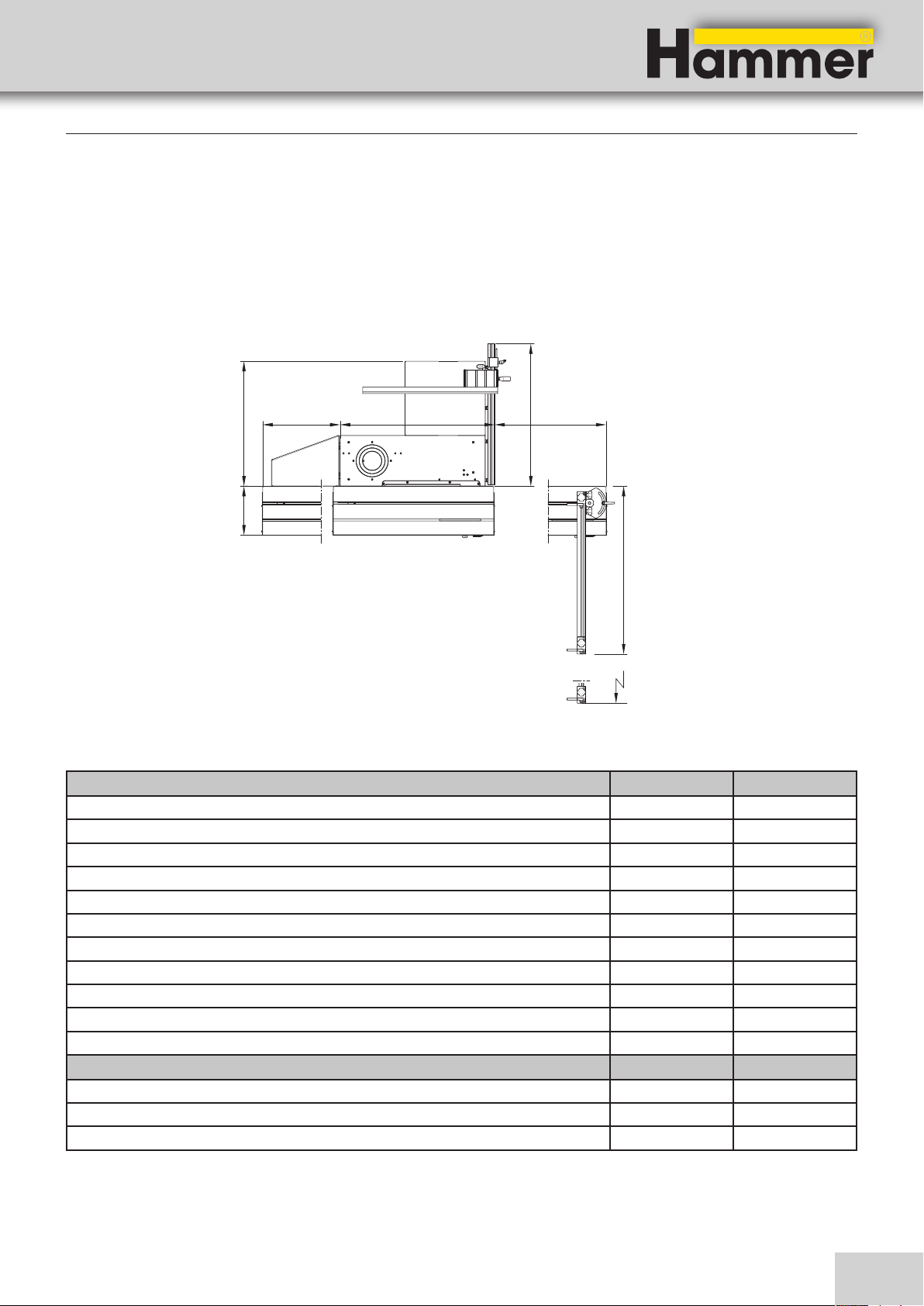
4.1.1 B3 basic/B3 e-classic
Specifications
C1
D
A1 A2B
E
C2
Fig. 4-1: Dimensions B3 basic/e-classic
Machine Standard Option
Sliding table length A
Sliding table travel distance A1
Sliding table travel distance A2
total length A1 + B + A2
Length: Machine table + bar B
Overall width C1
Overall width ( C2
Total height / Working height (approx.) 1555 / 888 mm
Rip capacity D
Width of sliding table E
Net weight *) 240 kg
950 mm 1250 mm
459 mm 764 mm
660 mm 1028 mm
2035 mm 2708 mm
916 mm
844 mm
892 mm 1743 mm
700 mm
290 mm
Machine including packaging
Length x Width **) 1200 x 800 mm
Height 1200 mm
Weight (approx.)* 310 kg
*) with average-sized equipment
**) The transport width measures under 800 mm. This makes it possible to transport the machine through doorways.
15
Page 16
4.1.2 B3 winner (comfort)
A1
Saw-Spindle Moulder
B3 / B3 e-classic
Specifications
C1
D
B
A2
E
C4
C2
C3
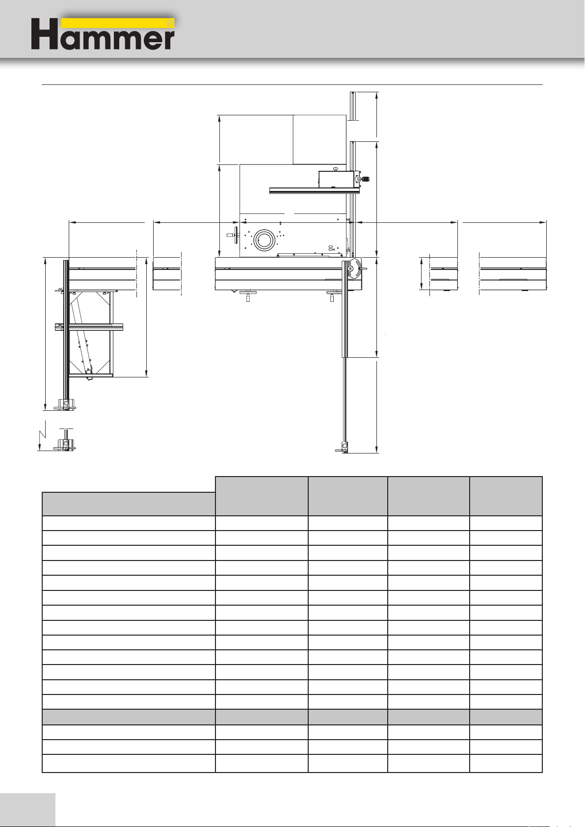
Fig. 4-2: Dimensions B3 Winner (Comfort)
Standard
B3 winner
Machine
Sliding table length A
Sliding table travel distance A1
Sliding table travel distance A2
total length A1 + B + A2
Length: Machine table + bar B
Overall width C1
Overall width C2
Overall width (Option) C3
Overall width C4
Total height / Working height (approx.) 1555 / 888 mm 1555 / 888 mm
Rip capacity D
Width of sliding table E
Net weight *) 330 kg 330 kg
1250 mm 2000 mm 2000 mm -
770 mm 1520 mm 1520 mm -
907 mm 1698 mm 1698 mm 2708 mm 4250 mm 4250 mm 1032 mm 1032 mm
1034 mm 1474 mm 1034 mm 1474 mm
892 (mm 1743 mm - 892 (1743) mm
- 1364 (2140) mm 1364 mm 2140 mm
- 1066 mm 1066 mm
800 mm 1250 mm 800 mm 1250 mm
290 mm 290 mm
Option
B3 winner
Standard
B3 winner
comfort
Machine including packaging
Length x Width **) 1470 x 1160 mm 2100 x 1200 mm
Height 1200 mm 1200 mm
Weight (approx.)* 400 kg 400 kg
Option
B3 winner
comfort
*) with average-sized equipment
16
Page 17
Saw-Spindle Moulder
B3 / B3 e-classic
4.1.3 B3 Perform
Specifications
A1
C3
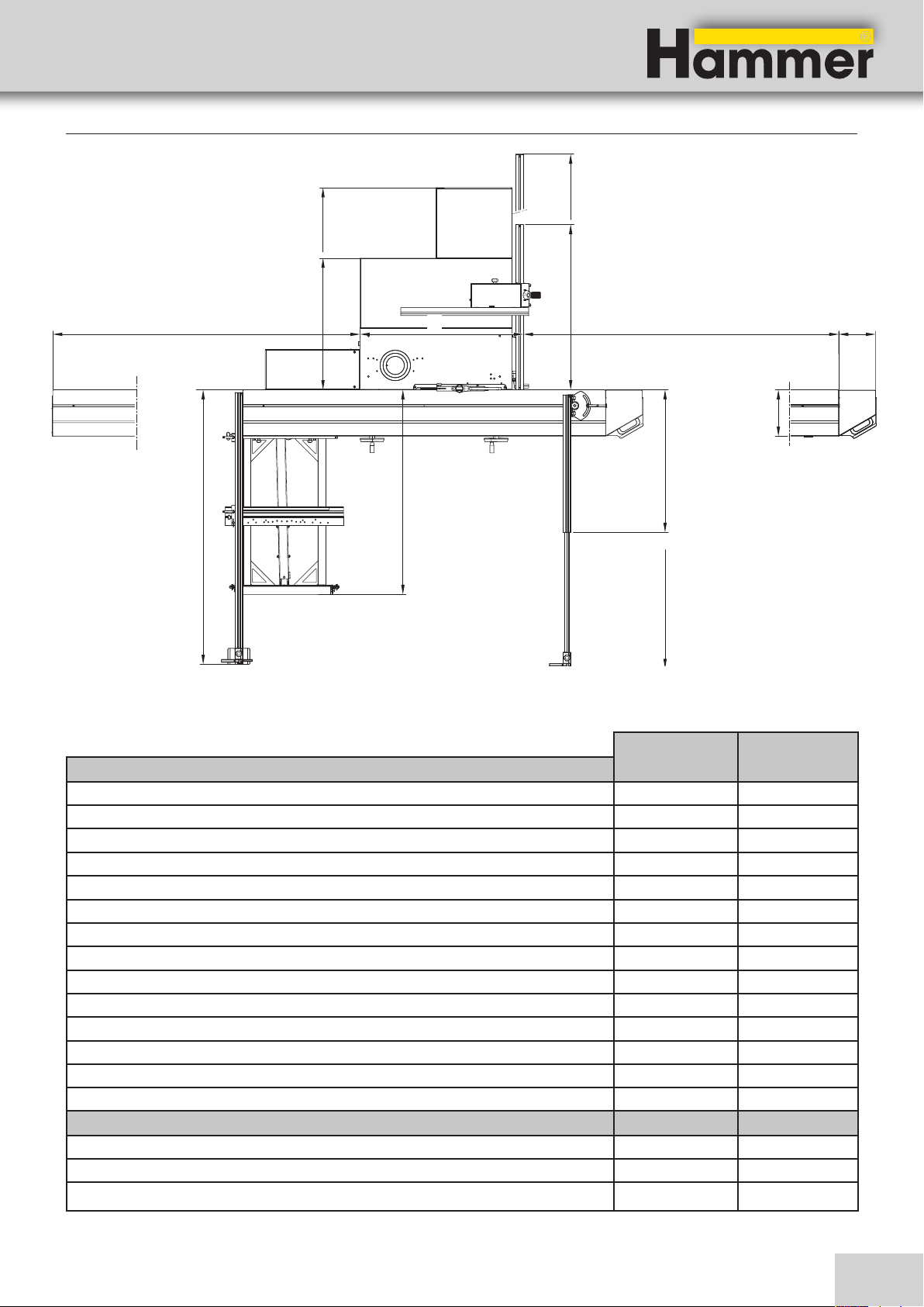
Fig. 4-3: Dimensions B3 Perform
D
B
C1
A2
F
E
C4
C2
Standard
Machine
Sliding table length A
Sliding table travel distance A1
Sliding table travel distance A2
total length A1 + B + A2
Length: Machine table + bar B
Overall width C1
Overall width C2
Overall width C3
Overall width C4
Total height / Working height (approx.) 1555 / 888 mm
Rip capacity D
Width of sliding table E
Wide additional table F
Net weight *) 500 kg
B3 perform
2500mm 1924 mm 1974 mm 4919 mm 1021 mm
1034 mm 1474 mm
892 (mm 1743 mm
1718 (2625) mm
1280 mm
800 mm 1250 mm
290 mm
230 mm
Machine including packaging
Length x Width **) 2300 x 1200 mm
Height 1200 mm
Weight (approx.)* 570 kg
Option
B3 perform
*) with average-sized equipment
17
Page 18

Specifications
4.2 Operation and storage conditions
Operating/room temperature +10° to +40°C
Storage temperature –10° to +50 °C
4.3 Electrical connection
mains voltage according to specification plate ±10%
Safeguarding see circuit plan
Power supply cord (H07RN-F) 3x2,5 mm²/ 5x2,5 mm²
Triggering characteristic C (D*)
*) if starting up is slow, caused by large swinging masses
Saw-Spindle Moulder
B3 / B3 e-classic
4.4 Drive motor
The actual values can be found on the data plate.
Circular saw drive / Spindle moulder unit Alternating-current motor Three-phase current motor
Motor voltage 1x 230 V 3x 230 V / 3x 400 V
motor frequency 50/60 Hz 50/60 Hz
System of protection IP 55 IP 55
B3 Perform
)
Motor power S6-40 %
Motor power S6-40 % - Option*) 3 kW 4 kW
B3 Winner/Winner comfort
Motor power S6-40 %
Motor power S6-40 % - Option*) 3 kW 4 kW (3x 400 V)
B3 e-classic
Motor power S6-40 %
Motor power S6-40 % - Option*) 3 kW -
*
)
*
)
*
- 4 kW
- 3 kW (3x 400 V)
- 3 kW (3x 400 V)
Antriebsmotor Vorritzeinheit (Option)
)
Motor power S6-40 %
*) S6 = operation under load and intermittent service; 40% = relative operating factor
**) Max. cutting height: 2 mm
18
*
0,65 kW
**
)
0,65 kW
Page 19
Saw-Spindle Moulder
B3 / B3 e-classic
4.5 Particle emission
Specifications
The machine was tested for particle emissions according
to DIN 33893. The Wood Authority ascertained, according to the „Principles for Testing Particle Emissions“
(workplace-related particle concentrations) of woodwor-
4.6 Noise emission
The specified values are emission values and therefore
do not represent safe workplace values. Even though a
relationship exists between particle emission and noise
emission levels, an inference cannot be made about
whether additional safety measures need to be implemented. Factors which can significantly affect the emission level that presently exists at the workplace include
duration of the effect, characteristics of the workspace,
Note:
To keep the noise emission as low as possible, always use sharpened tools and operate the machine at the
correct speed.
Ear protection must always be worn; however, such protection cannot be considered a substitute for properly
sharpened tools.
All values in dB(A) and with a measurement uncertainty factor of 4 dB(A).
king machines, that the particle emission values for this
machine are notably below the currently valid atmospheric limit of 2.0 mg/m³. This is certified by the blue label
„BG Wood Particle Tested“.
and other ambient influences. The permissible workplace
values may also differ from country to country. Nevertheless, this information is provided to help the operator better assess hazards and risks. Depending on the location
of the machine and other specific conditions, the actual
noise emission values may deviate significantly from the
specified values.
Saw unit Idle Working
Sound power level
(EN ISO 3746)
Workplace emissions values
(EN ISO 11202)
Spindle moulder unit Idle Working
Sound power level
(EN ISO 3746)
Workplace emissions values
(EN ISO 11202)
99 102
87 90
85 91
76 81
19
Page 20
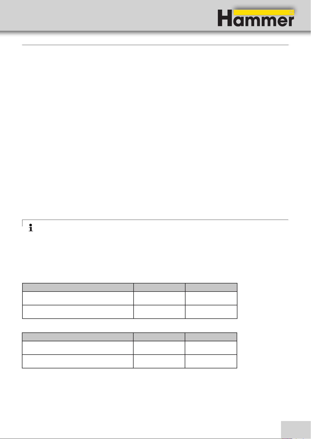
Ø 58 ± 0,1mm
Ø 8,5 ±0,3 mm
Ø 30 mm
Specifications
4.7 Tools
Warning! Risk of injury!
Never exceed the maximum speed indicated on the tool!
4.7.1 Saw unit
Only use saw blades
• Which have an authorised speed higher than the speed of the saw arbor
• which conform to DIN EN 847-1 or DIN EN 847-2 standards
Only use grooving tools designed for wood purposes!
Note: We recommend that only original Hammer tools are used (Hammer catalogue).
The maximum cutting height is directly related to the following factors:
• Type of wood (hardwood or softwood
• Wood dampness
• Feeding speed
• Saw blades
• The motor power of your machine
Sketches: Saw blade Bore with lug
Ø 46,35 ± 0,1mm
Saw-Spindle Moulder
B3 / B3 e-classic
Ø 30 mm
Saw blades
Diameter 250 – 315 mm
Bore with lug *) 30 mm
constant rotation 4800 min-1
Max. cutting height (with a saw blade-diameter 315
103 mm
mm)
Saw blade tiltable from 90° to 45°
*) see sketches
Scoring blades Standard (mechanisch) Option (angetrieben)
Diameter 80 mm 100 mm*)
Bore
Speed 10.000 minˉ¹ 10.000 minˉ¹
Motor power
20 mm 20 mm
- 0,65 kW
Ø 9 ±0,3 mm
*) in Kombination mit 300 mm Hauptsägeblatt
Slotting Cutters CE-Specifications
Max. diameter 180 mm
Width 5 to 20 mm
20
Page 21

Saw-Spindle Moulder
B3 / B3 e-classic
Specifications
4.7.2 Spindle moulder unit
Only use spindle moulder tools,
• which have a max. authorised rotation speed higher than that of the spindle moulder
• which conform to DIN EN 847-1 or DIN EN 847-2 standards and
• which are marked with „MAN“!
Spindle moulder unit
Table opening (Ø) 190 mm
Spindle moulder-Ø max.
Spindle moulder guard 220 mm
Slot guard 275 mm
Spindle-Ø Standard 30 mm
Spindle shaft quick change system Option 1*) 32 / 35 / 50 mm
Spindle shaft quick change system Option 2*) 1 ¼ inch
constant rotation 3000/6000/8000/10000 min-1
Speed High velocity spindle 15000 min-1
Spindle height above table (Usable height) 100mm
Tilting of spindle *) 90° to 45°
* not available with e-classic
4.8 Chip extraction
Saw unit aggregate Saw guard
Dust extraction outlet, Ø 120 mm 50 mm
Min. air speed 20 m/s 20 m/s
Min. vacuum 1824 Pa 953 Pa
Min. volume flow (at 20 m/s) 814 m³/h 141 m³/h
*) Standard = Saw guard / Option = Overhead saw guard
Spindle moulder unit
Dust extraction outlet, Ø 120 mm 120 mm
Min. air speed 20 m/s 20 m/s
Min. vacuum 470 Pa 920 Pa
Min. volume flow (at 20 m/s) 362 m³/h 814 m³/h
*) Standard = Spindle moulder fence / Option = Slotting guard
Spindle moulder
fence Slotting guard
21
Page 22
5 Setting up the machine
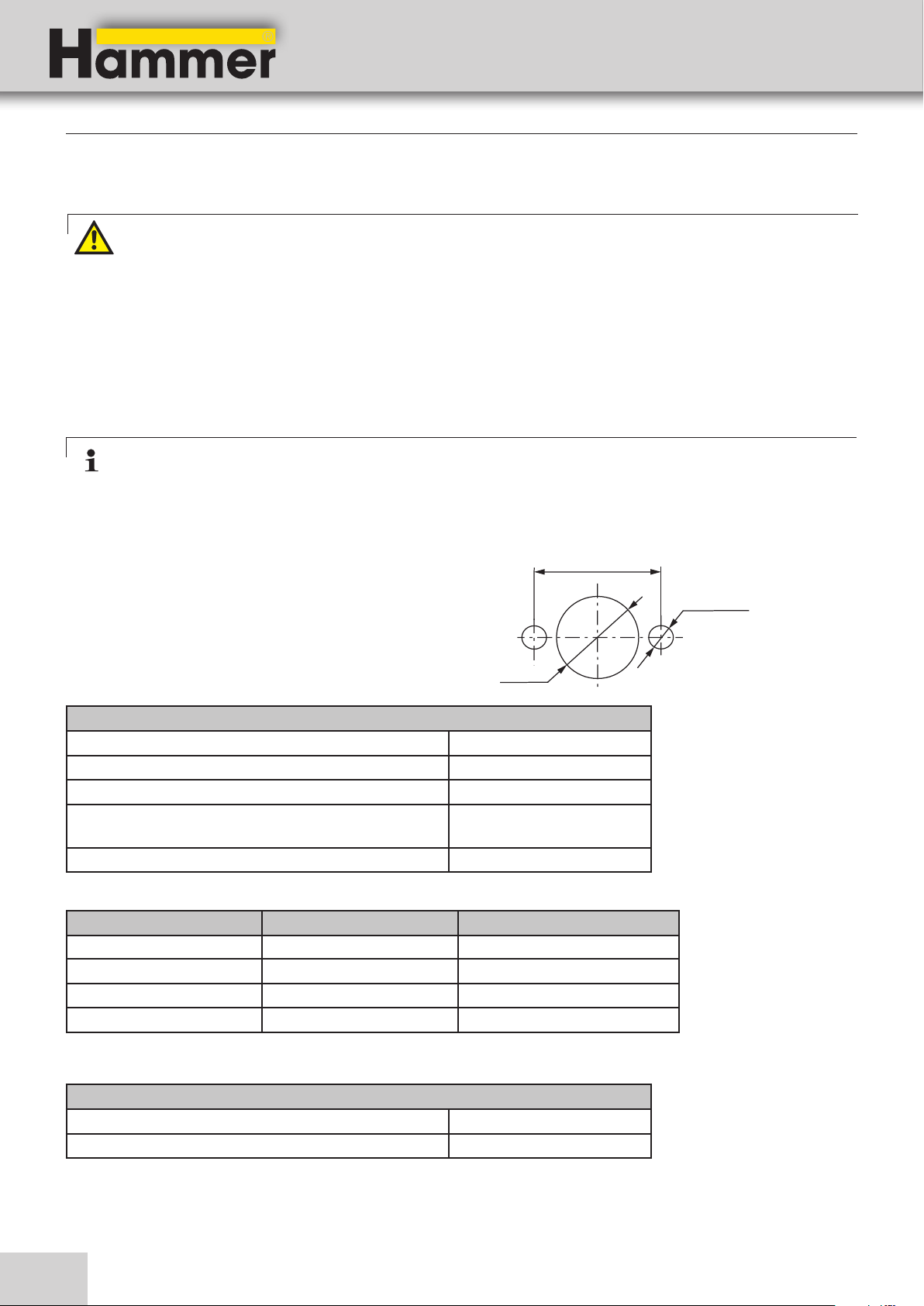
5.1 Overview
% $
"
Saw-Spindle Moulder
B3 / B3 e-classic
Setting up the machine
&
/
!
Fig. 5-1: Overview basic/winner
"
!
#
$
#
Fig. 5-2: Overview perform
!Outrigger arm
"Crosscut fence (Outrigger)
#Outrigger table
$Sliding table
22
%Spindle fence
&Crosscut fence (Outrigger)
/Cross stop
Page 23

Saw-Spindle Moulder
B3 / B3 e-classic
5.2 Accessories
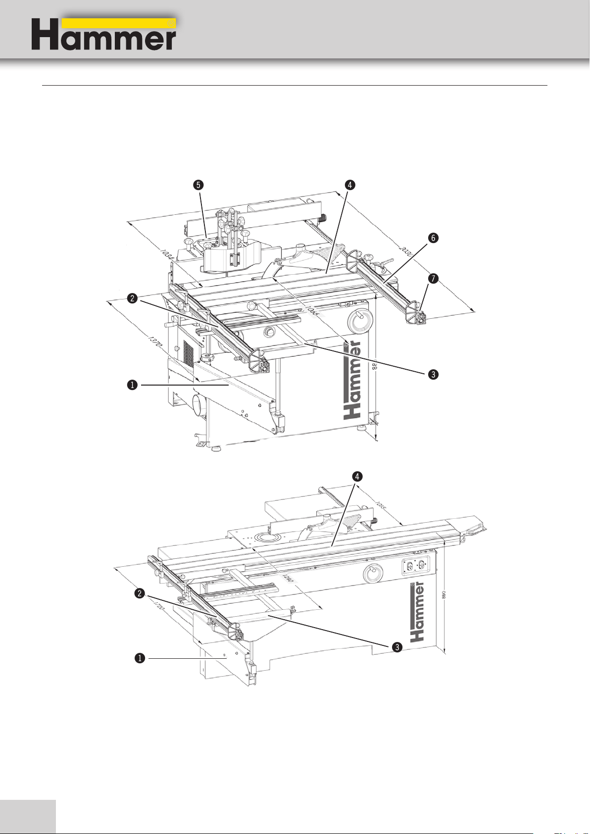
Table extension 400 mm
Order No. 503-137
Setting up the machine
To safely support longer workpieces (assembly instructions „Table extension“).
!Table extension
!
Fig. 5-3: Table extension
Table extension with support leg
Art. No. 501-129
!
Fig. 5-4: Table extension with foot support
Outrigger 1100
Order No. 503-108 (800 x 600 mm)
To safely support longer workpieces (assembly instructions „Table extension“).
!Table extension with foot support
!
Fig. 5-5: Outrigger
To machine large and heavy panels (assembly instructions „Outrigger table“).
!Trimming equipment
23
Page 24
Setting up the machine
Extension with workpiece roller for the outrigger
Order No. 503-132
!
Fig. 5-6: Extension with workpiece roller for the outrigger
Clamp set
Order No. 410-190
Saw-Spindle Moulder
B3 / B3 e-classic
To correctly place very large or very long panels.
!Extension with workpiece roller for the outrigger
Fig. 5-7: Clamp set
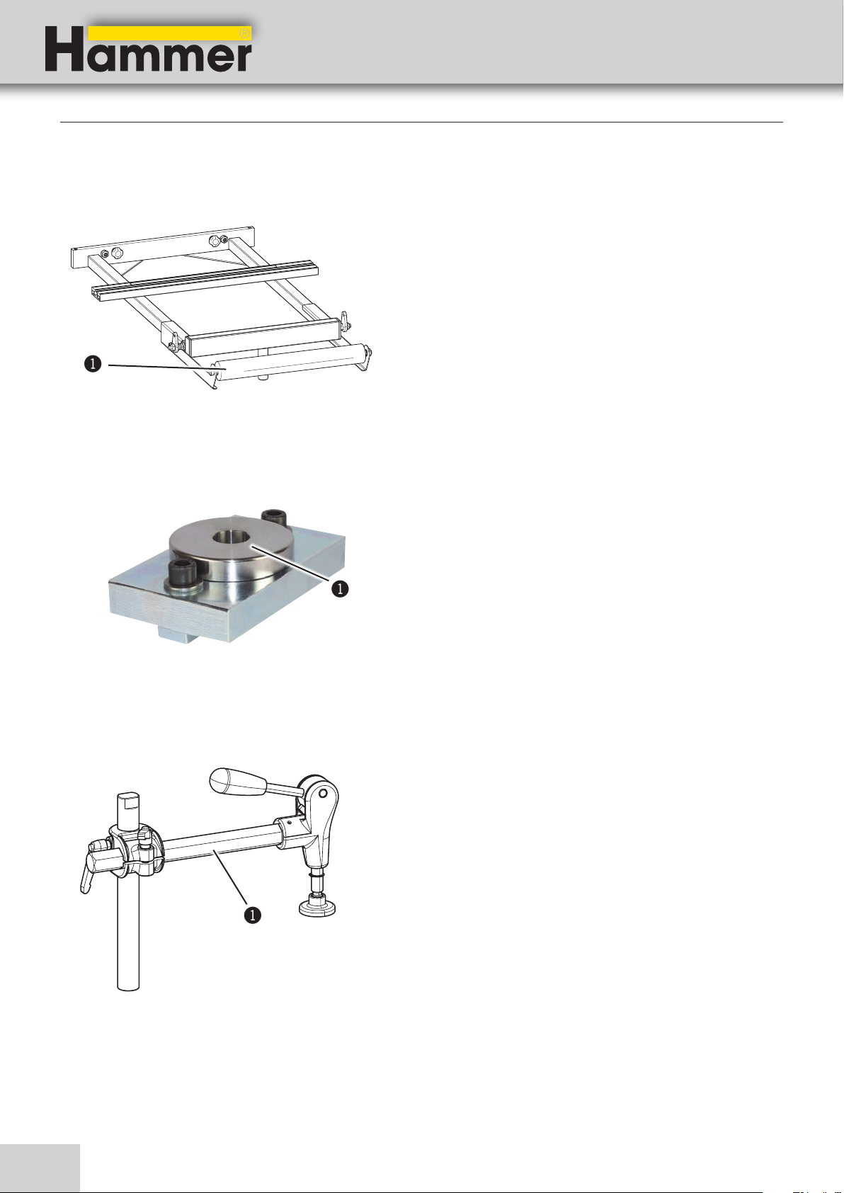
Eccentric clamp
Order No. 400-108 and 500-112
!
For the M20 sliding table with ball guiding system.
To affix the eccentric clamp onto the sliding table.
!Clamp set
!
Can be used horizontally or vertically for any workpiece.
To clamp workpieces securely to the sliding table.
!Eccentric clamp
Fig. 5-8: Eccentric clamp
24
Page 25
Saw-Spindle Moulder
B3 / B3 e-classic
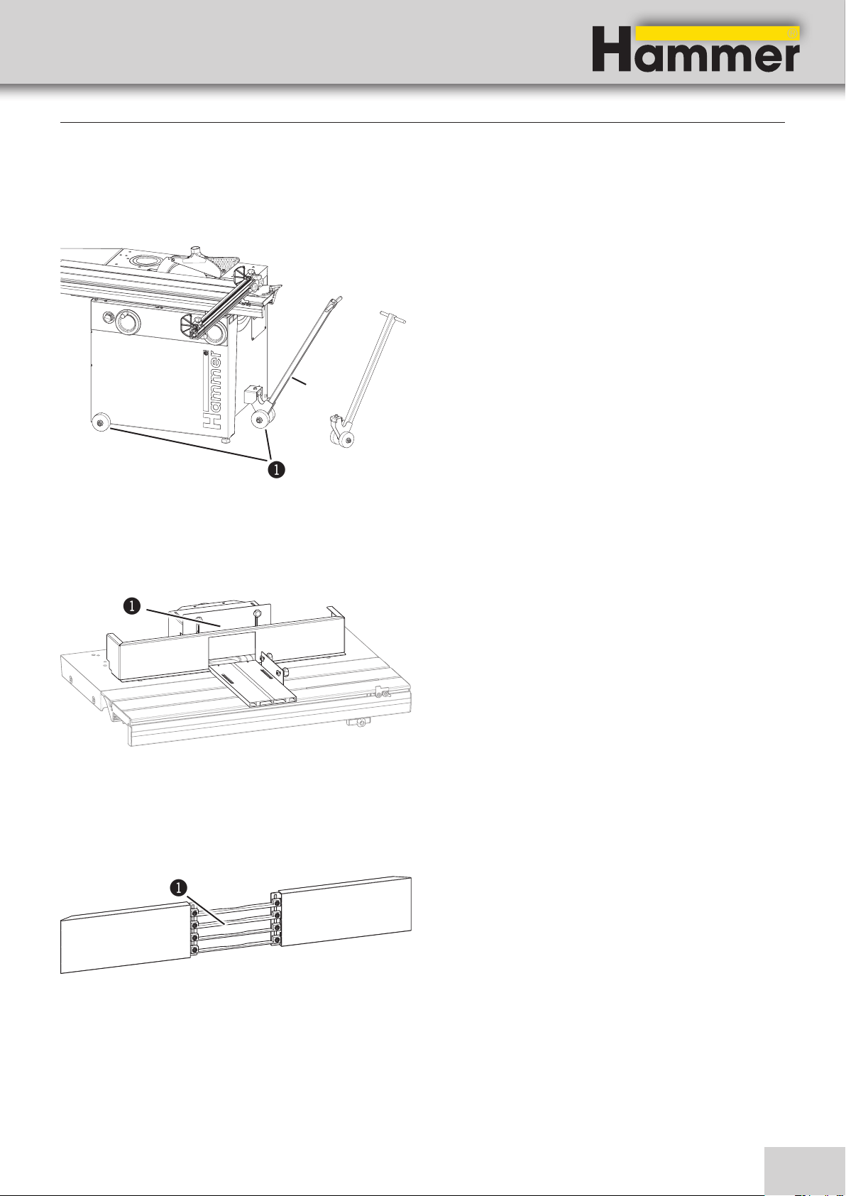
Rolling carriage with lifting bar
Order No. 503-134
500-149
Setting up the machine
Manoeuvring in a small spaces is possible with the lifting
bar and the rolling carriage (assembly instructions „Rolling carriage“).
!Rolling carriage with 4 rollers
"Lifting bar
"
Fig. 5-9: Rolling carriage with 4 rollers
Tenoning cover
Order No. 503-114
!
Fig. 5-10: Tenoning cover
Safety bar guides
Order No. 501-116
!
!
Tenoning and slotting safely.
!Tenoning cover
To protect when moulding profiles.
Fig. 5-11: Safety bar guides
!Safety bar guides
25
Page 26

Digital clock
Order No. 01.1.200 (Display in „mm“)
01.2.200 (Display in „inch“)
System handwheel
Order No. 12.1.311
Saw-Spindle Moulder
B3 / B3 e-classic
Setting up the machine
The digital clock is built into the height adjustment system
handwheel.
Adjustments to 1/10th mm are possible with the digital clock indicator (assembly instructions „Digital clock
indicator“).
"
1
2mm/2˚
Fig. 5-12: Digital clock
EURO Curve moulding guard (ring guard)
Order No. 400-610
!
!
!Digital clock
"System handwheel
For curved moulding tasks with the dust extraction hood
for tools with a diameter of up to 180 mm.
!EURO Curve moulding guard (ring guard)
Fig. 5-13: EURO Curve moulding guard (ring guard)
Workpiece feed guide for the EURO Curve moulding guard
Order No. 400-611
Fig. 5-14: Workpiece feed guide
26
!
Appropriate for tooling Ø 100 – 160 mm.
Smallest possible workpiece inner radius r = 160 mm.
!Workpiece feed guide
Page 27
Saw-Spindle Moulder
B3 / B3 e-classic
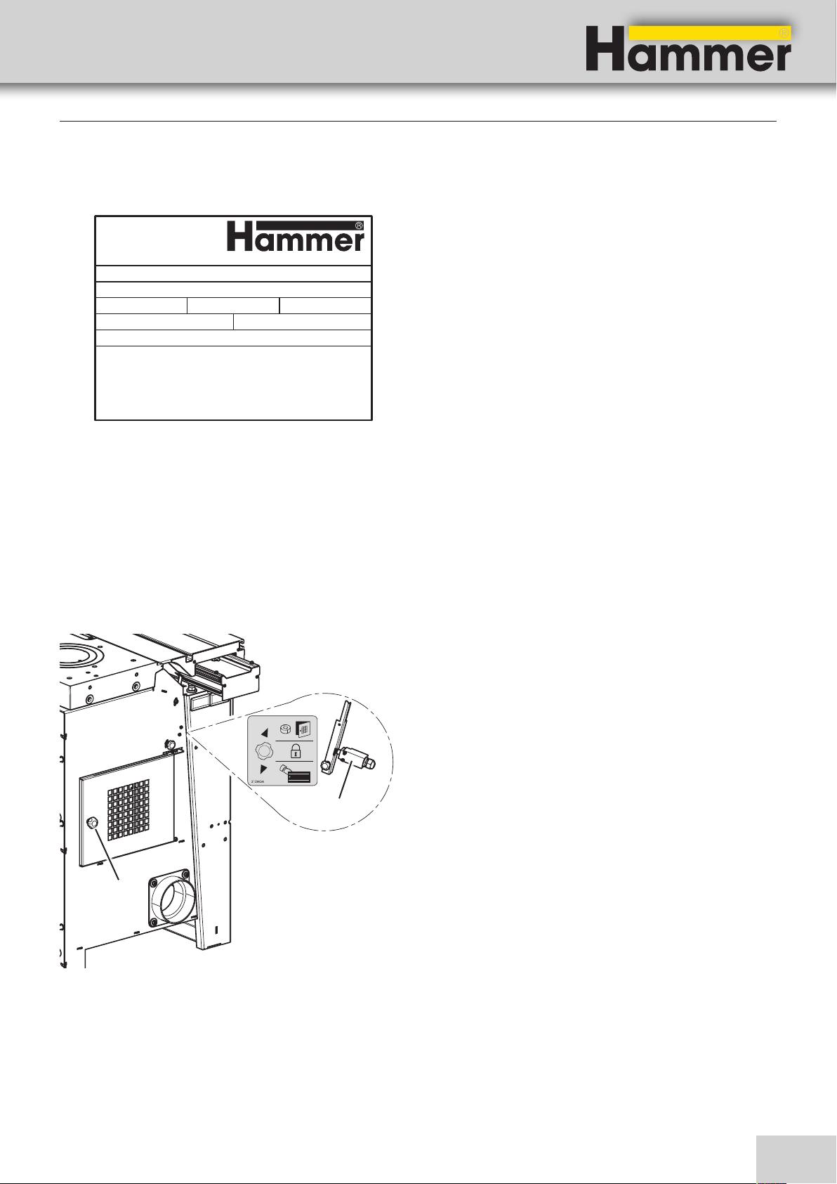
5.3 Data plate
Setting up the machine
KR-FELDER-STR.1
A - 6060 HALL in Tirol
AUSTRIA
Tel.: 0043 (0)5223 / 45 0 90
Tax.: 0043 (0)5223 / 45 0 99
TYPE :
NR. :
Baujahr / year of constr. / annee de constr. :
Motordaten:
Fig. 5-15: Data plate
info@hammer.at / www.hammer.at
A:KW:
5.4 Safety devices
5.4.1 Safety break switches
The data plate displays the following specifications:
• Model designation
• Machine number
• Voltage
• Phases
HZ:PH:V:
• Frequency
• Power
• Electricity
• Year of construction
• Manufacturer info
!
Fig. 5-16: Main switch
Your machine is equipped with safety break switches.
Therefore, the saw blade or the spindle moulder unit can
only operate if the sliding cover is closed.
(The sliding cover and spindle door are closed and the
safety system is in the centre position)
!Break switch
"Spindle moulder door
!
27
Page 28
Setting up the machine
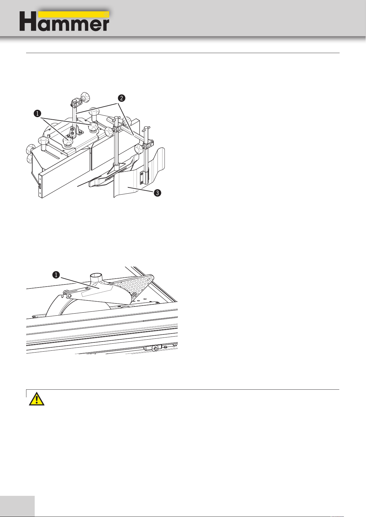
5.4.2 Spindle moulder guard attachment
Saw-Spindle Moulder
B3 / B3 e-classic
"
!
$
Fig. 5-17: Spindle moulder guard attachment
5.4.3 Circular saw guard
!
#
The spindle moulder guard is mounted onto the spindle
moulder fence. It comprises an adjustable rodding, a
pressure shoe and pressure spring.
The individual parts can be adjusted vertically or horizontally with the thumb screw. The vertical pressure shoe
and the horizontal pressure spring are set in such a way
so as to press the workpiece with a slight bias (pressure)
against the table or alternatively the fence boards.
!Thumb screws
"Rodding
#Pressure spring
$Pressure shoe
The saw guard has to be installed and set correctly
Fig. 5-18: Circular saw guard
Warning! Risk of injury! When working with the circular saw blade, the machine‘s saw blade should be
equipped with a saw guard to avoid injuries
The saw guard has to be connected to a dust extractor.
Diameter = 50 mm
!Circular saw guard
28
Page 29
Saw-Spindle Moulder
B3 / B3 e-classic
Setting up the machine
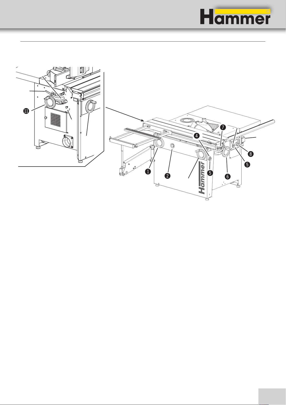
5.5 Operation and display elements
BN
BL
BM
BO
!
Fig. 5-19: Operation and display elements
!Handwheel - Spindle moulder angle adjustment
"EMERGENCY STOP button (if available)
#Handwheel - Circular saw angle adjustment
/
$
$
(
%
!
"
%
&
#
)Mains switch (if available)
BLClamping lever - Spindle moulder angle adjustment
BMHandwheel - Spindle moulder height adjustment
)
$Red push button
• machine OFF
• Emergency-stop
%Green push button - spindle moulder unit ON
&Handwheel - Circular saw angle adjustment
/Scale - Circular saw angle specification
(Mode switch - Operating modes
• Sawing
• Moulding (Anti-clockwise rotating spindle moulder)
• Moulding (Clockwise rotating spindle moulder)
BNScale - moulding angle specification
BOLock system - sliding cover
29
Page 30

Transport, packaging and storage
6 Transport, packaging and storage
6.1 Safety instructions
Warning! There is a risk of injury due to falling parts while transporting, loading or unloading the machine.
Attention! Risk of material damage: The machine can be damaged or destroyed if it is subjected to improper
!
handling during transport.
For this reason the following safety instructions must be
observed:
• Never lift loads over a person.
• Always move the machine with the utmost care and
precaution.
• Only use suitable lifting accessories and hoisting
devices that have a sufficient load-carrying capacity.
• Never transport the machine by putting pressure on
any of its projecting elements (e.g. the planer tables).
• Consider the machine‘s centre of gravity when transporting it (minimise the risk of it tipping over).
• Take measures to prevent the machine from slipping
sideways.
• Ropes, belts or other hoisting devices must be equipped with safety hooks.
Saw-Spindle Moulder
B3 / B3 e-classic
• Do not use torn or worn ropes.
• Do not use knotted ropes or belts.
• Ensure that ropes and belts do not lie against sharp
edges.
• Transport the machine as carefully as possible in
order to prevent damage.
• Avoid subjecting the machine to shocks.
• When transporting the machine overseas, ensure
that the packaging is air-tight and that a desiccant is
added to protect the metal parts against corrosion.
6.2 Transport methods
Attention! Risk of material damage! The machine must not be lifted by the work table, sliding table or base!
!
Fig. 6-1: Transport methods
The machine is completely assembled when delivered on
the pallet.
Use any of the following to unload:
• Forklift truck,
• Pallet jack,
• Crane
• Rolling carriage
Only use belts or chains to transport the machine.
30
Page 31

90 x 90 mm
70 x 70 mm
40 x 40 mm
950 x 750 x 25 mm
Saw-Spindle Moulder
B3 / B3 e-classic
Transport, packaging and storage
6.2.1 Transport with a pallet jack
Attention! Heavy dead weights can easily cause an injury
Depending on the equipment, two or three additional helpers may be necessary when unloading.
"
Use a loading platform similar to the one depicted in the
picture opposite to unload from the pallet.
1. Push the forks under the gaps in the machine frame.
2. Unload the machine from the pallet with the fork
carriage truck.
!Cutout hole in the machine frame
"Unloading ramp
!
Fig.6-2: Transport with a pallet jack
6.2.2 Transport with a rolling carriage
Attention: The rolling carriage and the lifting bar (option) facilitate the task of transporting the machine.
"
!
Fig. 6-3: Transporting the machine with the rolling carriage and
lifting bar
The rolling carriage is mounted to the machine base.
!Rolling carriage with 4 rollers
"Lifting bar
31
Page 32

6.3 Transport inspection
Saw-Spindle Moulder
B3 / B3 e-classic
Transport, packaging and storage
Upon arrival, inspect the shipment to ensure that it is
complete and has not suffered any damage.
If any transport damage is visible, do not accept the delivery or accept it only with reservation. Record the scope
of the damage on the transport documents/delivery note.
Initiate the complaint process.
6.4 Packaging
If no agreement has been made with the supplier to
take back the packaging materials, help to protect the
environment by reusing the materials or separating them
according to type and size for recycling.
Attention! Dispose of the packaging materials in an environmentally friendly way and always in accordance
with local waste disposal regulations. If applicable, contract a recycling firm to dispose of the packaging
materials.
Attention: Help preserve the environment! Packaging materials are valuable raw materials and in many
cases, they can be used again or expediently reprocessed or recycled.
For all defects that are not discovered upon delivery, be
sure to report them as soon as they are recognised as
damage claims must be filed within a certain period, as
granted by law.
6.5 Storage
Keep items sealed in their packaging until they are assembled/installed and be sure to observe the stacking
and storage symbols on the outside of the packaging.
Store packed items only under the following conditions:
• Do not store outdoors.
• Store in a dry and dust-free environment.
• Do not expose to aggressive substances.
• Protect from direct sunlight.
• Avoid subjecting the machine to shocks.
• Storage temperature: -10° to +50° C.
• Maximum humidity: 60%.
• Avoid extreme temperature fluctuations (condensation
build-up).
• Apply a coat of oil to all bare machine parts (corrosion protection).
• When storing for a period longer than 3 months, apply a coat of oil to all bare machine parts (corrosion
protection). Regularly check the general condition of
all parts and the packaging. If necessary, refresh or
re-apply the coat of anti-corrosive agent.
• If the machine is to be stored in a damp environment,
it must be sealed in air-tight packaging and protected
against corrosion (desiccant).
32
Page 33

Saw-Spindle Moulder
B3 / B3 e-classic
7 Setup and installation
7.1 Safety instructions
Warning! Risk of injury: Improper assembly and installation can lead to serious bodily injury or equipment
damage. For this reason this work may only be carried out by authorised, trained personnel who are familiar
with the operation of the machine and in strict observance of all safety instructions.
Setup and installation
• Ensure that there is sufficient space to work around
the machine. If there is not sufficient distance
between the machine and neighbouring machines,
walls or other solid objects, the rail-guided workpieces pose a risk during the sawing process.
Warning! Danger – electric current: Work on electrical fittings may only be carried out by qualified personnel
and in strict observance of the safety instructions.
Before assembling and installing the machine, check to
make sure it is complete and in good condition.
Warning! Risk of injury: An incomplete, faulty or damaged machine can lead to serious bodily injury or
equipment damage. Only assemble and install the machine if the machine and its parts are complete and
intact.
Attention! Risk of material damage: Only operate the machine in ambient temperatures from +10° to
!
+40° C. If the instructions are not followed, damage may occur during storage.
• Keep the work area orderly and clean. Components
and tools that are not put in their correct place or put
away may be the cause of accidents!
• Install the safety equipment according to the instructions and check that it functions properly.
7.2 Installation
Fig. 7-1: Space requirements/Measurements
Installation site requirements:
• Operating/room temperature: +10° to +40°C.
• Ensure that the work surface is sufficiently stable and
has the proper load-bearing capacity.
• Provide sufficient light at the workstation.
• Ensure there is sufficient clearance for or from
neighbouring workstations.
To operate and maintain the machine, leave a min. of
2000 mm space all around the machine.
33
Page 34

Setup and installation
7.3 Positioning and levelling the machine
Saw-Spindle Moulder
B3 / B3 e-classic
!
"
Fig. 7-2: Positioning the machine
1. Transport the machine to the installation site as
instructed in the “Transport“ chapter and the enclosed transport or installation instructions.
2. Position the machine with the aid of a spirit level
to ensure that the machine functions precisely and
operates smoothly.
If the floor is uneven, use blocks to level the machine.
!Spirit levels
"blocks
3. If necessary, the machine can be bolted down to the
floor with the transport brackets.
!Transport brackets
Fig. 7-3: Floor mounting
Fig. 7-4: Transport locking device Sliding table
34
!
4. Before operating the machine, remove the wedges
from the lower tracks and sliding table on both sides.
5. Remove the oxidation protective layer from all blank
machine parts.
Page 35

Saw-Spindle Moulder
B3 / B3 e-classic
Setup and installation
7.4 Assembly
7.4.1 Sliding table
Attention: Due to transport reasons, the sliding table, depending on its length, may be packaged
separately. Two to three additional helpers, depending on the cutting length, are required to install the
machine.
The sliding table has to be set up before the initial machine start-up. Individual installation instructions are found
with the machine or the sliding table.
7.4.2 Assembling/disassembling the outrigger table
$
!
"
#
Fig. 7-5: Assembling the outrigger table
7.4.3 Spindle moulder fence
Assembling the outrigger table:
1. Hook the outrigger table into the groove on the
sliding table.
2. Place the outrigger table onto the support arbor.
3. Fix with a thumb screw.
Disassembling the outrigger table:
1. Loosen the thumb screw.
2. Unhook the outrigger table from the support arbor
and the sliding table.
!Groove
"Outrigger table
#Support arbor
$Thumb screws
The spindle moulder fence is completely assembled upon
delivery and is mounted to the machine.
If transported in a container, the spindle moulder fence is
mounted and delivered separately from the pallet. In this
case, the spindle moulder fence has to be placed onto
the machine and fastened securely.
Fig. 7-6: Spindle moulder fence
35
Page 36

7.4.4 Circular saw guard
Saw-Spindle Moulder
B3 / B3 e-classic
Setup and installation
!
"
§
$
%
&
Fig. 7-7: Circular saw guard
! Splitter
" Thumb nut
§ Hood stud
$ Circular saw guard
% Recess for saw blades from 300 to 315 mm
& Recess for saw blades from 250 mm
7.5 Chip extraction
The saw guard is mounted onto the splitter. The mounting
depends on the diameter of the saw blade:
• Recess for saw blades from 300 to 315 mm
• Recess for saw blades from 250 mm
1. Loosen the thumb nut.
2. Push the hood stud to the back with the thumb nut.
3. Circular saw guard Remove the saw guard and insert
it into the other recess.
4. Tighten the thumb nut.
Warning! Risk of injury! Vacuum hose must be flame-resistant and must conduct electricity! Be sure to use only
genuine Hammer vacuum hoses!
Note: As a rule, all units must be vacuumed during use. A time delayed socket is available as an accessory.
• In addition, the vacuum performance must be sufficient
to achieve the required negative pressures and an air
speed of 20 m/s at the connector. (see “Technical
data”)
• Check the air speed before putting the machine into
operation for the first time and after essential changes.
• The dust extractor setup must be controlled before the
machine is put into operation for the first time. Check for
obvious defects on a daily basis and the efficiency on a
monthly basis.
• The dust extractor must be connected to the machine
in such a manner that it runs in unison with the
machine.
• The dust extraction hoses must be electrically conductive and grounded to prevent electrostatic
build up.
• Use dust extractors with reduced dust emission to clean
dust from the machine.
36
Page 37

Saw-Spindle Moulder
B3 / B3 e-classic
7.6 Electrical connection
Warning! Danger! Electric current!
Work on electrical fittings may only be carried out by qualified personnel and in strict observance of the safe-
ty instructions.
Checking the loop impedance and the suitability of the overcurrent protective device must take place at the
location where the machine is to be commissioned!
Attention! Risk of material damage!
!
Before hooking up the machine to the power supply, compare the specifications on the data plate with those
of the electrical network. Only hook up the machine if the two sets of data correspond to each other. The
electrical outlet must have the appropriate socket (for a three-phase alternating current motor, CEE).
Setup and installation
Note: Do not open the machine‘s switch box unless you have the express consent of the Hammer service department Violating this stipulation shall render the right to make claims under the warranty null and void.
Attention! Risk of material damage!
!
The machine must be secured with an automatic fuse.
!
"
Fig. 7-8 Direction of the Motor rotatation
1. Set the mode switch to the „Circular saw“ setting.
2. Connect the plug to the power supply.
3. Switch on and let the machine run briefly.
4. While the motor is running, check its direction of
rotation.
5. Should a change in the direction of rotation be
necessary, switch the two phases on the power cable.
Electrical connection requirements
• The machine must be earthed with electrical
conductors.
• The voltage fluctuations in the mains supply may not
exceed ±10 %.
• The switch cabinet must be fitted with a circuit
breaker (DIN VDE 0641).
Number of terminals: 3 (three phase current motors)
• The unit must only be used in TN-Systems (neutral
connected to earth)! (only 3x400V)
• Power supply cable H07RN-F at least 5x 2,5 (rotarycurrent motor) or 3x 2,5 (alternating-current motor).
• Safeguarding/Power supply cord:
see “Technical data”
• The power supply cable must be protected against
damage (e.g. armoured conduit).
• The power supply cable must be laid in such a way
so it does not overbend or chafe and there is no risk
of tripping over it.
! CEE-Plug
Š Phase inverter (optional)
Note: The machine‘s power cable is delivered with an open cable end, i.e. without a plug.
The operator is responsible for fitting the machine‘s power cable with a suitable plug in accordance with any
country’s specific regulations.
37
Page 38

Making adjustments and preparations
8 Making adjustments and preparations Saw unit
8.1 Safety instructions
Warning! Risk of injury: Improper adjustment and working setup can lead to serious bodily injury or material
damage. For this reason this work may only be carried out by authorised, trained personnel who are familiar
with the operation of the machine and in strict observance of all safety instructions.
Saw-Spindle Moulder
B3 / B3 e-classic
• Before beginning any maintenance work on the machine, switch it off and secure it against accidentally
being switched on again.
• Before commencing any work with the machine, inspect it to ensure that it is complete and in technically
good condition.
Warning! Danger – electric current: Work on electrical fittings may only be carried out by qualified personnel
and in strict observance of the safety instructions.
8.2 Sliding table catch
• Ensure that there is sufficient space to work around
the machine.
• Keep the work area orderly and clean. Components
and tools that are not put in their correct place or put
away may be the cause of accidents!
• Install the safety equipment according to the instructions and check that it functions properly.
The sliding table can be locked into the centre position.
1. Rotate the thumb screw by 90° and push in.
2. Move the sliding table slowly into the locked positi-
on, until it engages.
3. To unlock, pull out the thumb screw and rotate 90°
anti-clockwise.
Fig. 8-1: Sliding table locking system
38
!
! Thumb screw
" Sliding table
"
Page 39

Saw-Spindle Moulder
B3 / B3 e-classic
Making adjustments and preparations
8.3 Crosscut fence on the sliding table
%
&
Fig. 8-2: Assembling the crosscut fence
!
$
"
#
1. Thread the clamping device of the crosscut fence into
the groove of the sliding table and move it right up to
the stop screw (in the groove).
2. Loosely affix the compressor rod shaft.
3. Adjust the desired cutting angle (-45° to +45°).
With 90° cuts:
• Flip open the end stop on the sliding table.
• Place the fence against the end stop.
4. Clamp the stop with the clamping lever.
! Compressor rod shaft $Clamping device
" Single-hand clamp lever %End stop
# Groove &Stop
Adjusting:
1. Fold the end stop back.
2. Loosen the setscrew.
3. Turn the cam lever until a 90° angle is attained (the
fence reaches the end stop).
4. Check with a sample cut.
5. Tighten the setscrew.
!
Fig. 8-3: Adjusting the end stop
8.4 Crosscut fence on the outrigger
"
#
!
"
&
%
$
#
! End stop
" Setscrew
# Cam lever
The crosscut fence can be mounted onto the outrigger on
the push side.
1. Thread the locking plate into the outrigger rail.
2. Loosen the thumb screws and position the crosscut
fence at the outrigger.
3. Clamp the crosscut fence at the outrigger with the
clamping lever.
4. Tighten the thumb screws.
! Clamping lever $Outrigger
" Crosscut fence %Locking plate
# End stop &Thumb screws
Fig. 8-4: Assembling the crosscut fence
39
Page 40

!
&
%
Fig. 8-5: Adjusting the crosscut fence
Making adjustments and preparations
Pivoting:
&
$
"
#
1. Loosen the clamping lever and thumb screws.
2. Pivot the crosscut fence to the desired position. Fold
the end stop back if necessary, so as to be able to
pivot the crosscut fence over it.
3. Clamp the clamping lever in place and tighten the
thumb screws.
4. Loosen the thumb screws, move the fence profile and
retighten the thumb screws in order to compensate
the length of the scale when the fence is pivoted.
! Clamping lever
" Crosscut fence
# End stop
$ Outrigger
% Locking plate
& Thumb screws
Saw-Spindle Moulder
B3 / B3 e-classic
8.5 Cross stop
Fig. 8-6: Cross stop
%
$
!
"
#
90°-Position:
1. Loosen the clamping lever and thumb screws.
2. Pivot the crosscut fence, until it stops against the end
stop.
3. Clamp the clamping lever in place and tighten the
thumb screws.
The cross stop can be pushed onto the crosscut fence in
one movement.
If required, the end stop can be folded back.
1. Loosen the thumb screw.
2. Move the cross stop to the desired position. The
measurement (rip capacity) reading is read from the
magnifying lens.
3. Tighten the thumb screw.
! Thumb screws
" Cross stop
# Scale
$ End stop
% Crosscut fence
40
Page 41

Saw-Spindle Moulder
B3 / B3 e-classic
Making adjustments and preparations
8.6 Crosscut fence-extension
$
!
"
The crosscut fence may be fitted with an extension as an
option.
1. Loosen the thumb screw.
2. Move the crosscut fence extension to the desired
measurement.
The measurement (cutting width), is read from the
scale on the profile edge of the crosscut fence.
3. Tighten the thumb screw.
#
Fig. 8-7: Crosscut fence-extension
8.7 Parallel cutting fence
8.7.1 Sliding
!
Fig. 8-8: Parallel cutting fence B3 e-classic
"
#
$
%
! Scale
" Extension
# Thumb screw
$ Crosscut fence
B3 e-classic:
1. Loosen the clamping lever.
2. Read the dimension from the scale on the front edge
of the indicator.
3. Move the scale by the measurement required to
adapt the scale to the different widths of the saw
blade:
- Loosen the four flat nuts on the track.
- Move the track.
- Retighten the four flat nuts.
4. Clamp the clamping lever.
! Scale $Track
" Indicator %Nuts
# Clamping lever
Attention! When using a table extension, the distance between the upper edge of the track and the upper
edge of the table has to measure 17 mm exactly so that the position of the table extension is level with that
of the table.
41
Page 42

$
!
"
Fig. 8-9: Parallel cutting fence B3 winner
8.7.2 Fine adjustment
Making adjustments and preparations
B3 winner:
1. Loosen the knurled handle.
2. Read the dimension from the scale on the front edge
of the indicator.
3. Move the scale by the measurement required to
adapt the scale to the different widths of the saw
blade:
-Loosen the locking plate.
- Move the scale.
- Tighten the locking plate.
#
4. Lock the knurled handle.
! Scale #Knurled handle
" Indicator $Locking plate
Saw-Spindle Moulder
B3 / B3 e-classic
"
!
#
Fig. 8-10: Parallel cutting fence K3 basic/K3 e-classic
Attention: Always carry out the adjustment towards the circular saw to be able to compensate for the thread
clearance.
K3 e-classic (Option):
1. Loosen the clamping lever 1.
2. Lock the clamping lever 2.
3. Adjust finely with the thumb nut.
! Clamping lever 1
" Clamping lever 2
# Thumb nut
K3 winner:
1. Loosen the knurled handle.
2. Press the thumb nut inwards.
3. Adjust finely by turning the thumb nut.
4. Tighten the knurled handle following the fine adjust-
ment.
!
Fig. 8-11: Parallel cutting fence K3 winner
42
"
! Knurled handle
" Thumb nut
Page 43

Saw-Spindle Moulder
B3 / B3 e-classic
8.7.3 Modifying the guide
"
Fig. 8-12: Parallel cutting fence
8.7.4 Removal
Making adjustments and preparations
!
1. Loosen the thumb screw.
2. Pull out the guide to the front.
3. Place the guide flat onto the table and once again,
thread through the appropriate groove.
4. Tighten the thumb screws.
! Thumb screw
" Guide
!
"
Fig. 8-13: Parallel cutting fence B3 e-classic
#
$
"
B3 e-classic:
It may be necessary to remove the rip fence when machining large panels.
1. Loosen the clamping lever 1.
2. If present: Loosen the fine adjustment clamping lever
by 5-6 turns.
3. Remove the parallel cutting fence from the track from
the top.
! Rip fence #Single-hand clamping lever
" Clamping lever 1 $Track
B3 winner:
It may be necessary to remove the parallel cutting fence
when machining large panels.
1. Loosen the knurled handle.
2. Remove the parallel cutting fence from the back of
the bar.
!
Fig. 8-14: Parallel cutting fence B3 winner
#
! Knurled handle
" Parallel cutting fence
# Bar
43
Page 44

8.7.5 Swinging out
Attention: Swinging out is only possible with the K3 winner circular saw.
Saw-Spindle Moulder
B3 / B3 e-classic
Making adjustments and preparations
Swinging the parallel cutting fence out may be necessary
e.g. to machine large panels.
#
!
"
Fig. 8-15: Parallel cutting fence
8.8 Setting the height/angle of cut
$
%
1. Loosen the thumb screw.
2. Place the guide in the centre.
3. Clamp the thumb screw.
4. Loosen the knurled handle.
5. Move the parallel cutting fence right up to the end of
the bar.
6. Swing out the parallel cutting fence.
! Guide $Thumb screw
" Knurled handle %Bar
# Parallel cutting fence
The cutting height is set with the handwheel:
!
Fig. 8-16: Setting the height/angle of cut
44
#
"
• Clockwise: higher
• Anti-clockwise: lower
Only set the cutting height to the required height.
The cutting angle is set with the handwheel:
• Clockwise: towards 0°
• Anti-clockwise: towards 45°
The cutting angle is displayed on the scale.
!Handwheel cutting angle
"Scale cutting angle
#Handwheel cutting height
Page 45

Saw-Spindle Moulder
B3 / B3 e-classic
Making adjustments and preparations
8.9 Tool change
8.9.1 Preparing to change tooling
"
1. Tilt the circular saw into a 90° position
Move the circular saw right up to the top
2. Switch the machine off and ensure that it cannot be
switched on again.
3. Push the lock downwards.
4. Slide the sliding table to the right until it reaches its
limit.
5. Slide the sliding cover to the left until it reaches the
stop.
#
Fig. 8-17: Preparing to change tooling
!
8.9.2 Preparing the machine to operate
"
#
Fig. 8-18: Prepare the machine to operate
!
!Sliding table
"sliding cover
#Lock system
1. Slide the sliding cover to the right until it reaches the
stop.
2. Move the sliding table to the left.
3. Push the lock to the top.
4. Switch machine on
!Sliding table
"sliding cover
#Lock system
Note: The saw blade only operates if the break switch inside the machine frame has not been activated by
the locking system: the sliding cover is closed
• The sliding cover and spindle door are closed and the safety system is in the centre position
45
Page 46

Making adjustments and preparations
8.10 Changing the saw blade
Warning! Risk of injury!
Be wary of sharp edges to avoid cutting yourself, in particular when changing the tooling.
Note:
We recommend that only original Hammer tools are used (Hammer catalogue).
For precision cutting, we recommend you to use the smallest saw blade possible.
See technical data for authorised saw blades.
§
!
Fig. 8-19: Changing the saw blade
"
$
Saw-Spindle Moulder
B3 / B3 e-classic
Required tools:
• Hex key 8 mm
• Spanner SW 22 mm
1. Prepare to change tooling..
2. Loosen the splitter to install a larger saw blade.
3. Hold the flange tight with the spanner.
4. Loosen the socket head cap screw with an hex key.
5. Remove the socket head cap screw and flange.
6. Remove the old saw blade and place the new saw
blade on the arbor.
7. Replace the flange (take note of the assembling
position). Hold the flange tight with the spanner.
8. Screw in the socket head cap screw with the hex key.
9. Adjust the splitter if a larger or smaller saw blade
has been fitted in.
10. Prepare the machine to operate.
11. Adjust the saw guard according to the saw blade.
! Splitter
" Flange
§ Socket head cap screw
$ Saw blade
Attention! Minimum tightening torque: 20 Nm!
46
Page 47

d = S + mm < D
d
2
Saw-Spindle Moulder
B3 / B3 e-classic
Making adjustments and preparations
8.10.1 Loosening/adjusting the splitter
Warning! Risk of injury!
The splitter has to be adapted to the thickness of the saw blade.
The thickness of the splitter has to have a value between that of the saw blade body and the width of the
sawtooth.
"
#
$
%
!
Fig. 8-20: Adjusting the splitter
Attention! Minimum tightening torque: 25 Nm!
8.10.2 Fitting in/changing the splitter
Note:
The thickness of the splitter must be between that of the saw blade body and the width of the sawtooth.
Splitter thickness (d), saw blade body (S), sawtooth width (D)
Required tools:
• Spanner SW19 mm
1. Prepare to change tooling.
2. Loosen the nut.
3. Move the splitter so that there is, at any given point,
a distance of 3 to 8 mm betweeen the saw blade
and the splitter.
4. The marking on the splitter must match the top edge
of the sliding table at the max. cutting height (independently of the saw blade used).
5. Tighten the nut.
!Nut $Distance
"Marking %Saw blade
#Splitter
The splitter has to be adapted to the thickness of the saw
blade.
D
Required tools:
• Spanner SW 19 mm
1. Loosen the locking nut.
2. Remove the splitter if required.
3. Insert the splitter.
Take care that the splitter holder studs fit in the
splitter groove.
4. Tighten the locking nut.
!
10
S
"
!Locking nut #Shim
"Splitter $Bolts
Fig. 8-21: Fitting in/changing the splitter
Attention! Minimum tightening torque: 25 Nm!
%Saw blade
47
Page 48

Making adjustments and preparations
8.10.3 Removing the splitter
Attention!
A splitter is required when working with circular saw blades!
Operation without the splitter is only allowed if dado tooling is used!
"
Saw-Spindle Moulder
B3 / B3 e-classic
1. Loosen the nut.
2. Remove the splitter.
3. Tighten the nut.
!
Fig. 8-22: Removing the splitter
8.10.4 Circular saw guard
Warning! Risk of injury!
When working with the circular saw blade, the machine‘s saw blade should be equipped with a saw guard
to avoid injuries!
ø 300
ø 315
ISK 3
min 2 mm
max 4 mm
"
ø 250
§
$
!Nut
"Splitter
The saw guard is mounted onto the splitter. The mounting
depends on the diameter of the saw blade:
• Recess for saw blades from 300 to 315 mm
• Recess for saw blades from 250 mm
1. Loosen the thumb nut.
2. Push the hood stud to the back with the thumb nut.
3. Remove the saw guard and insert into the other re-
cess.
4. Secure the thumb nut.
!
Fig. 8-23: Circular saw guard
48
&
%
!Splitter
"Hood stud
§Thumb nut
$Circular saw guard
%Recess for saw blades from 300 to 315 mm
&Recess for saw blades from 250 mm
Page 49

Saw-Spindle Moulder
B3 / B3 e-classic
8.11 Grooving tools
Warning! Risk of injury!
Be wary of sharp edges to avoid cutting yourself, in particular when changing the tooling.
Note:
We recommend that only original Hammer tools are used (Hammer catalogue).
For authorised grooving tools see the Technical data section.
Attention! Risk of material damage!
!
Do not adjust the 90° angle when operating with grooving tooling!
Making adjustments and preparations
8.11.1 Retooling to an operation with grooving tools
!
#
"
$
Required tools:
• Hex key 8 mm
• Hex key 4 mm
• Spanner SW 22 mm
• Spanner SW 19 mm (Splitter)
1. Prepare to change tooling.
2. Remove the saw blade
3. Remove the splitter
4. Remove the rear flange.
5. If required, remove the scoring blade.
6. Unscrew the 4 screws with the allen key.
7. Remove the loading board.
%
&
! Synthetic insert
Fig. 8-24: Rear flange/Splitter holder/Loading board
" Screws
# Hex key
(
/
$ Flange
% Splitter holder
& Nut
$
/ Spacer ring (Rear flange)
( Saw blade arbor
Fig. 8-25: Spacer ring/Saw arbor
49
Page 50

Making adjustments and preparations
8.11.2 Chucking the grooving tools
Attention! A spacer ring has to be placed onto the saw blade arbor if using grooving tools with a width
measuring less than 10 mm!
Saw-Spindle Moulder
B3 / B3 e-classic
$
!
Fig. 8-26: First part of the grooving tool/Spacer washers
#
Fig. 8-27: Fit grooving tooling in
$
"
^
%
1. Place the first part of the grooving tool onto the saw
blade arbor. Take note of the correct rotational
direction!
2. Adjust the grooving width with spacer washers.
3. Place the second part of the grooving tool onto the
saw blade arbor. Both tooling halves have to grip
into one another!
4. Attach the grooving tool flange.
5. Hold the flange tight with an open-ended spanner.
6. Screw in the socket head cap screw with the hex key.
! Saw blade arbor
"Grooving tool flange
# Hex key
$ Grooving tool
% Spanner
& Spacer washers
Attention! Risk of injury! Minimum tightening torque: 20 Nm!
Grooving tools may only be clamped with appropriate grooving tool flanges.
/ (
Fig. 8-28: Wooden loading board
Attention! Do not adjust the 90° angle when operating with grooving tooling!
7. Lower the circular saw unit down as far as it goes
8. Mount the wooden insert supplied.
9. Screw in the 4 screws with the Allen key.
10. Prepare the machine to operate.
11. Switch machine on.
12. Slowly, move the grooving tool right to the top and
the wooden loading board will as a result be milled
out.
/ Wooden insert
( Hex key
50
Page 51

Saw-Spindle Moulder
B3 / B3 e-classic
Making adjustments and preparations
8.11.3 Unchucking the grooving tools – Retool to a saw blade operation
!
Fig. 8-29: Wooden loading board
%$ &
Fig. 8-30: Remove grooving tooling
#
"
Required tools:
• Hex key 8 mm
• Spanner SW 22 mm
• Hex key 4 mm
1. Prepare to change tooling.
2. Move the grooving tool to the lowest position.
3. Unscrew the 4 screws with the allen key.
4. Remove the wooden insert.
5. Hold the circular saw flange with an open-end
spanner.
6. Loosen the socket head cap screw with an hex key.
(8 mm )
7. Remove the socket head cap screw and flange.
8. Remove the grooving tool.
9. Remove the spacer ring from the saw blade arbor if
present.
! Wooden insert
@ Screws
# Hex key 4 mm
$ Hex key 8 mm
% Grooving tool
& Spanner
/
"
(
Fig. 8-31: Rear flange/Loading board
#
10. Place the synthetic insert into position.
11. Screw in the 4 screws with the Allen key.
12. Mount the rear flange.
13. Assemble the saw blade.
/ Synthetic insert
( Flange
51
Page 52

Making adjustments and preparations
8.12 Scoring blade
Warning! Risk of injury!
Be wary of sharp edges to avoid cutting yourself, in particular when changing the tooling.
Note:
We recommend that only original Hammer tools are used (Hammer catalogue).
For authorised scoring tools see the Technical data section.
8.12.1 Assembling the scoring blade
Saw-Spindle Moulder
B3 / B3 e-classic
Required tools:
• Hex key 5 mm
• Special spanner
#
$
!
Fig. 8-32: Lock washer/Scoring arbor
%
"
&
Assembling the scoring blade
1. Prepare to change tooling.
2. Turn the lock washer to the left as far as it goes.
3. Clean the scoring arbor thoroughly.
4. Place the scoring blade onto the scoring arbor.
5. Fit the scoring flange on and hold in place with the
special spanner.
6. Tighten the flat-head screw clockwise with an allen
key;
Disassembling the scoring blade
1. Prepare to change tooling.
2. Hold the scoring flange with the special spanner.
3. Loosen the flat-head screw anti-clockwise with an
allen key.
4. Place the scoring blade onto the scoring arbor.
5. Pull the scoring blade from the arbor.
6. Turn the lock washer to the right until it stops.
! Lock washer
@ Scoring arbor
# Scoring blade
$ Scoring flange
% Flat-head screw
& Special spanner
52
Attention! Minimum tightening torque: 20 Nm!
Attention! The scoring flange and flat-head screw have to be removed when operating without a scoring unit!
Page 53

Saw-Spindle Moulder
B3 / B3 e-classic
Making adjustments and preparations
8.12.2 Adjusting the scoring unit
Warning! Risk of injury!
Adjustments to the machine or tool replacement may only be conducted once the machine has stopped.
"
#
Fig. 8-33: Adjusting the scoring blade
!Setscrew - Height adjustment
"Setscrew - Side adjustment
# Clamping screw
8.12.3 Adjusting the width
"
!
!
The scoring unit is necessary when machining laminated
panels as it produces clean edges.
1. Loosen the clamping screws
2. Adjust the height manually with the setscrew. !
3. Adjust the side manually with the setscrew. "
Set the scoring blade so that it is aligned with the
saw blade.
4. Clamp the clamping screw.
The scoring blade consists of two saw blades discs and
several spacer washers.
1. Use as many spacer washers as necessary so as to
attain the required width.
2. Set the scoring blade so that it is centered to the saw
blade.
3. Check the setting by making a sample cut.
!
Fig. 8-34: Scoring blade „Classic“
Attention: The scoring blade has to be 0.1 to 0.2 mm thicker than the saw blade!
!Saw blade discs
"Spacer washers
53
Page 54

Saw-Spindle Moulder
Making adjustments and preparations
9 Making adjustments and preparations Spindle moulder unit
9.1 Safety instructions
Warning! Risk of injury! Improper adjustment and setup work can lead to serious physical injury or
material damage. For this reason, this work may only be carried out by authorised, trained personnel who
are familiar with how to operate the machine and in strict observance of all safety instructions.
B3 / B3 e-classic
• Before beginning any maintenance work on the
machine, switch it off and secure it against accidentally being switched on again.
• Before commencing any work with the machine,
inspect it to ensure that it is complete and in
technically good condition.
9.2 Sliding table lock
"
• Ensure that there is sufficient space to work around
the machine.
• Keep the work area orderly and clean. Components
and tools that are not put in their correct place or put
away may be the cause of accidents!
• Install the safety equipment according to the
instructions and check that it functions properly.
The sliding table can be locked into the centre position.
1. Rotate the thumb screw by 90° and push in.
2. Move the sliding table slowly into the locked positi-
on, until it engages.
3. To unlock, pull out the thumb screw and rotate 90°
anti-clockwise.
!Thumb screw
"Sliding table
Fig. 9-1: Sliding table locking system
54
!
Page 55

Saw-Spindle Moulder
B3 / B3 e-classic
Making adjustments and preparations
9.3 Adjusting the moulding height/moulding angle
Warning! Risk of injury!
Adjustments to the machine or tool replacement may only be conducted once the machine has stopped.
Note: Important accessories - Digital clock
The digital clock is built into the height adjustment system handwheel
The digital clock allows precise settings to a tenth of a millimeter
See the Hammer catalogue
Adjusting the moulding height:
Adjust the moulding height with the handwheel.
• Clockwise: higher
• Anti-clockwise: lower
Adjust the moulding height only as high as required.
"
!
#
$
Adjusting the moulding angle:(* not available with e-
classic)
1. Release the clamping lever.
2. Adjust the moulding angle with the handwheel:
• Clockwise: towards 90°
• Anti-clockwise: towards 45°
3. Read the moulding angle from the scale.
4. Lock the clamping lever..
!Handwheel - Spindle moulder height adjustment
"Clamping lever
#Scale - moulding angle specification
$Handwheel - Spindle moulder angle adjustment
Fig. 9-2: Adjusting the moulding angle
55
Page 56

Making adjustments and preparations
9.4 Spindle moulder fence
9.4.1 Spindle moulder fence „220“ (Standard)
The spindle moulder fence is appropriate for tooling with
!
"
$
!
"
a diameter of up to 220 mm.
1. Once the clamping screws have been loosened, the
2. To remove the spindle moulder fence, unscrew both
3. To adjust both fence boards to the tooling used, open
4. Using the thumb screw, adjust the depth of cut and
!Clamping screws #Thumb screw
"Clamping screws $Scale
#
Saw-Spindle Moulder
B3 / B3 e-classic
spindle moulder fence can be coarsely adjusted. (1)
clamping screws. (1)
both clamping screws, move the boards and tighten
again. (2)
respectively the fence boards to the cutting circle.
(2)/(3)
Fig. 9-3: Spindle moulder fence
9.4.2 Multi-adjustment system for the moulder fence (Option)
The fine adjustment for the outer tool diameter is used for
the fine adjustment of the complete shaper fence in relation to the outer tool diameter. It has an automatic repeat
function, i.e. the shaper fence retains all of its settings
when removed and reinstalled.
!
"
#
1. When setting the fence on the machine table, you
position the guide piece so the bolts fit into the holes
in the machine table.
!Bolts
"Guide piece
#Holes
Fig. 9-4: Fine adjustment for outer tool diameter
56
Page 57

Saw-Spindle Moulder
B3 / B3 e-classic
Making adjustments and preparations
!
"
#
Fig. 9-5: Fine adjustment for outer tool diameter
2. After opening the outer tool diameter clamping
screw, adjust the shaper fence roughly in relation to
the outer tool diameter.
3. Tighten the outer tool diameter clamping screw.
4. Now you can fine adjust the entire shaper fence to
the outer tool diameter via the handwheel.
5. On scale, you can directly read the outer tool diame-
ter to which the rigid straightedge is set.
To ensure that the settings remain unchanged after removing and remounting the shaper fence, you have to
compensate for play in the fitting bolt by always applying light pressure backwards on the depthadjustable
straightedge when setting. After adjusting, tighten the
shaper fence to the machine table via the clamping bolts.
!Circle of cut clamp screw
"Scale
#Handwheel
9.4.3 Spindle moulder guard attachment
"
!
$
Fig. 9-6: Spindle moulder guard
#
The spindle moulder guard unit is mounted on the moulding fence. It consists of an adjustable linkage, the pressure shoe and the pressure spring.
1. After releasing the thumb screws, the individual components can be adjusted vertically and horizontally.
2. The vertical pressure shoe and the horizontal pressure spring are adjusted in such a way so as to lightly
bias (pressure) the workpiece against the table and
respectively against the fence boards.
3. To change tools, open the thumb screws and open
the moulding fence cover with the installed spindle
moulder guard toward the back.
!Thumb screw $Pressure shoe
"Rod #Pressure spring
57
Page 58

9.4.4 Safety bar guides
Note: It is recommended to use safety bar guides (Accessories) when moulding profiles. An end-to-end workpiece support (increased safety) and better results are achieved.
"
#
Fig. 9-7: Safety bar guides
Making adjustments and preparations
Assembly/Disassembling:
!
#
See separate Assembly instructions „Safety bar guides“.
Sliding:
1. Switch the machine off and ensure that it cannot be
switched on again.
2. Loosen the clamping screws.
3. Slide the safety bar guide upwards.
4. Tighten the clamping screws.
5. Check whether the spindle moulder tool is running
freely. The spindle moulder tool must not touch the
safety bar guides.
6. Check whether the guides are parallel to the machine table.
!Clamping screws
"Safety bar guides
#Guide
Saw-Spindle Moulder
B3 / B3 e-classic
9.5 Power feeder
Fig. 9-8: Power feeder
Assembling:
To attach the power feeder, mount a tilting device on
the machine.
Adjusting:
See operating manual: „Power feeder“.
58
Page 59

Saw-Spindle Moulder
B3 / B3 e-classic
Making adjustments and preparations
9.6 Spindle shaft quick change system (Option - Only possible as initial equipment)
Warning! Risk of injury! / Risk of material damage!
The spindle shaft quick change system is a safety machine component!
Particular attention should be given to its correct use and handling!
Risk of injury if the device is used improperly!
General description:
Do not use this clamping system on any other type of
machine or other manufacturer brands.
Only the correct operation of the device will achieve
the required clamping force.
Affix the cutter arbour onto the spindle moulder shaft
and Push fully downwards until it rests flush and free
of play against the spindle moulder shaft.
Turn the cutter arbour to and fro so that it locks into
position.
Read individual operation instructions:
>Spindle shaft quick change system (Option - Only possi-
ble as initial equipment)<
!
!
"
"
1
1
2
2
Fig. 9-9: Spindle shaft quick change system
!Spindle moulder
"cutter arbour
59
Page 60

Making adjustments and preparations
9.7 Change the tool
9.7.1 Prepare to change tooling
Warning! Risk of injury!
Adjustments to the machine or tool replacement may only be conducted once the machine has stopped.
Switch the machine off at the main switch.
Warning! Risk of injury!
Be wary of sharp edges to avoid cutting yourself, in particular when changing the tooling.
Note:
The spindle moulder tooling, in particular the cutting surfaces can be damaged due to improper handling.
Therefore do not place the spindle moulder tooling onto the machine table.
Store the spindle moulder tooling in special containers or place on hangers
Saw-Spindle Moulder
B3 / B3 e-classic
"
#
Fig. 9-10: Prepare to change tooling
%
%
!
$
#
1. Switch the machine off and ensure that it cannot be
switched on again.
2. Loosen the thumb screw.
3. Tilt the spindle moulder fence cover and the
assembled spindle moulder guard to the back
4. Loosen the clamping handles.
5. Loosen the thumb screw on the back.
6. Pull the guides as far apart as possible
7. Set the spindle moulder to 90° with the handwheel.
Position the spindle moulder right at the top
!Lock system
"Lock system
#Lock system
$Spindle fence plates
%Clamping handles
Fig. 9-11: Spindle moulder guard is open
60
Page 61

Saw-Spindle Moulder
B3 / B3 e-classic
Making adjustments and preparations
9.7.2 Mounting/removing/changing the spindle moulder tool
Warning! Risk of injury! The spindle moulder tooling is razor sharp. Handle the spindle moulder tooling carefully. especially when turning the spindle moulder tooling manually.
Fig. 9-12: Spindle moulder
! "
#
%
"
!
#
$
%
Required tools:
• Hex key 8 mm
• Fork wrench 22 mm
1. Prepare to change tooling.
2. Hold the spindle moulder cap tight with the fork
wrench.
3. Loosen the socket head cap screw with an hex key.
4. Remove the spindle moulder cap and collar.
5. Remove the spindle moulder tooling when changing
or removing the tools.
6. Remove dust and shavings from the spindle moulder.
7. Changing or mounting tools:
Place the spindle moulder tool as low as possible onto
the spindle moulder so as to avoid vibrations
Place as many spindle collars as are required to achieve
sufficient clamping space (approx. 8 mm) between
the spindle moulder cap and the spindle moulder.
Tool removal:
Mount all the spindle collars. Take note that there is
sufficient clamping space (approx. 8 mm) between
the spindle moulder cap and the spindle moulder.
#
Fig. 9-13: Installing the spindle moulder tool
Fig. 9-14: Incorrect tooling fitting
Warning! minimum tightening torque: 30 Nm!
8. Fit on the spindle moulder cap and socket head cap
screw
9. Screw in the socket head cap screw with the allen
key and tighten.
!Socket head cap screw
"Spindle moulder cap
#Spindle moulder collar
$Spindle moulder
%Spindle moulder tooling
61
Page 62

Making adjustments and preparations
9.7.3 Prepare the machine to operate
Note:
The moulding tool only operates if the break switch, inside the machine frame, is not actuated!
The sliding cover and spindle door are closed and the safety system is in the centre position
"
#
$
!
Fig. 9-15: Prepare the machine to operate
"
Saw-Spindle Moulder
B3 / B3 e-classic
1. Close as much of the table opening with backing
rings as possible.
2. Adjust the guides according to the tooling.
3. Tilt the spindle moulder fence lid and the mounted
spindle moulder guard to the front.
4. Screw the spindle moulder fence lid on tightly with
the thumb screws.
5. Determining/adjusting the speed
6. Close the door
7. Switch machine on
!Backing rings
"Spindle fence plates
#Spindle moulde fence cover
$Thumb screws
%Doors
%
Fig. 9-16: Prepare the machine to operate
Warning! Risk of injury!
Pay attention to the correct rotational direction of the spindle moulder tool!
The workpiece to be machined, should only be moulded against the rotation direction!
Fig. 9-18: Incorrect direction of rotation Fig. 9-17: Note the direction of rotation!
62
Page 63

Saw-Spindle Moulder
B3 / B3 e-classic
Making adjustments and preparations
9.8 Establishing/setting the speed/Set
9.8.1 Establishing/setting the speed
Warning! Risk of injury! / Risk of material damage!
Do not exceed the limit value obtained from the diagram!
1. Using the sticker on the chassis cover, set the correct spindle rotation on the machine.
The cutting speed should always be between 40 and 75 m/s.
2. Check the maximum spindle resiliance (limit revolution) in the diagrams on the following pages.
3. Set the obtained spindle speed.
!Tool diameter [mm / inch]
"Cutting speed [m/s]
#Spindle speed [min-1]
Fig. 9-19: Establishing/setting the speed
!
300
280
250
220
200
180
160
140
125
100
80
ø mm
212VAL
47
44
39
v [m/s]
69
63
57
75
50
67
44
59
524265
52
42
v>75 m/sv<40 m/s
ø inch
12
11
10
8,5
8
7
6
5,5
5
4
3
#
"
Warning! Risk of injury! / Risk of material damage!
Stay within correct cutting speed guidelines:
• smaller 40 m/s - Kickback risk
• larger 75 m/s - Tool breakage risk
63
Page 64

Saw-Spindle Moulder
B3 / B3 e-classic
Making adjustments and preparations
9.8.2 Maximum spindle resiliance (rotation limit)
1. Calculate minium rotation speed (boundary value) depending on the tool diameter and length of cut using this
diagram.
2. Using the sticker on the chassis cover, set the correct spindle rotation on the machine.
3. Set the obtained spindle speed.
9
8
7
6
5
4
nmax (x 1000)
ø 25 / 25,4 mm
3
2
1
100 125 150 175 200 225 250 275 300
ø mm
9
8
7
mm
10
20
30
50
80
100
mm
9
8
7
6
5
4
max (x 1000)
n
ø 30 / 35 mm
ø 31,75 mm
3
2
1
100 125 150 175 200 225 250 275 300
ø mm
9
8
7
mm
10
20
30
50
80
100
mm
6
5
nmax (x 1000)
4
3
2
100 125 150 175 200 225 250 275 300
ø 40 mm
ø mm
Fig. 9-20: Diagrams - Maximum spindle load
Warning! Risk of injury! / Risk of material damage!
Do not exceed the limit value obtained from the diagram!
64
10
20
30
50
80
100
6
5
max (x 1000)
n
ø 50 mm
4
3
2
100 125 150 175 200 225 250 275 300
ø mm
30
50
80
100
Page 65

Saw-Spindle Moulder
B3 / B3 e-classic
Making adjustments and preparations
9.8.3 Adjusting the moulder spindle rotation
Warning! Risk of injury!
The machine has to be switched off when carrying out any work on the machine!
Switch the machine off at the main switch.
%
$
#
!
Fig. 9-21: Speed Set
"
1. Switch off the main switch.
2. Push the lock to the top.
3. Open the door with the screw.
4. Loosen the belt-tensioning screw.
5. Place the belt around the point where the belt pulley
diameter becomes smaller:
Reducing speed:
• First change the motor belt.
Increasing speed:
• Place the belt around the spindle moulder first.
6. Tighten the drive belt tensioning screw.
7. Close the door again and tighten the screw.
!Motor pulley
"Belt-tensioning screw
#Belt
$Spindle moulder
%Doors
Attention! Risk of material damage! Do not over-tension the drive belt!
!
Stop turning the belt-tensioning screw once the drive belt is tensioned sufficiently, enabling it to transmit power
effectively.
Note: Adjusting the belt tension
Manufacturer’s settings: 210-230 Hz (Use a frequency measuring gauge to check the setting)
65
Page 66

ø 100
Making adjustments and preparations
9.8.4 Sink the spindle moulder
Attention! Risk of material damage!
!
Ensure that the tool turns freely.
Ø 170
ø 170
max. 65 mm
max 65 mm
Saw-Spindle Moulder
B3 / B3 e-classic
With clamped tooling and removed backing rings
max. 170 mm tool diameter in 90°- position lowered
under the table.
Fig. 9-22: Moulding height
Ø 100
ø 100
Fig. 9-23: Moulding height
With clamped tooling and removed backing rings
max. 100 mm tool diameter in 45°- position lowered
under the table. (* not available with e-classic)
66
Page 67

Saw-Spindle Moulder
B3 / B3 e-classic
10 Operation Saw unit
10.1 Safety instructions
Warning: Risk of injury: Improper operation may lead to severe bodily injury or material damage. For this
reason this work may only be carried out by authorised, trained personnel who are familiar with the operation of the machine and in strict observance of all safety instructions.
Operation
Before starting work:
• Before assembling and installing the machine, check
to make sure it is complete and in good condition.
• Ensure that there is sufficient space to work around
the machine.
• Keep the work area orderly and clean. Components
and tools that are not put in their correct place or put
away may be the cause of accidents!
• Ensure that all safety devices have been properly
installed.
• Adjustments to the machine or tool replacement may
only be conducted once the machine has stopped.
• Only clamp authorised tools to the machine.
• Tighten the saw blade and scoring blade clamping
screws.
• Set the splitter correctly.
• Only work with sharp tools. This reduces the kickback risk especially with slotted blades.
• Adapt the speed to the tooling.
• Install the dust extraction system according to the
instructions and test its function.
• Only process workpieces that can be safely placed
on the machine and guided.
• Carefully inspect workpieces for foreign matter (nails,
screws) which might impair processing.
• Support long workpieces with additional surface
equipment (e.g.: Table extensions, Roll supports).
• Ensure that the tool turns freely.
• Ensure that each unit is rotating in the proper direction.
• Keep tools for handling short and narrow workpieces
close at hand.
• Before switching on the machine, always check to make
sure that there are no other persons in the immediate
vicinity of the machine.
During operation:
• Never place your hands on the workpiece by leaning
over the circular saw and/or the scoring unit.
• When changing to another workpiece or when there
is a malfunction, first switch off the machine and then
secure it against being switched on again accidentally.
• Do not switch off, circumvent or decommission protective and safety devices during operation.
When working on or with the machine, the following
must be strictly observed:
• Persons with long hair who are not wearing a hairnet
are not permitted to work on or with the machine.
• It is prohibited to wear gloves while working on or
with the machine.
All jewellery (rings, bracelets, necklaces, etc.) must
be removed before starting work on or with the machine.
When working on or with the machine, the following
must always be worn by personnel:
• Sturdy, tight-fitting clothing (tear-resistant, no wide
sleeves).
• Protective footwear that protects the feet from heavy
falling objects and prevents sliding on slippery floors.
• Ear protection to protect against loss of hearing.
Attention: Risk of material damage: Only operate the machine in ambient temperatures from +10° to
!
+40° C. If the instructions are not followed, damage may occur during storage.
Note: Support long workpieces with additional surface equipment (e.g.: Table extensions, roll supports).
Keep tools for handling short and narrow workpieces close at hand.
67
Page 68

Saw-Spindle Moulder
B3 / B3 e-classic
Operation
10.2 Switching on the machine / Switching off the machine / Emergency-stop
Warning! Risk of injury due to insufficient preparation!
It is only permitted to switch on the machine if, for the work at hand, the required preconditions are fulfilled
and any preliminary work is completed. Therefore, the adjusting, fitting and operating instructions (see the
corresponding chapters) must be read before switching on the machine.
Attention! Risk of material damage! Improper operation may cause damage to the machine.
!
Do not activate the green push button whilst the machine is in operation!
Note: If a mechanically driven scoring unit is built in (option), the scoring unit will operate once the circular
saw is switched on.
Switching on the machine
"
§
Fig. 10-1: Green push button - ON
!
1. Connect the machine to the main power supply.
2. If available: unlock the main switch and switch on
(position „I“).
3. Set the mode switch onto the following settings:
• panel Saw
4. Only with alternating current:
• Press the green button on the control panel and
hold it pressed down.
• Release the push button once the machine has
reached the maximum rotational speed.
With a three-phase current motor
• Press green push button on the control panel and
release.
! Mode switch
" Green push button - ON
Fig. 10-3: EMERGENCY STOP button
Switching off the machine
1. Push and release the red push button.
2. If available: switch off the main switch (position “0”)
and secure.
§ Red push button - OFF
Emergency-stop: (depending on the equipment)
Hold down the red push button or
Press the EMERGENCY-STOP button.
The machine is stopped automatically.
Release the EMERGENCY-STOP button by turning it.
$ EMERGENCY STOP button
$
68
Page 69

Saw-Spindle Moulder
B3 / B3 e-classic
10.3 Moving the sliding table
Operation
To move the sliding table, use:
• the side hand-lever or
• the crosscut fence.
! Side hand lever
!
Fig. 10-4: Moving the sliding table
10.4 Working techniques
10.4.1 Work stations
Warning! Risk of injury!
Danger from ejected tools or workpiece parts
AP1
AP2
• Risk of injury from workpieces or other workpiece
parts jamming in the machine or being ejected. (e.g.
cutting tools, branches, trimmings).
• Risk of kickback from cut workpiece parts
Therefore, never stand directly in the cutting line of the
saw blade whilst it is operating (in machining or idling
mode)
AP3
Fig. 10-5: Work stations/Work positions
AP1: Possible work position for an installed unloader.
AP2: Work position to operate with rip fence.
AP3: Main work position for all other operations.
69
Page 70

10.5 Working techniques
10.5.1 Permitted working techniques
Saw-Spindle Moulder
B3 / B3 e-classic
Operation
Only the following working techniques are allowed with
the circular saw:
• Only trim if using a trimming shoe
• Only cross cut using a parallel cutting fence or cross
stop
• Longitudinal cut 90° to 45°, with a parallel cutting
fence and locked sliding table
• Longitudinal cut 90° to 45°, with a crosscut fence
and sliding table
• Splitting large-sized panels
10.5.2 Prohibited working techniques
The following work techniques are strictly forbidden
when using the circular saw:
• All work techniques without the use of the parallel
cutting fence, cross stop or outrigger
• Detaching the splitter for single cuts
• Groove cuts
*)
*)
Only the following work techniques are allowed using
the circular saw without a scoring unit:
• Groove cuts/Rabbeting at the parallel cutting fence
• Groove cuts/Grooving at the parallel cutting fence
using dado tooling
*)
The following departures are valid for the scope of the wood industry‘s employer liability and insurance in the Federal Republic of Germany:
insert cuts and groove cuts are allowed if the appropriate operating regulations of the employer liability insurance are complied with (ZH.I/720).
10.5.3 General procedures for authorised working techniques
1. Switch the circular saw off prior to starting work.
2. Ensure there are sufficient extension options (accesso-
ries).
3. Keep handling auxiliaries at hand:
• Push stick; wood with holding magnets
(Order No. 11.2.012)
• Push stick; plastic (Order No.: 11.0.010)
• Pushing grip (Order No.: 11.1.009)
• Deflector with holding magnets
(Order No.: 420-260)
4. Setting the height/angle of cut.
5. Modifying the overhead saw guard for angular cuts.
6. Adjusting the overhead saw guard: a max. of 5 mm
higher than the thickness of the workpiece.
7. Set the scoring blade if required.
8. Only switch the circular saw on, the scoring unit
included, once the workpiece has been placed in its
position to be cut.
9. Feed the workpiece evenly past the circular saw, kee-
ping your fingers balled into a fist.
10. Use the push stick once at the end of the cut.
11. Once the cut is finished, switch the machine off.
70
Page 71

Saw-Spindle Moulder
B3 / B3 e-classic
10.5.4 Longitudinal cut
Operation
1. Take note of general procedures for authorised
working techniques.
2. Set the rip fence to the desired measurement.
3. Lock the sliding table into a centre position.
4. Place the workpiece against the rip fence.
5. Switch on the circular saw.
6. Switch the scoring unit on, if necessary.
7. Feed the workpiece evenly past the circular saw,
keeping your fingers balled into a fist.
Fig. 10-6: Longitudinal cut
10.5.5 Trimming
!
Fig. 10-7: Trimming shoe
"
§
$
1. Take note of general procedures for authorised
working techniques.
2. Assembling the trimming shoe:
• Thread the trimming shoe into the sliding table
grooves using locking plates.
• Clamp the trimming shoe onto the sliding table
using thumb screws.
3. Undo the sliding table catch and pull the sliding ta-
ble back completely.
4. Place the unfinished plank, with the hollow side fa-
cing downwards, onto the sliding table and clamp in
the trimming shoe.
5. Switch on the circular saw.
6. Feed the workpiece evenly past the circular saw, kee-
ping your fingers balled into a fist.
! Thumb screws
" Trimming shoe
§ Groove
$ Sliding table
71
Page 72

10.5.6 Cutting wedges
Fig. 10-8: Cutting wedges
Saw-Spindle Moulder
B3 / B3 e-classic
Operation
1. General procedures for authorised working techni-
ques.
2. Only make wedges with a wedge cutting jig.
3. The width of the device has to measure at least
120 mm.
4. When machining, the saw blade has to be adjusted
marginally above the width of the workpiece.
5. Lower the guard onto the wedge cutting jig and
place a workpiece in the device.
6. Leave the wedge cutting jig placed against the paral-
lel cutting fence and move it with the device and the
workpiece right up to the splitter.
72
Page 73

Saw-Spindle Moulder
B3 / B3 e-classic
10.5.7 Cutting with an outrigger
Warning! Risk of injury: An outrigger with an outrigger table is required when working with heavy workpieces and especially when working with large panels!
Fig. 10-9: Cutting with an outrigger
Operation
Rough cut:
1. Take note of general procedures for authorised wor-
king techniques.
2. Move the parallel cutting fence as far away as possi-
ble from the saw blade.
3. Set the cross stop to the desired position.
4. Undo the sliding table catch.
5. Place the workpiece against the crosscut fence.
6. Lift the end stop up and place it onto the workpiece
(Fig.).
7. Place the workpiece against the crosscut fence.
8. Switch on the circular saw.
9. Switch the scoring unit on, if necessary.
10. Feed the workpiece evenly past the circular saw, kee-
ping your fingers balled into a fist.
11. Pull the workpiece a few millimeters away from the
saw blade and move the sliding table into the initial
position.
Fig. 10-10: Cutting with an outrigger
10.5.8 Cutting with the crosscut fence
Precise cut:
1. Lower the end stop.
2. Place the workpiece against the crosscut fence and
the end stop.
3. Press the workpiece against the crosscut fence.
4. Feed the workpiece evenly past the circular saw,
keeping your fingers balled into a fist.
This operation takes place with the sliding table and the
crosscut fence. In addition, the workpiece can be cut to
the exact length required with the cross stop.
1. Leave the workpiece placed against the crosscut
fence and push it smoothly past the saw blade.
2. Feed the workpiece evenly past the circular saw,
keeping your fingers balled into a fist.
Fig. 10-11: Cutting with the crosscut fence
73
Page 74

X/2
10.5.9 Groove cuts
Warning: Risk of injury!
• Groove cuts may only be carried out with an overhead saw guard! Do not, under any circumstances, use
a saw blade guard (guard mounted onto splitter)!
• Do not pull the combination fence‘s guide back!
• Do not remove the splitter!
• If the saw blade is protruding over the top edge of the combination fence‘s guide, there is no guarantee
that the workpiece can be guided safely. A higher auxiliary fence must be used to ensure that the workpiece is guided safely.
• When working on small workpieces, use a wooden push stick, a push stick or a load feeding accessory.
Saw-Spindle Moulder
B3 / B3 e-classic
Operation
1. Take note of general procedures for authorised work-
ing techniques.
2. Set the combination fence to the desired dimensions.
3. Lock the sliding table into a centre position.
4. Set the cutting height to a maximum of half the work-
piece thickness.
5. Select the cut sequence so that the cut batten falls
onto the sliding table side.
Should the cut batten fall to the right side of the circu-
lar saw, a wooden push stick has to be used due to
the high kickback risk!
Fig. 10-12: Groove cuts
Fig. 10-13: Groove cuts
Note: Tenoning hood and moulding guard „Sawboy“
see: Tools and Accessories catalogue
X
#
!
"
X Workpiece thickness
X/2 Cutting height
Fasten Sawboy by means of the screw onto the parallel
fence, in the case of a thin-walled fence by means of
said screw and the nut.
Operating and adjusting:
Read individual operation instructions
!Sawboy
"Fence guide
#Special-nut
Fig. 10-14: Auxiliary fence
74
Page 75

X/2
X
X/2
Saw-Spindle Moulder
B3 / B3 e-classic
10.5.10 Working with grooving tools
Warning: Risk of injury!
• Groove cuts may only be carried out with an overhead saw guard! Do not, under any circumstances,
use a saw blade guard (guard mounted onto splitter)!
• Do not pull the combination fence‘s guide back!
• Remove the splitter.
• Set the cutting angle to 90°.
Fig. 10-15: Working with grooving tools
Operation
1. Take note of general procedures for authorised work-
ing techniques.
2. Set the combination fence to the desired dimensions.
3. Lock the sliding table into a centre position.
4. Set the cutting height to a maximum of half the work-
piece thickness.
5. Always use the crosscut fence and the sliding table
for transverse grooves (see „Cutting to length against
the parallel cutting fence“).
6. When feeding the workpiece forward, press it hard
onto the sliding table.
Use an eccentric clamp if required. If an eccentric
clamp is used, shape the groove using the sliding
table.
Fig. 10-16: Working with grooving tools
Note: Tenoning hood and moulding guard „Sawboy“
see: Tools and Accessories catalogue
X
#
!
"
Fasten Sawboy by means of the screw onto the parallel
fence, in the case of a thin-walled fence by means of
said screw and the nut.
Operating and adjusting:
Read individual operation instructions
!Sawboy
"Fence guide
#Special-nut
Fig. 10-17: Auxiliary fence
75
Page 76

Operation
11 Operation - Spindle moulder unit
11.1 Safety instructions
Warning! Risk of injury! Improper operation may lead to severe physical injury or material damage. For this
reason, this work may only be carried out by authorised, trained personnel who are familiar with how to
operate the machine and in strict observance of all safety instructions.
Saw-Spindle Moulder
B3 / B3 e-classic
Before starting work:
• Before commencing any work with the machine,
inspect it to ensure that it is complete and in
technically good condition.
• Ensure that there is sufficient space to work around
the machine.
• Keep the work area orderly and clean. Components
and tools that are not put in their correct place or put
away may be the cause of accidents!
• Ensure that all safety devices have been installed
properly.
• Adjustments to the machine or tool replacement may
only be conducted once the machine has stopped.
• Only clamp authorised tools to the machine.
• Pull the clamping srew of the moulder spindle tight.
• Adapt the speed to the tooling
• Only work with sharp tools. This reduces the kickback risk especially with slotted blades
• Install the dust extraction system according to the
instructions and test its function.
• Only machine workpieces that can be safely placed
on the machine and guided.
• Carefully inspect workpieces for foreign matter (nails,
screws) which might impair processing.
• Ensure that the tool turns freely.
• Pay attention to the correct rotational direction of the
spindle moulder tool
• Before switching on the machine, always check to make
sure that there are no other persons in the immediate
vicinity of the machine.
During operation:
• When changing to another workpiece or if a
malfunction occurs, first switch off the machine and
then secure it against being switched on again
accidentally.
• Do not switch off, circumvent or decommission
protective and safety devices during operation.
• Risk of injury from ejected tool pieces (e.g. cutting
pieces).
When working on or with the machine, the following
must be strictly observed:
• Persons with long hair who are not wearing a hairnet
are not permitted to work on or with the machine!
• It is prohibited to wear gloves while working on or
with the machine.
When working on or with the machine, the following
must always be worn by personnel:
• Sturdy, tight-fitting clothing (tear-resistant, no wide
sleeves, no jewellery (rings, bracelets, necklaces,
etc.)).
• Protective footwear - To protect the feet from heavy
falling objects and prevent sliding on slippery floors
• Hearing protection - To protect against loss of hearing
76
Note: Accessories:
Support long workpieces with additional surface equipment.
(e.g. Table extensions, roll supports)
Keep tools for handling short and narrow workpieces close at hand.
(e.g.: Push grip, Clamping jigs)
We recommend using a removable feed mechanism for shaping larger workpieces on the fence or for work in
series.
Page 77

Saw-Spindle Moulder
B3 / B3 e-classic
Operation
11.2 Switching on the machine / Switching off the machine / Emergency-stop
Warning! Risk of injury due to insufficient preparation!
It is only permitted to switch on the machine if, for the work at hand, the required preconditions are fulfilled
and any preliminary work is completed. Therefore, the adjusting, fitting and operating instructions (see the
corresponding chapters) must be read before switching on the machine.
Attention! Risk of material damage! Improper operation may cause damage to the machine.
!
Do not activate the green push button whilst the machine is in operation!
Attention! Risk of material damage! Only operate the machine in ambient temperatures from +10°C to
!
+40°C. If the instructions are not followed, damage may occur to bearings.
Switching on the machine
"
1. Connect the machine to the main power supply.
2. If available: unlock the main switch and switch on
(position „I“).
3. Set the mode switch onto the following settings:
• Anti-clockwise rotating spindle moulder
• Clockwise rotating spindle moulder
§
Fig. 11-1: Green push button - ON
!
4. Only with alternating current:
• Press the green button on the control panel and
hold it pressed down.
• Release the push button once the machine has
reached the maximum rotational speed.
With a three-phase current motor
• Press green push button on the control panel and
release.
! Mode switch
" Green push button - ON
Switching off the machine
1. Push and release the red push button.
2. If available: switch off the main switch (position “0”)
and secure.
§ Red push button - OFF
Emergency-stop: (depending on the equipment)
Hold down the red push button or
Press the EMERGENCY-STOP button.
The machine is stopped automatically.
Release the EMERGENCY-STOP button by turning it.
Fig. 11-3: EMERGENCY STOP button
$ EMERGENCY STOP button
$
77
Page 78

11.3 Working techniques
11.3.1 Work stations
Warning! Risk of injury!
Danger from ejected tools or workpiece parts
Saw-Spindle Moulder
B3 / B3 e-classic
Operation
• Risk of injury due to ejected workpieces and workpiece parts (e.g. cutting tools, branches, trimmings).
• Always work from right to left in front of the machine.
• Exception: For special operations (e.g. curve moulding with clockwise spindle moulder rotational direction), work from left to right.
Fig. 11-4: Work stations/Work positions
11.3.2 Authorised working techniques
The following working techniques are allowed with the moulder unit:
• Profile and long side moulding (using the spindle moulder fence)
• Insert moulding (using the spindle moulder fence)
• Curved mouldings (using the Curve Shaping Device)
• Slotting, tenoning and panel-raising (using a slot and tenon guard)
• Using a high velocity spindle
• Using a power feeder
11.3.3 Prohibited working techniques
Generally prohibited using the spindle moulder unit are the following working techniques:
• All working techniques without the use of a spindle moulder fence, curve moulding fence or slotting cover
• Synchronous moulding (the rotational moulding direction corresponds to that of the feeding direction)
• Use of higher speed, and/or a larger diameter than appears in the speed diagram
• Slotting with circular saw blades
• Use of tools with larger tool bores by using drill sleeves
78
Page 79

Saw-Spindle Moulder
B3 / B3 e-classic
Operation
11.3.4 General procedures for authorised working techniques
1. Switch the machine off before starting to machine.
2. Ensure there are sufficient extension options
(accessories).
3. Keep handling auxiliaries at hand:
(see FELDER-catalogue)
• Pushing stick; wood with holding magnets
• Pushing stick; plastics
• Push grip
4. If required, and depending on the previous machine
use:
• Assemble the spindle moulder tool.
• Mount the spindle moulder guard.
11.3.5 Moulding long sides and profiles
Warning! Risk of injury!
Only mould profiles if using safety guides!
Use a push stick or push block at the end of the workpiece.
"
!
Fig. 11-5: Moulding lengthways
5. Set the moulding height and/or moulding angle.
6. Extraction system must be connected.
7. Only switch on the spindle moulder once the
workpiece has been positioned correctly and is ready to be cut.
8. Feed the workpiece constantly past the spindle moulder tool keeping the fingers balled into a fist.
9. Use a push stick at the end of the moulding process if
necessary.
10. Switch the machine off once finished moulding.
1. Take note of general procedures for authorized
working techniques.
2. Set the detachable spindle fence guide exactly on
the diameter of the spindle moulding tool.
3. Set the depth of cut with the feeding spindle fence
guide.
4. Set the moulding height and/or moulding angle.
Set the spindle moulder guard attachment.
5. Press the workpiece against the fence and spindle
table and feed past the spindle moulder tool with
fingers and thumbs balled into a fist.
6. If you are not going to continue working, switch off
the machine and secure it against being turned on
again accidentally.
Fig. 11-6: Moulding profiles
Note: Numerous profiles are possible when combining the angle and height adjustment with the diverse
moulding cutter heads and profile knifes. Moulding profiles corresponds to moulding long sides.
!Outfeed fence guide
"Infeed fence guide
79
Page 80

11.3.6 Slot and tenon moulding
Note: A ply-wood board has to be placed behind the workpiece so that it does not tear when slotting.
Saw-Spindle Moulder
B3 / B3 e-classic
Operation
!
#
Fig. 11-7: Slot moulding
!Slotting guard
"Eccentric clamp
#Tenoning plate
11.3.7 Insert moulding
Note: This step is necessary if the whole length of the workpiece is not machined.
"
1. Take note of general procedures for authorized
working techniques.
2. Assemble the slot and tenon guard and the tenoning
plate (Accessories).
3. Using an eccentric clamp, tighten the workpiece onto
the tenoning plate close to the circle of cut.
4. Place the slotting guard as close as possible to the
workpiece.
5. Set the correct low speed.
6. Use the sliding table to feed the workpiece past the
spindle moulder tool.
7. If you are not going to continue working, switch off
the machine and secure it against being turned on
again accidentally.
Fig. 11-8: Insert moulding
Warning! Risk of injury! The crosscut fence serves as a kickback guard. Another appropriate kickback guard
may also be used..
1. Take note of general procedures for authorized
working techniques.
2. The guides of the spindle moulder fence must be aligned. Set if required.
3. Lock the sliding table.
4. Move the crosscut fence on the sliding table right up
to the guide of the spindle moulder fence and clamp
in place.
5. Leave the workpiece against the crosscut fence and
dip carefully into the rotating tool.
6. Once the workpiece is located against the spindle
moulder fence guide, press the workpiece against the
fence and the spindle table, and feed past the
spindle moulder tool with fingers and thumbs balled
into a fist.
7. If you are not going to continue working, switch off
the machine and secure it against being turned on
again accidentally.
80
Page 81

Saw-Spindle Moulder
B3 / B3 e-classic
11.3.8 Curve moulding
Note: This operation (curved moulding or also known as curved shaping) is used to mould curved workpieces.
!
Operation
*
EURO curve moulding guard (ring guard) (Art. No.: 400-
610) and use a template made from a
16 mm ply-wood board.
"
$
/
Fig. 11-9: Curve moulding
#
!
"
Fig. 11-10: Template with the clamping levers
&
#
%
Use the appropriate guide rings depending on the
tooling diameter.
1. Take note of general procedures for authorized
working techniques.
2. Fasten the EURO curve moulding guard to the
machine table using both screws.
3. Set the start batten to the height of the guide ring
with a gap of 1 to 2 mm.
4. Adapt the curve moulding guard to the workpiece
using the thumb screws.
5. Loosen the thumb screws, place the brushes on the fo-
remost point of the guide ring and tighten the thumb
screws again.
!Thumb screw "Thumb screw
#Thumb screw $Screws
%Brush &Start batten
/Guide ring *Moulding guard
6. Clamp the workpiece to the template (e.g. with the
clamping levers).
Gluing sandpaper to the template reliably prevents
the workpiece from slipping.
7. Guide the template with the clamped workpiece
slowly along the guide bar to the shaper tool
Always press the template against the stop ring or
the stop collar.
8. If you are not going to continue working, switch off
the machine and secure it against being turned on
again accidentally.
!Workpiece
"Template
#Clamping lever
81
Page 82

11.3.9 Moulding with a power feeder
Saw-Spindle Moulder
B3 / B3 e-classic
Operation
1. Take note of general procedures for authorized
working techniques.
2. If required, set up the power feeder.
3. Adjust the power feeder.
4. If you are not going to continue working, switch off
the machine and secure it against being turned on
again accidentally.
Fig. 11-11: Moulding with a power feeder
11.3.10 Moulding with a high velocity spindle
In addition, the machine can be equipped with a high
velocity spindle.
1. Take note of general procedures for authorized
2. Mount the spindle moulder fence or the EURO Curve
3. Press the workpiece against the fence and spindle
4. If you are not going to continue working, switch off
Fig. 11-12: High velocity spindle
Note: The high velocity spindle is especially designed for dovetail or duplicate mouldings. Only use original
manufacturer tools.
working techniques.
moulding guard as a protective device.
table and feed past the spindle moulder tool with
fingers and thumbs balled into a fist.
the machine and secure it against being turned on
again accidentally.
82
Page 83

Saw-Spindle Moulder
B3 / B3 e-classic
12 Maintenance
12.1 Safety instructions
Warning! Risk of injury: Improper maintenance can cause serious injury or damage. For this reason this work
may only be carried out by authorised, trained personnel who are familiar with the operation of the machine
and in strict observance of all safety instructions.
Maintenance
• Before beginning any maintenance work on the machine, switch it off and secure it against accidentally being
switched on again.
• Ensure that there is sufficient space to work around the
machine.
Warning! Danger – electric current: Work on electrical fittings may only be carried out by qualified personnel
and in strict observance of the safety instructions.
• Keep the work area orderly and clean. Components
and tools that are not put in their correct place or put
away may be the cause of accidents!
• Following the maintenance work, re-install the guards
and check that they are functioning properly.
12.2 Maintenance schedule
Interval Component Task to accomplish
Daily Machine Remove dust and shavings.
Table surfaces Remove dust and shavings. Remove
any resin residue
Guide tracks Remove dust and shavings. Remove
any resin residue
Dust extractor Check for defects
Weekly Machine Clean thoroughly.
Every 40 operating hours, At least
once a month
Monthly Drive belt Check and if required, tighten or
Every quarter
(or sooner should the machine become stiff)
every 6 months Dust brush (outrigger arm) Clean and if necessary, renew.
If worn out Wiper (rolling cage) Renew.
Height and tilting spindle Control and lubrication (if required).
change
Scoring belt Check:
Dust extractor Check efficiency
Spindle moulder socket and Tilting
segments
Lubrication.
Attention: Cleaning and care products are available as accessories (HAMMER-catalogue).
83
Page 84

12.3 Cleaning the bearing tracks
!
Saw-Spindle Moulder
B3 / B3 e-classic
Maintenance
1. Switch the machine off and ensure that it cannot be
switched on again.
2. Remove dust and shavings from the bearing tracks.
3. Remove resinous residues: resin remover
art.-no. 10.0.022 (0.5 l) or 10.0.023 (1l)
! Bearing tracks
Fig. 12-1: Cleaning the bearing tracks
12.4 Lubricating the height and tilting spindles
1. Switch the machine off and ensure that it cannot be
"
!
Fig. 12-2: Height spindle/Tilting spindle
Lubricating the height spindle:
2. Turn the circular saw/spindle moulder into the
3. Through the frame opening, lubricate the height
4. Turn the circular saw/spindle moulder to the lowest
Lubricating the tilting spindle:
5. Tilt the circular saw/spindle moulder into the 45°
6. Through the frame opening, lubricate the tilting
7. Tilt the circular saw/spindle moulder into the 90°
switched on again.
topmost position.
spindle with regular machine grease.
and then to the topmost position.
position.
spindle with regular machine grease.
and again into the 45° position.
84
! Height spindle
" Tilting spindle
Page 85

Saw-Spindle Moulder
B3 / B3 e-classic
Maintenance
12.5 Tightening/replacing the drive belt
12.5.1 Retensioning the drive belt
"
!
&
#
$
Fig. 12-3: Retensioning the drive belt
Attention! Risk of material damage! Do not over-tension the drive belt. Turn the belt-tensioning screw only
!
until the drive belt is sufficiently tensioned to transmit power effectively.
12.5.2 Replacing the drive belt
%
1. Switch the machine off and ensure that it cannot be
switched on again.
2. Loosen the screw and remove the guard plate.
3. Loosen the nut and setscrew.
4. Use the belt-tensioning screw to tension the drive
belt.
5. Tighten the setscrew and lock with the nut.
6. Place the guard plate and screw on.
! Belt-tensioning screw
" Drive belt
# Setscrew
$ Nut
% Guard plate
& Screws
"
!
#
Fig. 12-4: Replacing the drive belt
Attention! Risk of material damage! Do not over-tension the drive belt. Turn the belt-tensioning screw only
!
until the drive belt is sufficiently tensioned to transmit power effectively.
$
&
1. Switch the machine off and ensure that it cannot be
switched on again.
2. Loosen the screw and remove the guard plate.
3. Loosen the nut and setscrew.
4. Loosen the old drive belt using the belt-tensioning
screw.
5. Remove the old drive belt.
6. Hook the new drive belt into place:
• Hook around the drive motor first.
• Pull the drive motor and the drive belt up.
• Hook the drive belt around the circular saw shaft.
7. Use the belt-tensioning screw to tension the drive
belt.
9. Place the guard plate and screw on.
%
! Belt-tensioning screw $Nut
" Drive belt %Guard plate
# Setscrew &Screws
85
Page 86

12.6 Checking the scoring belt
Saw-Spindle Moulder
B3 / B3 e-classic
Maintenance
!
The scoring belt is tensioned elastically and thus maintenance free.
Should cracks or lateral tears appear during the monthly
control check, replace the scoring belt with a new one
(assembly instructions „Scoring unit“).
! Scoring belt
Fig. 12-5: Scoring belt
12.7 Cleaning/changing the dust brush of the outrigger arm
!
"
#
$
1. Clean the dust brush and check if in good condition.
2. Renew the dust brush if it is worn out, that is if the
outer slider is no longer cleaned:
• Loosen the socket head cap screw and washer
from the outrigger arm.
• Remove the worn out dust brush.
• Insert a new dust brush.
• Screw the dust brush onto the outrigger arm with
a socket head cap screw and washer.
Fig. 12-6: Dust brush (outrigger arm)
86
%
! Outrigger arm
" Socket head cap screw
# Washer
$ Dust brush
% Outer slider
Page 87

Saw-Spindle Moulder
B3 / B3 e-classic
Maintenance
12.8 Renewing the sliding table scraper blade (ball cage)
1. Switch the machine off and ensure that it cannot be
switched on again.
"
2. Disassemble the sliding table.
3. Remove the wheel bolts and worn scrapers.
4. Mount the new scrapers and tighten with the wheel
bolts.
5. Assemble the sliding table.
!
Fig. 12-7: Scraper
12.9 Disassembling the sliding table
!
#
$
"
&
%
! Bolts
" Scraper
On the base, on the side from which the sliding table
should be pushed from the base:
1. Remove the fillister head screws and the base cover.
2. Remove the socket head cap screws and washers.
3. Remove the flat head screws.
! Base
" Washers
# Socket head cap screws
$ Fillister head screws
% Base cover
& Flat head screws
Fig. 12-8: Base
*
/
BO
Fig. 12-9: Sliding table
BN
)
BM
BL
On the opposite side on the sliding table:
4. Remove the fillister head screws and the sliding table
cover.
5. Remove the flat head screws.
6. Counter hold the hexagon nut and loosen the flat
head screw.
7. Remove the hexagon nut, flat head screw and bea-
ring shaft.
/ Sliding table cover BMFlat-head screw
* Sliding table BNFlat head screws
) Bearing shaft BOFillister head screws
BL Hexagon nut
87
Page 88

!
Saw-Spindle Moulder
B3 / B3 e-classic
Maintenance
On the side from which the sliding table should be pushed from the base:
8. Pull the sliding table from the base.
! Base
" Sliding table
"
Fig. 12-10: Base/Sliding table
12.10 Assembling the sliding table
ca 50 %
!
#
"
Fig. 12-11: Ball cage
$
1. Ensure that the ball cage scrapers sit tightly.
2. Ensure that there are no balls in the ball cage
missing.
3. Move the cage plate with the ball cages in the
middle on the guides of the base.
4. Thread the sliding table onto the ball cages.
5. Slide the sliding table a few centimeters over the
guidings of the base.
6. Push the sliding table further onto the base; make
sure that the following ball cages are threaded
cleanly between the base and the sliding table.
7. Slide the sliding table completely onto the base.
! Base
" Ball cages
# Cage plate
$ Scraper
88
Attention: The number of ball cages and the length of the cage plate depend on the dismantled sliding
table.
Page 89

Saw-Spindle Moulder
B3 / B3 e-classic
!
/
&
Fig. 12-12: Base
BL
Maintenance
*
)
On the base:
8. Screw the flat head screws in.
9. Screw in the socket head cap screws with washers.
10. Screw the base cover on with fillister head screws.
& Washers
/ Socket head cap screws
* Fillister head screws
) Base cover
BL Flat head screws
On the opposite side on the sliding table:
11. Screw the bearing shaft on with flat head screw and
hexagon nut.
12. Screw the flat head screws in.
13. Screw the sliding table cover on with fillister head
screws.
BM
%
BN
BO
BM Sliding table cover
BN Bearing shaft
BO Hexagon nut
BP
BP Flat-head screw
BQ Flat head screws
BR
Fig. 12-13: Sliding table
12.11 Lubricating the spindle moulder socket and tilting segments
!
BQ
"
#
BR Fillister head screws
1. Switch the machine off and ensure that it cannot be
switched on again.
2. Move the spindle moulder right to the top and tilt to a
90° position.
3. Remove chips, dust and grease residues.
4. Lubricate the left and right tilting segments and the
spindle moulder socket with machine grease.
5. Move the spindle moulder, repeatedly, up and down.
6. Move the spindle moulder, repeatedly, between the
45° and 90° positions.
7. If required, lubricate again.
Fig. 12-14: Spindle moulder socket
!Spindle moulder socket
"Right
#Left
89
Page 90

13 Faults
13.1 Safety instructions
Warning! Risk of injury: Repairing faults incorrectly can result in personal injury or damage the machine. For
this reason this work may only be carried out by authorised, trained personnel who are familiar with the operation of the machine and in strict observance of all safety instructions.
Warning! Danger – electric current: Work on electrical fittings may only be carried out by qualified personnel
and in strict observance of the safety instructions.
Saw-Spindle Moulder
B3 / B3 e-classic
Faults
13.2 What to do if a fault develops
Stricktly speaking:
• In the event of a breakdown which creates danger
for either personnel or equipment, the machine
should be stopped immediately by activating the
emergency stop.
• Also disconnect the machine from the mains and
secure it from being switched on again.
13.3 What to do after rectifying the fault
Warning! Risk of injury!
Before switching the machine back on:
• the fault and its cause are professionally repaired,
• all safety equipment has been assembled according
to regulations and is working correctly,
• individuals are not located in the danger area of the
machine.
• Inform those responsible for machine faults immedia-
tely.
• Type and extent of fault should be determined by an
authorised professional, as well as the cause and
repair.
90
Page 91

Saw-Spindle Moulder
B3 / B3 e-classic
Faults
13.4 Faults, causes and repairs
Fault Cause Repair
Machine does not start Sliding cover open
Safety break switches activated
Error in the electrical contact. Check the electrical connection
The main switch is off („0“ position). Switch on the main switch („I“
The belts squeal when switched on or
started.
The motor is running but the saw blade
is not rotating.
The height guide of the parallel cutting
fence is not positioned correctly.
The parallel cutting fence angle is
incorrect.
The full cutting length of the sliding
table is not achieved.
The belt tension is too slack Retensioning the drive belt
The drive belt is worn out. Replacing the drive belt
The scoring belt is attrited. Replacing the scoring belt
The drive belt is torn. Replace the drive belt.
The height adjustment is misadjusted.
The angle adjustment is misadjusted. Adjusting/correcting the parallel
The sliding table ball cage is misaligned.
Prepare the machine to operate
(connecting lead, fuses).
position).
Readjust the height of the guide
cutting fence angle
Realign the sliding table ball cage.
13.5 Adjusting the parallel cutting fence guide height
Required tools:
• 2 Quantity Spanner 10 mm
! "
$
#
Rip fence winner
1. Switch the machine off and ensure that it cannot be
switched on again.
2. Pivot the parallel cutting fence outwards.
3. Hold the inner nut tight with a spanner.
4. Loosen the outer nut with a spanner.
5. Move the rollers in the mortise.
6. Tighten the outer nut.
7. Pivot the parallel cutting fence back.
8. Check the height adjustment and readjust if required.
! Rip fence
" Roller
Fig. 13-1: Adjusting the parallel cutting fence guide height
#Nut (inner)
$Nut (outer)
91
Page 92

Faults
13.6 Adjusting/correcting the parallel cutting fence angle
Saw-Spindle Moulder
B3 / B3 e-classic
Required tools
• 2 Spanners 13 mm
!
A
"
B
Fig. 13-2: Check the parallel cutting fence guide angle
#$$
%
#
"
Fig. 13-3: Readjust the parallel cutting fence guide angle
!
only possible with: B3 winner
1. Switch the machine off and ensure that it cannot be
switched on again.
2. Check the guide angle and readjust if required.
3. Remove the guide.
4. Pivot the parallel cutting fence outwards.
5. Adjusting in the „A“ direction:
• Hold the screw tight with the spanner.
• Loosen the inner nut with a spanner.
• Unscrew the screw by half a turn.
• Tighten the inner nut.
6. Adjusting in the „B“ direction:
• Hold the screw tight with the spanner.
• Loosen the inner nut with a spanner.
• Unscrew the screw by half a turn.
• Tighten the inner nut.
7. Assemble the guide.
8. Pivot the parallel cutting fence back.
9. Check the adjustment of the angle with a bevelled
steel square and readjust if required.
!Guide
"Rip fence
#Screw - Adjusting in the „A“ direction
$Screw - Adjusting in the „B“ direction
%Nut
13.7 Aligning the sliding table ball cage
The ball cage can, over time, become misaligned due
to small sliding table travelling distances. The full cutting
length will, thus, not be achieved.
92
Repair:
1. Move the sliding table past the resistance into the
dead-centre position and up to the stop.
2. Then, move the sliding table continuously in the other
direction to the dead-centre position and up to the stop.
Page 93

Saw-Spindle Moulder
B3 / B3 e-classic
Faults
13.8 Adjusting the locking force of the parallel cutting fence
Attention! Risk of material damage!
!
Only adjust if the clamping force of the parallel cutting fence is not sufficient. If the clamping force is too
great, it will damage the parallel cutting fence and the fence housing.
Rip fence winner
1. Switch the machine off and ensure that it cannot be
switched on again.
2. Hold the inner nut tight with a spanner.
3. Loosen the lock nut with a spanner.
4. Turn the inner nut half a turn anti-clockwise.
5. Tighten the lock nut.
6. Check the clamping force and adjust if necessary.
! "
!Nut
"Locking nut
Fig. 13-4: Adjusting the locking force of the parallel cutting fence
13.9 Professional rip-fence (Option)
13.9.1 Adjusting the circular saw fence guide
1. Switch the machine off and ensure that it cannot be
2. Loosen the locking nut.
3. Adjust the height of the fence with the setscrew.
4. Tighten the lock nut again.
!
"
5. Check the height adjustment and readjust if required.
!Setscrew
"Locking nut
Fig. 13-5: Adjusting the circular saw fence guide
switched on again.
93
Page 94

Faults
13.9.2 Adjusting the rip fence fine adjustment
1. Switch off the machine
"
$
2. Tighten the thumb screw.
3. Release the clamping lever.
4. Turn the knurled handle until the tree rod is located in
5. Clamp the clamping lever.
Saw-Spindle Moulder
B3 / B3 e-classic
the centre of the mortise.
#
!
6. Loosen the thumb screw.
!Thumb screw
Fig. 13-6: Fine adjustment
"Knurled handle
#Clamping lever
$Threaded rod
13.9.3 Adjusting the locking force of the parallel cutting fence
#
Required tools:
2 x Hex key 3 mm / 4 mm
1. Switch the machine off and ensure that it cannot be
switched on again.
2. Release the clamping lever.
3. Loosen the clamping screws (2 x)
(Hex key 3 mm)
"
Fig. 13-7: Rip fence - Standard
"
Fig. 13-8: Rip fence - Fine adjustment
94
!
#
!
"
4. Twist both setscrews equally with 2 hex-keys (4 mm).
(on both sides)
5. Tighten the clamping screws (2 x)
6. Check the clamping force and adjust if necessary.
!Clamping lever
"Clamping screws
#Adjustment screws
Page 95

Kreissäge-Fräsmaschine
Saw-Spindle Moulder
B3 / B3 e-classic
B3 / B3 e-classic
95
Page 96

KR-FELDER-STR.1
A-6060 Hall in Tirol
Tel.: +43 (0) 52 23 / 45 0 90
Fax.: +43 (0) 52 23 / 45 0 99
E-mail: info@hammer.at
Internet: www.hammer.at
 Loading...