


t:
T
t
INSTRUCTION
*SUPER-PRO"
RADIO
-
(100
400 kc and
MANUI..A.CTURED
HAMMARLUND
tl{
A I}
{:r{
{-b
l.
r,gr 145;4
i
'f${"}\E'F
.Fr
F;
H
4-',-,
i v :i: Y?
q,l.{''_fj
.${.
.ry.&"r5i.iu"$..r:i;'.t{I}:
À
[-
i:t Í-ì
y
.ir:,
',5
È-iT}
,í:y,rl
*ìr
BOOK
FOR,
RECBIVER
2.5 - 20
MFG.
t*
{.,i
x.:g_-
l e,
i:ti .Ì.r
t:,
rr1;,,,,r,
ff.r.H}rr}
rnc)
BY
CO.. INC.
il}X*
Ou."u.
{,*-
'l
-:r..'l
t
ì
dtq
1J.
j.,
,,,
'-1.
.
,
,
'*'n
F
"'.
I
t,-'
.
l;;';
!#:'
-
rf'-
:.if".
-.s
*Y,3r'
rB.
w,.,'
'f
i
{i.
Ì--,
.t$*:)
,
;:ìtì.+
.,
iiil'
:*
':':
Ì
+i!#
r,,'
'
I
"i
ì:'
È
'
':
t
.'_
.
i:
.
\r/
PUBLISHED
THE
CHIEF
NO._
.
oRDER
BY AUTHORITY
OF
SIGNAL OFFICER
....
".,;l
i!,.ír..
.,:.,;.,
- ."&o.Ì
-,
iq
...','",;,.
:"
!^
!f'
'i,'
{
.l:,}i
e
.,;r,&,
jl--
i! *
ip,
.
'
II\STRUCTION
O'SIJPER-PRO''
RADIO
-
(f00
400
kc
and 2.5
BOOK
RBCBIVER
-
20
mc)
MANUFACTURED
HAMMARLI.IND
MFG.
BY
CO..
INC.
PUBLISHED
THE
CHIEF
oRDER
NO.--
BY
AUTHORITY
OF
SIGNAL
OFFICER
Ilt's(
lilt''t t(i\
r',ÀGE
3
fl
lrl
I\'
I\!'f'\t
r.tr
Alill'S'f\î|\
\T,\
\î
{l
I \ |
ctn(ìIrtl
Ilt.t'civrr
P.r+'er
I'A Ii'T{
(
.!I { li
I,ISTS
,
r.ir
|Ìr
l',.r,
r
1,i,.t,,1
;, r,l
í':
'l
,ii'r
t'f{i\
an,l
anrì
()lil
I'
.\(ll
\(;ftAl\ls
ì)t
íinsr-É)
Srr1,;'lr
ar
r
Srr;,Jrlr'
\l:rnrrfaclrtrers
'I'
{
S
BLI;
$,ttkct
Yoltagt
lì
{TItlN
lll'lPA IIì
Tatrle
{r
7
q
324
32
.21-2('
)i
33
l3
rr,, {.r,tllr|r
l'.
lì. L
lrr,,l
í'll{r'l(!{,1ì
1l'lf3
Ii.rr
It,,tri
f i.r,
l:r,,ttl
.ri
:
r
\
\
t'rr
" ,,
1
ltì i,-|,"
IÌ,'!ì,'ri:
!('.,,
iit
itl i.t,
l;,
liott-
ll. 1".,'slillator alignmenl
rrtorìcl
rir,run
it'".
\,''rr
r.
r".i
i:i
,,i
,i
;
lalrlc
rrill,
rhart
urodr'l
I ing
rttorit-l
:tt0Ultt rtr:: ttti',icl
28
29
l4t
15
t6
lr
tc
lf)
'i
rl
.
:ii
líl
'ì
lì
I
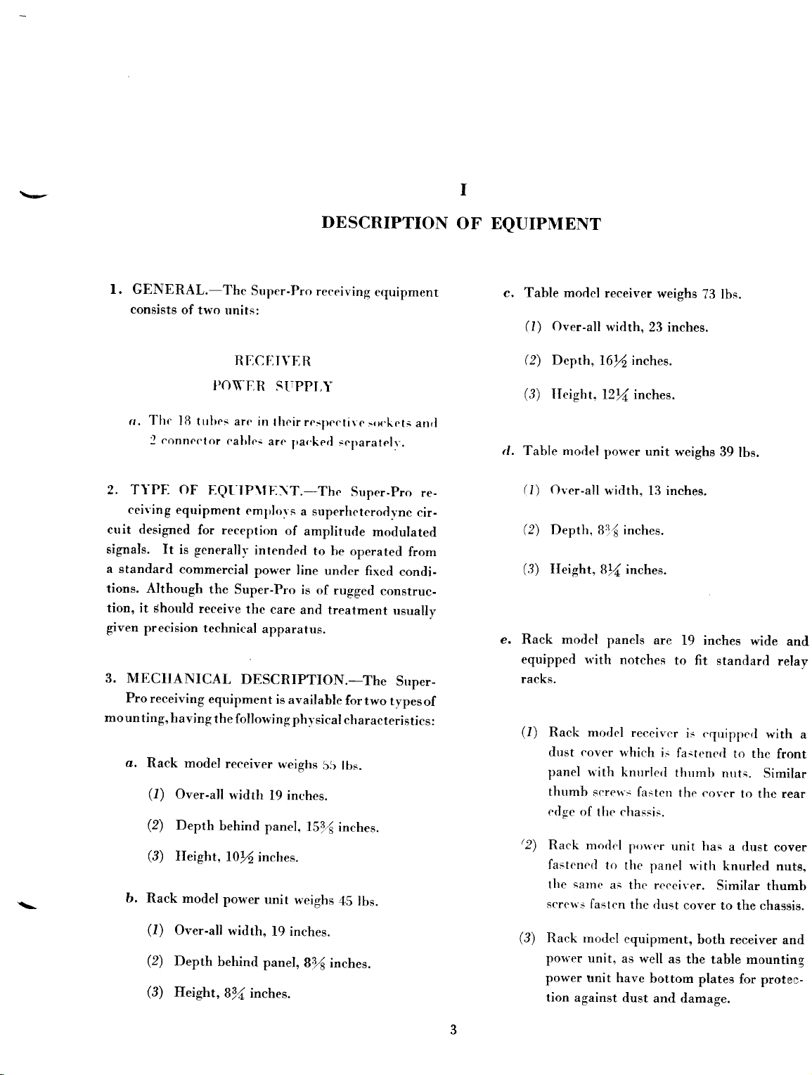
f . GENERAL.-The
consists
of two
units:
})O\rER
Thc
a,
2. TYPE
ceiving
cuit desig"ned
signals. It
a standard
tions. Although
tion, it
given
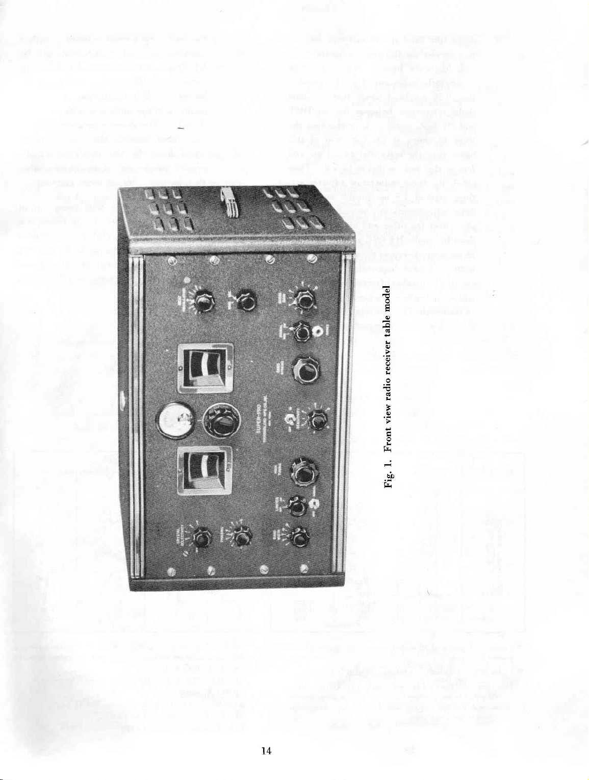
3. MECIIANICAL
Pro
mounting,
a.
b.
ìB
trrbes arc
conneclor
f
OF
EQLIP\ÍE\T.-The
equipment
for reception
is
generallv
commercial
the
should
precision
receiving
receive
technical
equipment
having
Rack model
(l)
Over-all
(2)
Depth
(3)
Ileight,
Rack model
(l)
Over-all
(2)
Depth
(3)
Ileight,
calrlci
the {ollowing
receiver
behind
l0/2
power unit
width,
behintl
Bll inches.
DESCRIPTION
Super-Pro
RIiCI]IVER
in
their rcspcctire
are
emplovs
intended
power line
Super-Pro
the
care
apparatus.
DESCRIPTION.-The
width
lg inches.
panel,
inches.
19 inches.
panel,
receiving
STJPPI,Y
Irar.kerl
of
is
available
phvsical
weighs
t'eighs
sr-Paratelr'.
a
superheterorìt'nc
ampliturìe
to be
under
is
of rugged
and
treatment
55 ltrs.
lSf{
inches.
45
B)( inches.
equipmenr
srx'kcts
Super-Pro
modulated
operated
fixed
for two
characteristics
lbs.
anrl
re-
cir-
from
condi-
construc-
usually
Srrper-
types
of
:
OF EQUIPÙIENT
c. Table model
(l)
Over-all
(2)
Depth,
(3)
IIeight,
d. Table model
(I)
Over-all
(2)
Depth,
(3)
Ileight,
e. Rack modcl
equipped u'ith
racks.
(l)
Rack model
dust cover which
panel uith knurlerl
thtrmb
erìge
of
'2)
Rack modcl
fastened
sarnc
the
screlrs
(3)
Rack rnodel
po\r'er unit,
power
tion
fa,sten
unit have
against
reeeiver
width,
23 inches.
16l$ inches.
l2l{ inches.
power unit
width,
81é
13 inches.
inches.
Br,1 inches.
panels are
notches
receivt--r
scre\rs
fa-sten
clrassis.
lre
I
prxter
to
the panel
as
tl.rc reeeiver.
the
equipment,
as
dust
well
bottom
weighs
73 lbs.
weighs
19 inches
to fit
standard
is equipperl
is
fastcned
thurnb
the cover
unit has
.rrith
Similar thumb
dust
cover
both receiver
as the table
plates for
and damage.
39
lbs.
wide
to the
nuts.
to
a rlust
knurled
to the
mounting
and
relay
with
front
Similar
the rear
cover
nuts,
chassis.
and
protec-
a
(41
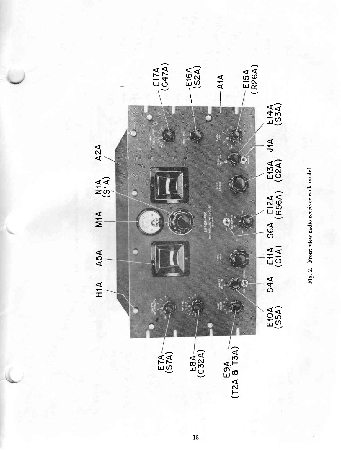
All front
baked
.
All
.f
controls
tified
functions
page 7.
chassis
serve
to connect
antenna
(l)
Power
terminaì
eable
(.2)
The
on
chassis
tìre frrse-holdcr
g.
Terminal
supplies
covers.
eqnipment is
fie.
5).
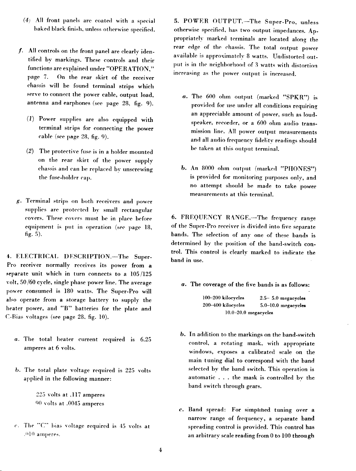
ELECTRICAL
1.
Pro receiver normally
Feparate unit
volt,
50/60 cycle,
power
consumed is
paneìs
black finish,
on
the front
bv markings.
are
explained
On
the
rear
will be
found
the
and
earphones
supplies
strips
(see
page 28, fig.
protecrive
firse is
the rear skirt
and
can
be repìaced
cal).
strips on
are
txrth receivers
protected bv
These c<'rvcrs
pul irt operation
DESCRIPTION.-The
receives
which in turn
single
phase power line. The
lB0 watts.
arc coate(l
power
for connecting
also operate from a storage
heater
power, antl
C-Rias voltages
"8"
(see
page
batteries
28. fig.
u'irh
unless otlrerwise
panel
are clearly
These
under
skirt
terminal
(see
are
controls
"OPERATION,"
of the
strips
cable,
output
page 28, fig.
also
equipped
the
9).
in a holder
of the
power
bv unscrewing
and
small
rectangular
mrrst be
in
place before
(see
its
power
connects
battery
The
for the
Super-Pro
to a 105/125
to supply
plate and
f0).
a special
specified.
iden-
and their
receiver
which
load,
9).
wirll
power
mounted
supply
power
page 18,
Super.
from
a
ayerage
will
the
5. POWER
otherwise
propriatelv
rear edge
available is
is
put
in
increasing
a.
The
OIITPUT.-The
specified,
marked
of the
approximately
the neighhorhood
as the
600 ohrn
providetl
an
appreeiable
speaker,
mission
and all
be
b. An
is
no
line.
audio frequencv
taken
8000 ohm
providerl
attempt
measllrements
6. FRIiQUENCY
of
the
Super-Pro
bands.
determined
The
sclection
by
the
trol. This control
band in
use.
o.
The coverage
100-200 kilocycles
200-400
has
two
terminals
chassis.
power outprrt
output
for
use under
amount of
reeorder,
at this
Aìl
output
or a
power
outpur
for monitoring
should
at this
R,\NGE.-The
receiver
is
of
any one
position of
is clearly
of
five
the
kilocyclee
10.0-20.0
Srrper-Pro,
output
impedances.
are located
The
total ourput
B rvatts.
of
3
watts
Undistorterl
with
is inereased.
(marked
all contlitions
power,
600 ohm
output
fidelity
measurements
rearlings
terminal.
(marked
purposes
be
matle
to
terminal.
frequencl'
divided into
of
these bantlg
the bancl-switch
marked
to intlicate
bands is as
2.5-
5.0 megacyclea
5.0-10.0 megacyclee
megacyclee
unless
Ap-
along
power
out-
distortion
,.SpKR")
requirinq
such
as
loud-
audio
trans-
shoultl
"P[IONES")
only,
and
take
power
ranse
five
separate
con-
the
follows:
the
is
is
a. The
amperes
tr.
The
applied in
c.
Tlre
tl
.t
total lteater current
at 6 volts.
total
plate
voltage
the following
125 volts
Q0
volts
"C"
(J
antlreres.
at
at .0045
Ìrias
.ll7 amperes
voltage
reqrrired
manner:
amperes
requiretl
required
is
is 45
is
6.25
225 volts
volts
at
In
b.
arìdition
control,
rvindows,
main
tuning
selected
bv the
automatic
band switch
Band
c.
narrorr
spread: For
range
spreading control
an arbitrarr-
to the markings
a rotating
exposes
mask"
a calibrated
dial to correspond
band switch.
the mask
through
gears.
simphhed
of
frequency,
is
provided. This control has
scale reading
on
the band-switch
with
appropriate
scale on
with the band
This operation is
is controlled
tuning
a separate band
from 0 to
100 throu
the
bv the
over
gh
a
7.
DIAL
is
calibrated
o.
8.
TUBE
are
ueed
o.
approximatety
quency
from
dialo
how
capacity
as
(l)
covered
that indicated
to
some
far
the
of
the
the
scale
approaches
To
cover
spread
the
it
high
ia
deeired
dial,
band
frequency
CALIBRATION.-The
directly
BAND
l0
mc-20
mc
5 mc-10
100
200
2.5
The
band
kc-200
kc-400
mc-5.0
above
spread
mc
kc
kc
mc
calibration
dial
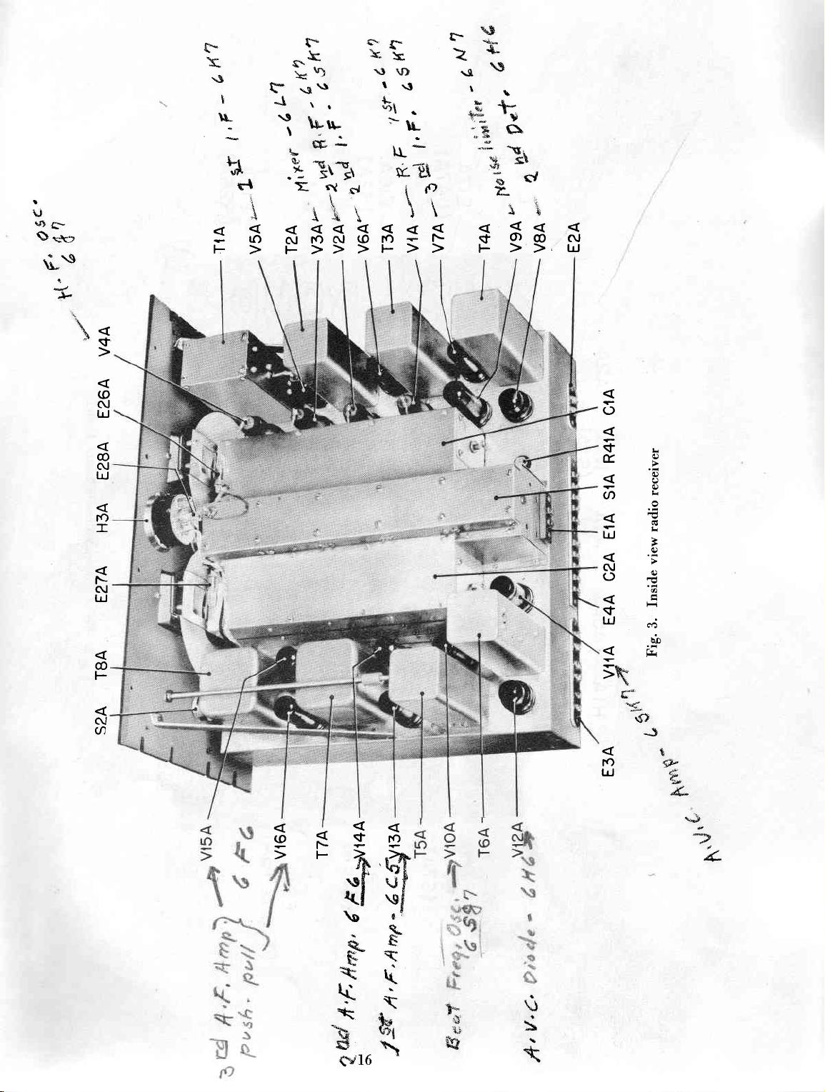
COMPLEMENT.-The
in
the
receiver:
The
TYPE
óK7
óK?
6L7
6J7
6K7
6SK7
6SK7
6H6
óN7
6SJ7
6SK7
6H6
6CS
6F6
2.6F6
following
TYPE
5A
80
FUNCTION
lst
RF
2nd
RF
Mixer..
HF
Oseillator
letIFAmplifier.........
2nd
IF
3rd
IF -{mplifier..
Second
Noise
BF
Oscillator. yl0A
AYC
Amplifier..........
AVC
Diode.
lst
AF
2nd
AF
3rd
AF
tubes
FUNCTION
Plate
Voltage
C-Biae
170'.
lower
band
by
moving
spread
by
spread
ff
set
at
the
the
setting
frequency,
dial
is
condenser
100,
dial
will
o{
depending
movecl.
0.
a specific
the
main
end
range
dial
of
with
ehould
the
band
to spread.
main
tuning
in
frequency
eet
at
ae
CALIBRATION
100
kc per
100
kc
2
kc
5 kc
50 kc
holde
true
100.
followe:
division
per
divieion
per
division
per
divieion
per
divieion
only
foilowing
SYMBOL
Amplifier.
AmpliGer.
Amplifier.
Detector.
Limiter
Amplifier.
Amplifier.
Amplifier........V15A-VI6A
Rectifier
are
used
Rectifier.
. .
. .. . ..
. .....
.......
in
. .
VrA
V2A
VBA
V4A
VsA
VóA
V?A
VBA
V9A
VlrA
Vl2A
Vl3A
Vl4A
the
power
SYMBOL
vlB
v2B
the
fre-
extend
the
main
The
increases
the
band
be
set
which
dial
with
the
tubes
unit.
on
to
SENSITIYITY.-Normally,
9.
more
sensitivity
termining
ground
Regardless
the
background
trical
the
Ievel
very
o.
b. Full
factor
or
external
of
apparatus
or
intensity
difficult
As
a
guide,
tivity
ered
by
benefit
the capabilities
or
to obtain
characteristics
a
Super-Pro
installedo
choice
f0.
SELECTIYITY.-A
available
selective
range
is
cycles.
receiver
a degree
the
beet
interference.
in fig.
12,
a.
Radio
sufficient
(removed
of location.
in
this
point
of
approximately
This
wide
to be
used
of selectivity
possible
Typical
page
30.
Frequency
to reduce
from
the intermediate
b.
fntermediate
variable
filter
16
takes
where
effect.
band
degree
secondary
control
performe
over
out
of
kilocycles.
place
the
Radio
Yariation
width
of coupling
coils
on
the
thia
than
can
actually
in
practical
noise
not
generated
external
or
atmospheric
of
the
noise
desired
satisfactory
fig.
13,
page
typical
can
with
receiver.
of
the
excellent
be obtained
respect
wide
receiver.
the
Starting
crystal
from
range
for
fidetity
of
a great
can
be
with
found
seleetivity
selectivity
images
the
main
frequency)
frequency (465
wide limits.
the
circuit,
Some
deviation
on
the
two
Frequency
of
the
intermediate
is
accomplished
between
of
the
panel
marked
operation.
the
be
operation
of
the
(generated
conditions)
signal,
reception.
31, illustrates
of
the
five
sensitivity
only
to
the
range
filter,
100
cycles
selectivity
many
services.
which
the
leasr
curves
(pre-eelection)
or repeat
freguency
to
a
kc)
Vith
the
range
from
low
frequency
Etages
by varying
the
IF
transformers.
BAND
Super-pro
used.
ie
the
in
the
receiver,
it
bands
when
properly
antenna
of
selectivity
with
the
the
selectivity
to
permite
will
amount
ere
by
minimum.
eelectivity
the
is
from
this
have
frequency
primary
VIDTH
ha
The
de
back
receiver
wher
by
elec,
reacher
becomel
sensi
cov.
of the
and
mosr
16
kilo.
the
Usually
provide
of
shown
is
spots
twice
,
ia
crystal
3 to
figure
bande
some
the
and
The
ie
crystal
The
c.
has a clistinct
filters.
five degrees
settings
(t)
Thc
selectivitv
ratlio telephone
extreme interfercnee, the thirtl
marintelìigibilit-v
removed
frequencies.
(2)
The
reception
selectivity
though telegraph
on any
course,
other signals
made
filter
ernploverl
advantage
Resitles thc
OFF'position.
of selectivitv
control knob
the
of
first tn-o settings
in
tl.re
ovcr
other types
governed
br
on the
of
the cr_vstal filter
Super-Pro
panel.
control are r.speciallv
reception.
be used, thorrgh a good
of
thc
voice
due lo lack of the
In
portion
signal may be
higher
last tl'o degrces of selectivity
of radio telegraph signals
is more important than
signaìs
dcgree
of -selectivity depending,
on the amount
or disturbances
may be received
of interference
of the
varietv.
there
different
suitetl
cases
position
of
the
audio
are for
*'here
quality,
from
man'
of
are
to
of
of
f
l.
AUDIO FIDIìLITY.-There
trolling the
o.
qualitv of reprotluction
f)uring reception the overall
receiver controls
adjrrsted
to a
qualitv u'ill be deepened in
lack
ofhigh audio frequencies. As
is broadened.
the qualitv of response.
high
higher frequencies
the
are two factors
of the
selectivity
degree of selectivitf,
tone due to
stronger.
b. The audio
of the receiver can
part
what has already gone through the IF amplifier. fhe Super-Pro audio
tively
ducing
high
voice
quality
system, capable of
music
or
amplifier
with a good
fidelity.
Fidelit,v
c.
in operation
curves taken with
reproduced
are
the entire receiver
on
page 31,
con-
receiver.
of the
Vhen
the
the
the selectivity
become
only
pass
is a rela-
repro-
degree of
fig. l4'
l. CONNECTING
operating
ment,
temperature
obtaining
perature
bration.
r
ibration
the
In
therc are t$'o
.|eration
f,,r
position
it shoultl
antl
uniform
humiditv
or
the
Vhile
have
will
adjustetì
receiver
addition
rrsc
o.
is
to
connector
r-ith
rtith batteries.
l'acuum tttbes
The
,'t..
These
.-1rt't'tion antl
-rrre
r,'r't'ir
,11,,11p,1 lltr trr,,
all
('r.
lttlrr'.
the
EQUIPN{F,NT.-In
the Super-Pro
for
be borne
humirìit)-
performance.
Super'Prti
some
lhe receiver
polver
îrtbes
adjustment
an,l
in mind that
pla]-
have
will
effect
a
for
cables.
unit. and
are
rvere enrPlovetl
are in tlrr-ir
retttove
glass
INSTRUCTIONS
selecting
receiving
important part
an
\l.ide changes
effect
some
of
solid
is
on
lterformance
degree
high
power
in rhcir
tlrr'
unit
is for
One
the
respe(ltive
tluring
al the
rectifìr'r
factorv.
l)t'()l)cr
<'ardboartl packing
of seìectivitv.
other
sockets
lrrbes
equip-
evenness
in tem'
on cali-
construction'
tubes,
antl
normal
cable is
frnal
\lakc
in the
in
the
in
when
sock'
in-
thc
of
II
FOR
INSTALLATION
Then
polr'cr
pon'er
(l)
(?)
unit'
supplr
Remove
rcceiver
supplv
strips
minal
removing
of thc
rear
terrninal
on thc
strip
will
It
cable
the
on
rvith
sions
and
ceiver
installed
be
FORCE!
USE
prnperlt-.
*'hether
mine
properlv.
the
and
eablc.
strip
be
connect
together
large
attach
The
the
is
a simiìar
power
of
power
noted
correspond
terminal
the
power
without
If
remove
not they
or
certain
Be
as
terrninal
one
cable
one
terminal
rtnit,
calile
the
unit.
the
that
These
unit.
diffrcultv'
thev
antl
the
receiver
thc
follorvs:
cover from
of the power
cntl
having
rcferretl
cover from
attach
to
See
terminal
exactlv
boards
terminals
not go
do
examine
being
are
screws
and
the
ter'
two
After
to.
the
other
the
the terminal
28'
page
strips
dimen'
in
re'
the
on
can
NOT
DO
together
deter-
to
applieil
fully
are
If
b.
the equipment
teries,
ance
cable
having
consists
be the
power
The
c.
to
either
proximately
ventional
is
an
secondary
This
anced
minimum.
(l)
In
the
"4".
used,
unscrewed.
the screws
connections
with the
used
only
same
unit.
antenna
electrostatic
screening,
lead-in,
the case
terminals
drawing
for
one
of free
as for
input
a balanced
ll5
single
of
each
.
of the
feeders
at
If a
single
its
lead-in
Terminal
from
the
is
to
should
in fig.
battery
terminal
wires. All
normal
has
been
transmission
ohms
impedance,
wire
antenna
screen
antenna
together
reduces
transmission
should
the rear
wire
should
lugs
should
top.
See
be operated
be
made in
10,
page 28.
operation
strip,
the other
other
operations
operation
designed
or
and
ground.
bett'een
rr-ith
noise
be
of
the
type
primarr.
input
transformer.
a two-wire
pick-up
line
connected
receiver
of
antenna
be
connected
elip under
page
with
accord-
is
the
with
to couple
lini
of
to
a con-
There
to a
lead-in,
to the
marked
28.
bat-
The
end
will
and
bal-
one
the
ap-
is
to
(2)
(3)
Earphones
d.
propriate
on
testing.
terminal
Next,
e,
the AC
one
of
o'4"
good
For reception
band
signed
connected
grade
efficiency.
It is
chassis
plished by
one
cover
the front
see
the
terminal
ground.
of high
doublet
lead-in
not essential
but this
of
the thumb
to
the rear
should
plug to
pane]
Earphones
strip on
connect
porver
line.
"OPERATION."
"4"
terminals,
should
over
frequencies,
or
similar
to
the receiver
cable,
will result
to
may
connecting
screws
of
be connected
jack
the
(see
may
the rear
the
power cord
For
and
be
connected
a relatively
a
tuned
through
ground
be readily
a ground
securing
the chaseis.
provided
fig.
2) for
also be
connected
skirt of
(see
further
the
othc
to
narror
suitably
in
exceptionr
the receiver
wire
with
preliminary
the chassie
information,
de
antenn
a high
accom
under
the dugr
an ap,
for them
to s
fig.
5) tc
l. PLACII.IG
the
equipment
possible
shipping.
o.
The
ready
oocket
of
(I)
mechanical
tubes
the
It
from
order
IN
OpE
RATTOII.-After
should
defects
for
this
installed
being
tube
is necessary
in
marked
which
the rack
to
make
be
checked
caused
equipment
their
proper
with
belongs
to remove
model
sure
that
ADJUSTMENT
installation,
.thoroughlv
by
handling
are
shipped
sockets-each
the
type
number
in
that
socket.
the
dust
cover
of
the
Super_pro,
all
tubes
are in
for
and
al-
in
III
AND
OPERATION
their
proper
moving
fasten
Similar
of
the chassis
This
dust cover
until
the equipment
ing
satisfactorily.
additional
vicing
(2)
The dust
power unit
jackets
places.
the knurled
the
dust cover
thumb
be
cover
from the
screlr-s
must
operation
required.
must
to remove
This
is done
thurnb
to the front
on
also be
mav
is
found
This will
should
also be taken off
two rectifier
nuts
the rear
removed,
be left removed
to be operat-
avoid an
further ser-
the cardboarJ
tubes.
by re-
which
panel,
edge
the

(3)
Roth dust covers
the equipment
operating
ADJUSTMENT.-This
2.
has
satisfactoril
equipment
pletell adjusted at the factory
ment
should be necessarv
prior to
should be replacetl
been found
v.
has
been com-
ancl no
further
adjust-
actual operation.
after
to be
interference
justed
pending
sired.
is
a wider
to
upon the amount
fn
general,
adjustetl to the
qualitv with
tone
ferenee.
not serious, it
can
dcgree of selectivity,
of fidelity
this eontrol shoultl
banil n'idth
providing
a minimum
be
addede-
be
best
of inter-
3. OPERATION.-Although
technical
of
eontrols, it is relatively
14 controls
used at the
sary for operation
for which
controls
A.
of
piece
apparatus with
easy
on the panel. Ilowever,
same time. The number
*'ill depentl
the receiver is
are:
RAND
SWITCII AT]DIO
T,ÍAIN TLINING
RAND SPREAD
(l)
The remaining
play as
b. Assuming
conditions
that the earphones,
controls
and antenna have been connected
instructions, the various controls
in the following positions:
the Super-Pro is a highly
quite a large
to operate.
thev
of controls
on the
tvpe of service
to be used.
number
There are
not
are
neces.
The maior
GAIN
SENSITIVITY
are brought into
demand
their use.
power
supplv
according
should be
all
to
set
(3)
All
shoulcl
trol
wider band
cult. Rand
tuning,
be done with
set at 3. Other settings provide
or
with
without the meter,
the hantl
making accurate
tuning diffi-
width adjustments
width con-
mad.e after the signal is tuned in properly.
14) The beat-oscillator
SIGNAT,
switch
is turned on when
is in the CW
position. The
heat-oscillator control varies the pitch of
the heterotlr.ne
or beat between
lator and the incoming signal. This feature
is used for code
weak moclulated
(5)
The I,IMITER
limiter on and off.
valuable
on the
automobile
similar disturbances
reception
signals.
control turns the noise
The noise limiter is
higher
ignition interference and other
are serious.
for loeating
and
frequencies where
a
should be
the
the oscil.
most
CRYSTAL SELECTIVITY...
PHASING.
BAND
LINIITER ......OFF
AUDIO
SEND_REC.
(l)
Then throw the
of the panel
position.
WIDTII .. . , . .. .3
AVC NÍANUAL. .. ....
sENSrIrVrTY.........
BAND SPREAD
MOD-CW.
GAIN.
BEAT OSCILLATOR...
switch in
power
(marked
This
puts
OFF-ON
the receiver in opera-
tion.
(
2) The band switch should be
band t'hich the operator
most active. Receiving
band u'ill
himself
band u'idth control
permit the operator
u'ith
the various
should be set at 3. If
, .OFF
.....On arrow
..AVC
.....10
.....100
...MOD
.. ..6
.....REC
....0
the center
the
to
adjusted to the
is likely to find
stations on this
{amiliarize
to
adjustments.
The
ON
So
c.
sary for
tion, the
set in the
TMTY
sensitivitv.
(l)
(2)
far, we
have consitlered adjustments
ratliophone reeeption.
AVC-MANUAL
MANUAL position
control turned
strong signals,
On
be turned
all the
cause overloading.
rìown to
this control should
rvay on because
If the
For code recep-
control should be
antl the SENSI-
,A.IJDIO GAIN
control is set at approximately
can be regulirted
adjustment
Because
of the type
in the Super-Pro,
effectively
The AYC action
have an
ters
effect
ofhigh speed
to control
with the SENSI'IIVITY
only.
of AVC system
signals
code
controlled
with
is slow enough
upon individual
code, but
the
overall
level of the signal.
it is fast
neces-
provitle
proper
it
volume
7,
can be very
this system.
not to
character-
enough
not
will
used

d.
The
operate
first
phone
tion
two
(l)
e.
The
SEND-REC
This
instant
when
ervstal
filter
beeause
three
positions
reeeption
where
interference
positions
After
control
are
rhe
is
adjrrsted
seleetivitv,
rrsed
to reject
t'rthistle.'o
receiver
can
switch
allows
the
service
it is
used
is
verl.
effeetive
of
its
exceìlent
are
generallr-
and
*-ill
serve
is
not
for
code
reeeption
CRYSTAT,
for
the
PII{SI\G
Ìreterotlvne
be
silenced
to
the
receiver
during
for
to
transmission
communication
and
stabilitv.
userl
for
code
serious.
erelusivelv.
SELECTMTY
the
desired
control
interference
bv
turning
SEND
remain
purposes.
easv
The
for
radio-
reeep_
The
desree
may
position.
reatly
periods
to
last
of
be
or
the
for
spread
easv
ú
For
earphone
into
the
panel.
the rear
These
jaek
the
The
S-meter
adjusted
as
a tuning
the receiver
coming
by
the
width
tuning
out
over
tuning.
operation,
jack
provided
A
set
of terminals
of
the chassis
terminals
on
are
the front
eonnecterl
operates
for
AVC.
This
guide. Its
approaches
signal.
lìxact
greatest reading
control
bv
rnust
means of
be
the
the
band
earphones
for
them
are
for
eonneeting
panel.
onlv
when
meter
reading
resonance
resonance
of
the
set
at
meter.
spread
are
on
rhe
also
available
earphone
in parallel
the
reeeiver
is
usetl
will
inerease
with
is
indieate,
meter.
The
3 for
dial
fr
plrrgqe
fror
wit
mainl
the
ir
ban
accrrrat
o
j
a
j.
All
tuning
I\G
control.
dial
is left
so
as
to
óelorr.
is
set.
(l)
The
ouslv
bands
maticallv
on
manner,
can
ar
spread
the
freqrrenev
band
throughout
covered
the
two
be
done
rvith
fn
this
ease,
100.
The
band
out
a narrow
to
sprearì
dial
the
bv
the
disconneeted
low
frequencv
high
frequeney
the
the
spread
band
rr.hich
the
operates
three
high
receiver,
br.
the
bantls.
bands
MAIN
of
TUI\_
bantl
spread
dial
operates
frequencies
main
dial
continu_
frequencv
but
is
auto-
band
switch
In
this
can
be
NTAINTENANCE
IV
AND
(I)
The
more
adjustment
the
s;stance
means
mav
approximately
The
on
an
so
adjusted
change
6 db.
REPAIR
meter
calibration
or less
second
arlritrary.
at
the rear
(letector
in shunt
of
this
a(ljustment,
be obtainerl
l0
normal
input
factory
of .50
each
in
signal
'.S"
in
A
of
diorle
with
the
on
ant
anrl
10,000
adjustment
mir:ro-volts,
"S"
nurnller
input
of
screw
the
varies
an
input
chassis
numbers
meter.
59 reatlin
i
drive
nea
the re
R.
betweer
micro-volts
is
madr
anrl
wher
reJ)resents
:
aJrJrrrrrirnatelr
f.
GENERAL.-The
spected
necessarv
tubes
indicating
justments
and it
tubes be
and
should
is
used
adjusted
over
bc
lo*-
sensitivitr.
u.ere
stronglv
for
receiver
and
long
periods
tested
at regular
shoukl
originallv
recommendetl
replacement
has
servicing
of
operation.
intervals
Ìre
rnatle
rvith
that
purposes.
been
carefullv
is
not
replacetl.
R.C.A.
the
generall\.
Vacuum
and
those
All
tubes
same
tvpe
in-
atl_
a.
If
the receiver
it
mav
condenser
socket
labrrlations
part can
lieve
describecl
bct'orncs
be rlrrc
voltagcs
bc
that rletailcrl
tr)
()l){'n
or
Íìrì
arrrl r.,rrnparing
in
tlrc clrarr
quir.klv
sint'c
most
r',rrnlrlclr,ll
a:[ìr)rt{,rl
r{':ist()r.
llragc
rliscor.cretl.
continuitr-
()t)crators
inoperative,
filtcr
or
br--pass
[lr
rneasuring
thcrn rvith
l3).
thc rlefecrive
\lte
do
not
tests
shoulrl
arc familiar
the
lre-
lrr.
with
ordinary
the
component
tive
power
cover
tom
are
parts
should
resistor
any
locating
gram,
b.
c.
receiver has been accurately
The
factory
should
either sensitivity
to be
pear
checked, it
been
alignment.
cover
tom
adjustments
structions
should
performance
Anv changes
tively
when
cised
true
cially
which should
tuning
main
calibration.
screw
The Test
calibrated
signals
kc and
400
oscillator
of 100
approximatelv
aÌigning
For IF alignment
frequency
Tl're
is e\tremel\
calibration is to be correct.
The Output
cI.
modulation frequency
preferablv
procedure
parts. fn both
supply
be removed
and
retain this
small
driYer
micro-volts and
units,
should be removed
plates
accessible.
from its cabinet.
or capacitor may
the symbol
referring to the
and under
plate
are
be experienced
checking adjustments.
of the fIF Oscillator
Oscillator
covering
should
the RF
normal
adjustment indefinitely.
or selectivity
below normal, and all tubes have
may
Removing
of
accessible. If the
carefully carried out, no difficulty
of the
original settings will be
from
and extreme
I\OT be disturbed unless the
is definitely
dial
not manipulate the insulated
Do
indiscriminatelY.
instrument
frequencies
2.5 and
have an outprlt
100
and
these
calibration of the test oscillator
important,
Meter should respond to the
{00 cps, and should provide
for determining
(rack
mounting)
The
table model
be obtained
number
the receiver will make all
20 mc
ohms {or best results
on the circuit
parts list.
aligned at the
operating conditions
(or
desirable to check the
be
the dust correr and bot-
restoring
in
receiver.
should
producing
an output
HF Oscillator circuits.
values are not critical.
of the test oscillator,
CALITION:-
care should be exer-
circuits
known to be off
be an accurately
between
(also
465
if
the
defec-
receiver
following in-
the
This is espe-
of
impedance of
receiver dial
and
the bot.
so that all
receiver
Values of
by
dia-
Vhen
both) ap-
original
rela-
(fig.
l1)
modulated
100 and
kc). This
the order
when
at
least half-scale deflection for l0 volts.
greater
sistance should
e. An insulated screw driver
thick at bit, is required for aligning
2. PRELIÀíINARY
OFF-ON switch to the ON position and allow
receiver to warm
beginning
the SPKR terminals
to
receiver chassis.
IF-AVC-BEAT OSC.
3.
the
neet the output
tector
panel
adjustments. Connect the output meter
test oscillator to approximately
(6L7)
tube
controls should
SENSITMTY.
AVC_MANUAL....,
N{OD
SEND_REC.
RAND SWITCH
AUDIO GAIN.
CRYSTAL
CRYSTAL
BAND WIDTII
BAND SPREAD
o. IF
ALIGNMEI\T
dial should
ing
should
local signal.
the
manner.
switch
AVC, and
Turn
and adjust
imum
The
in this
particular
be taken
proper
on 3, the
off the
deflection
adjustment
manner
agreement
exact
checked.
modulation
the
tuning
until
CRYSTA'L
of the
the
be
PROCEDURE.-Throw
up approximately
located at the rear
control
to the
through
be set
CW.
SELECTIVITY.
PHASING.
be set
to avoid
Now tune the
alignment
Set the
advance
quartz
After
alignment
CRYSTAL
modulation
frequencv
its
of the
of
is necessary
with
crystal
reducing SENSITIVITY
may
osciìlator
test
SELECTIVITY
than
500 ohms.
9
wide and
164"
one hour
ALIGNMENT.-Adjust
465
cap of the lst de-
grid
fixed condenser. Front
a
as follows:
. . . . . . . . . . . . .
. ......,3
DIAL........IOO
CHECK.-The
near
frequency
AVC-MANUAL
the SEI\SITIYITY
"S"
the test
the
be switched
check
. .0
...MANUAL
.....MOD
...,REC
.......2.5-5.0
........I0
. . . .OFF
2.5 mc, but
tuning
test
in the
SELECTMTY
of the
slightly
meter
oscillator
in order
natural period
in the
must
completed.
is
fts
.025"
the receiver.
before
of the
kc
and con-
mc
.(Jn arrow
main tun-
in a powerful
oscillator
following
switch
to 10.
oscillator
test
until
is obtained.
frequency
insure
to
receiver
but
on,
be altered
not
and
re-
the
the
care
to
on
max'
of the
being
to
the
The
AYC'
0
t0

MANUAL
their original
respectively
til a suitable
A
half-scale reading
5 or 10
b. Now check
antl lower
transformers
trimmer in
meter. If
results in
SENSITMTY
reading
plate circuit
tested in
loroer adjusting
This
screw varies
iron core
eetting
trrnes
the
properly
This
circuit
by
the
modulated
graph.
AVC ALIGNI{IINT
c.
other
controls as aboveo
the test
GAIN
SENSITIVITY
GAIN
meter
T6A for minimum
"S"
meter reading
time the output meter
BF
d.
OSCILLATOR
Continuing with
Alignment)
lator
leaving
connect
headphones,
loud speaker.
and
see that BEAT
exactl,v
controls
and SENSITIYITY
volts
the
(plate)
T4A for
one or
a material
back to half-scale.
of
the same
in coil
of the
grid coil
adjusted
mayo
"visual"
oscillator
oscillator frequencl-,
0, s*'itch
to
to restore half-scale
and
adjust single trimmer
switch off
it tuned
output
or replace
Throw
on zero.
may
now
settings
output
will be
alignment
T2A
screw on
upper
method
of
OFF
meter
reading
in
the
satisfactorv.
of
air trimmer
and
T3A
peak reading
more clf
increase
sufficiently
the crystal
fashion
the
L26A.
L27 A,
b.r the foregoing
however,
these
Alignment
filter
the
position of
f)o
adjtsting
as this circuit
be correctly
employing
and cathode
CHECK.-Leaving
and, uithout
to AVC,
to i0. Increase
reading
output meter
should
ALIGNMENT
controls
meter
If
o'peak"
reading
as
modulation
to same
and
plug
meter
SIGNAL
OSCILLATOR
tone in
be returned
and MANUAL
advanced
is
secured.
neighborhood
both
condensers
and
of
of output
to
bring meter
TIA
by means
side of
the
not
screw
a frequency-
reduce
and increaee
condenser
reading.
at
"dips."
CHECK.
above
of
frequency.
in a
with
switoh
headphones (or
(grid)
upper
in
the
single
the output
adjustments
reduce
of
can
of
the unit.
powdered
disturb
which
cannot
method.
aligned
rav
oscillo-
tlisturbing
AUDIO
AUDIO
on output
The
the same
(AVC
test oscil-
Dis-
pair
suitable
to CW
knob
un-
IF
the
the
the
be
all
in
of
is
to
of
be
epeaker)
trimmer
until such
perfect
sound will
the BFO
quency
audible difference
This
the
ofr 0 toward one side
movement results in an audible tone
pitch
either
IIF
e.
-The
depends
which
higher
when
the
10.,165
oscillator
frequency
is
far
ol known
readings.
at 100
frequencv
(-l)
is not very
condenser
is the case.
alignment
be heard since the test
will be oscillating
and consequently
condition
BEAT OSCILLATOR
as
the pointer is turned away
aide, the BFO is
OSCIT,I,ATOR
accuraey
solelr- on
in
the Super-Pro
than the
the
receiver
frequency
mc.
Vhile
can
bc
measuring
simpler
v'hen
When
calibration
correction, this mav be aceomplished
follows: Reference
(fig.
oscillator adjustments
frequencies at
made. If tÌre 2..5
corrected thc test osr-'illator rnal be
ratelv
monic
5.0 mc end of the band. The output
the test oscillator shoultl be
and the SIG\{L srvitch on the receiver
turned to CS-. The BEAT OSCILLATOR
control
at 10, the AVC-MANUAL switch on
MANIUAL,
to check
frequency
Be
sure
making
bands.
it has been tletermined
1t) rvill show
set to
(if
should be at 0, the
low in
near
when this test
or
may
be determined
CALIRRATION
of
the main
the
signal
is
tuned
of
the IIF
the
measured
equipment
and noting
the
this
is
sufficiendy
which
2.5 mc
strong enough) used for the
and the
pitch,
the
fn case
there
"beat"
frequency.
to 5.0
note
control knob
or
the
perfectly
HF
oscillator
is 465
to a
oscillator
frequency
directly
it
by
band
spread
test
in
in
to the alignment char.
location
the
rrell
as
the settings should bt
mc band is
and its second
BAND
readjust
bottom
at
other. ff
dial
is
tuning
the
error to requirr
AUDIO GAIN
of
BFO
the
is
made,
oscillator
the same fr(
will be n
to be heart
by
turnin
slightl
rising
from 0 o
aligned.
CHECX
calibratio
frequenc.'
(the
kc
For
examplr
10.0
mc
must
of
the
if
accurat
available,
in
signal
the
main
dial
three
that the dia
of the
as the signa
unmodulated
WIDTH at
tl
T5
is
an
suc
II
sign;
b
H
dia
is
ee
high
ar
IItr
bt
to
accu.
har.
o1
i
n
i
i
l1

16.
nected
used
bv the
Iator
lerminals
(2)
Tune
end
approximate
main
bration
high pitch.
enough
audibilitl-.
adjust
IIF OSC-5.0
again
still
make
condenser
this process
bring
obvious
is
once
at
turned
beat
method
Then
the
rect
using
designated
the
the
that
2.5
viouslv
normal,
dial
It
forth
order
into
queIrc\',
During
3t
L,r
TIVITY
output
The
antl
make
to
"zero
should
for this
in the
of the
dial slightlv
line until
to
With the
the
reduced
further
a further
to
dial
the
that
on cxactlv
enough
without
describccl
tune
{requencv
low
calibration
the
inductancc
the
second
end
other
adjustment
the
has disturbed
mc
made
as
affects
aìso
therefore
is
several
bring
to
eract
the
to properlY
taken
control
meter should
heatlphones
necessarv
the
method.
beat"
connected
be
test.
second
dial to
raisc
trimmer
as
in
IIF
harmonic
an adjustment
agreement
above process
harmonic
error.
dial
tot'ard
the
not turn
Do
the
mc until
zero.
to
to*-artl
adjustment
return
manY
exactlv
to
main
the
5.0
one time
at
further
above
2.5 mc
the
end of
OSC'2.5
of the
at 5.0
the
necessarY
timcs
both
to avoid
zero
beat
beat
alignment
conclenser
Turn
the
zero beat.
to
timcs
mc and
acloo
step-bv'step
trimming
is again
dial,
of
tlre
mc.
other
from
ends
with
adjust
be discon-
loud speaker
or
adjustments
test oscil-
The
to the
beat,
Then
the 5.0
the
5.0
5.0
dial
to
the
is
fundamental
the dial
mc
it will
the
This is perfectlv
at one
end
to go
2.5 to 5.0
of the
great
antenna
5.0
the
at
noting
turn
mc
rises to
note
dial
the
beyond
note
clriver
scre*-
designated
note
beat
main
the
line
mc
the trimmer
of
Repeat
necessary
as
While it
mc.
be set
could
the trimmer
produce
step'b)-'step
recommended.
and
as before
adjustment
fig. 11. When
in
tuned
be found
inductance
correction
end
of the
back
dial
signal
the
should
care
the SENSI'
overloading
mc
the
the
cali'
far
dial
and
to
zero
at
cor'
in at
pre-
of the
band.
and
mc
scale
fre-
at
is
in
or
"freak"
reception
due to
excessive signal
input.
lst DETECTOR
Af,ID
RF
.f.
Although
(lst
simultaneouslv
simpler
Efficient
ceiver
ratios
a
three
u'ithout
as these
frequency
oscillator,
(l)
(2)
the alignment
and
2nd RF
antl
with
consider
to
signal
n'eak
level
noise
the
regard
circuits
on
with
calibration
to
are
depends
circuits
465 kc
optimum
required
is
the
to
100
output
the
test
controls
calibration
of
not strictlv
antenna
o,qcillator
Accurate
is not
Modulation
venient,
put
through
ing
If tlrt
ceiver
alignment-if
OSCILLATOR
throrv
and
SENSITMTY
haìf-scale
a
duce
signals
whcn
Starting
the
at
test
output
the
in the
fig.
indicated
same
settings
output
should
reading
ment
make
t'ith
dial
main
antl
100)
oscillatnr
meter.
trimmer
center
Repeat
11.
row.
results
meter
be
to
check
sure
as
If
slightly
half-scale.
the
them
and
relatíue
respect
adjusted
lower
results
to
the
ohms
resistance
should
unmoclulated,
knob
SIGNAL
should
are
the
at
adjust
for
Then
marked
row
this
2nd
readjustment
reading,
the
test
ALIGNMENT'-
three
these
of
1st Det)
the
as
reception
can be
HF oscillator'
separate
operations.
with
image
high
rejection
alignment
IIF oscillator,
to the
accuracv.
resonate
to
of
that
than
be obtained.
will
oscillator
of the
check these
oscillator,
test
adjustments.
while
necessarY.
terminals
should
(approximatc) includ-
oscillator.
of the
modulated
is
as
set
bc
set
(on
cither side)
2
to
switch
adjusted
be
mc
the
peak
on
in tune.
5.0
(bantl
frequencv
tleflection
reading
exactlv
2.5 to
5.0
check
lst DIIT
of acljustments
procedure
and
RF
material
in a
the
altered
After
signal
of
is still
tuning
to
output
band,
mc
spreatl
setting
the
and
shown
on trimmers
RF
lst
one
of
increase
SFìNSITIVITY
reduce
to
each
receiver
the
accurately
circuits
checked
it is
re-
low
these
of
As long
at a
HF
the
con-
in-
The
be
re-
the
IF
for
BEAT
CW.
pro'
to
meter
set
dial
the
of
the
of
of
mc
5'0
in
the
in
these
of
in
the
adjust-
to
L2

(the
tuned
as a vernier for
high frequencv
is
extremelr. important
10-20
the
slight
bantl
mc band
interaction
spread dial
this
bands).
bet*'een
and HF OSC circuits.
three trimmers
at the high
band, turn the main
retune the
check the
tings marked
Since adjustments
also affect
described under
be necessary
until
cured.
t'iìl
depend on holr'
to start u'ith.
checked in
test oscillator
three inductance
2.5 mc
at one
the other
IIF
OSC alignment,
to repeat
no further improvement
The number of repetitions
much mi-stuning
The remaining
the same manner.
mar
purpose in the
This precaution
at the high
where
After
there is
the
lst
checking
end
dial
to 2.5 mc
to
suit. Then
adjuster
in
the same row.
end
of a band
end of
the above
the band,
procedure
can
necessarv
bands mBv
be used
thrce
end of
some
DET
the
of this
and
Eet-
as
it will
be
se-
existed
be
(J)
For
maximum
particular
RF circuits
connecting
loosely
oscillator
directly
a 100
ohm resistor.
signal
reacheo
than
bv some
(a)
In all
meter
readings
recommended
be used
false adjustments
ous responseso
avoided.
possible
antenna
may
be
it.
This can
coupling
to the
to
from
antenna
the
antenna
the test
the
the receiver
form
the foregoing
for
circuit
that headphones (or
to monitor
the signal. In
due
or other
efficiency
arrangement,
adjusted
be
output
without
accomplished
of
Eystem
instead
terminals
N{ake
sure
oscillator
via
the antenna
of
direct
coupling.
tests
using
adjustment,
to overloading,
"freaks"
with
the
lst
dis-
by
the
test
of
through
that
the
actually
rather
output
it
speaker)
this
way
spuri-
may
be
a
is
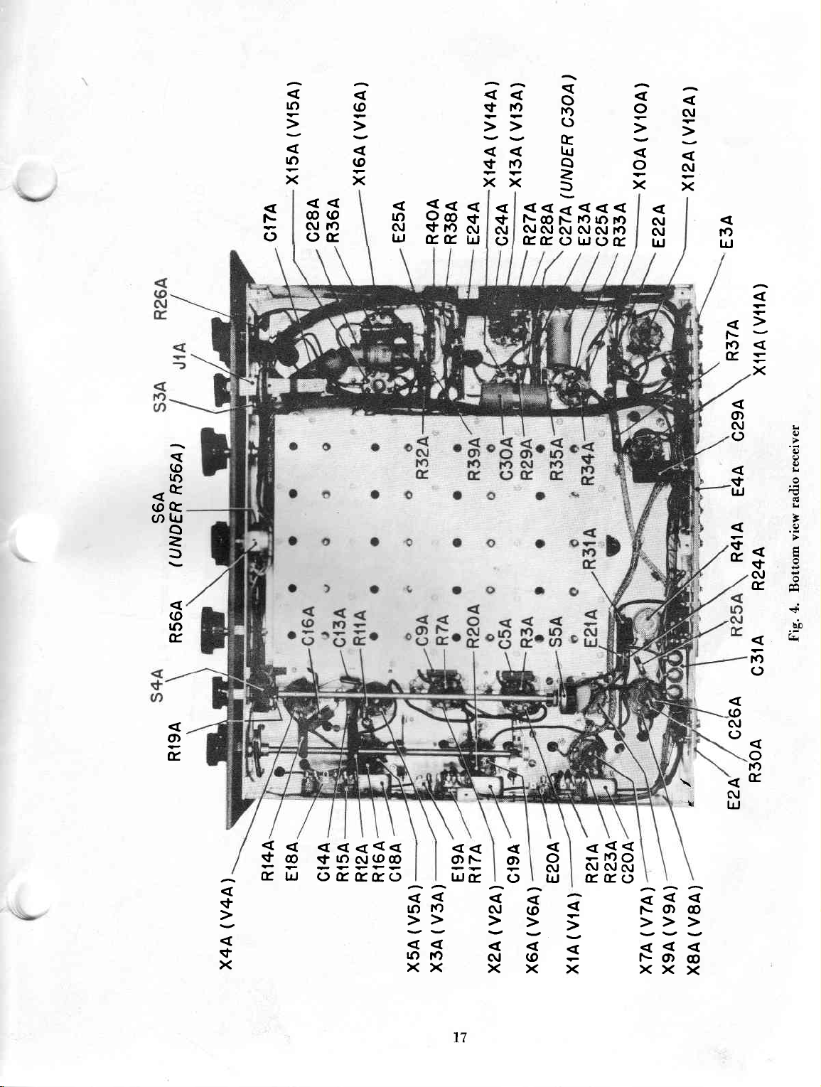
Socket No. Tube
XlA
x2A
X3A
x4A
X5A
x6A
x7A
XBA
X9A
XIOA
XIIA
X12A
XT3A
xt4A
X]54
XI6A
*
Terminals
respect
t*
Varies
The
exacdy equal
higher
variatione
I
to
chassis.
widely with
above
voltage
or lower
in theee
and 2 of all
to
V]A
v2A
V3A
v4A
v5A
V6A
\'74
VBA
V9A
vr0A
vrlA
VT2A
VI3A
VI4A
\-l5A
\,164
different
readings
the
primary
line
voltage
readings.
No.
sockets
tubes;
are
tap on
should
based
TUBE
+250
+250
+250
+150+*
+2s0
0
0
+.4
0
0
-t.L
l0
+l
+2.10
+380
+380
are at zero
also *'ith dial
on an AC
the power
result
in
SOCKET
VOLTS AT
+135
+r3s
+lls
Ì
50*+
+
+135
-43
-1.5
+.4
0
J
2
+240
+s80
+380
Dotenlial s'ith
setting.
line
voltage
transformercorresponding
YOLTAGES
SOCKET
All
resistance
socket
SENSITIVITY
l\fOD-CV'sHitch
AVC-lf ANUAL
SEND-REC
LINf
TERNIINAL
DC readings
of
1000 ohrns
lerminaìs and chasrrs.
sx'itch
ITER
s*.itch
+r35
+135
+r35
+r00
+.4
+40
+rr0
-3.2
are
baserl on thc
and -{['l)lO
slroulì
snitch
should
shoultl
NU]!fBER*
6.34C
6.34C
6.34C
ó.34C
6,34C
6.3AC
6 .3A.(i
ó 3\Ci
1 0..\( l
6.3{(l
fi 3{(l
6 3\(l
6 3.\(i
ó 3\(l
6 3{(l
6 3,\(l
per volt,
lie on
should
be on REC.
be ON.
u,qe. of a rneter having
and are taken between
G-{I\ should be ser at 0.
CW.
on
be
MANUAL.
0
0
U
IJ
+250
+240
|4.
-1_
r))
+240
-3.2
0
0
+38
+38
a
t3
d
o
L
t
3
hD
t4
N
z.a
h
IJ
î-
t
()
ó3
to
kJ
(o
N
(r
joT
ra
vro
ilg:
f
?
::N
|'r
s)
&
L
SE
lrJ
61
!r
1r)
-
lrl
È-
f\
@
@
kJ
c\l
îo
()
ro
{,F
flo
c\,
F.
(o
a
fa
lrJo
\r
a
lv,
lf)
tlrg
tr
F
q)
k
Òl
15
u
irl
C*
$ qqcr
\L.g
.J*'
\<
"$
@
N
UJ
\5
I
\
h
rl
i
ff;
F
!
*r
ì
t* \s\!
+
\r
*,
luu
ÈÉ'*
t
irl',
.L
E
À[\
ìr
\)
r
b,..
r.{
s,t
\\l
È999P
\t)
\S
-t
1.*
o-u
\
]
ìa
fc,
\
\s
|
t}.\
.l
*.
\3
\
*l
È-
s
*no
'l
-1
b
o
@
N
trJ
ro
T
r.-
N
LJ
O
F
N
a
+rr
(Y
ari
IJ:
N..
()È
t
tdm
q)
o
;:
t
'a
Èb
fE
>E'
L
\4ú
\14
fO
UJ
sl'
I
ft-
F
îo
#-
"S
",i,
,ú
\*'
e
ar
$f,
rl
\of
.s.
{
Fq*
rÈ(
s+
ht
\
s\
u3l
d\d16
t?
&
'dt
>
q
<t
(o
K)
<q
@G
gr1
trJ
o
z
f,
@
tf)
É.
F
rJ
lo
to
x
@(o
GJ
TO
ofr
@
@
x
$
Ltl
$f;
$
1g fts 'J
ro
\t
\t
îa
XX
$
AJ
()
o
îf)
()
t
tU
o
=
I
<<d
F
C\J
frfr()uJ()fE
@ r\-
C\I
N
îo
AJ
ro
ÀI Í)
!1,
o
o
x
(\I
(\l
LrJ
AI
C\T
x
ro
lrl
tf)
É,
x
O)
N
()
0.)
$
lrJ
+
É.
r8
c\t
È
É.ù
<|
Èb
++ Cr
îo
o
O)
É.
-(o
C\,
()
o
to
\
'ri
l<
V
@
F
-
fr
uJ
s
t
x
lO
sf,
AJ@@
- --?
F
(J(rfr(r()
îo
rf)
ì>-
rf)
tf,
xx
o
lrJ
17
î--
E
O)
()
*a
N
(\J
és
x
xx
o
C\I
lrJ
*fiÉ
frfro
AAA
l\O)C)
Yvv
F-Orc)
XXX
N
uJ
É.

CD
ra
(D
C\J
rd
\
tr\
"l\
-fD
q)
>.
a
lr
!
3
o6
d- .-
rd5
m
=
to
lrJ
Uî
èo
1B
V,
fD
(\J
:E
(D
C\J
|rJ
&
>'
ó
lr
!
v
oa
Sr
aÍ)
"Îo
d|rJ
3
u.D
19
c2B
:
crB
L2B
RIB-I
R2B
ry,
,w
E4B
(FlB)
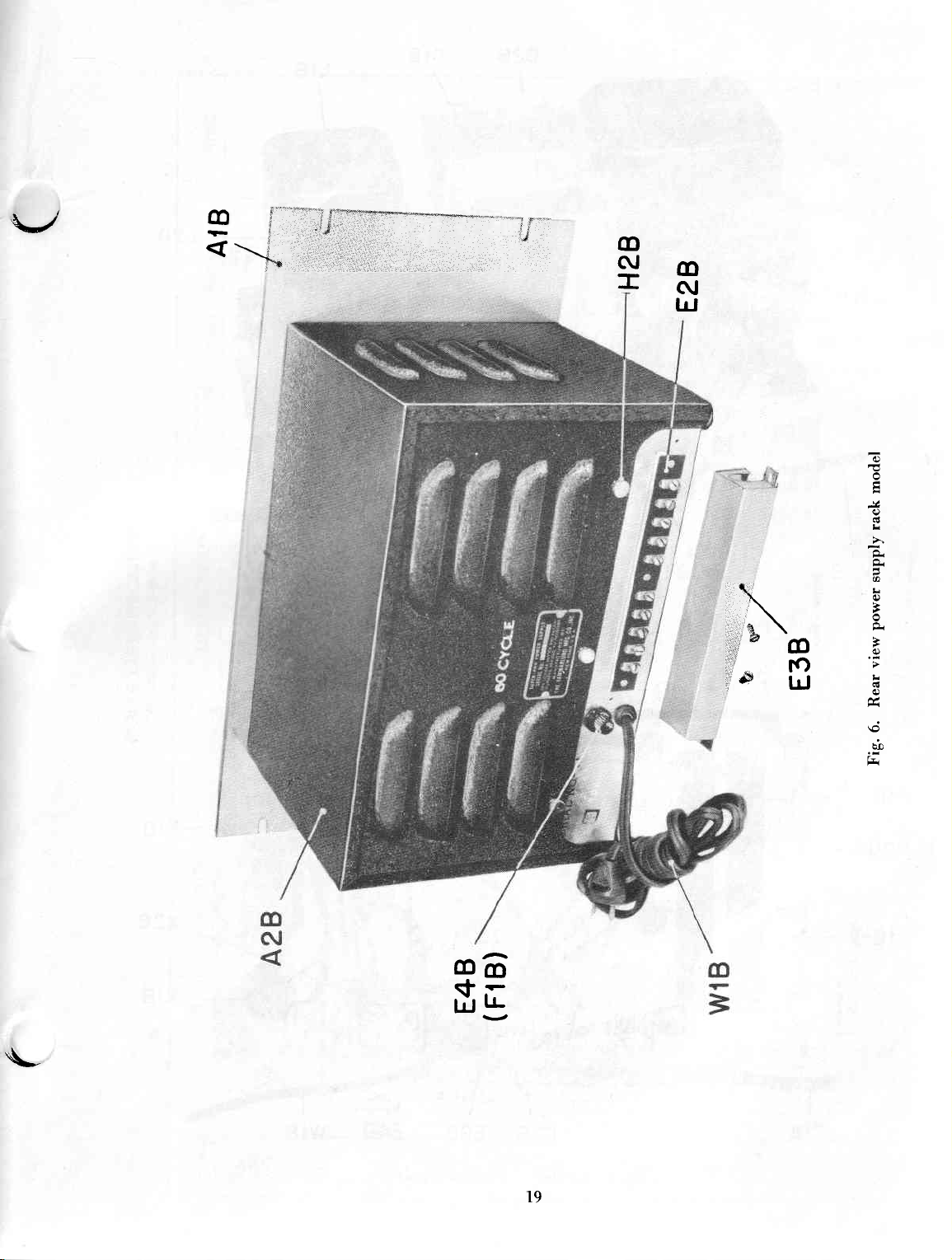
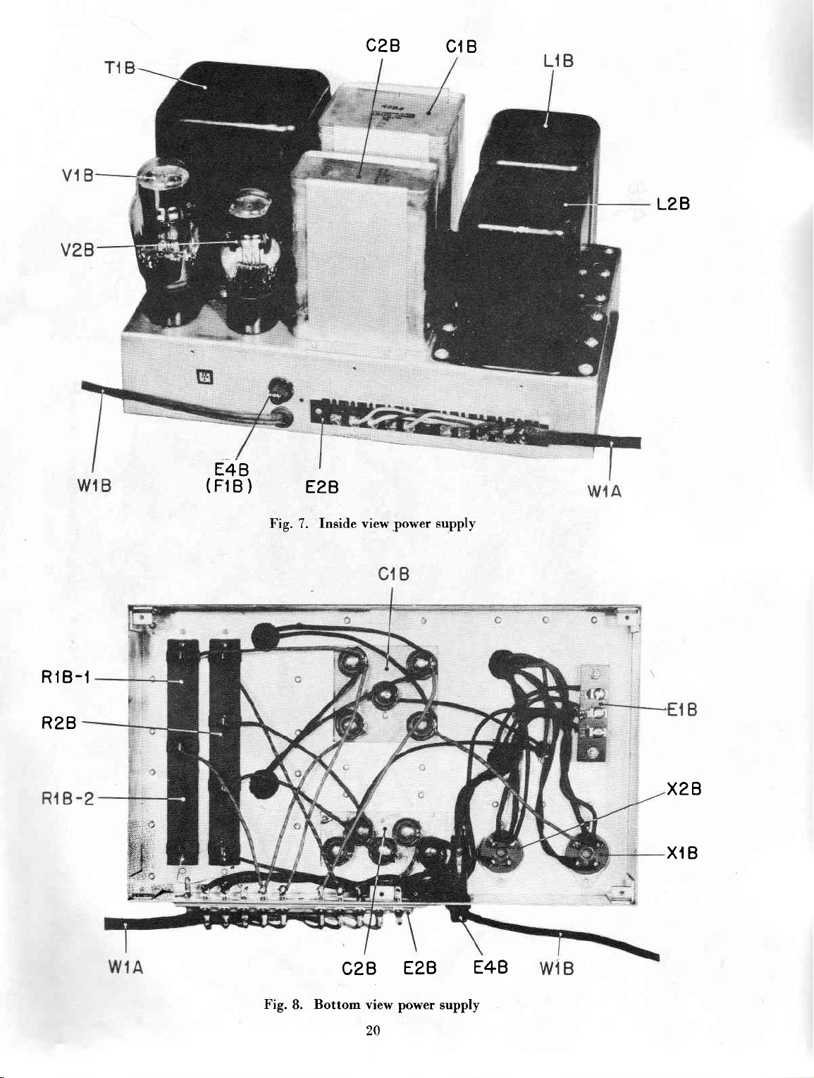
Fig. 7.
E2B
Inside view,power
supply
X2B
X{B
Fig.
B. Bottom view
CzB
20
EzB
power supply
E4B

an
frì
F
z
.or
9
I
I
.s
E
àz
É6
z
^
trì
>:
-E
U+
lrl
É6i
.l
\
F6
Ao
ìi
U)Y
FI
Ft
ú
O
v)
r-l
;
ì
co
9S
66ì
co
6ì
X
ró
o\ o\
ilrNNf\O
r,óNS\ON
{tE IE
Ét; F
.-
-lti-le.Ij
{,++ii
È';i:i::
\-iiÚi Ii
1\?=ie :-
AFEFF
*riEE
'ttÈt
:"j:-:::j:
:EFCÈqFe
\o
o\
ТмИтм
rr1
6l)
O\ O
.E
k-
rbgq
Es
'='i
5:
E
o
Ea
6
'É
E':.
!È
E-*
i.E ;
:i
iL
::
;F
;r
Ey
o-
*:È
Éi
'i.='
.?L
!:
ST =G
.Eg
Ei ;i
ú-
s
>3
.nFr
m
F- CO
\os
.!*
E:
.
r:
Tc
;-j^<.
:iÙ:.TùÙ-3JÉ]-318'
Eir*3**É*r=*tsi.i
=e2ti2'=2t'==ii:iH
==;;
i; A;;;,^:^
&
ua
rO
XX
x>\
Lr,
\o
\o
\ll 1.Ò
lJ1
f-
O\
\O
ssEi
'=
i !
È :
d
O\ O\
\O
Srú
rg
6=
q
i:
'=
Fé
; Eq
q=
=.E
Ù .=
ìn
x
C
3
2
:
ts>
YY>
Lórn
X Xrn
x>.
Fi
\o\o róú\o
0\61 SíAO\
rF-
O\O\O.
iH
COCO-
\o\o
<1 s\o €
€6
-??
: PÈ
':
gg
rH
tr
€llt'î
!ìi:È
q (tr
!, :',t
;È
€€g
--E x
.9*':'iT è
Èifi
É
-
E É E *==* H;
d
+ttÉe
E-rvÈ
-:-.:v
1=óqq3d?
a
Fi
Éi
È
C-
.e
r
o
€
^
g
!
z
aì
F
U
z
-)
À
z
U)
E[
E;
a\ 9a
i^ji
ÈjE:
:T:à
,+iÉ;'
gÈiÈ
i
;:iÉi
iEi
-E :
LLLLLLLLLLLLLLLLLLLLLLLLLLLLLLLLLLLLLLLLLLLLLLLLLLLLLLLLLLLLLLLLLL.ei..s ;.-.rr..: É.=ir--:X.a.a.=.:.i.:.;.:.È.:.;.:.=.:.:.:;
;;
iÈj
É À 3 f É
É6lco<r4 È
'î
5
,'È
-.a
1,
f*
5;È;tE;rÉt"r:t!FFF;!!!!=;;
g*,:i;É*Ji*
i;dA:
5:
î
I
-*
: =: ='=''
i
; *-ofrt.!t*,tiYtE;Ee
F
- .ligg5iàgiffiàifitr
í:sfif;=iifl=tiÉiÈij::
IE"AI E ! i i E ! i
:
F
Èòld:<l
;.i!
!
=
:
dòld)s
^l cn-irn,orcoo\-
A UA(JJUAUUUUUAQUUU
^e^
:iEÈS!ElA
-5
"..)
y
.f
l.l.f
iI=iaili?:l l::
.=p?!=!rijqii"F:"
rssjftÉ55
ósósss33ss333s3s!
2L
îe?
'È
F
a.ho
#5
.i.
='1':
poo
í i
.E
_
5E
p
I
.E
!
!
--
--'.
^lall
fpÉ
F'ii
é5F
ú"
i
:=::rtriÈî
ii!.==Éqh
*É*
;;i
IÈE
Éa i5
=':
k k H'k k:'kA E+'c*î-*'c-+i'-'c'6'6
iiÉ11;
e
s ! ó!
Éòtm
Er?,,,i:i;iEtr
iii
==È
j==i:
--._
rC\|Í)
i;l??ii::îi
Èorúrii.i.ìó.h
:îr't
E F
ff ; !
O
6.t
U OUOUOUOO
if iÉa b 5 d
____r_
ffffósss
ÈGlfO
Èc{(nr+ú\Ol'-CO
N6ì6.1òtC.lòlG.I6{
6'6'6'6

a
E-i
z
.ì
U
tl
>R
H'r
IJN
,a. =
t9
a?
î+
a7.
F
.é
àz
z
F
U
a
I
È o\
q
l- +T
,=
rc)
<\o
a
=<
=
;
-
-aaa
g.
ro
o'-
-.
I
f
o6
ó::ée*:
'oZZ9"'"'.î)
:;
àà
òìc{elNo\o\o\
n+.ncco.m9
<oomNÈ-Ì 6
COOO\COcCaOzi
cr:<,d,c4NNUò
g
,À
\c
cC
m
6t
'z
ú
38.É
?ÉE
6
= i:'î!
=
:E
,
-
=
.:
!
j
i3
--:
**.i
c a;; r:
==i
,í,: ^r
rn!
'=
àE
:'!
?+
ET
=E
;;
.=.EE
;
!
Ì =+.
E.:'
E::3 ". i'i::
j
#s
;i'ai;i
=;=5i=:::-"=:=
. îr,<.<.(n(nc,(n6c,th(h-=o-n^,j,,Í,- dr5';d
iSgSgi5s55
,--='
o E= o o o o ! r o g or= o. J
* * EÌ
g
H T?'..
=
'!
+
!
-
,
Èf
- =- ;iií::,
i;=lriis:=i
: r+i',o-t^
*
=;i:=
t7 t''"t'
I=: I:
==*====
I
=rqi?-:.'
;È:
-
.=.=EiEiZ
i3-====
*
ìì;;II;
iitiii=,;iÍiÍ
" ti4.+i*:?i
-f
i
s
=i=.;l
i
*tt=:
-t444==
i i i
i
)l
: I
;=,=ii=i
o t L+ !. ' ' ! '=
= = =:=
=
+: *'.
-i.,i=-î..5-î.
a
y
.
r
!.
:.:+
= = = = =4=-=
f.-i. i n i,.î.
' !
5
?
e
-.
z
'
2 1Àn-!'^^7
+
Fi
U
ÈE
z
p
; i
t-r
;É
.==
=.
É,
i;
;;
z
<-
j
ii;!i;ii:EiiÉEE
!
---'
ll.S:OÉ
'-.--i
j j
n;-
't
^€€
E*Ía
- lÍ
;::=!Î!::e-=€€si!-ÈÉ==îo.--
€;€!€€:€€y€;;;:.;;;
Íjf íypí;*=-*i€Éri+;t;{!!!5
j-E
ii
-+1ì-:-:=:=:
;r--,-=isèIgc.dEèÈ!EjjÉjj;
**:ÈE:I
ii;;=JJJJ;1iJ".:
-.
VFi EJ---.:
?ì i'b: ì-f
8ÚÚ
i !'F
:---
.
i:!
E:-.-giggiS_i!
i
^
c9_l_.f_.!_q-c!-cf eoAlll
:UUUUUOOUUUUJUUUUJUU-JUUU(J
-N
-
n d +
idilщti-hiiif3s;isif+Й]lщоъъщоt^6
a?E=5
ii.i=.*::.d=
i
iÚ
aì.i à Àrz
! c r i..
új o r co
!?T
afa- ?.-,
È:ÈÉ3FÉ
rs{srÉfrÉtÉ?iÉ?sÉ
i-ài€c^
i{É={*=:=
lE;;:E
r':",1!!!!1.É"Eil7
-
i---
I'd":T
à.i.i
iE!EEdEEdEEsgd!si
! ! ! !
o o
'-.
! 3 3 19i11! ! 3-"_t
-
cQ
ot
!
==:=l=_*l:e,=
zttlt=
-. -. -. -.U:J_UU'-.
:
3 3 i E !;>>r;>
- cc = - i
? ! ' i ' !;
a i I i r i I i
r
q
î:
4 I
l€ l€*É
<<
i i i i i = - = =
q
c-l
ó
€
-
,,
o.i.o.t
i I L ! a.
O !'
LQ
q
^ir
a.=!
:t
! i il
'.i:.
iF
"
*
i
E,
-.=-.=:i:r<.=-p..
=4'sz::==
:i s
l;;;3;
3i:
if
j
^. :
.:'.ii.r::
1?îîÈÈit:tlt:i::i
! !: i trr,2iiiz_i
r
I r r
FF.FFOUUUOUUUJUUUU
<
i6ìcó<tó\orcco\È
3 3 a a a a a e a a 3
< < < I 3 I
I :<
r
i
.E
;$*;
1É=È"
i i
iÉ3i!gilFiis
i .{ i
. .i;
à
:!
,É
iE.,
pr=>
ri
tí1=
È;i
È:
-î -r.i. -
J'.'t
-
N
-
+
fE
t:-
c.
<
E
i-
,
E
::i
i;
trJ
=ii
E
L
.i .r -.
aaa
: c
FFFi
rn
F- .o
€
È-ÈÉ;N
ILL
3
a

at)
rrl
F
z
O
<o
I
eE Î -c!i
Nòì
zz = 4
F
6ìòì
dd
òI
f
co
9
eÒ
Lîh*
Rîi
C\O\l-- cO
I5
t : 2 i_iiriiiiiii<i<i
4 4
i
er:c?6È==:B$=s:Sfi
+<s A
'n't-na.î)'î.a't-a-î-'nu)aa-n
\O
€
O\cÀO\O\O\O\O\c|.O\cÀc|Cìc|cÀ,O\
t5=*S
t))i)
a-r.'t'îr.
oocÀO,Có.óC
NÒt
.a
i
-
;
g
a
t
I
;Jì=
>=
Jr=
l!
Fr
a?
a=
F
àz
i€'
i^a
AH
i
I
I
I
z
-
a
t.t.
TY
ar-
;i =
íi
-a-
zea<<42!
=::Fi
rr
li;ì r
ii,:a-ì
i
-r-:
fr.:.:r2=l=
z3=z::l:
,jjòó,ff>d'r:
z
€
r
N
-îìi
o
i
=
:
*
:
3
:
;-:
.
-N€
úI4N
NN.a ea
^,c
==i
=:i
.
ii:.
:.i
.::i
=-
i='-:
'taa
;
-
ji:i
a:-:.
.==
? +JJ
=_=
=-
iíi
i
jj:
C O
N Ó
* ;
_:
'.=
g__,;l
;z;
a
: ;
:
=
:
=1
€r
.i.
:;:
€
:
==
:-
a
:
=
!
iÒìco<rn
J t]ts]IFì
.haau)a
NL.€r4€
È*ÉLîn€r.a
'
,",--><
<<<4,{csir
''
rN
'JD
UD
A
: v\m
EE5;
!
c e5
N N;-
-=
f
-::
; ì = =-
lI===
>>!!C
53m
e
îî7
-
f
1
!r9
H=
oE
N
t 6
, ú:
L
L
O O.-
>
>
m
=
;
t
=
F
U
z
l'-
à
z
_-neo.+wi.ci
6TN6ìNNNNN
rlt r,t .-t r-ì
a
HHÉHÈÈPrl
'-
;'i ;'i : : "!
u)'na.na
LLLLLdd!
.L.a.{.q.{^:.=
FFFFFI-<iF
-;;J
àÉ
ll
!È
,tt
I A!
::+
*- 9
eri
;:
rqi
y.
<_<Í
iN
--*
-r-
FlFljrltlFlr.lllJrlrlrljJ-lÈl
-
23
JrìFlrlÉlrlJtlFlrlFltlrì

(n
Ei
z
po
qD
r É\É)
rf
Nri
:,I \O \N\N
AÈ\i\
f.iÉrF
)
a
\"î
].F
l-4
ÉQ É
î
F
N
Lr iLh 4Éi F<q F\
b
\N\N
b'cab
N
q'ca
È
\N.
b<
É'ò
,ì
rl
::E
>R
td4
(JN
-E
t;
,,i{
É
h"
E=
FlÀ
a=
F
.!f
E
ez
=t
H^E
z
F
U)
O\ O\O\
i€)
a-
sNg
q)
.ì
N:i
'E.E
-EH
HQ
<Qi
\o.
rd
Q-e
!tL
oN
v.;
orì
-€
trS
o
@; @
ۃ.-
<<'r
;^ i ú - r
ò
bci
{xì
HHÉ
>r-
;;fl;;f
::>o=>
U)ArJ fi È)
.E
i
$
\
f-
N
o
o
É
è
sa
O\
ec)c)
m
l)\o
x
+
.:.E;3
'É
ùa
\o
\o
o\Èi
<\O\o
a
a
'Er
rú
i+*
-iÉE
.:.i:l
:,.E
.E
E ;
=
É
€
;,
.:-i8.,:,']"-
-(.F-.
S
iii;s=*iÍr*iì:ì*ssxirr*;
+============j====:======+-===i.:===
f
j=
È3€*liE*a*::tJeesa=sÉÉ:::È"rèl :ii:?fii*
iE 3É.ci sEE
-
È
É:3"8"83,8,ff#,EBKót"8fi3333.8óf;pGF
.--:.'.,.-F"l
OO c)
.n
\O
Or
!d,
sd)
*sé
;= 3
ÈE
E
j::
:E
E
E s!É.ÉEÉ_!E! HerH
O
È
Òì
.n
È
:
-R
OOO
idÉ
\O
\OÈÈi
\Ò+\O
E*+;+È=
=:È:
i
i
-r
EEEi
:jjÈ
r=É.É.=.i=:
OO OO OcO
È- Èd ÈÈ
r/)
{
o\\o
Él'' Èòl
cÀo
.ntrO
!
i i:
; ;e
i:iÈ .i
-^.i
3r É*Í
ì?
-a -:J
-É#.;R;3d#;F,;
òti
g
S
:ì
\o
<r
(f1
È
i+
cn
Ei
=>.
Ès-
t-'t
i1.:
i:
;g'
j;:ÍÉ-:'=i
:=
Í
:r=i i : i="
i
z
F
a1
z
p
tr
t1
z
.)
f
3a
iÉ-: a
€'"?.lE**-
,^ils
€*frl
6;
?t"':=
'
èD
1
FE': ; =
È
=i;:i
?pEE ;
fià.iÈ
-î-.-r-r
==== E E
ùùúd
'a
<
_:
3 È
*'
: ;
3.
í É
:
;
g
5a
îPî
È55f5f"È5
.!PiÉ.Hl.Es
F.=
tr. F
.:.!
ie,!
-i
iEi-iÈ;;lÈ?l*l*::,;*:eiEE=
{,esiiasÈài€
444g1=2i
;
;ZeTxsx=34-^!
!i!i;txi!!!!Ei!!!:3;;!!;;r:r;:isjjj;i
i
fff!rrrrirrfffrrrrrt'rr';rirf,
9!s9e!9!s899999999s9999999
I
.E.E.E.E.E.E.E.g.E.E..@@iDo@ú@b@ú.9.9.9.9
4
a a @ a a új a
:
И &,&,&,e,&,&,&,&,аi&s,xNЙЙЙЙЙъЙЙЙЙxЙЙЙЙЙЙ,ls,tщщùs
:='5a
9
s
H
=F.r
Éìr.E
H
E *
gÉEEEAi
jÈdt
a.
24
E E;tlq4;.3;F.-.'ÈE
-. -..,.
"'E'E'É'E'E
sàaEÉEE
;. ;-r:--if
E'í'E'E'E
t,t'E8Eî,
+ÈÈtiÉgfut!
àfiÉil$$i{
t !:'.iiÉ =.!é:=à
3A
T
lq<Q
fififÉfdf,iÉ
e99!999999:
.f.9.9.9.1
î,'Et.î,g,Et
rcOO\O-Nó<tú€r
NNNómCf)aoc6cqmm
HHHHÉHH
sp.!
EÈ
gf"
'd
EÉx
.E'E $E
"I
g
E-*n**é
I<c
I
.?.9.*.2.2.2
et,
i
tt,
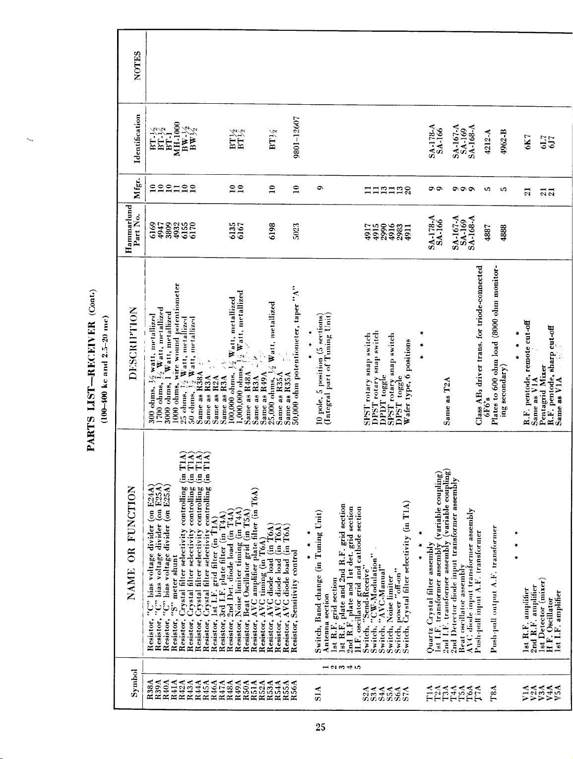
a
F
z
ez
iH
N,N
? îo
É\i\
e
r\É\E
| |
FFF*ÈF
fó6H:î
---HÈ-
q\q.N4Q
€SF9ql lJ1È-
-q€q--
\o.+
co
ri
À
<i
r*
\O \o
\N\"
FF
u:r
(n€
\o \O
\N
co
6
\o
r
f'o
Òì
m
òi
tó
llrl1o\Omd CO€
__E\-te-r
g\$O\O.O\6
++ói+ói+
f-f
co€
F-\o€
r- \O-\O
TììiÌ=F
<ui
<úi< ì *..
AAC)
f'o
f-f
F-\OOO
r.:
€lO
<(,) <ui<
aaa
16
ì -
Òt
N
r ó
cO cO
rrr
Y r.l-
.c)
\ó
\O
U
.r2
>x
r'èl
3ìT
rit€
lc,
J
,'
aé
?.
t''1
I
I
ib:
IE=Tf
'_2='i
z
:
l- =::-=
=
-
Z'ij;:::..-_-*-jì-\->
'ì,.;7Èlj-l
Q
i
i
ij€€€Z=eanF;=ftÉfr:ftn:-
ic:.:i==o
l=ÈF=::-a]ii+EFr==.-=c.
i
:
Tii!::
i=.i-az
-.z
.^-"'-
i
:7
,aaéf
g
s É1
=
.rpÈE.;:;p;
rÈ
ÈE .! t
;:
-;
:=
;É
.' -.d
jÍsÍ],Éf I
f
=
f
rr1-.q
2y2=29=
€ F
=
: !
-
j
i
n
jxg:
s
-t
=^
i
;
E:;=xì8dódd=:dddKdd8
Ez
.'?-
i* i,a i, -
..::
'!:
::
i;
;:. l.! È|íÉi
;T
?P
i:
=5
z
F
U
z
p
*
:; ! E
+= +'E
:; !
L-
-
L
|+:
r
:.i;::ì
a:-'^r--h
{.!=7!.È
à==aE> ó
:t
3F
tÈ
a:
'ioH
; F .i
€sì
g
g
E
:
*:
*
bEî
È
ÈÈ *:Érs
I
o
ú
^: :9 i>oÈ>
?"":É IE'8"!É
r€€r
q
3'
E *-
g
b€
i:9js
O E d"3dsi8
Z
€OCrNcîÉtÒ€rcOO\OÉNó+ú\O
mm\i+!i=i!iss++SUîu:nuît'orDú
a
È6t.O<iú)
1
ì
25
Nó!+ró\Or
aaaaaa
iNósr/ì€C-
FFFFFFS
CO
F.
Èòtft:grn
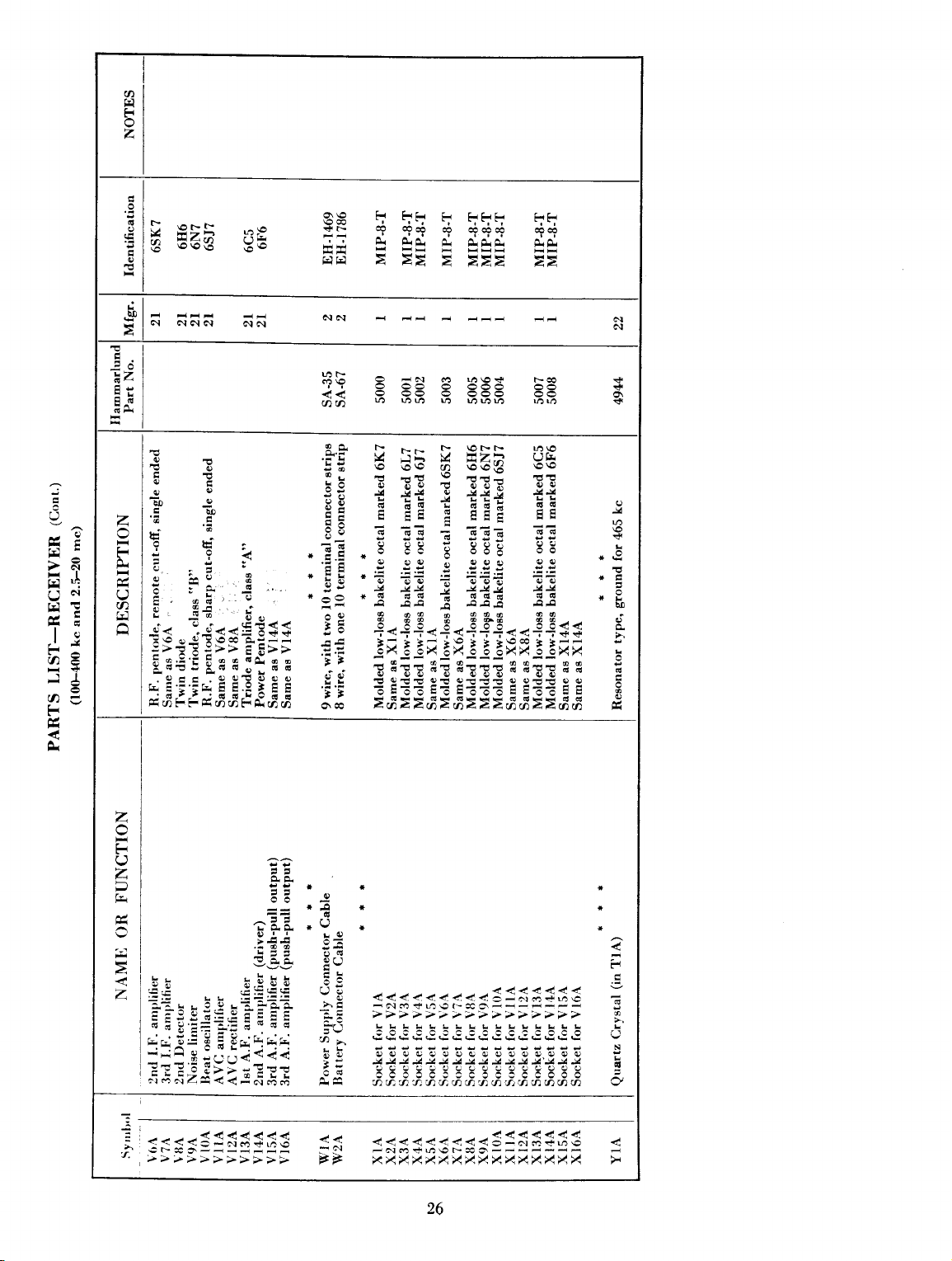
a
F
z
,î
U
*2
eì
r-
u-.
r-t
eì
rt
lt
1,,
J
,'
aé
Jé
9é
F
O
EAà
E
èD
ò.t 6t
E
6.t Òl
àz
ih
6E
9O
-co
z
E
F
:Y
e
''l
r
(î)
_i<
:>= ::>> É ts>>
:.o.:il.oú60.úD
:
3
cèo
.'6
Iq:
!.a
h:
c:-,j:
i ;;:
ju
;
".
6=
t X
d<<s€ss
!rO€
.!
r!
xro o_9
J::ijssÈiie
É,friiiódÈa:#,;
€€
6l Gl
E
b"
C.!:-
., 6 6
*r
C^l òl
Íi ?, 2 ,a,
?qqqqqq
À. A A
-H
H ÈBH
-É
EEp=estrr?ex
t/)
6ò
i.
I
g5
ib
3 r.
E!
i8
i= -5
.:'=
Ei
::
=c
E:
Éf
:.:
i i
ì
Ì
O\cO'2Aè2..nèAàèè.A,î2àAtA
u1u1 r,î
r
NÈ
5Èbú
T
TE ; €€:
r
.irr
E
EE
G
ci
!E
0
0 i o
ó)
*È
;+ È È,=;
j
j-É
*
jl
-3Í
+.++.g"+Éj..++ss
jx33;Ì;j::xijjix
*ri
r
È:ÈÈ
-:: i:;:li;
:
uìultrà
\Ol'-h-
F-
EaA
".
tÍ,4
EEE
!
?G;
;
EE!
È
o
!
t4t
,
i.oo
=
*i rrrr
:È:ÈÈÈ : :ÈÈ : !
* *3! * *
i:i E E
11r:
-f'Y
22
rco
rn ró
rrî\O
sÉ
TT
tÈ
Eg
E?
!E
o ú
:+
11
-o-o
N
<'
J
ú)
ù
è!
z
F
(,
z
P
??
==
î3. I
o.:-l
f€fgEe
:7 ?
eee
h! rb:: Eb
Z
È,+
a-:!
;l;È*1Él;i=
-. .:
:.rE=E=E1itl:-
--'i q
!! É=ÈÈ
L:=ia
r:_:
='i
=E .,-'.',.
-....)<14
-.==\,(-\_
- -
iEit,gì?!=;;
t
tt
*€
-Q
*
*
Lo
!r-.!
EO
ÙE
ì\=
E.- :::1::::::.':::- i
.tC .:.5.-h.5.:.:.:.:".:.b.à.:.3.5.8.È ó
h>
i
t-
rI
-^--rî€r-ca'=-----:
ù O O O C ! s s
c
-&JJJ-!,J-íJJ-1,J3-{J-!J
q g
! o s o o o
;s;i.s;.;si;;.sisaa &
26
*
+
3
i
J
:
=

a
Éi
z
r
r
U
U)
ró
N
t-a rlì
N;
ú-
6l
8ÈÈ
Ò,1
I
=..€oLî-
835=53
ú6NúNr4
À
\or
83
_'.-r
-\,)
o o-Í
j j-P
Z ZîtA
N
-
Z
ó
<
rr
UU
aa
rn
crì
ró
c.l
^
:i
az
6H
n
i6\OO\rJîi
\O\Ol..irN
rnLÒòth6tù1
ca
aÒ61
6
<
\o
ct
o\ir
<6ró
h1.l
:ì
ts-
a
z
:4
i=
l^
;-
U
I
3
a
a
rl
a
F
G-
Òì
==
r4cn-
d'
-?.
as
>u
'ú
No
-v
,.&
"
àbbb
*
ii
il
ì
J3
z
F
rl
z
,h.ì
À
z
hfr N
À2
Es
E
&
F
+
a
a
a
!
U
= =
5
i
à= ";È
ta
b'!
d!
gi'
a:i
=J=
.=r-
* *>; *
ilît
=-
* *+a *
" -i3 *
:j
i'=
lrs
U
òl
a
ó
Fd
UU Ii
=iÍ
ÉÉÉ
Nms
r.l r.ì r.l
rî
o
.E
=.i
-i
-3;=?
z.i.
?.
É
È? ll
e ÙÙ
=
TT
i: ++
;
:i ní
i 22
ÉCq
cq
-N
.-
-
f
,1
";I
*r9ió
.il}
.-È
=:L
.
hf; *
=i'ii
*E:ri: *
)rsj
j"à=Èà*,-
j==
=
!;
-:
-=
,:i.
€ca
-N
5
l!j=
à
A:.:,
tà'*iJ
'
:;'- i
\rr;
:==-
aií:a
;,;.;;,
:.
É
6-.1
z
!
i
-
|
i
:
r': T :-
L
L
>r>
++
'ió
-iiàó
a
t
'=
r
=
^
-aì
>.>
Èù
66
-!,e
XX
-N
XX
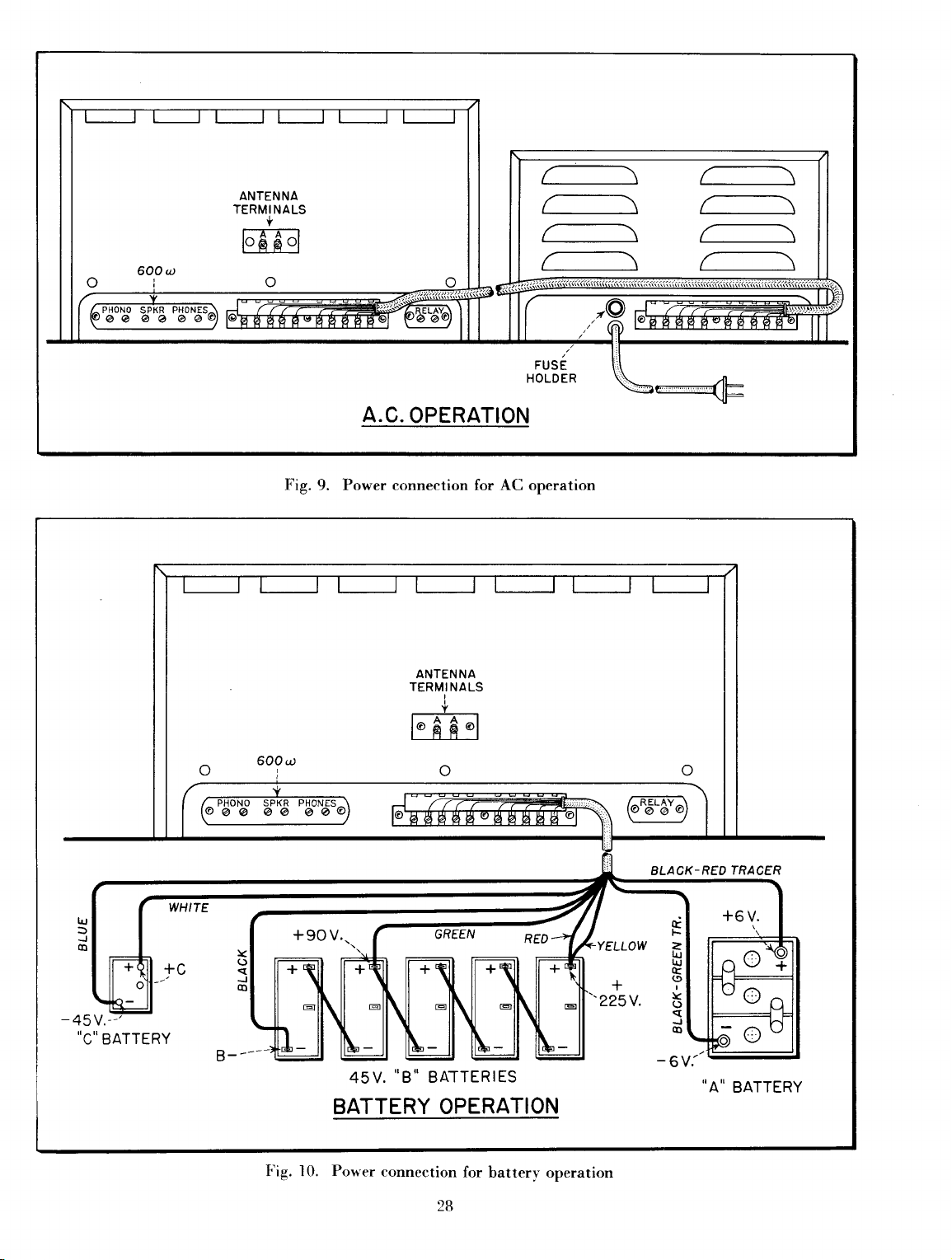
A.C.
OPERATION
..C..BATTERY
Fig.
Power connection
9.
AC operation
for
-L
'225V.
BLACK-REO
t
F
=
rU
r{J
c
(t
I
Y
o
J
o
TRACER
F ig.
.'8..
45V.
BATTERIES
BATTERY OPERATION
-l
Porter
0.
connection
28
for
batterv operation
"A"
BATTERY
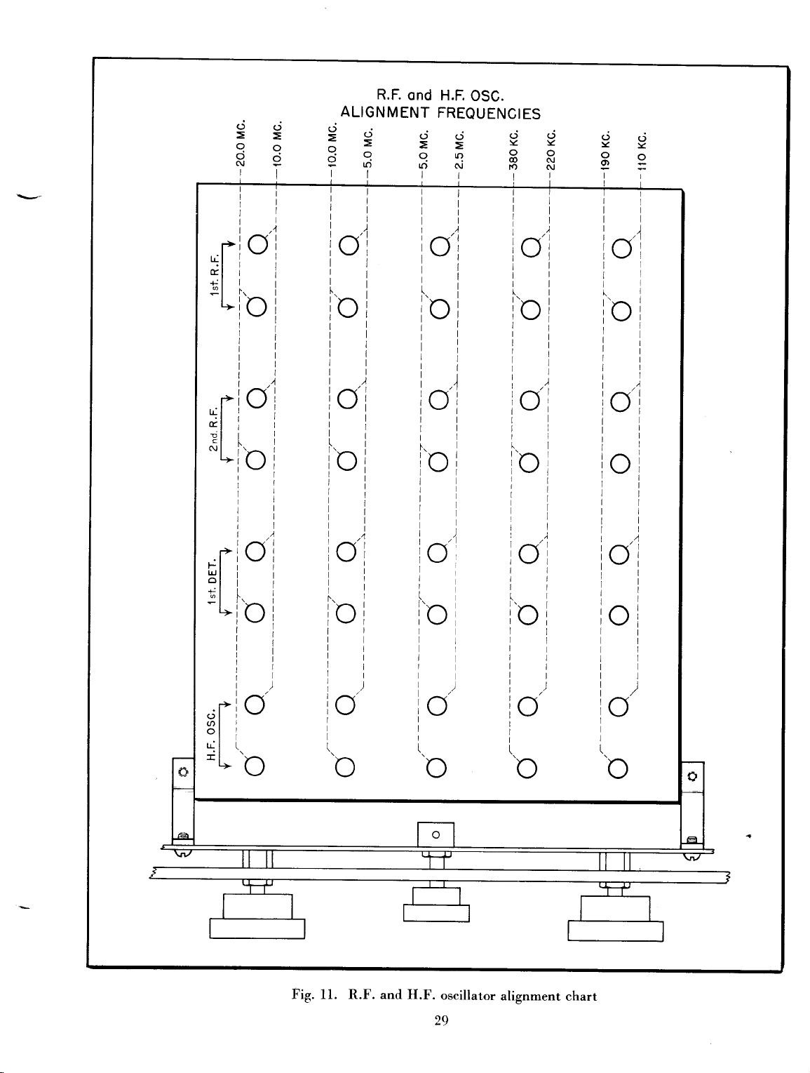
il
ji
ll
t,4
ici
.'r
Èl
lt
:t
+l
I
al
+
It I
I
I
I
I
I
I
I
f
r'i
tll
I
El I
!t
I
<l
I
'l
i
+f
c
I
r>
C,,I
..1
Il
îl
+r
ol
r>
o
R.F.
ond H.F.
ALIGNMENT
()-j
==33
Xooú)
Yr;dÀi
rtlt
illtir
lllr!l
Itlill
i"l i.i ,o!,
rrill
ri
lliti
llirl
|
i..^
lCi
i'
roi
OSC.
FREQUENCIES
lvi
1l
il
|
1..
i'o
I
I
I
I
)
/l
I
I
l
i"i
iiii
iiii
riil
,4
I
i)i)i
(a"',
i
;vi
i-ii-t
i^ii,^j
ici
iill
i;ii
titi
ll
ril
t)))i
|
-. i
(1''
i
V,
i
itii
iii
l.i(l
i'n I r'rì
;\-/
lltl
llrr
llrl
lrrtl
ltrl
',.
^"'r
lvj
ici
i6
\J
,v I
i
1-,
\-/
,'c
(a'
\-/
,
ói
I
À
.ir
3l
.l
rl
;l
L>
o'
c
ioj
rr.-z
ll
Irl
(t(
\J
Fig. f l. R.F. and H.F.
c)
!v
rl
\-/
oscillator
29
lV
\-/
alignment
o
chart
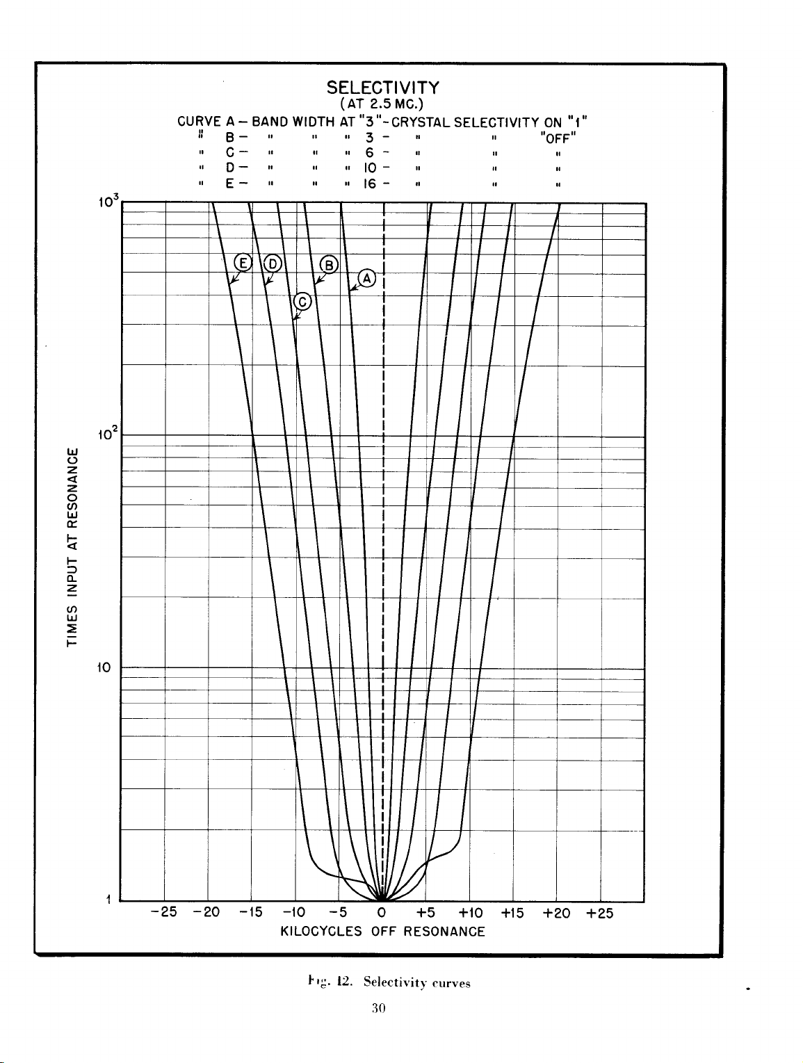
103
ll
,r
r
,r
A_
B-
CDE-
GURVE
v
BAND
l\
(e
SELECTIVITY
(AT
2.s Mc.)
WIDTH AT,'3,.-CRYSTALSELEGTIVITY
,
r
tr
r tr
\fo)l
Y
I
n ,r
l
r
tl
tl
1I I
(s
v
-
r
,t
u
3
$
lO
16-
-
-
tr
l
r
.r
II
r,
r
l
rr
I
I I
I I I I
-I
tru
-T
ON
"OFF"
x
Í
r
''I''
UJ
o
z
z
o
a
lrl
É,
<t
F
f
fL
z
a
lrJ
=
F
l02
to
P\
I
\ I
I
I
I
I
T
-25 -20
!
-15 -tO
KILOCYCLES
lrg.
-5
12.
I
U
0 +5 +10
OFF RESONANCE
Selectivitv
30
curves
+15
+20 +25
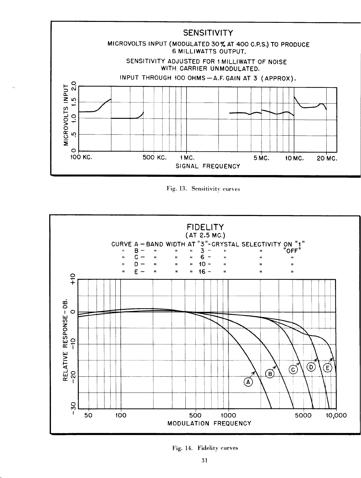
r-Q
fN
o-
=2
a
L
:q
t-
o
5q
o
roo
Kc.
MlcRovoLTS
SENSITIVITY
rNPUT
THROUGH tOO
500
tNpuT
WITH
Kc. I
SENSITIVITY
(MODULATEO3O/"
6
MILLIWATTS
ADJUSTED
FOR 1
CARRIER UNMODULATED.
OHMS-A.F.GAtN
MC.
SIGNAL
Fig.
13.
FREOUENCY
Sensitivitv
AT 4OO
OUTPUT.
MILLIWATT
curves
C.p.S.) TO PRODUCE
OF NOISE
(AppROX).
AT
3
s
Mc. ro Mc.
\ ,-a\
20 Mc.
9
+
frl
o
to
lrJ
a
z
o
fL
úo
ET
lrJ
z
F
=o
ll-
|
o
ro
I
50
,'
,,
r
,,
A
BGD-
E-
CURVE
roo
-
BAND WIDTH AT
r rr ,,
r
rr u ,,
rr
r ,,
r ,r
MODULATION FREOUENCY
FIDELITY
(
Ar
2.s Mc.)
.'3''-CRYSTAL
-
3
6
lO-
16-
500
r.
-
rr rr rl
r r rl
l n x
1000
SELECTIVITY
r,
ON
ttOFFt'
B
A
\
,'I.'
ó\(P\G
\
Ir \
5OOO
|O,OOo
Fig. 14. Fidelitv
3l
curves

,l
1
r*
t"'
N
co
r{
ú-
{;
'Vl
ì
fL
0.
f,
U'
G
ul
ì
!
èD
o
o-
I
ào
Ì
>.
l!
-llt'*
rò
\d/
É
o
s
o
L
f
u
É
u
a
k
,
rn
èo
32
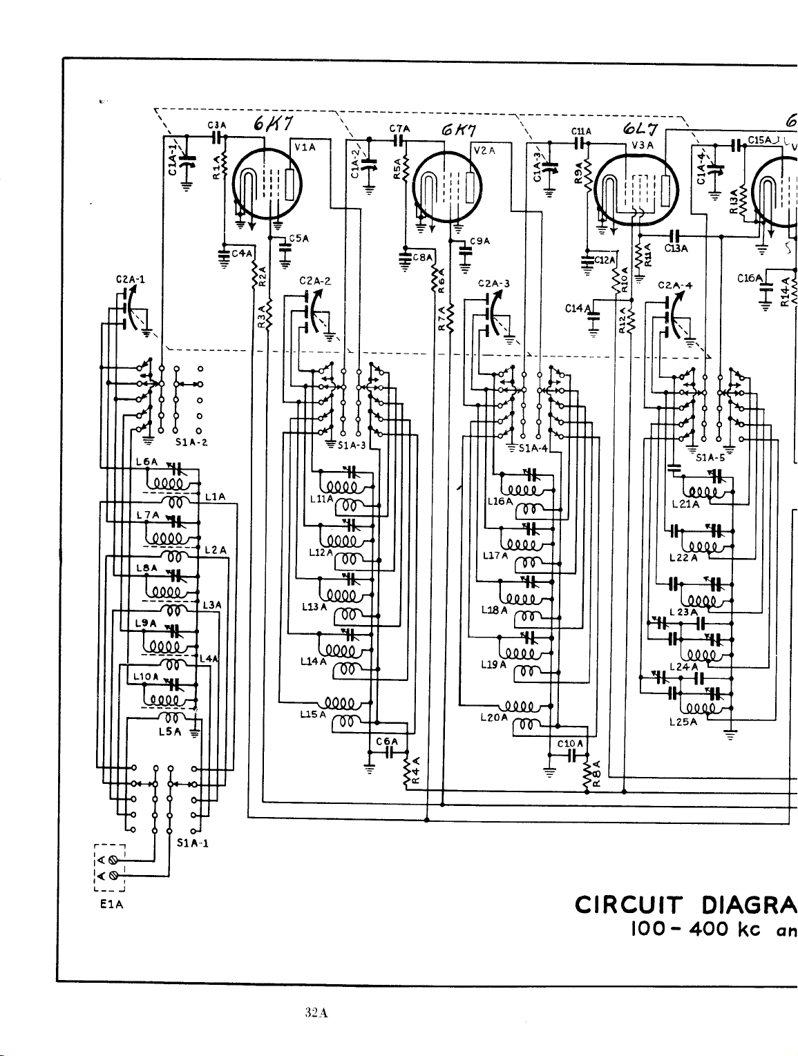
\l
rl
îl
^i-
àa
()l
J-
=
c,3^
Í
J-
+
ú
T
l<q
L--
E1A
J
CIRCUIT
loo
DIAGRA
-
4OO
kc
on

6
'v+A
------r---L26A
T1A
r=-----r{3t*!?Ia
--Í------------r
-
- --'T:--'
1A
Gl
t
É.
;
o
t
6t7
ti
<l
r\!
I
arl
I
+l
I
=
a
ú.
6 sK7
o|
(J
o
t
aÉ.
t
6h
ú
I
I
I
I
J
63/{7
r4Aili
---J
I(
F)
?9
!t
+rl
o
lL-
c+1A
t32A
9lfAi
r-
!o
IJ
t<i
l@
tO
l()
I
o
N
<F
úT
O-I
=
AM
-
rnd 2.5
RECEIVER
-
20
mc
M1A
I1A
I?A I3A
RELAY
E2A.
c2+A
Gc5
v13A
PfroNo

65tr7
N
o
6H6
ó
€,rF
6€lf7
I
I
l<
:d
rh
i
I
i<
rm
L
+
o
r)
n
3+A
N
O
o
IA
)
I
\
RELAY
6
N
É.
PHONO S PKR
óFé
PHONES
J1A
N
d
109876s+32L

LIST OF
MANUFACTURERS
No.
American
I
Beìden
2
Beede
J
Bussmann
4
D
Chicago
Cornell-Dubilier
6
Littìefuse
7
Ce'rcral
B
Ilamrnarlund
9
l0
International
l1
Clarostat
I lou ard
t2
13
Crrtler-HamIner,
Kurz-Kasch
14
Acrovox Corp..
l5
P.
ìó
17
]B
19
20
21
22
z)
ot
ZJ
26
R.
\f,-eston Fllectrical
Utalì Radio
National Lock Co.
(
)aL \l
R.C.A.
R.C.A.
F. \\-. Sickles
\\'irt
Par-\Ietal
American
N,c.MB
Phenolic Corp.
N{fg. Co.
Fllectrical Instrument Co.
1\{fg. Co.
Transformet Corp.
Iilectric Corp.
Inc.
IÌlectric Co.
NIfg.
Resistance Co.
\lfg.
Co.
ones
Iì.
J
Inc.
Co.,
.
Co.
Inc..
.
Co.
\Iallorv & Co., Inc.
.
Instrument Co.
Products Co.
.
fg. Co.
Co.
.
.
NIfg. Co.
\Ifg.
Co.
Companv
Products
Corp.
limbìem ComJranr
Aoonpss
Chicago,
Chicago,
Ill.
Ill.
Penacook, N. H.
New York, N. Y.
Chicago,
South
Chicago,
Cleveland,
New
Ill.
Plainfield, N.
Ill.
Ohio
N. Y.
York,
Philadelphia, Pa.
Ill.
N.
Y.
Brooklyn,
Chicago,
Milwaukee, Wisc.
Dayton,
Ohio
lrlew Bedford, Mass.
Indianapolis, Ind.
Nervark,
Chicago,
Rockfortl,
Chicago.
Harrison,
Camden,
Springfield,
PhiladelPhia,
Long Island
Utica,
N.
Ill.
Illinois
N.
N.
N.
Y'
J.
Ill.
J.
J.
Mass.
Penna.
Citv,
N'
J.
Y.
33

F
H
t
CAUT'ION
when
ifs
dusf
cover
tap
rvhich
with
a line
volt
+ap.
An
ex'ira
tnollinE
operaiion
dusf
leokl:rg
!ong
sllgh'í'ly
*eeth
the
while
t[:e
{:over
d**'n
se.e,v
ra;ki;rg
to
engege.
banri
holding
fhe
Powen
of$
will
afferd
vol*age
heavy
r,raln
o'i'the
srvi*eh
cjial
removecj
bef",ree;r
d,'i,rer
ii:e
ciiaN,
fhe
sup;:ry
to
éyo;ei
safisrrac;ory
of
r
shcci.
dial
r,rask
rnesk,
{ron'l
the
eareiruiiy
ba*cj
s.,:.jsh
lf *he
ciiai
i*
can
ieiler
geq;.
unit
rnusf
sverheating.
cperafion
| 7,
use
*he
ciuring
to
vrhen
the
s-rneter
nrask
lunrp
fhe
receiver,
s;:ring
kn,:b
ihen
be
turned
out
of
rniprnen*
or-r.l
banei
enc
this
rnesh.
be
[,rse
| ?5
,;{
rnesh.
switch
this
ihe
idier
beck
does
by
operated
ihe
highesi
of the
volt
tap
mùy
cèuse
This
knob
idler
main
dial
gear
and
forth
nct
properly
hand
io
continuousry
primary
receiver.
rather
may
is
gear
escutcheon.
back
to
the
For
than
the
idler
result
turned.
can
be
into
permit
synchronize
correc+
reave
vortage
example:
the
r 15
gear
con-
in
faulty
with
the
seen
wifh
line
while
the
gear
with
position
by
a
'Íront
The
es;q.rtcheon
*hem
ín
on fhe
band
srvi*eh
disfiieui*
assembly
iom
are
f'!cti*n
p.ri:'*f
fr.tm;\elto'.r*:en
wifi':
repí*cncl
fo
To
eorreci
cover
tighfly
drive
pliei':.
the c-li*!
exeti;y
panei
fo
press
díal
kneb,
fu;'n.
This
l;eel
a
íeuÍt'ir
píelli:
squee:ing
sirair'b-v
lf
;r heeor'.;:iro,:k
Ìiie
ìr"r
if*
may
heervlli,
rnesk.
any
ex-ire
condi'ilon
suffir;ien*
*perafion
i:"c;"rr
*ire
*he
e.Jge
a hex
ill:ci,',he
;:r*pe;'
*s ii:,;v
v,,crc.
be
hent
cluring
eno,rgh
since
''he,
frlcilon
can
be
.rrnculi.l
ot
i"c,seive:
nu'i
ou*er
rcsifien.
and
of
lhe
r.iirich
iras
caused
dísc
*riEinally
shiprnent
again:t
mask
is
*n
the
mask
relieved
io
pernr;t
.fricilon
a
moJ;e
c{ial.
can
be
the
niust
Make
assembied.
fhe
main
driven
wiil
by
springing
the
mask
dial
drive
sui"e
ihe
These
sure
discs
fightened
dialto
be
removed
the
causiirg
dial
guides
fhrough
make
the
the
to
rotate
remove
fwo
friction
are
with
completely
iump
and
several
fhe
main
to pinch
gears
by
band
switch
dial
guide
{ree!y.
the
bot-
discs
held
on
a wrench
replaced
washers
dial
the
the
or
out
are
 Loading...